EP4239705A1 - Coating die for lithium secondary battery, including removable spacer shims - Google Patents
Coating die for lithium secondary battery, including removable spacer shims Download PDFInfo
- Publication number
- EP4239705A1 EP4239705A1 EP22881332.5A EP22881332A EP4239705A1 EP 4239705 A1 EP4239705 A1 EP 4239705A1 EP 22881332 A EP22881332 A EP 22881332A EP 4239705 A1 EP4239705 A1 EP 4239705A1
- Authority
- EP
- European Patent Office
- Prior art keywords
- die plate
- coating
- upper die
- spacer shims
- coating die
- Prior art date
- Legal status (The legal status is an assumption and is not a legal conclusion. Google has not performed a legal analysis and makes no representation as to the accuracy of the status listed.)
- Granted
Links
Images

Classifications
-
- B—PERFORMING OPERATIONS; TRANSPORTING
- B05—SPRAYING OR ATOMISING IN GENERAL; APPLYING FLUENT MATERIALS TO SURFACES, IN GENERAL
- B05C—APPARATUS FOR APPLYING FLUENT MATERIALS TO SURFACES, IN GENERAL
- B05C5/00—Apparatus in which liquid or other fluent material is projected, poured or allowed to flow on to the surface of the work
- B05C5/02—Apparatus in which liquid or other fluent material is projected, poured or allowed to flow on to the surface of the work the liquid or other fluent material being discharged through an outlet orifice by pressure, e.g. from an outlet device in contact or almost in contact, with the work
- B05C5/0254—Coating heads with slot-shaped outlet
-
- H—ELECTRICITY
- H01—ELECTRIC ELEMENTS
- H01M—PROCESSES OR MEANS, e.g. BATTERIES, FOR THE DIRECT CONVERSION OF CHEMICAL ENERGY INTO ELECTRICAL ENERGY
- H01M10/00—Secondary cells; Manufacture thereof
- H01M10/05—Accumulators with non-aqueous electrolyte
- H01M10/052—Li-accumulators
-
- B—PERFORMING OPERATIONS; TRANSPORTING
- B05—SPRAYING OR ATOMISING IN GENERAL; APPLYING FLUENT MATERIALS TO SURFACES, IN GENERAL
- B05C—APPARATUS FOR APPLYING FLUENT MATERIALS TO SURFACES, IN GENERAL
- B05C5/00—Apparatus in which liquid or other fluent material is projected, poured or allowed to flow on to the surface of the work
- B05C5/02—Apparatus in which liquid or other fluent material is projected, poured or allowed to flow on to the surface of the work the liquid or other fluent material being discharged through an outlet orifice by pressure, e.g. from an outlet device in contact or almost in contact, with the work
- B05C5/0254—Coating heads with slot-shaped outlet
- B05C5/0262—Coating heads with slot-shaped outlet adjustable in width, i.e. having lips movable relative to each other in order to modify the slot width, e.g. to close it
-
- B—PERFORMING OPERATIONS; TRANSPORTING
- B05—SPRAYING OR ATOMISING IN GENERAL; APPLYING FLUENT MATERIALS TO SURFACES, IN GENERAL
- B05C—APPARATUS FOR APPLYING FLUENT MATERIALS TO SURFACES, IN GENERAL
- B05C9/00—Apparatus or plant for applying liquid or other fluent material to surfaces by means not covered by any preceding group, or in which the means of applying the liquid or other fluent material is not important
- B05C9/06—Apparatus or plant for applying liquid or other fluent material to surfaces by means not covered by any preceding group, or in which the means of applying the liquid or other fluent material is not important for applying two different liquids or other fluent materials, or the same liquid or other fluent material twice, to the same side of the work
-
- H—ELECTRICITY
- H01—ELECTRIC ELEMENTS
- H01M—PROCESSES OR MEANS, e.g. BATTERIES, FOR THE DIRECT CONVERSION OF CHEMICAL ENERGY INTO ELECTRICAL ENERGY
- H01M4/00—Electrodes
- H01M4/02—Electrodes composed of, or comprising, active material
- H01M4/13—Electrodes for accumulators with non-aqueous electrolyte, e.g. for lithium-accumulators; Processes of manufacture thereof
- H01M4/139—Processes of manufacture
-
- B—PERFORMING OPERATIONS; TRANSPORTING
- B05—SPRAYING OR ATOMISING IN GENERAL; APPLYING FLUENT MATERIALS TO SURFACES, IN GENERAL
- B05C—APPARATUS FOR APPLYING FLUENT MATERIALS TO SURFACES, IN GENERAL
- B05C5/00—Apparatus in which liquid or other fluent material is projected, poured or allowed to flow on to the surface of the work
- B05C5/02—Apparatus in which liquid or other fluent material is projected, poured or allowed to flow on to the surface of the work the liquid or other fluent material being discharged through an outlet orifice by pressure, e.g. from an outlet device in contact or almost in contact, with the work
- B05C5/027—Coating heads with several outlets, e.g. aligned transversally to the moving direction of a web to be coated
-
- H—ELECTRICITY
- H01—ELECTRIC ELEMENTS
- H01M—PROCESSES OR MEANS, e.g. BATTERIES, FOR THE DIRECT CONVERSION OF CHEMICAL ENERGY INTO ELECTRICAL ENERGY
- H01M10/00—Secondary cells; Manufacture thereof
- H01M10/42—Methods or arrangements for servicing or maintenance of secondary cells or secondary half-cells
- H01M10/4235—Safety or regulating additives or arrangements in electrodes, separators or electrolyte
-
- H—ELECTRICITY
- H01—ELECTRIC ELEMENTS
- H01M—PROCESSES OR MEANS, e.g. BATTERIES, FOR THE DIRECT CONVERSION OF CHEMICAL ENERGY INTO ELECTRICAL ENERGY
- H01M4/00—Electrodes
- H01M4/02—Electrodes composed of, or comprising, active material
- H01M4/04—Processes of manufacture in general
- H01M4/0402—Methods of deposition of the material
- H01M4/0404—Methods of deposition of the material by coating on electrode collectors
-
- Y—GENERAL TAGGING OF NEW TECHNOLOGICAL DEVELOPMENTS; GENERAL TAGGING OF CROSS-SECTIONAL TECHNOLOGIES SPANNING OVER SEVERAL SECTIONS OF THE IPC; TECHNICAL SUBJECTS COVERED BY FORMER USPC CROSS-REFERENCE ART COLLECTIONS [XRACs] AND DIGESTS
- Y02—TECHNOLOGIES OR APPLICATIONS FOR MITIGATION OR ADAPTATION AGAINST CLIMATE CHANGE
- Y02E—REDUCTION OF GREENHOUSE GAS [GHG] EMISSIONS, RELATED TO ENERGY GENERATION, TRANSMISSION OR DISTRIBUTION
- Y02E60/00—Enabling technologies; Technologies with a potential or indirect contribution to GHG emissions mitigation
- Y02E60/10—Energy storage using batteries
Definitions
- the present disclosure relates to a coating die for lithium secondary battery including removable spacer shims
- lithium secondary battery exhibiting a high energy density and operating voltage, a long cycle lifespan, and a low self-discharge rate, which is now commercialized and widely used.
- EV electric vehicle
- HEV hybrid electric vehicle
- a lithium secondary battery having high energy density, discharge voltage and output stability is mainly studied and used as a power source for the electric vehicle (EV), the hybrid electric vehicle (HEV) and the like.
- Such a lithium secondary battery is generally manufactured by stacking or winding electrodes of cathode and anode with a separator interposed therebetween, and incorporating them together with an electrolyte solution in a battery case.
- electrodes such as the cathode and the anode are manufactured by applying, drying, and rolling an active material slurry on a current collector, wherein the application of the active material slurry is generally performed by a coating die that discharges the active material slurry.
- a perspective view of the coating die is shown as an example in Fig. 1 below.
- such a coating die is composed of an upper coating die 11, a lower coating die 12, and a shim assembly 13 interposed therebetween, wherein the shim assembly 13 has a structure in which a body shim 14 for forming a connection between the upper coating die 11 and the lower coating die 12, and spacer shims 15, 16, 17 and 18 for discharging an insulating liquid are integrated.
- the integrated shim assembly shows many difficulties in the adjustment of individual slurry width, loading, and mismatch, and has problems with precision design and assembly of the spacer shims in simultaneously forming the insulating liquid and the active material slurry.
- a coating die for a lithium secondary battery there is provided a coating die for a lithium secondary battery
- the upper die plate may include an insulating liquid injection path into which an insulating liquid is injected.
- the insulating liquid injection path may be formed from an upper part to a lower part.
- the lower die plate is coupled to the upper die plate, and may include a slurry injection path into which the active material slurry is injected, and a manifold that stores the active material slurry, wherein the lower die plate is coupled to the upper die plate by a fixing pin, a fixing bolt, or both.
- the body shim is coupled with the upper die plate and the lower die plate, and may have an outlet port that is opened from the manifold toward the outside where the coating is performed and thus discharges the active material slurry stored in the manifold, so as not to cover the manifold formed on the lower die plate and storing the active material slurry.
- the body shim may be coupled to the upper die plate and the lower die plate by a fixing pin, a fixing bolt, or both.
- the spacer shims are individually coupled with the upper die plate, the lower die plate, or the upper die plate and the lower die plate, and may include an insulated flow passage that positioned so as to correspond to an insulating liquid injection path of the upper die plate, stores and discharges the insulating liquid injected from the injection path of the upper die plate.
- the spacer shims may be coupled with the upper die plate, the lower die plate, or the upper and lower die plates by a fixing pin, a fixing bolt, or both.
- the fixing pin and the fixing bolt are formed by a structure capable of coupling and removal, and thus, can be formed so that the spacer shims are removable from the coating die.
- the spacer shims may consist of one or more numbers or may be included less than or equal to the number of insulating liquid injection paths formed on the upper die plate.
- a coating die for a lithium secondary battery there is provided a coating die for a lithium secondary battery
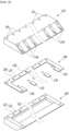
- Fig. 2 is a perspective view of a coating die for a lithium secondary battery according to one embodiment of the present disclosure
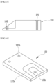
- Fig. 3 is a cross-sectional view of the upper die plate 110 of the coating die
- Fig. 4 is a perspective view of one spacer shim 132 of the coating die.
- the coating die for a lithium secondary battery includes an upper die plate 110, a lower die plate 120, and a shim assembly 130 interposed between the upper die plate 110 and the lower die plate 120, wherein the shim assembly 130 includes a body shim 131 and one or more spacer shims 132, 133, 134 and 135.
- the upper die plate 110 includes coupling holes 141 into which fixing pins, fixing bolts, or both for coupling with the lower die plate 120 are inserted, and insulating liquid injection paths 142 into which an insulating liquid is injected.
- the insulating liquid injection path 142 is formed from the upper part to the lower part and is formed so as to pass through the upper die plate 110, which makes it possible to inject the insulating liquid into the spacer shims 132, 133, 134 and 135 through the insulating liquid injection paths 142.
- the coupling hole 141 is formed for coupling between the body shim 130 and the lower die plate 120, which will be described later.
- the lower die plate 120 includes a slurry injection path into which the active material slurry is injected (not shown in the figure), and a manifold 121 that stores the active material slurry.
- the slurry injection path has a structure that is connected to the manifold 121. Therefore, the active material slurry injected from the slurry injection path reaches the manifold 121 and is stored.
- the active material slurry stored in the manifold 121 performs electrode coating in the form of being discharged from the outlet port 136 of the body shim 131 of the shim assembly 130 of the coating die in an assembled state, which will be described later.
- the lower die plate 120 is coupled to the upper die plate 110, wherein since it can be coupled by a fixing pin, a fixing bolt, or both, and the lower die plate 120 can also include coupling holes 122 and 123 that can be coupled with the upper die plate 110.
- the body shim 131 has an outlet port 136 that is opened from the manifold 121 toward the outside where the coating is performed and thus discharges the active material slurry stored in the manifold 121, so as not to cover the manifold 121 formed on the lower die plate 120 and storing the active material slurry.
- the active material slurry stored in the manifold 121 is discharged through the outlet port 136.
- the body shim 131 simply has a' ' ⁇ ' shape.
- the body shim 131 is coupled with the upper die plate 110 and the lower die plate 120.
- the coupling of the body shim 131 may also be formed by a fixing pin, a fixing bolt, or both, and thus, the body shim 131 may include coupling holes 137 and 138 into which they can be inserted.
- the spacer shims 132 , 133 , 134 and 135 included in the coating die 100 of the present disclosure are configured to be individually removable.
- the spacer shims 132 , 133 , 134 and 135 are individually coupled with the upper die plate 110, the lower die plate 120, or the upper die plate 110 and the lower die plate 120.
- the spacer shims 132, 133, 134 and 135 can be coupled to the upper die plate 110, the lower die plate 120, or the upper die plate 110 and the lower plate 120 by a fixing pin, a fixing bolt, or both.
- the fixing pin and the fixing bolt are formed by a structure capable of coupling and removal, so that the spacer shims 132, 133, 134 and 135 are formed to be removable from the coating die 100.
- the spacer shims 132, 133, 134 and 135 may be formed at any position corresponding to the insulating liquid injection path 142 of the die upper plate 110, and the width and formation position thereof can be appropriately selected as needed.
- the spacer shims may consist of one or more numbers or may be included less than or equal to the number of insulation liquid injection paths formed on the upper plate of the die. Specifically, it is preferable that the number of spacer shims is 1 or more, specifically 2 or more, and more specifically 3 or more.
- the spacer shims 132, 133, 134 and 135 is individually removable from the coating die 100, and the number and position of each can be changed, thus enabling adjustment of the coating width, loading, and mismatch between active material slurry and insulating liquid.
- Fig. 4 schematically shows a perspective view of one of these spacer shims 132.
- the spacer shim 132 includes coupling holes 132b and 132c for coupling with the upper die plate 110 and/or the lower die plate 120.
- the spacer shims 132, 133, 134 and 135 specifically serve to coat the insulating liquid. Therefore, the spacer shims 132, 133, 134 and 135 include an insulating flow passage 132a through which the insulating liquid injected from the insulating liquid input path 142 of the die upper plate 110 is discharged to the outside of the coating die 100.
- the active material slurry of the manifold 121 of the lower die plate 120 is discharged and coated by the outlet port 136 of the body shim 131, and the insulating liquid is discharged and coated through the insulating flow passages 132a of the spacer shims 132, 133, 134 and 135.
- a coating die for a lithium secondary battery according to the present disclosure has a removable spacer shim that discharges the insulating liquid, and has an effect of enabling adjustment of the coating width, loading, and mismatch of the active material slurry and the insulating liquid, if necessary.
Landscapes
- Engineering & Computer Science (AREA)
- Chemical & Material Sciences (AREA)
- Manufacturing & Machinery (AREA)
- Chemical Kinetics & Catalysis (AREA)
- Electrochemistry (AREA)
- General Chemical & Material Sciences (AREA)
- Materials Engineering (AREA)
- Battery Electrode And Active Subsutance (AREA)
- Coating Apparatus (AREA)
Abstract
Description
- This application claims the benefit of
Korean Patent Application No. 10-2021-0135173 filed on October 12, 2021 - The present disclosure relates to a coating die for lithium secondary battery including removable spacer shims
- With the technology development and increased demand for mobile devices, demand for secondary batteries as energy sources has been rapidly increasing. Among such secondary batteries is a lithium secondary battery exhibiting a high energy density and operating voltage, a long cycle lifespan, and a low self-discharge rate, which is now commercialized and widely used.
- Also, recently, as interest in environmental issues grows, studies are frequently conducted on an electric vehicle (EV), a hybrid electric vehicle (HEV), etc. which can replace a vehicle using fossil fuels such as a gasoline vehicle and a diesel vehicle, which are one of the main causes of air pollution. A lithium secondary battery having high energy density, discharge voltage and output stability is mainly studied and used as a power source for the electric vehicle (EV), the hybrid electric vehicle (HEV) and the like.
- Such a lithium secondary battery is generally manufactured by stacking or winding electrodes of cathode and anode with a separator interposed therebetween, and incorporating them together with an electrolyte solution in a battery case.
- Among them, electrodes such as the cathode and the anode are manufactured by applying, drying, and rolling an active material slurry on a current collector, wherein the application of the active material slurry is generally performed by a coating die that discharges the active material slurry.
- At this time, a perspective view of the coating die is shown as an example in
Fig. 1 below. - Referring to
Fig. 1 below, such a coating die is composed of anupper coating die 11, alower coating die 12, and ashim assembly 13 interposed therebetween, wherein theshim assembly 13 has a structure in which abody shim 14 for forming a connection between theupper coating die 11 and thelower coating die 12, andspacer shims - However, recently, as the number of lanes for manufacturing electrodes increases and the width of metal foil used as a current collector increases, the integrated shim assembly shows many difficulties in the adjustment of individual slurry width, loading, and mismatch, and has problems with precision design and assembly of the spacer shims in simultaneously forming the insulating liquid and the active material slurry.
- Therefore, there is a need to develop a technology that can solve the above problems.
- It is an object of the present disclosure to provide a coating die for a lithium secondary battery having a novel structure that allows adjustment of the coating width, loading, and mismatch of an active material slurry or an insulating liquid for each lane as needed.
- According to one embodiment of the present disclosure, there is provided a coating die for a lithium secondary battery,
- the coating die comprising an upper die plate, a lower die plate, and a shim assembly interposed between the upper die plate and the lower die plate,
- wherein the shim assembly includes a body shim and one or more spacer shims, and
- wherein the spacer shims are formed to be individually removable from the coating die.
- In one specific embodiment, the upper die plate may include an insulating liquid injection path into which an insulating liquid is injected.
- Wherein, the insulating liquid injection path may be formed from an upper part to a lower part.
- In one specific embodiment, the lower die plate is coupled to the upper die plate, and may include a slurry injection path into which the active material slurry is injected, and a manifold that stores the active material slurry, wherein the lower die plate is coupled to the upper die plate by a fixing pin, a fixing bolt, or both.
- In one specific embodiment, the body shim is coupled with the upper die plate and the lower die plate, and may have an outlet port that is opened from the manifold toward the outside where the coating is performed and thus discharges the active material slurry stored in the manifold, so as not to cover the manifold formed on the lower die plate and storing the active material slurry.
- Wherein, the body shim may be coupled to the upper die plate and the lower die plate by a fixing pin, a fixing bolt, or both.
- In one specific embodiment, the spacer shims are individually coupled with the upper die plate, the lower die plate, or the upper die plate and the lower die plate, and may include an insulated flow passage that positioned so as to correspond to an insulating liquid injection path of the upper die plate, stores and discharges the insulating liquid injected from the injection path of the upper die plate.
- Wherein, the spacer shims may be coupled with the upper die plate, the lower die plate, or the upper and lower die plates by a fixing pin, a fixing bolt, or both.
- Further, the fixing pin and the fixing bolt are formed by a structure capable of coupling and removal, and thus, can be formed so that the spacer shims are removable from the coating die.
- The spacer shims may consist of one or more numbers or may be included less than or equal to the number of insulating liquid injection paths formed on the upper die plate.
-
-
Fig. 1 is a perspective view of a conventional coating die for a lithium secondary battery; -
Fig. 2 is a perspective view of a coating die for a lithium secondary battery according to one embodiment of the present disclosure; -
Fig. 3 is a cross-sectional view of the upper die plate ofFig. 1 ; and -
Fig. 4 is a perspective view of the spacer shim ofFig. 1 . - Terms or words used in the present specification and claims should not be construed as limited to ordinary or dictionary terms, and the present disclosure should be construed with meanings and concepts that are consistent with the technical idea of the present disclosure based on the principle that the inventors may appropriately define concepts of the terms to appropriately describe their own disclosure in the best way. Accordingly, the embodiments described herein and the configurations shown in the drawings are only most preferable embodiments of the present disclosure and do not represent the entire spirit of the present disclosure, so it should be appreciated that there may be various equivalents and modifications that can replace the embodiments and the configurations at the time at which the present application is filed, and the scope of the present invention is not limited to the embodiments described below.
- Hereinafter, the present disclosure will be described in detail with reference to the accompanying drawings. Terms or words used in the present specification and claims should not be construed as limited to ordinary or dictionary terms, and the present disclosure should be construed with meanings and concepts that are consistent with the technical idea of the present disclosure based on the principle that the inventors may appropriately define concepts of the terms to appropriately describe their own disclosure in the best way.
- Further, the embodiments described herein and the configurations shown in the drawings are only most preferable embodiments of the present disclosure and do not represent the entire spirit of the present disclosure, so it should be appreciated that there may be various equivalents and modifications that can replace the embodiments and the configurations at the time at which the present application is filed.
- According to one embodiment of the present disclosure, there is provided a coating die for a lithium secondary battery,
- the coating die comprising an upper die plate, a lower die plate, and a shim assembly interposed between the upper die plate and the lower die plate,
- wherein the shim assembly includes a body shim and one or more spacer shims, and
- wherein the spacer shims are formed to be individually removable from the coating die.
-
Fig. 2 is a perspective view of a coating die for a lithium secondary battery according to one embodiment of the present disclosure,Fig. 3 is a cross-sectional view of theupper die plate 110 of the coating die, andFig. 4 is a perspective view of onespacer shim 132 of the coating die. - In one an example, the present disclosure will be described with reference to
Figs. 2 to 4 together. - Referring to
Fig. 2 , the coating die for a lithium secondary battery according to the present disclosure includes anupper die plate 110, alower die plate 120, and ashim assembly 130 interposed between theupper die plate 110 and thelower die plate 120, wherein theshim assembly 130 includes a body shim 131 and one ormore spacer shims - More specifically, the
upper die plate 110 includescoupling holes 141 into which fixing pins, fixing bolts, or both for coupling with thelower die plate 120 are inserted, and insulatingliquid injection paths 142 into which an insulating liquid is injected. - Referring to
Fig. 3 together withFig. 2 , the insulatingliquid injection path 142 is formed from the upper part to the lower part and is formed so as to pass through theupper die plate 110, which makes it possible to inject the insulating liquid into thespacer shims liquid injection paths 142. - The
coupling hole 141 is formed for coupling between thebody shim 130 and thelower die plate 120, which will be described later. - Meanwhile, the
lower die plate 120 includes a slurry injection path into which the active material slurry is injected (not shown in the figure), and amanifold 121 that stores the active material slurry. - Here, the slurry injection path has a structure that is connected to the
manifold 121. Therefore, the active material slurry injected from the slurry injection path reaches themanifold 121 and is stored. - The active material slurry stored in the
manifold 121 performs electrode coating in the form of being discharged from theoutlet port 136 of the body shim 131 of theshim assembly 130 of the coating die in an assembled state, which will be described later. - For this purpose, the
lower die plate 120 is coupled to theupper die plate 110, wherein since it can be coupled by a fixing pin, a fixing bolt, or both, and thelower die plate 120 can also includecoupling holes upper die plate 110. - As a component of the
shim assembly 130, the body shim 131 has anoutlet port 136 that is opened from themanifold 121 toward the outside where the coating is performed and thus discharges the active material slurry stored in themanifold 121, so as not to cover themanifold 121 formed on thelower die plate 120 and storing the active material slurry. - As described above, the active material slurry stored in the
manifold 121 is discharged through theoutlet port 136. - That is, the body shim 131 simply has a' '⊏' shape.
- Further, the body shim 131 is coupled with the
upper die plate 110 and thelower die plate 120. At this time, the coupling of the body shim 131 may also be formed by a fixing pin, a fixing bolt, or both, and thus, the body shim 131 may includecoupling holes - Meanwhile, the
spacer shims - Specifically, the
spacer shims upper die plate 110, thelower die plate 120, or theupper die plate 110 and thelower die plate 120. - In order to be individually removable, the
spacer shims upper die plate 110, thelower die plate 120, or theupper die plate 110 and thelower plate 120 by a fixing pin, a fixing bolt, or both. - Here, the fixing pin and the fixing bolt are formed by a structure capable of coupling and removal, so that the spacer shims 132, 133, 134 and 135 are formed to be removable from the coating die 100.
- At this time, the spacer shims 132, 133, 134 and 135 may be formed at any position corresponding to the insulating
liquid injection path 142 of the dieupper plate 110, and the width and formation position thereof can be appropriately selected as needed. - Further, since the number of spacer shims 132, 133, 134 and 135 used can also be selected, the spacer shims may consist of one or more numbers or may be included less than or equal to the number of insulation liquid injection paths formed on the upper plate of the die. Specifically, it is preferable that the number of spacer shims is 1 or more, specifically 2 or more, and more specifically 3 or more.
- Therefore, according to the present disclosure, the spacer shims 132, 133, 134 and 135 is individually removable from the coating die 100, and the number and position of each can be changed, thus enabling adjustment of the coating width, loading, and mismatch between active material slurry and insulating liquid.
- In order to show the specific structure of these spacer shims 132, 133, 134 and 135,
Fig. 4 schematically shows a perspective view of one of these spacer shims 132. - Referring to
Fig. 4 , thespacer shim 132 includes coupling holes 132b and 132c for coupling with theupper die plate 110 and/or thelower die plate 120. - Further, the spacer shims 132, 133, 134 and 135 specifically serve to coat the insulating liquid. Therefore, the spacer shims 132, 133, 134 and 135 include an insulating
flow passage 132a through which the insulating liquid injected from the insulatingliquid input path 142 of the dieupper plate 110 is discharged to the outside of the coating die 100. - Therefore, the active material slurry of the
manifold 121 of thelower die plate 120 is discharged and coated by theoutlet port 136 of the body shim 131, and the insulating liquid is discharged and coated through the insulatingflow passages 132a of the spacer shims 132, 133, 134 and 135. - Therefore, simultaneous coating of the active material slurry and the insulating liquid is possible.
- Any person who has ordinary knowledge in the field to which the present disclosure pertains can make various applications and modifications within the scope of the present invention based on the above contents.
- A coating die for a lithium secondary battery according to the present disclosure has a removable spacer shim that discharges the insulating liquid, and has an effect of enabling adjustment of the coating width, loading, and mismatch of the active material slurry and the insulating liquid, if necessary.
Claims (11)
- A coating die for a lithium secondary battery,the coating die comprising an upper die plate, a lower die plate, and a shim assembly interposed between the upper die plate and the lower die plate,wherein the shim assembly includes a body shim and one or more spacer shims, andwherein the spacer shims are formed to be individually removable from the coating die.
- The coating die according to claim 1, wherein:
the upper die plate includes an insulating liquid injection path into which an insulating liquid is injected. - The coating die according to claim 2, wherein:
the insulating liquid injection path is formed from an upper part to a lower part. - The coating die according to claim 1, wherein:
the lower die plate is coupled to the upper die plate, and includes a slurry injection path into which the active material slurry is injected, and a manifold that stores the active material slurry. - The coating die according to claim 1, wherein:
the lower die plate is coupled to the upper die plate by a fixing pin, a fixing bolt, or both. - The coating die according to claim 1, wherein:
the body shim is coupled with the upper die plate and the lower die plate, and has an outlet port that is opened from the manifold toward the outside where the coating is performed and thus discharges the active material slurry stored in the manifold, so as not to cover the manifold formed on the lower die plate and storing the active material slurry. - The coating die according to claim 1, wherein:
the body shim is coupled to the upper die plate and the lower die plate by a fixing pin, a fixing bolt, or both. - The coating die according to claim 1, wherein:
the spacer shims are individually coupled with the upper die plate, the lower die plate, or the upper die plate and the lower die plate, and include an insulated flow passage that positioned so as to correspond to an insulating liquid injection path of the upper die plate, stores and discharges the insulating liquid injected from the injection path of the upper die plate. - The coating die according to claim 9, wherein:
the spacer shims are coupled with the upper die plate, the lower die plate, or the upper and lower die plates by a fixing pin, a fixing bolt, or both. - The coating die according to claim 9, wherein:
the fixing pin and the fixing bolt are formed by a structure capable of coupling and removal, and thus, are formed so that the spacer shims are removable from the coating die. - The coating die according to claim 1, wherein:
the spacer shims consist of one or more numbers or are included less than or equal to the number of insulating liquid injection paths formed on the upper die plate.
Applications Claiming Priority (2)
| Application Number | Priority Date | Filing Date | Title |
|---|---|---|---|
| KR1020210135173A KR102885970B1 (en) | 2021-10-12 | 2021-10-12 | Coating die for lithium secondary battery including removable spacer shims |
| PCT/KR2022/015360 WO2023063705A1 (en) | 2021-10-12 | 2022-10-12 | Coating die for lithium secondary battery, including removable spacer shims |
Publications (3)
| Publication Number | Publication Date |
|---|---|
| EP4239705A1 true EP4239705A1 (en) | 2023-09-06 |
| EP4239705A4 EP4239705A4 (en) | 2024-07-10 |
| EP4239705B1 EP4239705B1 (en) | 2025-05-28 |
Family
ID=85988508
Family Applications (1)
| Application Number | Title | Priority Date | Filing Date |
|---|---|---|---|
| EP22881332.5A Active EP4239705B1 (en) | 2021-10-12 | 2022-10-12 | Coating die for lithium secondary battery, including removable spacer shims |
Country Status (10)
| Country | Link |
|---|---|
| US (1) | US20240050976A1 (en) |
| EP (1) | EP4239705B1 (en) |
| JP (1) | JP7632946B2 (en) |
| KR (1) | KR102885970B1 (en) |
| CN (1) | CN116583969A (en) |
| CA (1) | CA3233327A1 (en) |
| ES (1) | ES3033827T3 (en) |
| HU (1) | HUE072099T2 (en) |
| PL (1) | PL4239705T3 (en) |
| WO (1) | WO2023063705A1 (en) |
Families Citing this family (8)
| Publication number | Priority date | Publication date | Assignee | Title |
|---|---|---|---|---|
| CN218945476U (en) * | 2022-11-29 | 2023-05-02 | 宁德时代新能源科技股份有限公司 | Coating dies and coating equipment |
| KR20250031879A (en) * | 2023-08-29 | 2025-03-07 | 주식회사 엘지에너지솔루션 | Slot die having partitioned manifold |
| KR20250146660A (en) * | 2024-04-02 | 2025-10-13 | 주식회사 엘지에너지솔루션 | Coating apparatus |
| KR20250152863A (en) | 2024-04-17 | 2025-10-24 | 주식회사 엘지에너지솔루션 | Liquid insulator flow passage structure of slot die coater |
| KR20250152888A (en) * | 2024-04-17 | 2025-10-24 | 주식회사 엘지에너지솔루션 | Die coater |
| KR20250175521A (en) | 2024-06-10 | 2025-12-17 | 주식회사 엘지에너지솔루션 | Coating apparatus |
| KR20260000839A (en) * | 2024-06-26 | 2026-01-05 | 주식회사 엘지에너지솔루션 | Slot die device |
| KR20260011943A (en) * | 2024-07-17 | 2026-01-26 | 주식회사 엘지에너지솔루션 | Coating apparatus |
Family Cites Families (20)
| Publication number | Priority date | Publication date | Assignee | Title |
|---|---|---|---|---|
| JP2001029861A (en) * | 1999-07-21 | 2001-02-06 | Dainippon Printing Co Ltd | Die head |
| KR101897827B1 (en) | 2012-02-28 | 2018-09-12 | 삼성에스디아이 주식회사 | Slot die for controlling slurry coating width |
| JP2014184351A (en) * | 2013-03-21 | 2014-10-02 | Dainippon Printing Co Ltd | Die head |
| KR101801422B1 (en) * | 2013-10-18 | 2017-11-24 | 주식회사 엘지화학 | Slot die coater for production of electrodes |
| KR102134587B1 (en) * | 2016-02-12 | 2020-07-16 | 주식회사 엘지화학 | Electrode Coating Apparatus Capable of Simultaneously Coating Different Substances Constituting Electrode for Secondary Battery |
| CN110198792B (en) * | 2017-02-03 | 2021-10-26 | 日本汽车能源株式会社 | Coating die, coating device, coating method, and method for manufacturing secondary battery |
| CN206688973U (en) * | 2017-04-26 | 2017-12-01 | 西安瑟福能源科技有限公司 | A kind of lithium ion battery extrusion coated pad |
| US10717222B2 (en) * | 2017-10-25 | 2020-07-21 | Nordson Corporation | Multi-lane die |
| KR102314629B1 (en) * | 2018-02-08 | 2021-10-20 | 주식회사 엘지에너지솔루션 | The Die Coater And The Shim For Thereof |
| KR102035826B1 (en) * | 2019-05-31 | 2019-10-24 | 씨아이에스(주) | Multi-row simultaneous coating slot die |
| JP7368125B2 (en) | 2019-07-05 | 2023-10-24 | 株式会社Aescジャパン | Coating device and method for manufacturing electrodes for batteries |
| CN211026907U (en) * | 2019-09-23 | 2020-07-17 | 合肥国轩高科动力能源有限公司 | Adjustable coating die head gasket |
| CN211964802U (en) * | 2019-11-30 | 2020-11-20 | 东莞市宇翔精密模具有限公司 | A new type of edge-coated double-layer extrusion head |
| CN111327520A (en) | 2020-01-16 | 2020-06-23 | 深圳市信锐网科技术有限公司 | Signal generation method, signal control system and computer readable storage medium |
| CN212113924U (en) * | 2020-05-22 | 2020-12-08 | 孚能科技(赣州)股份有限公司 | Gasket and slit coater |
| CN212136588U (en) * | 2020-06-24 | 2020-12-11 | 中航锂电技术研究院有限公司 | Die head gasket and slurry coating equipment |
| CN113083612B (en) * | 2021-03-18 | 2023-09-01 | 惠州市赢合科技有限公司 | Extrusion coating die head for battery pole piece |
| CN113130839B (en) * | 2021-04-13 | 2022-05-10 | 中创新航科技股份有限公司 | Preparation method of battery pole piece, die head gasket and battery |
| CN113275200B (en) * | 2021-06-04 | 2022-04-08 | 深圳市曼恩斯特科技股份有限公司 | A coating gasket, coating die head and coating device |
| KR20230028044A (en) * | 2021-08-20 | 2023-02-28 | 주식회사 엘지에너지솔루션 | Slot die coater |
-
2021
- 2021-10-12 KR KR1020210135173A patent/KR102885970B1/en active Active
-
2022
- 2022-10-12 ES ES22881332T patent/ES3033827T3/en active Active
- 2022-10-12 EP EP22881332.5A patent/EP4239705B1/en active Active
- 2022-10-12 US US18/268,892 patent/US20240050976A1/en active Pending
- 2022-10-12 WO PCT/KR2022/015360 patent/WO2023063705A1/en not_active Ceased
- 2022-10-12 CA CA3233327A patent/CA3233327A1/en active Pending
- 2022-10-12 JP JP2023531090A patent/JP7632946B2/en active Active
- 2022-10-12 PL PL22881332.5T patent/PL4239705T3/en unknown
- 2022-10-12 HU HUE22881332A patent/HUE072099T2/en unknown
- 2022-10-12 CN CN202280007740.0A patent/CN116583969A/en active Pending
Also Published As
| Publication number | Publication date |
|---|---|
| HUE072099T2 (en) | 2025-10-28 |
| CN116583969A (en) | 2023-08-11 |
| WO2023063705A1 (en) | 2023-04-20 |
| PL4239705T3 (en) | 2025-08-04 |
| EP4239705A4 (en) | 2024-07-10 |
| EP4239705B1 (en) | 2025-05-28 |
| JP7632946B2 (en) | 2025-02-19 |
| ES3033827T3 (en) | 2025-08-08 |
| US20240050976A1 (en) | 2024-02-15 |
| KR20230052058A (en) | 2023-04-19 |
| CA3233327A1 (en) | 2023-04-20 |
| JP2023551229A (en) | 2023-12-07 |
| KR102885970B1 (en) | 2025-11-12 |
Similar Documents
| Publication | Publication Date | Title |
|---|---|---|
| EP4239705A1 (en) | Coating die for lithium secondary battery, including removable spacer shims | |
| US12603398B2 (en) | Electrode assembly and secondary battery including same | |
| CN109863626A (en) | Secondary battery and module therefor | |
| US20170062792A1 (en) | Rechargeable battery | |
| US11322809B2 (en) | Cell module that stores electrical energy, battery and housing | |
| KR20250095736A (en) | Battery cells, batteries and electrical devices | |
| US20210242545A1 (en) | Electrode assembly, secondary battery including same, and method for manufacturing same | |
| KR100786875B1 (en) | Battery module | |
| US20260011891A1 (en) | Battery and electrical apparatus | |
| KR101084079B1 (en) | Secondary battery and electrode group applied thereto | |
| KR20170044973A (en) | Secondary battery | |
| KR100316403B1 (en) | Lithium polymer battery for electric vehicle or hybrid electric vehicle | |
| US20240222780A1 (en) | End plate, battery module, battery, electric device, and manufacturing method of end plate | |
| US20240274893A1 (en) | Cell core, battery cell, battery, and electric device | |
| EP4016691B1 (en) | Electrode assembly and secondary battery comprising same | |
| US20250357647A1 (en) | Secondary battery with modular terminal assembled and method of manufacturing the same | |
| KR20170063234A (en) | An electrode for a electrochemical device and an electrochemical device comprising the same | |
| US20250273839A1 (en) | Secondary battery with cap plate insulator | |
| US20250273826A1 (en) | Rivet terminal, secondary battery including rivet terminal, and method of manufacturing secondary battery | |
| US20260106338A1 (en) | Cap assembly and secondary battery including same | |
| US20250337142A1 (en) | Secondary battery | |
| US20250096393A1 (en) | Battery pack and manufacturing method thereof | |
| EP4553987A1 (en) | Secondary battery | |
| KR20260053946A (en) | Battery module and method for manufacturing battery module | |
| KR20260033401A (en) | Secondary battery and Method of manufacturing secondary battery |
Legal Events
| Date | Code | Title | Description |
|---|---|---|---|
| STAA | Information on the status of an ep patent application or granted ep patent |
Free format text: STATUS: THE INTERNATIONAL PUBLICATION HAS BEEN MADE |
|
| PUAI | Public reference made under article 153(3) epc to a published international application that has entered the european phase |
Free format text: ORIGINAL CODE: 0009012 |
|
| STAA | Information on the status of an ep patent application or granted ep patent |
Free format text: STATUS: REQUEST FOR EXAMINATION WAS MADE |
|
| 17P | Request for examination filed |
Effective date: 20230530 |
|
| AK | Designated contracting states |
Kind code of ref document: A1 Designated state(s): AL AT BE BG CH CY CZ DE DK EE ES FI FR GB GR HR HU IE IS IT LI LT LU LV MC ME MK MT NL NO PL PT RO RS SE SI SK SM TR |
|
| A4 | Supplementary search report drawn up and despatched |
Effective date: 20240611 |
|
| RIC1 | Information provided on ipc code assigned before grant |
Ipc: H01M 10/052 20100101ALI20240606BHEP Ipc: H01M 10/42 20060101ALI20240606BHEP Ipc: B05C 5/02 20060101ALI20240606BHEP Ipc: H01M 4/139 20100101ALI20240606BHEP Ipc: H01M 4/04 20060101AFI20240606BHEP |
|
| GRAP | Despatch of communication of intention to grant a patent |
Free format text: ORIGINAL CODE: EPIDOSNIGR1 |
|
| STAA | Information on the status of an ep patent application or granted ep patent |
Free format text: STATUS: GRANT OF PATENT IS INTENDED |
|
| DAV | Request for validation of the european patent (deleted) | ||
| DAX | Request for extension of the european patent (deleted) | ||
| INTG | Intention to grant announced |
Effective date: 20250113 |
|
| P01 | Opt-out of the competence of the unified patent court (upc) registered |
Free format text: CASE NUMBER: APP_6071/2025 Effective date: 20250205 |
|
| GRAS | Grant fee paid |
Free format text: ORIGINAL CODE: EPIDOSNIGR3 |
|
| GRAA | (expected) grant |
Free format text: ORIGINAL CODE: 0009210 |
|
| STAA | Information on the status of an ep patent application or granted ep patent |
Free format text: STATUS: THE PATENT HAS BEEN GRANTED |
|
| AK | Designated contracting states |
Kind code of ref document: B1 Designated state(s): AL AT BE BG CH CY CZ DE DK EE ES FI FR GB GR HR HU IE IS IT LI LT LU LV MC ME MK MT NL NO PL PT RO RS SE SI SK SM TR |
|
| REG | Reference to a national code |
Ref country code: GB Ref legal event code: FG4D |
|
| REG | Reference to a national code |
Ref country code: CH Ref legal event code: EP |
|
| REG | Reference to a national code |
Ref country code: DE Ref legal event code: R096 Ref document number: 602022015301 Country of ref document: DE |
|
| REG | Reference to a national code |
Ref country code: IE Ref legal event code: FG4D |
|
| REG | Reference to a national code |
Ref country code: SE Ref legal event code: TRGR |
|
| REG | Reference to a national code |
Ref country code: ES Ref legal event code: FG2A Ref document number: 3033827 Country of ref document: ES Kind code of ref document: T3 Effective date: 20250808 |
|
| REG | Reference to a national code |
Ref country code: NL Ref legal event code: FP |
|
| PG25 | Lapsed in a contracting state [announced via postgrant information from national office to epo] |
Ref country code: FI Free format text: LAPSE BECAUSE OF FAILURE TO SUBMIT A TRANSLATION OF THE DESCRIPTION OR TO PAY THE FEE WITHIN THE PRESCRIBED TIME-LIMIT Effective date: 20250528 |
|
| REG | Reference to a national code |
Ref country code: LT Ref legal event code: MG9D |
|
| PG25 | Lapsed in a contracting state [announced via postgrant information from national office to epo] |
Ref country code: GR Free format text: LAPSE BECAUSE OF FAILURE TO SUBMIT A TRANSLATION OF THE DESCRIPTION OR TO PAY THE FEE WITHIN THE PRESCRIBED TIME-LIMIT Effective date: 20250829 Ref country code: NO Free format text: LAPSE BECAUSE OF FAILURE TO SUBMIT A TRANSLATION OF THE DESCRIPTION OR TO PAY THE FEE WITHIN THE PRESCRIBED TIME-LIMIT Effective date: 20250828 |
|
| PGFP | Annual fee paid to national office [announced via postgrant information from national office to epo] |
Ref country code: TR Payment date: 20250924 Year of fee payment: 4 Ref country code: NL Payment date: 20250922 Year of fee payment: 4 |
|
| PG25 | Lapsed in a contracting state [announced via postgrant information from national office to epo] |
Ref country code: BG Free format text: LAPSE BECAUSE OF FAILURE TO SUBMIT A TRANSLATION OF THE DESCRIPTION OR TO PAY THE FEE WITHIN THE PRESCRIBED TIME-LIMIT Effective date: 20250528 |
|
| PGFP | Annual fee paid to national office [announced via postgrant information from national office to epo] |
Ref country code: BE Payment date: 20250922 Year of fee payment: 4 |
|
| PG25 | Lapsed in a contracting state [announced via postgrant information from national office to epo] |
Ref country code: HR Free format text: LAPSE BECAUSE OF FAILURE TO SUBMIT A TRANSLATION OF THE DESCRIPTION OR TO PAY THE FEE WITHIN THE PRESCRIBED TIME-LIMIT Effective date: 20250528 |
|
| PGFP | Annual fee paid to national office [announced via postgrant information from national office to epo] |
Ref country code: FR Payment date: 20250925 Year of fee payment: 4 |
|
| PGFP | Annual fee paid to national office [announced via postgrant information from national office to epo] |
Ref country code: SE Payment date: 20250923 Year of fee payment: 4 |
|
| PG25 | Lapsed in a contracting state [announced via postgrant information from national office to epo] |
Ref country code: RS Free format text: LAPSE BECAUSE OF FAILURE TO SUBMIT A TRANSLATION OF THE DESCRIPTION OR TO PAY THE FEE WITHIN THE PRESCRIBED TIME-LIMIT Effective date: 20250828 |
|
| PG25 | Lapsed in a contracting state [announced via postgrant information from national office to epo] |
Ref country code: IS Free format text: LAPSE BECAUSE OF FAILURE TO SUBMIT A TRANSLATION OF THE DESCRIPTION OR TO PAY THE FEE WITHIN THE PRESCRIBED TIME-LIMIT Effective date: 20250928 |
|
| REG | Reference to a national code |
Ref country code: HU Ref legal event code: AG4A Ref document number: E072099 Country of ref document: HU |
|
| PG25 | Lapsed in a contracting state [announced via postgrant information from national office to epo] |
Ref country code: LV Free format text: LAPSE BECAUSE OF FAILURE TO SUBMIT A TRANSLATION OF THE DESCRIPTION OR TO PAY THE FEE WITHIN THE PRESCRIBED TIME-LIMIT Effective date: 20250528 |
|
| PGFP | Annual fee paid to national office [announced via postgrant information from national office to epo] |
Ref country code: HU Payment date: 20251029 Year of fee payment: 4 |
|
| REG | Reference to a national code |
Ref country code: AT Ref legal event code: MK05 Ref document number: 1799157 Country of ref document: AT Kind code of ref document: T Effective date: 20250528 |
|
| PGFP | Annual fee paid to national office [announced via postgrant information from national office to epo] |
Ref country code: DE Payment date: 20250922 Year of fee payment: 4 |
|
| PG25 | Lapsed in a contracting state [announced via postgrant information from national office to epo] |
Ref country code: SM Free format text: LAPSE BECAUSE OF FAILURE TO SUBMIT A TRANSLATION OF THE DESCRIPTION OR TO PAY THE FEE WITHIN THE PRESCRIBED TIME-LIMIT Effective date: 20250528 Ref country code: AT Free format text: LAPSE BECAUSE OF FAILURE TO SUBMIT A TRANSLATION OF THE DESCRIPTION OR TO PAY THE FEE WITHIN THE PRESCRIBED TIME-LIMIT Effective date: 20250528 Ref country code: DK Free format text: LAPSE BECAUSE OF FAILURE TO SUBMIT A TRANSLATION OF THE DESCRIPTION OR TO PAY THE FEE WITHIN THE PRESCRIBED TIME-LIMIT Effective date: 20250528 |
|
| PGFP | Annual fee paid to national office [announced via postgrant information from national office to epo] |
Ref country code: IT Payment date: 20251031 Year of fee payment: 4 |
|
| PG25 | Lapsed in a contracting state [announced via postgrant information from national office to epo] |
Ref country code: CZ Free format text: LAPSE BECAUSE OF FAILURE TO SUBMIT A TRANSLATION OF THE DESCRIPTION OR TO PAY THE FEE WITHIN THE PRESCRIBED TIME-LIMIT Effective date: 20250528 |
|
| PGFP | Annual fee paid to national office [announced via postgrant information from national office to epo] |
Ref country code: PL Payment date: 20250926 Year of fee payment: 4 |
|
| PG25 | Lapsed in a contracting state [announced via postgrant information from national office to epo] |
Ref country code: EE Free format text: LAPSE BECAUSE OF FAILURE TO SUBMIT A TRANSLATION OF THE DESCRIPTION OR TO PAY THE FEE WITHIN THE PRESCRIBED TIME-LIMIT Effective date: 20250528 |
|
| PG25 | Lapsed in a contracting state [announced via postgrant information from national office to epo] |
Ref country code: SK Free format text: LAPSE BECAUSE OF FAILURE TO SUBMIT A TRANSLATION OF THE DESCRIPTION OR TO PAY THE FEE WITHIN THE PRESCRIBED TIME-LIMIT Effective date: 20250528 |
|
| PGFP | Annual fee paid to national office [announced via postgrant information from national office to epo] |
Ref country code: ES Payment date: 20251117 Year of fee payment: 4 |
|
| REG | Reference to a national code |
Ref country code: DE Ref legal event code: R097 Ref document number: 602022015301 Country of ref document: DE |
|
| PG25 | Lapsed in a contracting state [announced via postgrant information from national office to epo] |
Ref country code: RO Free format text: LAPSE BECAUSE OF FAILURE TO SUBMIT A TRANSLATION OF THE DESCRIPTION OR TO PAY THE FEE WITHIN THE PRESCRIBED TIME-LIMIT Effective date: 20250528 |
|
| PLBE | No opposition filed within time limit |
Free format text: ORIGINAL CODE: 0009261 |
|
| STAA | Information on the status of an ep patent application or granted ep patent |
Free format text: STATUS: NO OPPOSITION FILED WITHIN TIME LIMIT |
|
| REG | Reference to a national code |
Ref country code: CH Ref legal event code: L10 Free format text: ST27 STATUS EVENT CODE: U-0-0-L10-L00 (AS PROVIDED BY THE NATIONAL OFFICE) Effective date: 20260409 |