EP4239702A1 - Notching mold - Google Patents
Notching mold Download PDFInfo
- Publication number
- EP4239702A1 EP4239702A1 EP21886733.1A EP21886733A EP4239702A1 EP 4239702 A1 EP4239702 A1 EP 4239702A1 EP 21886733 A EP21886733 A EP 21886733A EP 4239702 A1 EP4239702 A1 EP 4239702A1
- Authority
- EP
- European Patent Office
- Prior art keywords
- mold
- auxiliary
- stripper
- main
- notching
- Prior art date
- Legal status (The legal status is an assumption and is not a legal conclusion. Google has not performed a legal analysis and makes no representation as to the accuracy of the status listed.)
- Granted
Links
Images




Classifications
-
- B—PERFORMING OPERATIONS; TRANSPORTING
- B26—HAND CUTTING TOOLS; CUTTING; SEVERING
- B26F—PERFORATING; PUNCHING; CUTTING-OUT; STAMPING-OUT; SEVERING BY MEANS OTHER THAN CUTTING
- B26F1/00—Perforating; Punching; Cutting-out; Stamping-out; Apparatus therefor
- B26F1/02—Perforating by punching, e.g. with relatively-reciprocating punch and bed
- B26F1/12—Perforating by punching, e.g. with relatively-reciprocating punch and bed to notch margins of work
-
- B—PERFORMING OPERATIONS; TRANSPORTING
- B26—HAND CUTTING TOOLS; CUTTING; SEVERING
- B26F—PERFORATING; PUNCHING; CUTTING-OUT; STAMPING-OUT; SEVERING BY MEANS OTHER THAN CUTTING
- B26F1/00—Perforating; Punching; Cutting-out; Stamping-out; Apparatus therefor
- B26F1/38—Cutting-out; Stamping-out
- B26F1/40—Cutting-out; Stamping-out using a press, e.g. of the ram type
-
- B—PERFORMING OPERATIONS; TRANSPORTING
- B26—HAND CUTTING TOOLS; CUTTING; SEVERING
- B26F—PERFORATING; PUNCHING; CUTTING-OUT; STAMPING-OUT; SEVERING BY MEANS OTHER THAN CUTTING
- B26F1/00—Perforating; Punching; Cutting-out; Stamping-out; Apparatus therefor
- B26F1/38—Cutting-out; Stamping-out
- B26F1/44—Cutters therefor; Dies therefor
-
- H—ELECTRICITY
- H01—ELECTRIC ELEMENTS
- H01M—PROCESSES OR MEANS, e.g. BATTERIES, FOR THE DIRECT CONVERSION OF CHEMICAL ENERGY INTO ELECTRICAL ENERGY
- H01M10/00—Secondary cells; Manufacture thereof
- H01M10/04—Construction or manufacture in general
- H01M10/0404—Machines for assembling batteries
-
- H—ELECTRICITY
- H01—ELECTRIC ELEMENTS
- H01M—PROCESSES OR MEANS, e.g. BATTERIES, FOR THE DIRECT CONVERSION OF CHEMICAL ENERGY INTO ELECTRICAL ENERGY
- H01M4/00—Electrodes
- H01M4/02—Electrodes composed of, or comprising, active material
- H01M4/04—Processes of manufacture in general
-
- H—ELECTRICITY
- H01—ELECTRIC ELEMENTS
- H01M—PROCESSES OR MEANS, e.g. BATTERIES, FOR THE DIRECT CONVERSION OF CHEMICAL ENERGY INTO ELECTRICAL ENERGY
- H01M50/00—Constructional details or processes of manufacture of the non-active parts of electrochemical cells other than fuel cells, e.g. hybrid cells
- H01M50/50—Current conducting connections for cells or batteries
- H01M50/531—Electrode connections inside a battery casing
-
- B—PERFORMING OPERATIONS; TRANSPORTING
- B26—HAND CUTTING TOOLS; CUTTING; SEVERING
- B26D—CUTTING; DETAILS COMMON TO MACHINES FOR PERFORATING, PUNCHING, CUTTING-OUT, STAMPING-OUT OR SEVERING
- B26D7/00—Details of apparatus for cutting, cutting-out, stamping-out, punching, perforating, or severing by means other than cutting
- B26D7/01—Means for holding or positioning work
- B26D7/015—Means for holding or positioning work for sheet material or piles of sheets
-
- B—PERFORMING OPERATIONS; TRANSPORTING
- B26—HAND CUTTING TOOLS; CUTTING; SEVERING
- B26D—CUTTING; DETAILS COMMON TO MACHINES FOR PERFORATING, PUNCHING, CUTTING-OUT, STAMPING-OUT OR SEVERING
- B26D7/00—Details of apparatus for cutting, cutting-out, stamping-out, punching, perforating, or severing by means other than cutting
- B26D7/01—Means for holding or positioning work
- B26D7/02—Means for holding or positioning work with clamping means
- B26D7/025—Means for holding or positioning work with clamping means acting upon planar surfaces
-
- B—PERFORMING OPERATIONS; TRANSPORTING
- B26—HAND CUTTING TOOLS; CUTTING; SEVERING
- B26F—PERFORATING; PUNCHING; CUTTING-OUT; STAMPING-OUT; SEVERING BY MEANS OTHER THAN CUTTING
- B26F1/00—Perforating; Punching; Cutting-out; Stamping-out; Apparatus therefor
- B26F1/38—Cutting-out; Stamping-out
- B26F1/44—Cutters therefor; Dies therefor
- B26F2001/4418—Cutters therefor; Dies therefor combining cutting and embossing operations
-
- B—PERFORMING OPERATIONS; TRANSPORTING
- B26—HAND CUTTING TOOLS; CUTTING; SEVERING
- B26F—PERFORATING; PUNCHING; CUTTING-OUT; STAMPING-OUT; SEVERING BY MEANS OTHER THAN CUTTING
- B26F1/00—Perforating; Punching; Cutting-out; Stamping-out; Apparatus therefor
- B26F1/38—Cutting-out; Stamping-out
- B26F1/44—Cutters therefor; Dies therefor
- B26F2001/4427—Cutters therefor; Dies therefor combining cutting and forming operations
-
- B—PERFORMING OPERATIONS; TRANSPORTING
- B26—HAND CUTTING TOOLS; CUTTING; SEVERING
- B26F—PERFORATING; PUNCHING; CUTTING-OUT; STAMPING-OUT; SEVERING BY MEANS OTHER THAN CUTTING
- B26F1/00—Perforating; Punching; Cutting-out; Stamping-out; Apparatus therefor
- B26F1/38—Cutting-out; Stamping-out
- B26F1/44—Cutters therefor; Dies therefor
- B26F2001/449—Cutters therefor; Dies therefor for shearing, e.g. with adjoining or abutting edges
-
- B—PERFORMING OPERATIONS; TRANSPORTING
- B26—HAND CUTTING TOOLS; CUTTING; SEVERING
- B26F—PERFORATING; PUNCHING; CUTTING-OUT; STAMPING-OUT; SEVERING BY MEANS OTHER THAN CUTTING
- B26F2210/00—Perforating, punching, cutting-out, stamping-out, severing by means other than cutting of specific products
-
- Y—GENERAL TAGGING OF NEW TECHNOLOGICAL DEVELOPMENTS; GENERAL TAGGING OF CROSS-SECTIONAL TECHNOLOGIES SPANNING OVER SEVERAL SECTIONS OF THE IPC; TECHNICAL SUBJECTS COVERED BY FORMER USPC CROSS-REFERENCE ART COLLECTIONS [XRACs] AND DIGESTS
- Y02—TECHNOLOGIES OR APPLICATIONS FOR MITIGATION OR ADAPTATION AGAINST CLIMATE CHANGE
- Y02E—REDUCTION OF GREENHOUSE GAS [GHG] EMISSIONS, RELATED TO ENERGY GENERATION, TRANSMISSION OR DISTRIBUTION
- Y02E60/00—Enabling technologies; Technologies with a potential or indirect contribution to GHG emissions mitigation
- Y02E60/10—Energy storage using batteries
Definitions
- the present invention relates to a notching mold, which molds an electrode tab on an electrode base material, in which an active material is applied to a surface of a collector, wherein a non-coating portion, on which the active material is not applied, is formed on each of one end and the other end of a coating portion, on which the active material is applied, or which processes the base material as an individual electrode, on which an electrode tab is molded, and more particularly, to a notching mold that is capable of processing a plurality of individual electrodes in one stroke and capable of more easily notching electrodes having various sizes because of performing individual notching of a first auxiliary mold and a second auxiliary mold, which are mounted in a main mold.
- secondary batteries refer to chargeable and dischargeable batteries, unlike primary batteries that are not chargeable.
- the secondary batteries are being widely used in the high-tech electronic fields such as mobile phones, notebook computers, and camcorders.
- Such a secondary battery is classified into a can type secondary battery in which an electrode assembly is built in a metal can and a pouch type secondary battery in which an electrode assembly is built in a pouch.
- the pouch type secondary battery comprises an electrode assembly, an electrolyte, and a pouch accommodating the electrode assembly and the electrolyte.
- the electrode assembly has a structure in which a plurality of electrodes and a plurality of separators are alternately stacked.
- FIG. 1a which illustrates processing of individual electrodes in an electrode base material 1
- a positive electrode base material or a negative electrode base material which is processed using a notching mold, is provided in a state in which a positive electrode active material or a negative electrode active material is applied in a longitudinal direction of a positive electrode collector or a negative electrode collector except for a portion of each of both ends thereof.
- a non-coating portion 1a formed on one end or each of both ends of a coating portion 1b of an electrode base material 1 is processed as an electrode tab 2a by pressing of an embossed part 3a and an engraved part 4a, which are engaged with each other when an upper mold 3 and a lower mold 4 are closed.
- cutting into individual electrodes 2 may also be performed together with the processing of the non-coating portion 1a by the notching mold or a separate cutting device. That is, it is processed into the individual electrodes 2 having shapes as illustrated in following FIG. 1a .
- the notching performed in the notching mold means ⁇ cut off', for example, means processing of cutting an unnecessary portion of the non-coating portion 1a to form the electrode tab 2a, processing of forming the electrode tab 2a and cutting the base material 1 by a predetermined length to form the individual electrodes 2, or processing of cutting the entire non-coating portion 1a at one side.
- the coating portion 1b of the electrode base material 1 is cut into the coating portion 2b of each of the individual electrodes 2 having a predetermined size.
- a main object of the present invention is to provide a notching mold that is capable of individually processing both electrode tabs and adjusting individual setting during the processing.
- the sliding of the first auxiliary upper mold and the first auxiliary lower mold of the first auxiliary mold and the sliding of the second auxiliary upper mold and the second auxiliary lower mold of the second auxiliary mold may be performed at the same time to individually and respectively notch the non-coating portions of the fist auxiliary mold and the second auxiliary mold at the same time (here, the notching process comprises the following meanings. That is, the notching process comprises ⁇ forming of an electrode tab', 'forming of an electrode tab and cutting the electrode tab into individual electrodes' or 'cutting of the non-coating portion').
- the first auxiliary upper mold and the second auxiliary upper mold may be coupled to be detachable and adjustable in position in the upper mold, and the first auxiliary lower mold and the second auxiliary upper mold may be coupled to be detachable and adjustable in position in the lower mold.
- the first auxiliary mold and the second auxiliary mold may perform the processing so that the plurality of electrode tabs are molded in one stroke.
- a stripper that presses and fixes the coating portion when the electrode base material is input may be disposed between the first auxiliary mold and the second auxiliary mold.
- the stripper may comprise an upper stripper coupled to the upper mold and a lower stripper coupled to the lower mold, wherein, when the non-coating portions are molded using the first auxiliary mold and the second auxiliary mold, a predetermined pressure may be applied to the coating portion between the upper stripper and the lower stripper to fix movement of the coating portion.
- the upper stripper may comprise a main upper stripper disposed at a center between the first auxiliary upper mold and the second auxiliary upper mold and an auxiliary upper stripper disposed at one side of the main upper stripper with a gap therebetween
- the lower stripper may comprise a main lower stripper disposed at a center between the first auxiliary lower mold and the second auxiliary lower mold and an auxiliary lower stripper disposed at one side of the main lower stripper with a gap therebetween.
- the auxiliary upper stripper may be disposed at each of both the sides of the main upper stripper with a gap therebetween, and the auxiliary lower stripper may be disposed at each of both the sides of the main lower stripper with a gap therebetween.
- Each of the auxiliary upper stripper and the auxiliary lower stripper may be detachable.
- the auxiliary upper stripper may be detachably coupled to the first auxiliary upper mold of the first auxiliary mold or the second auxiliary upper mold of the second auxiliary mold
- the auxiliary lower stripper may be detachably coupled to the first auxiliary lower mold of the first auxiliary mold or the second auxiliary lower mold of the second auxiliary mold.
- the gap between the main upper stripper and the auxiliary upper stripper and the gap between the main lower stripper and the auxiliary lower stripper may be dislocated along a vertical direction.
- both the non-coating portions may be more easily molded, and the larger and various types of electrode base materials may be notched.
- the design flexibility of processing each of the electrode tabs at both the sides may increase, and the processing position and precision may be adjusted more easily.
- the movement of the coating portion may be fixed when the notching is performed.
- the coating portion may be more stably supported by replacing only the auxiliary stripper according to the thermal expansion coefficient of the electrode base material due to the temperature.
- the gap between the main upper stripper and the auxiliary upper stripper and the gap between the main lower stripper and the auxiliary lower stripper may be dislocated along the vertical direction to prevent pressing, the marks, or the jamming from occurring on the electrode base material.
- the auxiliary stripper may be detachably mounted on the first auxiliary mold and the second auxiliary mold and thus may be easily exchanged together when replacing the first auxiliary mold and the second auxiliary mold.
- the present invention relates to a notching mold that notches a non-coating portion (molds an electrode tab on the non-coating portion) when an electrode base material 1 is input so that the base material 1, in which an active material is applied to a surface of a collector, wherein a non-coating portion, on which the active material is not applied, is formed on each of one end and the other end of a coating portion 1b, on which the active material is applied, is notched into individual electrodes 2, on which an electrode tab 2a is formed on each of both ends or one end of the non-coating portion 2b.
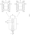
- FIG. 2 is a plan view of an upper mold and a lower mold of a notching mold according to a first embodiment of the present invention
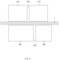
- FIG. 3 is a side view of the upper mold and the lower mold of the notching mold according to the first embodiment of the present invention
- FIG. 4 is a view illustrating a state in which the upper mold and the lower mold are closed in FIG. 3 .
- a notching mold provided in this embodiment comprises a main mold 10 and first and second auxiliary molds 20 and 30, which are additionally coupled to one side and the other side of the main mold 10, respectively.
- the main mold 10 comprises an upper mold 11 and a lower mold 12, which are parallel to each other.
- the upper mold 11 and the lower mold 12 are configured to be slidable close to or away from each other. That is, in a state in which the lower mold 12 is fixed, the upper mold 11 descends, or in a state in which the upper mold 11 is fixed, the lower mold 12 ascends. Alternatively, the upper mold 11 descends, and the lower mold 12 ascends.
- each of surfaces facing each other thereof is formed as a flat surface.
- first auxiliary mold 20 is mounted at one side of the main mold 10
- second auxiliary mold 30 is mounted at the other side of the main mold 10.
- the first auxiliary mold 20 When the electrode base material 1 is input into the main mold 10, the first auxiliary mold 20 is disposed at a position at which the non-coating portion 1a is processed at one end of the electrode base material 1.
- the first auxiliary mold comprises a first auxiliary upper mold 21 and a first auxiliary lower mold 22, and also, the first auxiliary upper mold 21 is coupled to the upper mold 11, and the first auxiliary lower mold 22 is coupled to the lower mold 12.
- the second auxiliary mold 30 When the electrode base material 1 is input into the main mold 10, the second auxiliary mold 30 is disposed at a position at which the non-coating portion 1a is processed at the other end of the electrode base material 1.
- the second auxiliary mold comprises a second auxiliary upper mold 31 and a second auxiliary lower mold 32, and also, the second auxiliary upper mold 31 is coupled to the upper mold 11 at an opposite side of the first auxiliary upper mold 21, and the second auxiliary lower mold 32 is coupled to the lower mold 12 at an opposite side of the first auxiliary lower mold 22.
- the first auxiliary mold 20 and the second auxiliary mold 30 may individually and simultaneously notch the non-coating portions 1a of the electrode base material 1. That is, the notching process performed here means all three processing, for example, ⁇ processing of molding the electrode tab', ⁇ processing of forming the electrode tab and then cutting the electrode tab into individual electrodes, or ⁇ processing of cutting the non-coating portion from the coating portion'.
- the first auxiliary upper mold 21 and the second auxiliary upper mold 31 provided in this embodiment are coupled to be detachable and adjustable in position in the upper mold 11, and the first auxiliary lower mold 21 and the second auxiliary upper mold 21 are coupled to be detachable and adjustable in position in the lower mold 12.
- the notching may be performed by adjusting or replacing only any one of the first auxiliary mold 20 and/or the second auxiliary mold 30 without replacing the entire main mold 10.
- the mold according to the related art as illustrated in FIG 1b , only one embossed part 3a and only one engraved part 4a are formed on the upper mold 3 and the lower mold 4, respectively.
- the first auxiliary mold 20 and the second auxiliary mold 30 are disposed to be separated from each other, as illustrated in FIG. 2 , the first and second auxiliary upper molds 21 and 31 and the first and second auxiliary lower molds 22 and 32 may be disposed in pairs, and thus, a plurality of embossed parts may be formed on the first auxiliary upper mold 21 and the second auxiliary upper mold 31, and a plurality of engraved parts may be formed in the first auxiliary lower mold 22 and the second auxiliary lower mold 32.
- the first auxiliary mold 20 and the second auxiliary mold 30 may perform the processing so that the plurality of electrode tabs are molded in one stroke at the same time.
- the notching mold according to the present invention may comprise a stripper 40. That is, as more clearly illustrated in FIGS. 3 and 4 , in the notching mold provided in this embodiment, when the electrode base material 1 is input between the first auxiliary mold 20 and the second auxiliary mold 30, the stripper 40 that presses and fixes the coating portion 1b disposed between both the non-coating portions 1a may be disposed.
- the stripper 40 comprises an upper stripper 41 coupled to the upper mold 11 and a lower stripper 42 coupled to the lower mold 12.
- a predetermined pressure is applied to the coating portion 1b between the upper stripper 41 and the lower stripper 42 to fix movement of the coating portion 1b.
- the upper stripper 41 comprises a main upper stripper 41a disposed at a center between the first auxiliary upper mold 21 and the second auxiliary upper mold 31 and an auxiliary upper stripper 41b disposed at one side of the main upper stripper 41 with a gap therebetween.
- the lower stripper 42 comprises a main lower stripper 42a disposed at a center between the first auxiliary lower mold 22 and the second auxiliary lower mold 32 and an auxiliary lower stripper 42b disposed at one side of the main lower stripper 42a with a gap therebetween.
- the auxiliary upper stripper 41b is disposed at each of both the sides of the main upper stripper 42a with a gap between the auxiliary upper stripper 41b and the main upper stripper 42a
- the auxiliary lower stripper 42b is disposed at each of both the sides of the main lower stripper 42a with a gap between the auxiliary lower stripper 42b and the main lower stripper 42a.
- the auxiliary upper stripper 41b and the auxiliary lower stripper 42b are detachable. That is, the auxiliary upper stripper 41b is detachably coupled to the first auxiliary upper mold 21 of the first auxiliary mold 20 or the second auxiliary upper mold 31 of the second auxiliary mold 30, and the auxiliary lower stripper 42b is detachably coupled to the first auxiliary lower mold 21 of the first auxiliary mold 20 or the second auxiliary lower mold 32 of the second auxiliary mold 30.
- FIG. 5 is an enlarged view illustrating a state in which the gap between the main upper stripper 41a and the auxiliary upper stripper 41b and the gap between the main lower stripper 42a and the auxiliary lower stripper 42b are dislocated along a vertical direction, the gaps occur between the main upper stripper 41a and the auxiliary upper stripper 41b and between main lower stripper 42a and the auxiliary lower stripper 42b.
- the gap between the main upper stripper 41a and the auxiliary upper stripper 41b and the gap between the main lower stripper 42a and the auxiliary lower stripper 42b are dislocated along the vertical direction.
- the auxiliary strippers 41b and 42b may be additionally mounted to the first auxiliary mold 20 and the second auxiliary mold 30 to additionally fix the coating portion 1b when the first auxiliary upper mold 21 and the second auxiliary lower mold 32 are slid.
- the stripper provided in this embodiment is provided to be divided into the main strippers 41a and 42a mounted on the main mold 10 and the auxiliary strippers 41b and 42b mounted on the auxiliary molds 20 and 30.
- the gap between the main upper stripper 41a and the auxiliary upper stripper 41b and the gap between the main lower stripper 42a and the auxiliary lower stripper 42b are dislocated along the vertical direction. That is, when the upper and lower gap positions are the same, both upper and lower sides may be opened to cause a possibility that the coating portion 1b is sag or be jammed between the gaps. However, when the gaps are dislocated as described above, since at least one side of both the upper and lower sides is in a blocked state, the possibility of occurrence of the sagging or jamming of the coating portion 1b between the gaps may be significantly reduced.
- the first auxiliary mold 20 and the second auxiliary mold 30 individually notch the non-coating portion 1a disposed on each of both the ends of the electrode base material 1 according to an operation of the main mold 10, the molding of both the non-coating portions 1a may be more easily performed, and larger and various types of electrode base material may be notched.
- first and second auxiliary molds 20 and 30 individually and simultaneously notch the non-coating portions, respectively, the design flexibility of processing each of the electrode tabs at both the sides may increase, and the processing position and precision may be adjusted more easily.
- the movement of the coating portion may be fixed when the notching is performed.
- the coating portion may be more stably supported by replacing only the auxiliary stripper according to the thermal expansion coefficient of the electrode base material due to the temperature.
- the gap between the main upper stripper 41a and the auxiliary upper stripper 41b and the gap between the main lower stripper 42a and the auxiliary lower stripper 42b may be dislocated along the vertical direction to prevent pressing, the marks, or the jamming from occurring on the electrode base material.
- the auxiliary strippers 41b and 42b may be detachably mounted on the first auxiliary mold 20 and the second auxiliary mold 30, and thus, the first auxiliary mold 20 and the second auxiliary mold 30 may be exchanged together with the replacement when the first auxiliary mold 20 and the second auxiliary mold 30 are replaced.
Landscapes
- Engineering & Computer Science (AREA)
- Chemical & Material Sciences (AREA)
- Chemical Kinetics & Catalysis (AREA)
- Electrochemistry (AREA)
- General Chemical & Material Sciences (AREA)
- Life Sciences & Earth Sciences (AREA)
- Forests & Forestry (AREA)
- Mechanical Engineering (AREA)
- Manufacturing & Machinery (AREA)
- Battery Electrode And Active Subsutance (AREA)
- Connection Of Batteries Or Terminals (AREA)
- Secondary Cells (AREA)
Abstract
Description
- The present application claims the benefit of the priority of
Korean Patent Application No. 10-2020-0142546, filed on October 29, 2020 - The present invention relates to a notching mold, which molds an electrode tab on an electrode base material, in which an active material is applied to a surface of a collector, wherein a non-coating portion, on which the active material is not applied, is formed on each of one end and the other end of a coating portion, on which the active material is applied, or which processes the base material as an individual electrode, on which an electrode tab is molded, and more particularly, to a notching mold that is capable of processing a plurality of individual electrodes in one stroke and capable of more easily notching electrodes having various sizes because of performing individual notching of a first auxiliary mold and a second auxiliary mold, which are mounted in a main mold.
- In general, secondary batteries refer to chargeable and dischargeable batteries, unlike primary batteries that are not chargeable. The secondary batteries are being widely used in the high-tech electronic fields such as mobile phones, notebook computers, and camcorders.
- Such a secondary battery is classified into a can type secondary battery in which an electrode assembly is built in a metal can and a pouch type secondary battery in which an electrode assembly is built in a pouch. The pouch type secondary battery comprises an electrode assembly, an electrolyte, and a pouch accommodating the electrode assembly and the electrolyte. Also, the electrode assembly has a structure in which a plurality of electrodes and a plurality of separators are alternately stacked.
- Referring to
FIG. 1a , which illustrates processing of individual electrodes in anelectrode base material 1, a positive electrode base material or a negative electrode base material, which is processed using a notching mold, is provided in a state in which a positive electrode active material or a negative electrode active material is applied in a longitudinal direction of a positive electrode collector or a negative electrode collector except for a portion of each of both ends thereof. - In addition, when the electrode base material is input between notching molds as illustrated in
FIG. 1b that illustrates an upper mold and a lower mold of a notching mold according to the related art, anon-coating portion 1a formed on one end or each of both ends of acoating portion 1b of anelectrode base material 1 is processed as anelectrode tab 2a by pressing of an embossed part 3a and an engravedpart 4a, which are engaged with each other when anupper mold 3 and alower mold 4 are closed. - Here, cutting into
individual electrodes 2 may also be performed together with the processing of thenon-coating portion 1a by the notching mold or a separate cutting device. That is, it is processed into theindividual electrodes 2 having shapes as illustrated in followingFIG. 1a . - That is, the notching performed in the notching mold means `cut off', for example, means processing of cutting an unnecessary portion of the
non-coating portion 1a to form theelectrode tab 2a, processing of forming theelectrode tab 2a and cutting thebase material 1 by a predetermined length to form theindividual electrodes 2, or processing of cutting the entirenon-coating portion 1a at one side. Thecoating portion 1b of theelectrode base material 1 is cut into thecoating portion 2b of each of theindividual electrodes 2 having a predetermined size. - In the notching mold according to the related art, when an
electrode base material 1 having a different size is input, there is a problem that both theupper mold 3 and thelower mold 4 are exchanged, or a processableelectrode base material 1 is limited in size. In addition, since it is difficult to individually adjust a plurality of embossed parts 3a and engravedparts 4a in order to process a plurality ofelectrode tabs 2a in one stroke by forming the plurality of embossed parts 3a and engravedparts 4a, and there is a problem that a processing deviation increases, there is difficult to be applied in practice. - Therefore, in order to solve the problems of the structure according to the related art, a main object of the present invention is to provide a notching mold that is capable of individually processing both electrode tabs and adjusting individual setting during the processing.
- A notching mold, which molds a non-coating portion when an electrode base material, in which an active material is applied to a surface of a collector, is input, wherein the non-coating portion, on which the active material is not applied, is formed on each of one end and the other end of a coating portion, on which the active material is applied, according to the present invention for achieving the above object comprises: a main mold comprising an upper mold and a lower mold, which are parallel to each other, wherein the upper mold and the lower mold are slidable close to or away from each other; a first auxiliary mold configured so that, when the electrode base material is input into the main mold, the non-coating portion on one end of the electrode base material is disposed at a processible position, the first auxiliary mold comprising a first auxiliary upper mold coupled to the upper mold and a first auxiliary lower mold coupled to the lower mold; and a second auxiliary mold configured so that, when the electrode base material is input into the main mold, the non-coating portion on the other end of the electrode base material is disposed at a processible position, the second auxiliary mold comprising a second auxiliary upper mold coupled to the upper mold and a second auxiliary lower mold coupled to the lower mold.
- When the upper mold and the lower mold of the main mold are slid, the sliding of the first auxiliary upper mold and the first auxiliary lower mold of the first auxiliary mold and the sliding of the second auxiliary upper mold and the second auxiliary lower mold of the second auxiliary mold may be performed at the same time to individually and respectively notch the non-coating portions of the fist auxiliary mold and the second auxiliary mold at the same time (here, the notching process comprises the following meanings. That is, the notching process comprises `forming of an electrode tab', 'forming of an electrode tab and cutting the electrode tab into individual electrodes' or 'cutting of the non-coating portion').
- The first auxiliary upper mold and the second auxiliary upper mold may be coupled to be detachable and adjustable in position in the upper mold, and the first auxiliary lower mold and the second auxiliary upper mold may be coupled to be detachable and adjustable in position in the lower mold.
- When the electrode base material is input into the main mold, the first auxiliary mold and the second auxiliary mold may perform the processing so that the plurality of electrode tabs are molded in one stroke.
- A stripper that presses and fixes the coating portion when the electrode base material is input may be disposed between the first auxiliary mold and the second auxiliary mold.
- The stripper may comprise an upper stripper coupled to the upper mold and a lower stripper coupled to the lower mold, wherein, when the non-coating portions are molded using the first auxiliary mold and the second auxiliary mold, a predetermined pressure may be applied to the coating portion between the upper stripper and the lower stripper to fix movement of the coating portion.
- The upper stripper may comprise a main upper stripper disposed at a center between the first auxiliary upper mold and the second auxiliary upper mold and an auxiliary upper stripper disposed at one side of the main upper stripper with a gap therebetween, and the lower stripper may comprise a main lower stripper disposed at a center between the first auxiliary lower mold and the second auxiliary lower mold and an auxiliary lower stripper disposed at one side of the main lower stripper with a gap therebetween.
- The auxiliary upper stripper may be disposed at each of both the sides of the main upper stripper with a gap therebetween, and the auxiliary lower stripper may be disposed at each of both the sides of the main lower stripper with a gap therebetween.
- Each of the auxiliary upper stripper and the auxiliary lower stripper may be detachable. The auxiliary upper stripper may be detachably coupled to the first auxiliary upper mold of the first auxiliary mold or the second auxiliary upper mold of the second auxiliary mold, and the auxiliary lower stripper may be detachably coupled to the first auxiliary lower mold of the first auxiliary mold or the second auxiliary lower mold of the second auxiliary mold.
- The gap between the main upper stripper and the auxiliary upper stripper and the gap between the main lower stripper and the auxiliary lower stripper may be dislocated along a vertical direction.
- In the present invention having the above configuration, since the first and second auxiliary molds individually notch the non-coating portions disposed at both the ends of the electrode base material, both the non-coating portions may be more easily molded, and the larger and various types of electrode base materials may be notched.
- Since the first and second auxiliary molds individually and simultaneously notch the non-coating portions, respectively, the design flexibility of processing each of the electrode tabs at both the sides may increase, and the processing position and precision may be adjusted more easily.
- In the notching mold according to the present invention, since the stripper is provided, the movement of the coating portion may be fixed when the notching is performed.
- Since the stripper is divided into the main stripper (the main upper stripper and the main lower stripper) and the auxiliary stripper (the auxiliary upper stripper and the auxiliary lower stripper), the coating portion may be more stably supported by replacing only the auxiliary stripper according to the thermal expansion coefficient of the electrode base material due to the temperature.
- Furthermore, the gap between the main upper stripper and the auxiliary upper stripper and the gap between the main lower stripper and the auxiliary lower stripper may be dislocated along the vertical direction to prevent pressing, the marks, or the jamming from occurring on the electrode base material. The auxiliary stripper may be detachably mounted on the first auxiliary mold and the second auxiliary mold and thus may be easily exchanged together when replacing the first auxiliary mold and the second auxiliary mold.
-
-
FIG. 1a is a view illustrating a state of being notched into individual electrodes in an electrode base material. -
FIG. 1b is a view illustrating shapes of an upper mold and a lower mold of a notching mold according to a related art. -
FIG. 2 is a plan view of an upper mold and a lower mold of a notching mold according to a first embodiment of the present invention. -
FIG. 3 is a side view of the upper mold and the lower mold of the notching mold according to the first embodiment of the present invention. -
FIG. 4 is a view illustrating a state in which the upper mold and the lower mold are closed inFIG. 3 . -
FIG. 5 is an enlarged view illustrating a state in which a gap between a main upper stripper and an auxiliary upper stripper and a gap between a main lower stripper and an auxiliary lower stripper are dislocated along a vertical direction. - Hereinafter, preferred embodiments of the present invention will be described in detail with reference to the accompanying drawings in such a manner that the technical idea of the present invention may easily be carried out by a person with ordinary skill in the art to which the invention pertains. The present invention may, however, be embodied in different forms and should not be construed as limited to the embodiments set forth herein.
- In order to clearly describe the present invention, parts irrelevant to the description are omitted, and the same reference numerals are assigned to the same or similar components throughout the specification.
- Also, terms or words used in this specification and claims should not be restrictively interpreted as ordinary meanings or dictionary-based meanings, but should be interpreted as meanings and concepts conforming to the scope of the present invention on the basis of the principle that an inventor can properly define the concept of a term to describe and explain his or her invention in the best ways.
- The present invention relates to a notching mold that notches a non-coating portion (molds an electrode tab on the non-coating portion) when an
electrode base material 1 is input so that thebase material 1, in which an active material is applied to a surface of a collector, wherein a non-coating portion, on which the active material is not applied, is formed on each of one end and the other end of acoating portion 1b, on which the active material is applied, is notched intoindividual electrodes 2, on which anelectrode tab 2a is formed on each of both ends or one end of the non-coatingportion 2b. Hereinafter, embodiments according to the present invention will be described with reference to the accompanying drawings. -
FIG. 2 is a plan view of an upper mold and a lower mold of a notching mold according to a first embodiment of the present invention,FIG. 3 is a side view of the upper mold and the lower mold of the notching mold according to the first embodiment of the present invention, andFIG. 4 is a view illustrating a state in which the upper mold and the lower mold are closed inFIG. 3 . - Referring to the accompanying drawings, a notching mold provided in this embodiment comprises a
main mold 10 and first and secondauxiliary molds main mold 10, respectively. - As illustrated in
FIG. 2 , themain mold 10 comprises anupper mold 11 and alower mold 12, which are parallel to each other. Theupper mold 11 and thelower mold 12 are configured to be slidable close to or away from each other. That is, in a state in which thelower mold 12 is fixed, theupper mold 11 descends, or in a state in which theupper mold 11 is fixed, thelower mold 12 ascends. Alternatively, theupper mold 11 descends, and thelower mold 12 ascends. Here, each of surfaces facing each other thereof is formed as a flat surface. - In addition, the first
auxiliary mold 20 is mounted at one side of themain mold 10, and the secondauxiliary mold 30 is mounted at the other side of themain mold 10. - When the
electrode base material 1 is input into themain mold 10, the firstauxiliary mold 20 is disposed at a position at which thenon-coating portion 1a is processed at one end of theelectrode base material 1. The first auxiliary mold comprises a first auxiliaryupper mold 21 and a first auxiliarylower mold 22, and also, the first auxiliaryupper mold 21 is coupled to theupper mold 11, and the first auxiliarylower mold 22 is coupled to thelower mold 12. - When the
electrode base material 1 is input into themain mold 10, the secondauxiliary mold 30 is disposed at a position at which thenon-coating portion 1a is processed at the other end of theelectrode base material 1. The second auxiliary mold comprises a second auxiliaryupper mold 31 and a second auxiliarylower mold 32, and also, the second auxiliaryupper mold 31 is coupled to theupper mold 11 at an opposite side of the first auxiliaryupper mold 21, and the second auxiliarylower mold 32 is coupled to thelower mold 12 at an opposite side of the first auxiliarylower mold 22. - Thus, when the
upper mold 11 and thelower mold 12 of themain mold 10 are slid, the sliding of the first auxiliaryupper mold 21 and the first auxiliarylower mold 22 of the firstauxiliary mold 20 and the sliding of the second auxiliaryupper mold 31 and the second auxiliarylower mold 32 of the secondauxiliary mold 30 are performed at the same time. - Thus, the first
auxiliary mold 20 and the secondauxiliary mold 30 may individually and simultaneously notch thenon-coating portions 1a of theelectrode base material 1. That is, the notching process performed here means all three processing, for example, `processing of molding the electrode tab', `processing of forming the electrode tab and then cutting the electrode tab into individual electrodes, or `processing of cutting the non-coating portion from the coating portion'. - The first auxiliary
upper mold 21 and the second auxiliaryupper mold 31 provided in this embodiment are coupled to be detachable and adjustable in position in theupper mold 11, and the first auxiliarylower mold 21 and the second auxiliaryupper mold 21 are coupled to be detachable and adjustable in position in thelower mold 12. - Thus, when it is necessary to adjust a size or position of the electrode tab according to a size of the
electrode base material 1 on which the notching is performed, the notching may be performed by adjusting or replacing only any one of the firstauxiliary mold 20 and/or the secondauxiliary mold 30 without replacing the entiremain mold 10. - In addition, in the mold according to the related art, as illustrated in
FIG 1b , only one embossed part 3a and only oneengraved part 4a are formed on theupper mold 3 and thelower mold 4, respectively. However, in the mold provided in the present invention, since the firstauxiliary mold 20 and the secondauxiliary mold 30 are disposed to be separated from each other, as illustrated inFIG. 2 , the first and second auxiliaryupper molds lower molds upper mold 21 and the second auxiliaryupper mold 31, and a plurality of engraved parts may be formed in the first auxiliarylower mold 22 and the second auxiliarylower mold 32. - Thus, in the notching mold provided in this embodiment, when the
electrode base material 1 is input into themain mold 10, the firstauxiliary mold 20 and the secondauxiliary mold 30 may perform the processing so that the plurality of electrode tabs are molded in one stroke at the same time. - Furthermore, the notching mold according to the present invention may comprise a
stripper 40. That is, as more clearly illustrated inFIGS. 3 and4 , in the notching mold provided in this embodiment, when theelectrode base material 1 is input between the firstauxiliary mold 20 and the secondauxiliary mold 30, thestripper 40 that presses and fixes thecoating portion 1b disposed between both thenon-coating portions 1a may be disposed. - The
stripper 40 comprises anupper stripper 41 coupled to theupper mold 11 and alower stripper 42 coupled to thelower mold 12. When the non-coating portions are molded using the firstauxiliary mold 20 and the secondauxiliary mold 30, a predetermined pressure is applied to thecoating portion 1b between theupper stripper 41 and thelower stripper 42 to fix movement of thecoating portion 1b. - The
upper stripper 41 comprises a mainupper stripper 41a disposed at a center between the first auxiliaryupper mold 21 and the second auxiliaryupper mold 31 and an auxiliaryupper stripper 41b disposed at one side of the mainupper stripper 41 with a gap therebetween. - Also, the
lower stripper 42 comprises a mainlower stripper 42a disposed at a center between the first auxiliarylower mold 22 and the second auxiliarylower mold 32 and an auxiliarylower stripper 42b disposed at one side of the mainlower stripper 42a with a gap therebetween. - Here, the auxiliary
upper stripper 41b is disposed at each of both the sides of the mainupper stripper 42a with a gap between the auxiliaryupper stripper 41b and the mainupper stripper 42a, and the auxiliarylower stripper 42b is disposed at each of both the sides of the mainlower stripper 42a with a gap between the auxiliarylower stripper 42b and the mainlower stripper 42a. - The auxiliary
upper stripper 41b and the auxiliarylower stripper 42b are detachable. That is, the auxiliaryupper stripper 41b is detachably coupled to the first auxiliaryupper mold 21 of the firstauxiliary mold 20 or the second auxiliaryupper mold 31 of the secondauxiliary mold 30, and the auxiliarylower stripper 42b is detachably coupled to the first auxiliarylower mold 21 of the firstauxiliary mold 20 or the second auxiliarylower mold 32 of the secondauxiliary mold 30. - Furthermore, referring to
FIG. 5 that is an enlarged view illustrating a state in which the gap between the mainupper stripper 41a and the auxiliaryupper stripper 41b and the gap between the mainlower stripper 42a and the auxiliarylower stripper 42b are dislocated along a vertical direction, the gaps occur between the mainupper stripper 41a and the auxiliaryupper stripper 41b and between mainlower stripper 42a and the auxiliarylower stripper 42b. - Here, the gap between the main
upper stripper 41a and the auxiliaryupper stripper 41b and the gap between the mainlower stripper 42a and the auxiliarylower stripper 42b are dislocated along the vertical direction. - That is, as a width of the
electrode base material 1 increases (a distance between the non-coating portions on both ends increases), it is difficult to efficiently fix thecoating portion 1b by using one fixed stripper due to an impact and thermal expansion applied during the processing. - Also, when only one
main stripper coating portion 1b occurs in the vicinity of the firstauxiliary mold 20 and the secondauxiliary mold 30, in which the processing is performed. Therefore, theauxiliary strippers auxiliary mold 20 and the secondauxiliary mold 30 to additionally fix thecoating portion 1b when the first auxiliaryupper mold 21 and the second auxiliarylower mold 32 are slid. - For the above reasons, the stripper provided in this embodiment is provided to be divided into the
main strippers main mold 10 and theauxiliary strippers auxiliary molds - Furthermore, as described above, in this embodiment, the gap between the main
upper stripper 41a and the auxiliaryupper stripper 41b and the gap between the mainlower stripper 42a and the auxiliarylower stripper 42b are dislocated along the vertical direction. That is, when the upper and lower gap positions are the same, both upper and lower sides may be opened to cause a possibility that thecoating portion 1b is sag or be jammed between the gaps. However, when the gaps are dislocated as described above, since at least one side of both the upper and lower sides is in a blocked state, the possibility of occurrence of the sagging or jamming of thecoating portion 1b between the gaps may be significantly reduced. - In the present invention having the above configuration, since the first
auxiliary mold 20 and the secondauxiliary mold 30 individually notch thenon-coating portion 1a disposed on each of both the ends of theelectrode base material 1 according to an operation of themain mold 10, the molding of both thenon-coating portions 1a may be more easily performed, and larger and various types of electrode base material may be notched. - Since the first and second
auxiliary molds - In the notching mold according to the present invention, since the
stripper 40 is provided, the movement of the coating portion may be fixed when the notching is performed. - Since the stripper is divided into the main stripper (the main upper stripper and the main lower stripper) and the auxiliary stripper (the auxiliary upper stripper and the auxiliary lower stripper), the coating portion may be more stably supported by replacing only the auxiliary stripper according to the thermal expansion coefficient of the electrode base material due to the temperature.
- Furthermore, the gap between the main
upper stripper 41a and the auxiliaryupper stripper 41b and the gap between the mainlower stripper 42a and the auxiliarylower stripper 42b may be dislocated along the vertical direction to prevent pressing, the marks, or the jamming from occurring on the electrode base material. Theauxiliary strippers auxiliary mold 20 and the secondauxiliary mold 30, and thus, the firstauxiliary mold 20 and the secondauxiliary mold 30 may be exchanged together with the replacement when the firstauxiliary mold 20 and the secondauxiliary mold 30 are replaced. - While the embodiments of the present invention have been described with reference to the specific embodiments, it will be apparent to those skilled in the art that various changes and modifications may be made without departing from the spirit and scope of the invention as defined in the following claims.
-
- 1:
- Electrode base material
- 1a:
- Non-coating portion
- 1b:
- Coating portion
- 2a:
- Electrode tab
- 10:
- Main mold
- 11:
- Upper mold
- 12:
- Lower mold
- 20:
- First auxiliary mold
- 30:
- Second auxiliary mold
- 40:
- Stripper
Claims (11)
- A notching mold, which molds a non-coating portion when an electrode base material, in which an active material is applied to a surface of a collector, is input, wherein the non-coating portion, on which the active material is not applied, is formed on each of one end and the other end of a coating portion, on which the active material is applied, the notching mold comprising:a main mold comprising an upper mold and a lower mold, which are parallel to each other, wherein the upper mold and the lower mold are slidable close to or away from each other;a first auxiliary mold configured so that, when the electrode base material is input into the main mold, the non-coating portion on one end of the electrode base material is disposed at a processible position, the first auxiliary mold comprising a first auxiliary upper mold coupled to the upper mold and a first auxiliary lower mold coupled to the lower mold; anda second auxiliary mold configured so that, when the electrode base material is input into the main mold, the non-coating portion on the other end of the electrode base material is disposed at a processible position, the second auxiliary mold comprising a second auxiliary upper mold coupled to the upper mold and a second auxiliary lower mold coupled to the lower mold.
- The notching mold of claim 1, wherein, when the upper mold and the lower mold of the main mold are slid, the sliding of the first auxiliary upper mold and the first auxiliary lower mold of the first auxiliary mold and the sliding of the second auxiliary upper mold and the second auxiliary lower mold of the second auxiliary mold are performed at the same time to individually and respectively notch the non-coating portions of the fist auxiliary mold and the second auxiliary mold at the same time.
- The notching mold of claim 1, wherein the first auxiliary upper mold and the second auxiliary upper mold are coupled to be detachable and adjustable in position in the upper mold, and the first auxiliary lower mold and the second auxiliary upper mold are coupled to be detachable and adjustable in position in the lower mold.
- The notching mold of claim 1, wherein, when the electrode base material is input into the main mold, the first auxiliary mold and the second auxiliary mold perform the processing so that the plurality of electrode tabs are molded in one stroke.
- The notching mold of claim 1, wherein a stripper that presses and fixes the coating portion when the electrode base material is input is disposed between the first auxiliary mold and the second auxiliary mold.
- The notching mold of claim 5, wherein the stripper comprises an upper stripper coupled to the upper mold and a lower stripper coupled to the lower mold,
wherein, when the non-coating portions are molded using the first auxiliary mold and the second auxiliary mold, a predetermined pressure is applied to the coating portion between the upper stripper and the lower stripper to fix movement of the coating portion. - The notching mold of claim 6, wherein the upper stripper comprises a main upper stripper disposed at a center between the first auxiliary upper mold and the second auxiliary upper mold and an auxiliary upper stripper disposed at one side of the main upper stripper with a gap therebetween, and
the lower stripper comprises a main lower stripper disposed at a center between the first auxiliary lower mold and the second auxiliary lower mold and an auxiliary lower stripper disposed at one side of the main lower stripper with a gap therebetween. - The notching mold of claim 7, wherein the auxiliary upper stripper is disposed at each of both the sides of the main upper stripper with a gap therebetween, and
the auxiliary lower stripper is disposed at each of both the sides of the main lower stripper with a gap therebetween. - The notching mold of claim 7, wherein each of the auxiliary upper stripper and the auxiliary lower stripper is detachable.
- The notching mold of claim 7, wherein the auxiliary upper stripper is detachably coupled to the first auxiliary upper mold of the first auxiliary mold or the second auxiliary upper mold of the second auxiliary mold, and
the auxiliary lower stripper is detachably coupled to the first auxiliary lower mold of the first auxiliary mold or the second auxiliary lower mold of the second auxiliary mold. - The notching mold of claim 7, wherein the gap between the main upper stripper and the auxiliary upper stripper and the gap between the main lower stripper and the auxiliary lower stripper are dislocated along a vertical direction.
Applications Claiming Priority (2)
| Application Number | Priority Date | Filing Date | Title |
|---|---|---|---|
| KR1020200142546A KR102807063B1 (en) | 2020-10-29 | 2020-10-29 | Mold for notching |
| PCT/KR2021/015046 WO2022092739A1 (en) | 2020-10-29 | 2021-10-25 | Notching mold |
Publications (3)
| Publication Number | Publication Date |
|---|---|
| EP4239702A1 true EP4239702A1 (en) | 2023-09-06 |
| EP4239702A4 EP4239702A4 (en) | 2024-04-24 |
| EP4239702B1 EP4239702B1 (en) | 2026-01-28 |
Family
ID=81382808
Family Applications (1)
| Application Number | Title | Priority Date | Filing Date |
|---|---|---|---|
| EP21886733.1A Active EP4239702B1 (en) | 2020-10-29 | 2021-10-25 | Notching mold |
Country Status (5)
| Country | Link |
|---|---|
| US (1) | US12390949B2 (en) |
| EP (1) | EP4239702B1 (en) |
| KR (1) | KR102807063B1 (en) |
| CN (1) | CN116325338A (en) |
| WO (1) | WO2022092739A1 (en) |
Families Citing this family (1)
| Publication number | Priority date | Publication date | Assignee | Title |
|---|---|---|---|---|
| CN117564169A (en) * | 2023-10-26 | 2024-02-20 | 合肥国轩电池科技有限公司 | A device and method for embossing battery pole pieces |
Family Cites Families (22)
| Publication number | Priority date | Publication date | Assignee | Title |
|---|---|---|---|---|
| US2127131A (en) * | 1937-04-16 | 1938-08-16 | Mary R Claff | Die for the production of box blanks |
| US3880038A (en) * | 1973-05-25 | 1975-04-29 | James Mangos | Sandwich die set |
| KR100696892B1 (en) * | 2002-05-03 | 2007-03-20 | 주식회사 에스에프에이 | Electrode plate lamination and assembly system of polymer secondary battery |
| KR100908573B1 (en) | 2009-02-03 | 2009-07-22 | 안혁 | Pole plate processing unit of lithium ion polymer battery for hybrid vehicle |
| DE202009012050U1 (en) * | 2009-09-07 | 2009-11-19 | LIN, Zhi-qin | Mold arrangement for a pipe section |
| CN201816936U (en) * | 2010-08-30 | 2011-05-04 | 冠捷显示科技(武汉)有限公司 | Compression resisting EPE buffer |
| KR101307875B1 (en) * | 2012-01-30 | 2013-09-13 | 주식회사 엠플러스 | Secondary battery electrode panel stamping apparatus |
| KR101814863B1 (en) * | 2014-12-24 | 2018-01-04 | 주식회사 엘지화학 | Notching mold |
| KR102023735B1 (en) | 2015-09-03 | 2019-09-20 | 주식회사 엘지화학 | Notching Apparatus Having Integral Die and Stripper |
| KR101737790B1 (en) | 2016-07-15 | 2017-05-19 | 안혁 | A Press Mold Device of manufacturing cell ploeplate for hybrid electric vehicle |
| KR101857096B1 (en) * | 2016-08-01 | 2018-05-11 | 안혁 | A Manufacturing Device of a Cell Poleplate |
| KR101691937B1 (en) | 2016-08-16 | 2017-01-02 | 안혁 | A Manufacturing Device of a Cell Poleplate |
| KR101943634B1 (en) * | 2017-12-29 | 2019-01-29 | 신현집 | Blanking mold for punching lithium secondary battery equipped with punch cooling means |
| KR102354280B1 (en) | 2018-02-08 | 2022-01-21 | 주식회사 엘지에너지솔루션 | Notching Apparatus and method for Secondary Battery |
| KR102309536B1 (en) | 2018-03-07 | 2021-10-07 | 주식회사 엘지에너지솔루션 | Electrode notching apparatus and method |
| KR102217450B1 (en) * | 2018-05-31 | 2021-02-22 | 주식회사 엘지화학 | Notching Apparatus and method for Secondary Battery |
| KR102145494B1 (en) * | 2018-11-23 | 2020-08-18 | 주식회사 엘지화학 | Pouch forming device and method, producing facility of secondary battery including the same |
| KR102131335B1 (en) | 2018-12-11 | 2020-07-08 | 주식회사 테크아이 | Notching system for improving machining precision |
| KR102197531B1 (en) | 2019-02-14 | 2020-12-31 | 유일에너테크(주) | System for producing electrodes of battery |
| CN110315595B (en) * | 2019-07-03 | 2024-07-05 | 重庆市维都利新能源有限公司 | Arc-shaped trimming device for soft-package lithium ion battery |
| KR102102717B1 (en) | 2019-07-29 | 2020-06-01 | 주식회사 지에스피컴퍼니 | Cutting equipment for plate |
| CN211729485U (en) * | 2019-10-15 | 2020-10-23 | 株式会社大元精密 | Mold device for processing multi-stage battery pole plate |
-
2020
- 2020-10-29 KR KR1020200142546A patent/KR102807063B1/en active Active
-
2021
- 2021-10-25 CN CN202180063662.1A patent/CN116325338A/en active Pending
- 2021-10-25 EP EP21886733.1A patent/EP4239702B1/en active Active
- 2021-10-25 US US18/030,590 patent/US12390949B2/en active Active
- 2021-10-25 WO PCT/KR2021/015046 patent/WO2022092739A1/en not_active Ceased
Also Published As
| Publication number | Publication date |
|---|---|
| US12390949B2 (en) | 2025-08-19 |
| US20240017437A1 (en) | 2024-01-18 |
| EP4239702B1 (en) | 2026-01-28 |
| KR102807063B1 (en) | 2025-05-14 |
| WO2022092739A1 (en) | 2022-05-05 |
| KR20220057367A (en) | 2022-05-09 |
| CN116325338A (en) | 2023-06-23 |
| EP4239702A4 (en) | 2024-04-24 |
Similar Documents
| Publication | Publication Date | Title |
|---|---|---|
| US11179862B2 (en) | Notching apparatus and method for secondary battery | |
| EP3561899A1 (en) | Secondary battery pouch sheath material, pouch-type secondary battery employing same, and method for manufacturing same | |
| EP2985805B1 (en) | Curved secondary battery and method of manufacturing the same | |
| US11438998B2 (en) | Plasma generating apparatus for secondary battery and lamination system comprising the same | |
| EP4239702B1 (en) | Notching mold | |
| EP3735110A1 (en) | Plasma generating apparatus for secondary battery | |
| US20230048295A1 (en) | Apparatus and Method for Pressing Secondary Battery | |
| US12512554B2 (en) | Method of manufacturing pouch-shaped battery case having venting guide portion formed therein and pouch-shaped battery case manufactured by the method | |
| US20080174006A1 (en) | Semiconductor device and method of manufacturing the same | |
| KR102261506B1 (en) | Notching Device Having Suction Pad for Fixing of Electrode Sheet | |
| EP4135064A1 (en) | Electrode drying device | |
| KR20030093362A (en) | Roll folding apparatus of polymer battery | |
| KR20220008773A (en) | Cutting device and method for electrode, producing facility of electrode including the same | |
| EP4183539B1 (en) | Apparatus and method for cutting electrode, and electrode manufacturing equipment including same | |
| US20250007123A1 (en) | Battery pack | |
| US20250300191A1 (en) | Method for Forming a Polar Plate of a Fuel Cell, and Associated Forming Plant | |
| CN112441731A (en) | Camera glass splitting jig and splitting process | |
| EP4663322A1 (en) | Electrode plate notching device | |
| CN116921759B (en) | Cutting device, cutting method and cutting equipment | |
| US20250286111A1 (en) | Pressing apparatus for secondary batteries, secondary battery manufactured using the same, and method of manufacturing the same | |
| KR20220126349A (en) | Manufacturing method of pocketing anode body and pocketing anode body | |
| EP4485554A1 (en) | Electrode cutting device and method | |
| KR102729050B1 (en) | Electrode plate transfer device for secondary battery | |
| KR20250052575A (en) | Apparatus of stacking cell | |
| JP3997974B2 (en) | Method for producing lead-acid battery |
Legal Events
| Date | Code | Title | Description |
|---|---|---|---|
| STAA | Information on the status of an ep patent application or granted ep patent |
Free format text: STATUS: THE INTERNATIONAL PUBLICATION HAS BEEN MADE |
|
| PUAI | Public reference made under article 153(3) epc to a published international application that has entered the european phase |
Free format text: ORIGINAL CODE: 0009012 |
|
| STAA | Information on the status of an ep patent application or granted ep patent |
Free format text: STATUS: REQUEST FOR EXAMINATION WAS MADE |
|
| 17P | Request for examination filed |
Effective date: 20230315 |
|
| AK | Designated contracting states |
Kind code of ref document: A1 Designated state(s): AL AT BE BG CH CY CZ DE DK EE ES FI FR GB GR HR HU IE IS IT LI LT LU LV MC MK MT NL NO PL PT RO RS SE SI SK SM TR |
|
| DAV | Request for validation of the european patent (deleted) | ||
| DAX | Request for extension of the european patent (deleted) | ||
| A4 | Supplementary search report drawn up and despatched |
Effective date: 20240321 |
|
| RIC1 | Information provided on ipc code assigned before grant |
Ipc: B26D 7/02 20060101ALN20240315BHEP Ipc: B26D 7/01 20060101ALI20240315BHEP Ipc: B26F 1/40 20060101ALI20240315BHEP Ipc: B26F 1/44 20060101ALI20240315BHEP Ipc: B26F 1/12 20060101ALI20240315BHEP Ipc: H01M 50/531 20210101ALI20240315BHEP Ipc: H01M 4/04 20060101AFI20240315BHEP |
|
| STAA | Information on the status of an ep patent application or granted ep patent |
Free format text: STATUS: EXAMINATION IS IN PROGRESS |
|
| 17Q | First examination report despatched |
Effective date: 20250530 |
|
| GRAP | Despatch of communication of intention to grant a patent |
Free format text: ORIGINAL CODE: EPIDOSNIGR1 |
|
| STAA | Information on the status of an ep patent application or granted ep patent |
Free format text: STATUS: GRANT OF PATENT IS INTENDED |
|
| RIC1 | Information provided on ipc code assigned before grant |
Ipc: B26F 1/44 20060101ALI20250807BHEP Ipc: B26F 1/40 20060101ALI20250807BHEP Ipc: B26D 7/01 20060101ALI20250807BHEP Ipc: H01M 10/04 20060101ALI20250807BHEP Ipc: B26D 7/02 20060101ALN20250807BHEP Ipc: H01M 4/04 20060101AFI20250807BHEP Ipc: H01M 50/531 20210101ALI20250807BHEP Ipc: B26F 1/12 20060101ALI20250807BHEP |
|
| INTG | Intention to grant announced |
Effective date: 20250820 |
|
| P01 | Opt-out of the competence of the unified patent court (upc) registered |
Free format text: CASE NUMBER: UPC_APP_9465_4239702/2025 Effective date: 20251009 |
|
| GRAS | Grant fee paid |
Free format text: ORIGINAL CODE: EPIDOSNIGR3 |
|
| GRAA | (expected) grant |
Free format text: ORIGINAL CODE: 0009210 |
|
| STAA | Information on the status of an ep patent application or granted ep patent |
Free format text: STATUS: THE PATENT HAS BEEN GRANTED |
|
| AK | Designated contracting states |
Kind code of ref document: B1 Designated state(s): AL AT BE BG CH CY CZ DE DK EE ES FI FR GB GR HR HU IE IS IT LI LT LU LV MC MK MT NL NO PL PT RO RS SE SI SK SM TR |
|
| REG | Reference to a national code |
Ref country code: CH Ref legal event code: F10 Free format text: ST27 STATUS EVENT CODE: U-0-0-F10-F00 (AS PROVIDED BY THE NATIONAL OFFICE) Effective date: 20260128 Ref country code: GB Ref legal event code: FG4D |
|
| REG | Reference to a national code |
Ref country code: DE Ref legal event code: R096 Ref document number: 602021047309 Country of ref document: DE |
|
| REG | Reference to a national code |
Ref country code: IE Ref legal event code: FG4D |