EP4239635B1 - Audiocodierungsvorrichtung und -verfahren - Google Patents
Audiocodierungsvorrichtung und -verfahren Download PDFInfo
- Publication number
- EP4239635B1 EP4239635B1 EP23187229.2A EP23187229A EP4239635B1 EP 4239635 B1 EP4239635 B1 EP 4239635B1 EP 23187229 A EP23187229 A EP 23187229A EP 4239635 B1 EP4239635 B1 EP 4239635B1
- Authority
- EP
- European Patent Office
- Prior art keywords
- unit
- auxiliary information
- transient
- power
- audio
- Prior art date
- Legal status (The legal status is an assumption and is not a legal conclusion. Google has not performed a legal analysis and makes no representation as to the accuracy of the status listed.)
- Active
Links
Images


Classifications
-
- G—PHYSICS
- G10—MUSICAL INSTRUMENTS; ACOUSTICS
- G10L—SPEECH ANALYSIS TECHNIQUES OR SPEECH SYNTHESIS; SPEECH RECOGNITION; SPEECH OR VOICE PROCESSING TECHNIQUES; SPEECH OR AUDIO CODING OR DECODING
- G10L19/00—Speech or audio signals analysis-synthesis techniques for redundancy reduction, e.g. in vocoders; Coding or decoding of speech or audio signals, using source filter models or psychoacoustic analysis
- G10L19/005—Correction of errors induced by the transmission channel, if related to the coding algorithm
-
- G—PHYSICS
- G10—MUSICAL INSTRUMENTS; ACOUSTICS
- G10L—SPEECH ANALYSIS TECHNIQUES OR SPEECH SYNTHESIS; SPEECH RECOGNITION; SPEECH OR VOICE PROCESSING TECHNIQUES; SPEECH OR AUDIO CODING OR DECODING
- G10L25/00—Speech or voice analysis techniques not restricted to a single one of groups G10L15/00 - G10L21/00
- G10L25/03—Speech or voice analysis techniques not restricted to a single one of groups G10L15/00 - G10L21/00 characterised by the type of extracted parameters
- G10L25/21—Speech or voice analysis techniques not restricted to a single one of groups G10L15/00 - G10L21/00 characterised by the type of extracted parameters the extracted parameters being power information
-
- G—PHYSICS
- G10—MUSICAL INSTRUMENTS; ACOUSTICS
- G10L—SPEECH ANALYSIS TECHNIQUES OR SPEECH SYNTHESIS; SPEECH RECOGNITION; SPEECH OR VOICE PROCESSING TECHNIQUES; SPEECH OR AUDIO CODING OR DECODING
- G10L19/00—Speech or audio signals analysis-synthesis techniques for redundancy reduction, e.g. in vocoders; Coding or decoding of speech or audio signals, using source filter models or psychoacoustic analysis
- G10L19/02—Speech or audio signals analysis-synthesis techniques for redundancy reduction, e.g. in vocoders; Coding or decoding of speech or audio signals, using source filter models or psychoacoustic analysis using spectral analysis, e.g. transform vocoders or subband vocoders
- G10L19/022—Blocking, i.e. grouping of samples in time; Choice of analysis windows; Overlap factoring
- G10L19/025—Detection of transients or attacks for time/frequency resolution switching
Definitions
- the present invention relates to error concealment in transmission of audio packets containing audio codes obtained by encoding an audio signal consisting of a plurality of frames, via an IP network or a mobile communication network and, more particularly, to an audio encoding device and audio encoding method to implement the error concealment.
- an audio or acoustic signal (which will be generally referred to as an "audio signal") via an IP network or mobile communication
- the audio signal is encoded to be expressed by a small bit count
- the encoded data is divided into audio packets
- the audio packets are transmitted via the communication network.
- the audio packets received through the communication network are decoded by a receiver-side server, MCU, or terminal to obtain a decoded audio signal.
- a phenomenon can occur (so called packet losses) in which some audio packets are lost or errors are made in part of the information written in the audio packets.
- packet losses may occur because of a congestion condition of the communication network or the like.
- the receiver side cannot correctly decode the audio packets and thus fails to obtain the desired decoded audio signal. Since the decoded audio signal corresponding to the audio packets subject to packet losses is perceived as noise, it significantly damages subjective quality for a human listener.
- the "concealment technologies on the receiver side” are, for example, like the technology of Non Patent Literature 1, to duplicate a decoded audio signal included in a packet normally received in the past, in pitch units, and multiply the duplication by a predetermined attenuation coefficient to generate an audio signal corresponding to a packet loss part.
- the "concealment technologies on the receiver side” are based on the premise that the property of audio of the packet loss part resembles that of audio immediately before the packet loss, and therefore these technologies cannot demonstrate a sufficient concealment effect if the packet loss part has a property different from that of the audio immediately before the loss, or if the power, or the energy of the audio, changes suddenly.
- the "concealment technologies on the receiver side” also include the technology of Patent Literature 1 as a more advanced technology.
- This technology of Patent Literature 1 is different from the aforementioned technology of Non Patent Literature 1 in that, while the concealment signal is generated by duplicating the decoded audio contained in the packet normally received in the past, the duplication is multiplied by an attenuation coefficient that varies depending upon the property of the duplication source audio (shape of a power spectrum thereof), so as to implement high-quality shaping of the concealment signal with little abnormal sound.
- the "concealment technologies on the transmitter side” can include the technology of Patent Literature 2 and the technology of Patent Literature 3.
- Patent Literature 2 The technology of Patent Literature 2 is to save audio signals contained in packets normally received in the past, in a buffer, and, with a packet loss, encode and transmit as auxiliary information, position information to indicate from which position in the buffer an audio signal should be duplicated.
- position information to indicate from which position in the buffer an audio signal should be duplicated.
- amplitude information to indicate whether the packet loss part is a silent interval is also contained in the auxiliary information, thereby preventing unwanted audio from being mixed in the case where the packet loss part is originally a silent interval.
- a decoding device has a first concealment device to conceal a packet loss, a second concealment device to correct the first concealment signal output from the first concealment device, based on auxiliary information, and an auxiliary information decoding device to decode the auxiliary information.
- the second concealment device corrects the first concealment signal, using the auxiliary information generated by the auxiliary information decoding device, to generate a second concealment signal.
- the auxiliary information to be used is a power spectrum envelope, or an encoded value of an error between an estimated value from a power spectrum envelope of an adjacent frame and an input power spectrum envelope.
- the second concealment device multiplies the first concealment signal by a gain in the frequency domain so as to provide the second concealment signal with the power spectrum envelope that can be used as the auxiliary information, to generate the second concealment signal with accuracy higher than the first concealment signal.
- Patent Literature 1 Since the technology of Patent Literature 1 describes a technique to generate a concealment signal by prediction from the decoded signal normally received in the past, it is difficult to highly accurately generate the concealment signal with a power change of the audio signal that is significantly different than the prediction result, e.g., like generation of "clacks" of castanets as the concealment signal, from a past audio signal that does not include such "clacks.”
- Patent Literature 2 generates the amplitude information about the silent interval on the transmitter side so as to prevent the concealment signal from being generated in the case of the packet loss part being the silent interval, but fails to demonstrate a satisfactory concealment effect on sound with a sudden power change like the "clacks" of castanets as discussed above.
- Patent Literature 3 Since the technology of Patent Literature 3 is a method to perform the processing in the frequency domain after the time-frequency transform in frame units, the units of processing are the frame units and it is thus difficult to handle a sudden power change within a frame. Since the decoded audio of the packet loss part is recovered with high accuracy on the premise that there is a high correlation between the past signal and the packet loss signal, the correlation of signals becomes lower if the packet loss occurs in a part of the signal where the power changes suddenly. When the power changes suddenly, increases in a prediction error of the power spectrum envelope results, and it becomes difficult to encode the signal by a small bit count, and to generate the decoded audio with high accuracy.
- the conventional technologies have the problem that they fail to show a satisfactory error concealment effect on a signal with a temporally quick power change (which will be referred to hereinafter as "transient signal”) like hand claps and "clacks" of castanets. Namely, it is extremely difficult for the receiver side to accurately estimate at what timing the transient signal appears in the audio signal, based on the decoded signal obtained by decoding the audio packets normally received immediately before.
- transient signal a temporally quick power change
- An object of the present invention is to provide an error concealment technology enabling high-accuracy concealment of a packet loss in a transient signal, the prediction of which from a preceding or following signal is difficult, while solving the above problem.
- Non Patent Literature 2 discloses methods for concealment of lost audio packets in Voice-over-IP (VoIP) applications.
- Non Patent Literature 3 discloses a speech and audio codec with increased encoded frequency range and maximum bit rate.
- an audio encoding device according to claim 1.
- an audio encoding method according to claim 2.
- the present invention enables transmission of the information about a sudden power-changing part of a signal using the method described above, it realizes high-accuracy packet loss concealment of a signal upon occurrence of a sudden temporal change of power (transient signal), which by conventional technologies such packet loss concealment was difficult.
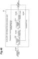
- Fig. 1 a system environment assumed by the present invention will be described using Fig. 1 .
- an audio signal acquired through a sensor such as a microphone is expressed in digital format and fed to an encoding unit 1.
- the encoding unit 1 encodes digital signals in a buffer every time a predetermined amount of audio signals consisting of a predetermined number of samples are saved in a built-in buffer.
- the foregoing predetermined amount i.e., the number of sample to be saved is called a frame length and an aggregate of digital signals saved in the buffer is called a frame.
- a frame length an aggregate of digital signals saved in the buffer.
- digital signals of 640 samples shall be saved in the buffer.
- the length of the buffer may be longer than one frame.
- encoding at the beginning is started only after digital signals of two frames have been saved in the buffer, whereby the digital signal of the next frame to the frame as an encoding target can be used for estimation of auxiliary information.
- the timing of execution of encoding may be determined so as to execute encoding in units of the frame length, or so as to execute encoding with an overlap of a certain length between frames.
- the encoding is performed using audio encoding such as 3GPP enhanced aacPlus and G.718. It should be noted that any method may be applicable as to the method of audio encoding.
- the auxiliary information is calculated using an audio or acoustic signal saved in the buffer for calculation of auxiliary information, and then is encoded and transmitted (auxiliary information code).
- the auxiliary information code may be transmitted in the same packet as an audio code, or may be transmitted in another packet different from a packet containing the audio code. The details of the operation of the encoding unit 1 will be described later.
- a packet configuration unit 2 adds information necessary for communication such as an RTP header to the audio code acquired by the encoding unit 1, to generate an audio packet.
- the audio packet thus generated is sent through a network to a receiver.
- a packet separation unit 3 separates the audio packet received through the network, into the packet header information and the other part (the audio code and auxiliary information code, which will be referred to hereinafter as "bitstream") and outputs the bitstream to a decoding unit 4.
- the decoding unit 4 performs decoding of the audio code contained in the audio packet received normally, and, if it detects an abnormality (a packet error or a packet loss) in the received audio packet, it performs packet loss concealment.
- the detailed operation of the decoding unit 4 will be described in the below embodiment.
- the decoded audio output from the decoding unit 4 is sent to a buffer of audio or the like to be reproduced through a speaker or the like, or stored in a recording medium such as a memory or a hard disk.
- the first embodiment will describe an example in which a parameter obtained by a functional approximation of powers of subframes shorter than one frame is used as auxiliary information about a temporal change of power.
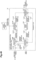
- the encoding unit 1 is provided with an audio encoding unit 11 to encode an audio signal, an auxiliary information encoding unit 12 to estimate and encode auxiliary information about a temporal change of power of the audio signal, which is used in packet loss concealment in decoding of the audio signal, and a code multiplexing unit 13 to multiplex an auxiliary information code obtained in encoding by the auxiliary information encoding unit 12 and an audio code obtained in encoding by the audio encoding unit 11, and output a bitstream of multiplex data.
- an audio encoding unit 11 to encode an audio signal
- an auxiliary information encoding unit 12 to estimate and encode auxiliary information about a temporal change of power of the audio signal, which is used in packet loss concealment in decoding of the audio signal
- a code multiplexing unit 13 to multiplex an auxiliary information code obtained in encoding by the auxiliary information encoding unit 12 and an audio code obtained in encoding by the audio encoding unit 11, and output a bitstream of multiplex data.
- the auxiliary information encoding unit 12 of these units is provided with a subframe power calculation unit 121, an attenuation coefficient estimation unit 122, and an attenuation coefficient quantization unit 123 which will be described later.
- the audio encoding unit 11 saves audio signal for a predetermined period of time and encodes a signal of an encoding target out of the saved input audio (step S1101 in Fig. 3 ).
- the encoding may be performed, for example, using the audio encoding such as 3GPP enhanced aacPlus defined in Literature " 3GPP TS26.401 'Enhanced aacPlus general audio codec General description '" and G.718 defined in Literature "Recommendation ITU-T G.718 'Frame error robust narrow-band and wideband embedded variable bit-rate coding of speech and audio from 8-32kbit/s"', or using any other encoding method.
- the subframe power calculation unit 121 in the auxiliary information encoding unit 12 saves the input audio for a predetermined period of time and later calculates a subframe power sequence for audio signals s(dT), s(1+dT), ..., s((d+1)T-1) out of the saved input audio.
- the calculation may occur later than encoding of target signals s(0), s(1), ..., s(T-1) by a predetermined number of frames (d frames in the present embodiment) (step S1211 in Fig. 3 ).
- the number of samples contained in one frame is defined as T herein.
- the letter k represents an index of a sample in each subframe (0 ⁇ k ⁇ K- 1). It is assumed herein that the number of samples in a digital signal in each subframe is K.
- the subframe power sequence may be calculated according to the following formula, where k l start represents an index of a start of the lth subframe and k l end represents an index of an end thereof.
- the attenuation coefficient estimation unit 122 acquires from the subframe power sequence a slope ⁇ opt of a straight line representing a temporal change of power for example, by the least square method or the like (step S1221 in Fig. 3 ). More simply, the slope may be calculated from P(0) and P(L-1). Here, the letter L represents the number of subframes contained in one frame. In addition to the slope ⁇ opt of the straight line, an intercept P opt may be calculated by a straight-line approximation of the subframe power sequence P(l).
- the power of subframe m is expressed herein by the following formula.
- P ⁇ m ⁇ opt ⁇ m + P opt
- the slope ⁇ opt and intercept P opt of the straight line are acquired in accordance with the following formulas (the least square method).
- the attenuation coefficient quantization unit 123 performs scalar quantization of the slope ⁇ opt of the straight line, then encodes the quantized data, and outputs the auxiliary information code (step S1231 in Fig. 3 ). It may use a scalar quantization codebook prepared in advance. In the case of the straight-line approximation of subframe powers P(l), the intercept P opt may also be encoded in addition to the slope ⁇ opt of the straight line.
- the code multiplexing unit 13 writes the audio code and the auxiliary information code in a predetermined order in a bitstream and outputs the bitstream (step S1301 in Fig. 3 ).
- the auxiliary information code of frame (N+1) is added to the audio code of frame N to obtain a bitstream, which is output from the code multiplexing unit 13.
- the packet configuration unit 2 adds the packet header information to the bitstream to obtain an audio packet to be transmitted as the N-th packet.
- steps S1101 to S1301 is repeated to an end of the input audio (step S1401).
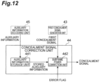
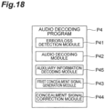
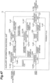
- the decoding unit 4 is provided with an error/loss detection unit 41, a code separation unit 40, an audio decoding unit 42, an auxiliary information decoding unit 45, a first concealment signal generation unit 43, and a concealment signal correction unit 44.
- the first concealment signal generation unit 43 of these units is provided with a decoding coefficient storage unit 431 and a stored decoding coefficient repetition unit 432.
- the concealment signal correction unit 44 is provided with an auxiliary information storage unit 441 and a subframe power correction unit 442.
- the error/loss detection unit 41 detects an abnormality (a packet error or a packet loss) in a received audio packet and outputs an error flag indicative of the result of the detection (step S4101 in Fig. 7 ).
- the error flag is set off to indicate the normality of packet by default and, when the error/loss detection unit 41 detects an abnormality in the received audio packet, it sets the error flag on (to indicate the packet abnormality).
- the error/loss detection unit 41 is provided with a counter that increases one for every reception of a new packet, and, when packets are assumed to be numbered in an order of transmission from the encoder, the error/loss detection unit 41 can compare a counter value with a number given to a packet to detect a packet loss if these values are different. It should be, however, noted that the packet loss detection method in the error/loss detection unit 41 described herein is just an example and the packet loss may be detected by any other method.
- the error/loss detection unit 41 sends the error flag to the audio decoding unit 42, the first concealment signal generation unit 43, the concealment signal correction unit 44, and the auxiliary information decoding unit 45 and sends the bitstream to the code separation unit 40.
- the code separation unit 40 receives the bitstream from the error/loss detection unit 41, separates the bitstream into the audio code and the auxiliary information code, and sends the audio code to the audio decoding unit 42 and the auxiliary information code to the auxiliary information decoding unit 45 (step S4001 in Fig. 7 ).
- the audio decoding unit 42 decodes the audio code to generate a decoded signal and outputs it as decoded audio.
- the decoding of audio code is performed using a decoding method corresponding to the aforementioned audio encoding unit 11.
- the audio decoding unit 42 also sends the decoded signal to the first concealment signal generation unit 43 (step S4311 in Fig. 7 ).
- the first concealment signal generation unit 43 stores the sent decoded signal into the decoding coefficient storage unit 431 shown in Fig. 11 .
- the stored decoded signal in storage therein is denoted by b(k, l).
- the stored signal may be at least d or more past frames.
- the letter k herein represents an index of a sample in a subframe (provided that 0 ⁇ k ⁇ K - 1) and the letter 1 an index of a subframe stored in the decoding coefficient storage unit 431 (provided that 0 ⁇ 1 ⁇ dL - 1).
- the auxiliary information decoding unit 45 decodes the auxiliary information code output from the code separation unit 40, to generate the auxiliary information, and then sends the auxiliary information to the concealment signal correction unit 44 (step S4202 in Fig. 7 ).
- the concealment signal correction unit 44 stores the auxiliary information into the auxiliary information storage unit 441 shown in Fig. 12 .
- the auxiliary information stored at this time is preferably that of several past frames (that of at least d frames or more).
- the auxiliary information decoding unit 45 decodes the auxiliary information code output from the code separation unit 40, to generate an index, and obtains a slope ⁇ J of a straight line corresponding to the index from a codebook.
- P(-1) represents a power of the last subframe in a signal received normally immediately before a frame loss.
- P ⁇ m ⁇ J ⁇ m + P ⁇ 1
- the subframe power is obtained by the following formula using the intercept P J .
- P ⁇ m ⁇ J ⁇ m + P J
- the error/loss detection unit 41 sends the error flag to the audio decoding unit 42, the first concealment signal generation unit 43, the concealment signal correction unit 44, and the auxiliary information decoding unit 45.
- the unit of repetition does not have to be limited to the last subframe but instead any part of b(k, l) may be extracted and repeated.
- Generation of the first concealment signal is not limited to the repetition as described above, and instead the first concealment signal may be calculated by extracting and repeating a waveform in a pitch unit from the decoding coefficient storage unit 431 or the first concealment signal may be generated by a prediction, for example, using the linear prediction. Alternatively, the first concealment signal may be generated in accordance with a model determined in advance, for example, as shown below.
- the subframe power correction unit 442 corrects the first concealment signal for a value of power of the first concealment signal in each of the subframes in accordance with the formula below to acquire a concealment signal y(K ⁇ l+k). Specifically, it performs the correction according to the below formula (provided that 0 ⁇ 1 ⁇ L-1 and 0 ⁇ k ⁇ K- 1).
- P -d (m) represents a power about a subframe contained in the auxiliary information code transmitted in the d-th packet before the packet (packet as a first concealment signal generation target) (step S4421 in Fig. 7 ).
- the subframe power correction unit 442 extracts the auxiliary information previously transmitted in the d-th packet, from the auxiliary information storage unit 441 (step S60 in Fig. 8 ), calculates a mean square amplitude value for each subframe as to the first concealment signal, and divides a value contained in each subframe, by the mean square amplitude value (step S61 in Fig. 8 ). This operation results in obtaining z'(K ⁇ l+k). Then it calculates a power of each subframe from the auxiliary information and multiplies the foregoing value of the subframe by a mean amplitude value obtained from the power (step S62 in Fig. 8 ). This multiplication results in obtaining the concealment signal y(K-l+k).
- steps S4101 to S4421 in Fig. 7 are repeated to the end of the input audio (step S4431 in Fig. 7 ).
- the first embodiment can use the parameter obtained by the functional approximation of powers of subframes shorter than one frame, as the auxiliary information about the temporal change of power.
- the auxiliary information may be auxiliary information obtained by encoding a subframe power sequence by vector quantization using preliminarily-learned or empirically-determined vectors c i (l).
- the second embodiment will describe an example of encoding or decoding, using as the auxiliary information, information about a vector obtained by vector quantization of powers of subframes, in the auxiliary information encoding unit 12 or in the auxiliary information decoding unit 45 in the first embodiment.
- the auxiliary information encoding unit 12 as shown in Fig. 9 , is provided with the subframe power calculation unit 121 and a subframe power vector quantization unit 124.
- the function and operation of the subframe power calculation unit 121 is the same as in the first embodiment.
- the subframe power vector quantization unit 124 performs vector quantization of powers P(l) of subframes l (provided that 0 ⁇ l ⁇ L - 1), encodes the result, and outputs the auxiliary information code.
- the letter I represents the number of entries of straight lines or vectors in a codebook and the letter J represents an index of a straight line or a vector selected.
- c i (l) represents the lth element of the ith code vector in the codebook.
- Selected J is encoded by binary encoding to obtain the auxiliary information code.
- the auxiliary information decoding unit 45 decodes the auxiliary information code output from the code separation unit 40, to generate the index J, obtains a vector c J (l) corresponding to the index J from the codebook, and outputs it.
- P ⁇ m c J l
- the second embodiment involves the encoding of the subframe power sequence by vector quantization using the preliminarily-learned or empirically-determined vectors, and uses the result as the auxiliary information.
- auxiliary information used a signal that is later by d or more frames than the signal encoded by the audio encoding unit 11, whereas the below third embodiment will describe an example in which a signal that is earlier by d frames than the signal encoded by the audio encoding unit 11 is used in the calculation of the auxiliary information.
- the subframe power calculation unit 121 saves input audio for a predetermined period of time and the subframe power sequence for audio signals s(-dT), s(1-dT), ..., s(-1) is calculated earlier by a predetermined number of frames (d frames in the present embodiment) than the encoding of target signals s(0), s(1), ..., s(T-1) out of the saved input audio. It is assumed herein that the number of samples contained in one frame is T.
- the letter k represents an index of a sample in a subframe (0 ⁇ k ⁇ K- 1). It is assumed herein that the number of samples of digital signals contained in each subframe is K.
- the subframe power correction unit 442 corrects the first concealment signal for a value of power of the first concealment signal in each subframe in accordance with the formula below to obtain the concealment signal y(K ⁇ l+k). Specifically, it performs the correction in accordance with the below formula (provided that 0 ⁇ 1 ⁇ L - 1 and 0 ⁇ k ⁇ K - 1).
- P d (m) represents the power about the subframe contained in the auxiliary information code transmitted in the d-th packet after the pertinent packet (packet of a first concealment signal generation target).
- the third embodiment allows use of the signal earlier by several frames than the signal encoded by the audio encoding unit for the calculation of the auxiliary information.
- the fourth embodiment will describe an example in which the processing as executed in the first and second embodiments is applied to signals resulting from time-frequency transform.
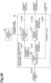
- the encoding unit 1 in the fourth embodiment has a configuration, as shown in Fig. 10 , in which a time-frequency transform unit 10 is added to the input side of the audio encoding unit 11 and the auxiliary information encoding unit 12, in comparison to the encoding unit 1 ( Fig. 2 ) in the first and second embodiments.
- the time-frequency transform unit 10 performs a time-frequency transform of an audio signal using an analysis QMF. Specifically, it performs the time-frequency transform by the following formula.
- the letter E represents the number of subframes in the time direction and the letter K represents the number of frequency bins.
- the letter k represents an index of a frequency bin (provided that 0 ⁇ k ⁇ K- 1) and the letter l represents an index of a subframe (provided that 0 ⁇ l ⁇ L - 1).
- the time-frequency transform can also be executed by MDCT (Modified Discrete Cosine Transform) or the like.
- the auxiliary information encoding unit 12 is provided with the subframe power calculation unit 121, attenuation coefficient estimation unit 122, and attenuation coefficient quantization unit 123. Since only the subframe power calculation unit 121 of these constituent elements is different from that in the first and second embodiments, the subframe power calculation unit 121 will be described below.
- the attenuation coefficient quantization unit 123 may employ the vector quantization as described in the second embodiment.
- the subframe power calculation unit 121 saves the audio signal for a predetermined period of time, and calculates the auxiliary information out of the saved audio signal as described below, using an audio signal V(k, l+d) obtained by transforming into the time-frequency domain an audio signal that is later by a predetermined number of frames (d frames) than the encoding of the target signal V(k, l).
- the power P(l+d) of subframe l+d is calculated by the following formula.
- the code multiplexing unit 13 writes the audio code and the auxiliary information code in a predetermined order, in the same manner as in the first and second embodiments, and outputs the resulting bitstream.
- the decoding unit 4 in the fourth embodiment has a configuration, as shown in Fig. 13 , in which an inverse transform unit 46 is added to the output side of the audio decoding unit 42 and the concealment signal correction unit 44, in comparison to the decoding unit 4 ( Fig. 6 ) in the first and second embodiments.
- the operations of the error/loss detection unit 41, code separation unit 40, and audio decoding unit 42 are the same as in the first and second embodiments, and thus the operations of the first concealment signal generation unit 43, auxiliary information decoding unit 45, concealment signal correction unit 44, and inverse transform unit 46 will be described below.
- the first concealment signal generation unit 43 is provided with the decoding coefficient storage unit 431 and the stored decoding coefficient repetition unit 432.
- the decoding coefficient storage unit 431 stores the decoded signal fed from the audio decoding unit 42.
- the stored decoded signal in storage is denoted by B(k, 1).
- the letter k herein represents an index of a sample in a subframe (provided that 0 ⁇ k ⁇ K- 1) and l represents an index of a subframe stored in the decoding coefficient storage unit 431 (provided that 0 ⁇ 1 ⁇ L - 1).
- the stored decoding coefficient repetition unit 432 obtains the first concealment signal z(k, l) using the stored decoded signal stored in the decoding coefficient storage unit 431. Specifically, it calculates the first concealment signal, for example, by repetition of the last subframe in accordance with the following formula.
- z k l B k , L ⁇ 1 (provided that 0 ⁇ l ⁇ L- 1 and 0 ⁇ k ⁇ K- 1)
- the unit of repetition does not have to be limited to the last subframe, and any part of B(k, l) may be extracted and repeated, or the first concealment signal may be generated, for example, by prediction using the linear prediction.
- the first concealment signal may be generated, for example, in accordance with a model determined in advance as described below.
- z k 0 ... , z k , L ⁇ 1 f B 0 0 , B 1 0 ... , B K ⁇ 1 , L ⁇ 1
- the auxiliary information decoding unit 45 decodes the auxiliary information code output by the code separation unit 40 to generate an index, obtains a slope ⁇ J of a straight line corresponding to the index from the codebook, and outputs it.
- P(-1) represents the power of the last subframe in the signal received normally immediately before the frame loss.
- P ⁇ m ⁇ J ⁇ m + P ⁇ 1
- the subframe powers are obtained by the following formula using the intercept P J .
- P ⁇ m ⁇ J ⁇ m + P J
- the auxiliary information decoding unit 45 in the present embodiment calculates the powers of the subframes using the codebook, as does the auxiliary information decoding unit 45 in the second embodiment.
- the concealment signal correction unit 44 is provided with the auxiliary information storage unit 441 and the subframe power correction unit 442.
- the auxiliary information storage unit 441 stores the auxiliary information fed from the auxiliary information decoding unit 45 when the error flag is off (to indicate packet normality).
- the auxiliary information to be stored is preferably that of several past frames.
- the subframe power correction unit 442 corrects the first concealment signal for a value of power of the first concealment signal in each subframe in accordance with the formula below to obtain the concealment signal Y(k, l). Specifically, it performs the correction in accordance with the below formula (provided that 0 ⁇ l ⁇ L- 1 and 0 ⁇ k ⁇ K- 1).
- P -d (m) represents the power about the subframe contained in the auxiliary information code transmitted in the d-th packet before the pertinent packet (packet of a first concealment signal generation target).
- the inverse transform unit 46 transforms the concealment signal or the decoded signal in the time-frequency domain into a signal in the time domain.
- the transform is performed by the following formula indicating a synthesis QMF.
- the letter l represents an index of a signal in the time domain, provided that 0 ⁇ l ⁇ K(2 + L).
- the fourth embodiment allows the processing procedures as executed in the first and second embodiments to be applied to the signals resulting from the time-frequency transform.
- the fifth embodiment will describe an example in which the technique described in the first embodiment is applied to each of subbands.
- the auxiliary information encoding unit 12 is provided with the subframe power calculation unit 121, attenuation coefficient estimation unit 122, and attenuation coefficient quantization unit 123.
- the letter k represents an index of a sample in a subframe (provided that 0 ⁇ k ⁇ K- 1).
- the subbands may be determined so that the widths of the subbands are unequal intervals, or they may be set to the width of the critical band, or the subband widths may be set to 1.
- the attenuation coefficient estimation unit 122 obtains a slope ⁇ i opt of a straight line indicative of a temporal change of power for each subframe from the subframe power sequence, for example, by the least square method or the like. More simply, the slope may be determined from P i (0) and P i (L-1). In addition to the slope ⁇ i opt of the straight line, an intercept P i opt obtained by a straight-line approximation of the subframe power sequence P i (l) may be obtained.
- the power of subframe m is represented herein by the following formula.
- the attenuation coefficient quantization unit 123 performs scalar quantization of slopes ⁇ i opt of straight lines, encodes the result, and outputs the auxiliary information code.
- the scalar quantization may be performed using a scalar quantization codebook prepared in advance.
- the intercept P i opt may be encoded in addition to the slope ⁇ i opt of the straight line.
- the vector quantization and subsequent encoding may be applied to a vector obtained by arranging ⁇ i opt of all the subbands, or the vector quantization and subsequent encoding may be applied to a vector obtained by arranging ⁇ i opt and P i opt .
- the stored decoding coefficient repetition unit 432 obtains the first concealment signal Z(k, l), using the stored decoded signal stored in the decoding coefficient storage unit 431.
- the stored decoded signal stored in the decoding coefficient storage unit 431 is denoted by B(k, l).
- the letter k herein represents an index of a sample in a subframe (0 ⁇ k ⁇ K- 1) and the letter l represents an index of a subframe stored in the decoding coefficient storage unit 431 (0 ⁇ l ⁇ L- 1).
- the stored decoding coefficient repetition unit 432 calculates the first concealment signal by repetition of the last subframe, as represented by the following formula.
- Z k l B k , dL ⁇ 1 (provided that 0 ⁇ l ⁇ L- 1 and 0 ⁇ k ⁇ K- 1)
- the unit of repetition does not have to be limited to the last subframe, and any part of B(k, l) may be extracted and repeated.
- the first concealment signal may be generated, for example, by a prediction using the linear prediction.
- the first concealment signal may be generated, for example, in accordance with a model determined in advance as described below.
- Z 0 0 , ... , Z K ⁇ 1 , L ⁇ 1 f b 0 0 , b 1 0 ... , b K ⁇ 1 , dL ⁇ 1
- the auxiliary information decoding unit 45 decodes the auxiliary information code output from the code separation unit 40, to generate indexes, and obtains a slope ⁇ i J of a straight line corresponding to each of the indexes from the codebook.
- P i (-1) represents the power of the last subframe in the signal received normally immediately before the packet loss.
- P ⁇ i m ⁇ J i ⁇ m + P i ⁇ 1
- the subframe powers are obtained by the following formula using the intercepts P i J .
- P ⁇ i m ⁇ J i ⁇ m + P J i
- the auxiliary information storage unit 441 included in the concealment signal correction unit 44 stores the auxiliary information fed from the auxiliary information decoding unit 45 when the error flag indicates the value indicative of the normal packet.
- the auxiliary information to be stored is preferably that of several past frames (at least d frames or more).
- the subframe power correction unit 442 corrects the first concealment signal for a value of power of the first concealment signal in each subframe in accordance with the formula below to obtain the concealment signal Y(k, l). Specifically, it performs the correction according to the below formula (provided that 0 ⁇ l ⁇ L- 1 and 0 ⁇ k ⁇ K- 1).
- P i -d (m) represents the power of the ith subband about the subframe contained in the auxiliary information code transmitted in the d-th packet before the pertinent packet (packet of a first concealment signal generation target).
- the fifth embodiment allows the technique described in the first embodiment to be applied to each of a plurality of subbands.
- the sixth embodiment will describe an example in which the auxiliary information encoding unit obtains two or more pieces of auxiliary information, encodes them separately, and puts the encoded data into a bitstream.
- the differences from the first embodiment will be mainly described below.
- the encoding unit 1 in the sixth embodiment is provided with the audio encoding unit 11, auxiliary information encoding unit 12, and code multiplexing unit 13.
- the audio encoding unit 11 is the same as in the first embodiment.
- the auxiliary information encoding unit 12, as shown in Fig. 4 is provided with the subframe power calculation unit 121, attenuation coefficient estimation unit 122, and attenuation coefficient quantization unit 123.
- the subframe power calculation unit 121 saves the input audio for a predetermined period of time, and calculates a subframe power sequence P 1 (l) for audio signals s(dT), s(1+dT), ..., s((d+1)T-1) that are later by a predetermined number of frames (d frames in the present embodiment) than the encoding of the target signals s(0), s(1), ..., s(T-1) out of the saved input audio.
- the subframe power calculation unit 121 calculates a subframe power sequence P 2 (l) for audio signals s((d+1)T), s(1+(d+1)T), ..., s((d+2)T-1) later by a predetermined number of frames ((d+1) frames in the present embodiment).
- the present embodiment defines K as the length of each subframe, but different lengths may be used for the respective subframes, which are determined in advance for the respective subframes.
- the subframe power sequence may also be calculated in accordance with the following formula where k l start represents an index of a start of the lth subframe and k l end represents an index of an end thereof.
- the attenuation coefficient estimation unit 122 calculates slopes ⁇ 1 opt , ⁇ 2 opt of straight lines indicative of respective temporal changes of power from the subframe power sequences P 1 (l), P 2 (l), for example, by the least square method or the like.
- the calculation method is the same as that performed by the attenuation coefficient estimation unit 122 in the first embodiment.
- the attenuation coefficient quantization unit 123 performs the scalar quantization of each of the slopes ⁇ 1 opt , ⁇ 2 opt of the straight lines, encodes the results of the scalar quantization, and outputs auxiliary information codes C 1 , C 2 . It may use the scalar quantization codebook prepared in advance. In the case of the straight-line approximation of subframe power P(l), intercepts P 1 opt , P 2 opt may also be encoded in addition to the slopes ⁇ 1 opt , ⁇ 2 opt of the straight lines.
- the code multiplexing unit 13 writes the audio code and the auxiliary information codes C 1 , C 2 in a predetermined order and outputs a bitstream.
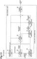
- Fig. 14 shows an example of temporal relationship between signals as audio encoding targets and signals as auxiliary information encoding targets, and a configuration of bitstreams.
- the auxiliary information code of frame (N+1) and the auxiliary information code of frame (N+2) are added to the audio code of frame N to obtain a bitstream, which is output from the code multiplexing unit 13.
- the packet configuration unit 2 in Fig. 1 adds the packet header information to the bitstream to obtain an audio packet to be transmitted as the N-th packet.
- the auxiliary information to be generated may be three or more pieces of auxiliary information.
- the auxiliary information may be calculated for a target of an audio signal that is earlier by one or more frames than the audio signal encoded by the audio encoding unit.
- the decoding unit 4 in the sixth embodiment is provided with the error/loss detection unit 41, code separation unit 40, audio decoding unit 42, auxiliary information decoding unit 45, first concealment signal generation unit 43, and concealment signal correction unit 44. Since the operations of the error/loss detection unit 41, audio decoding unit 42, and first concealment signal generation unit 43 are the same as those in the first embodiment, redundant description is omitted herein.
- the code separation unit 40 reads the audio code and auxiliary information codes C 1 , C 2 from the bitstream, and sends the audio code to the audio decoding unit 42 and the auxiliary information codes C 1 , C 2 to the auxiliary information decoding unit 45.
- the auxiliary information decoding unit 45 decodes the auxiliary information codes C 1 , C 2 , calculates the auxiliary information, and sends the result to the concealment signal correction unit 44.
- the auxiliary information decoding unit 45 decodes the auxiliary information codes C 1 , C 2 output from the code separation unit 40, to generate indexes, and obtains slopes ⁇ J of straight lines corresponding to the respective indexes from the codebook.
- P(-1) represents the power of the last subframe in the signal received normally immediately before the frame loss.
- the concealment signal correction unit 44 is provided with the auxiliary information storage unit 441 and the subframe power correction unit 442.
- the auxiliary information storage unit 441 stores the auxiliary information fed from the auxiliary information decoding unit 45 when the error flag indicates the value indicative of the normal packet.
- the auxiliary information to be stored is preferably that of several past frames (at least d frames or more). In the present embodiment, the auxiliary information of two frames is acquired per packet.
- the subframe power correction unit 442 corrects the first concealment signal for a value of power of the first concealment signal in each subframe in accordance with the formula below to obtain the concealment signal Y(K ⁇ l+k). Specifically, it performs the correction according to the below formula (provided that 0 ⁇ l ⁇ L- 1 and 0 ⁇ k ⁇ K- 1).
- P -d (m) represents the power about the subframe contained in the auxiliary information code C 1 transmitted in the d-th packet before the pertinent packet (packet of a first concealment signal generation target).
- the subframe power correction unit 442 extracts the auxiliary information transmitted in the d-th packet, from the auxiliary information storage unit 441 (step S60 in Fig. 8 ), calculates the mean square amplitude value for each subframe as to the first concealment signal, and divides the value contained in the subframe, by the mean square amplitude value (step S61). This calculation results in obtaining z'(K ⁇ l+k). Then powers of respective subframes are calculated from the auxiliary information and the value of the subframe is multiplied by a mean amplitude value obtained from the powers (step S62). This multiplication results in obtaining the concealment signal Y(K ⁇ l+k).
- the above processing of steps S4101 to S4421 ( Fig. 7 ) is repeated to the end of the input audio (step S4431).
- the packet loss can also be concealed in the case of occurrence of the consecutive packet loss by carrying out the same processing, using the power about the subframe contained in the auxiliary information code C 2 transmitted in the d-th packet before the pertinent packet (packet of a first concealment signal generation target).
- the sixth embodiment allows the auxiliary information encoding unit to obtain two or more pieces of auxiliary information, encode them separately, and put them into the bitstream.
- Fig. 19 shows a configuration diagram of a modification example of the decoding unit 4.
- the decoding unit 4 in Fig. 13 in the fourth embodiment described above was configured to feed the error flag to the audio decoding unit 42, the first concealment signal generation unit 43, the concealment signal correction unit 44, and the auxiliary information decoding unit 45, whereas the configuration in Fig. 19 omits these inputs. Even in the configuration with omission of these inputs, there is no input to the audio decoding unit 42 and the auxiliary information decoding unit 45 with the error flag being on and therefore the error flag can be determined to be on by the absence of the input.
- the state of the error flag can be determined, depending upon the presence/absence of the input to the audio decoding unit 42 and the auxiliary information decoding unit 45.
- the first concealment signal generation unit 43 and the concealment signal correction unit 44 can also determine the state of the error flag in the same manner.
- the decoding unit 4 in Fig. 13 is configured so that an audio parameter storage unit 47 shown in Fig. 19 is included in the first concealment signal generation unit 43, but the audio parameter storage unit 47 may be configured as a constituent element independent of the first concealment signal generation unit 43, as shown in Fig. 19 .
- the function of the decoding unit 4 of the configuration in Fig. 19 is substantially the same as that of the decoding unit 4 in Fig. 13 .
- the decoding unit 4 in the first, second, third, fifth, and sixth embodiments shown in Fig. 6 may also be configured so that the input of the error flag to the audio decoding unit 42, the first concealment signal generation unit 43, the concealment signal correction unit 44, and the auxiliary information decoding unit 45 is omitted and/or so that the audio parameter storage unit is a constituent element independent of the first concealment signal generation unit 43, as described above.
- the overall configuration of the encoding unit 1 is also as shown in Fig. 2 and the overall configuration of the decoding unit 4 is as shown in Fig. 6 .
- the description about the overall configuration is omitted as in the second to sixth embodiments.
- the auxiliary information encoding unit 12 will be described below in detail as a characteristic portion of the encoding unit 1 in the seventh embodiment.
- the auxiliary information encoding unit 12, as shown in Fig. 20 is provided with a transient detection unit 124A, a transient position quantization unit 125, a transient power scalar quantization unit 126, and a parameter encoding unit 127.
- the transient detection unit 124A saves the input audio for a predetermined period of time, and detects a transient using audio signals s(dT), s(1+dT), ..., s((d+1)T-1) that is later by a predetermined number of frames (d frames in the present embodiment) than the encoding of the target signals s(0), s(1), ..., s(T-1) out of the saved input audio (step S7401 in Fig. 21 ).
- the auxiliary information encoding target frame may be a frame that is later by one or more frames than an audio encoding target frame or may be a frame that is earlier by one or more frames than an audio encoding target frame.
- the auxiliary information codes may be calculated from two or more frames selected from frames that are earlier or later by one or more frames than the audio encoding target frame.
- a method for detection of the transient can be, for example, the method described in Section 7.1 in "ITU-T Recommendation G.719.”
- the transient may also be detected using one of other standard technologies and non-standard technologies.
- the power is calculated in each subframe and then a temporal change of each subframe is compared with a threshold to determine whether or not there is a transient.
- Calculated as a result of the transient detection are: a transient flag F tran indicative of whether a transient is contained in the auxiliary information encoding target frame, a position l tran of the transient, and a subframe power sequence P(l).
- the transient detection unit 124A When a power of a subframe at the position l tran of the transient is represented by P(l tran ) as shown in Fig. 41 , the transient detection unit 124A outputs the position I tran of the transient through line 1L45, outputs the power P(l tran ) of the subframe at the position l tran of the transient through line 1L46, and outputs the transient flag F tran through line 1L47.
- the transient detection unit 124A may be configured to output the position l tran of the transient and the subframe power sequence P(l) through line 1L46.
- the transient detection unit 124A is supposed to calculate the same parameter as the subframe power sequence calculated by the subframe power calculation unit 121 in Fig. 4 .
- the transient detection unit 124A also calculates and outputs the same parameter as the subframe power sequence calculated by the subframe power calculation unit 121 in Fig. 4 .
- the parameter encoding unit 127 encodes only the transient flag and outputs the encoded data as an auxiliary information code (step S7702 in Fig. 21 ).
- the transient position quantization unit 125 performs the scalar quantization of the position l tran of the transient by a predetermined bit count and outputs quantized position information (step S7501 in Fig. 21 ).
- the scalar quantization may be performed by a method of binary coding with l tran being regarded as a binary number, or by a method of providing predetermined positions with indexes, and performing binary encoding of an index at the closest position to l tran , or by entropy coding such as Huffman coding, or by any other quantization method.
- Fig. 42(a) shows a schematic diagram of an example of transient position information encoding by the binary coding
- Fig. 42(b) a schematic diagram of an example of transient position information encoding by the scalar quantization.
- another available method is as follows: two or more subframe indexes are selected as "information indicative of a change of power," in addition to the position of the transient, and the two or more subframe indexes thus selected are encoded and transmitted. There are no particular restrictions on the method of encoding herein.
- the transient power scalar quantization unit 126 When the value for inclusion of a transient in a frame is set in the transient flag F tran , the transient power scalar quantization unit 126 performs the scalar quantization of the power of the subframe corresponding to the position l tran of the transient and outputs the quantized transient power (step S7601 in Fig. 21 ).
- the quantization is carried out according to the below formula.
- C can be the value of 1.55 and ⁇ can be the value of 0.001 or the like, but these constants may be changed according to the quantization bit count or the like.
- the power of the transient is quantized into an index ranging from 0 to 63.
- the quantization may be carried out using a codebook determined in advance by learning or the like, or any other quantization means may be applied.
- the transient flag F tran does not indicate the value for inclusion of a transient in a frame, the value indicative of a normal frame is entered in I E in the above formula.
- the parameter encoding unit 127 combines the transient flag, the quantized position information, and the quantized transient power together and outputs the auxiliary information code (step S7701 in Fig. 21 ). It is also possible to adopt a method in which the transient flag, the quantized position information, and the quantized transient power are regarded together as a vector and then the vector is encoded by vector quantization or by any other encoding method. There are no particular restrictions on the method of encoding.
- the overall configuration of the decoding unit 4 is as shown in Fig. 6 described in the first embodiment.
- the following will describe the configurations and operations of the auxiliary information decoding unit 45 and the concealment signal correction unit 44 which are characteristic configurations in the seventh embodiment.
- the first concealment signal generation unit 43 may generate the first concealment signal by an existing standard technique, for example, as described in Section 5.2 in TS26.402, in addition to the techniques described in the first to sixth embodiments, or may generate the first concealment signal by another concealment signal generation technique which is not a standard.
- the auxiliary information decoding unit 45 is provided with a transient flag decoding unit 129, a transient position decoding unit 1212, and a transient power decoding unit 1213.
- the operation of the auxiliary information decoding unit 45 of this configuration will be described based on Fig. 23 .
- the auxiliary information decoding unit 45 decodes the auxiliary information code and determines whether the obtained transient flag F tran is on (indicative of a frame including a transient) or off (indicative of a frame including no transient) (step S7901 in Fig. 23 ).
- transient flag F tran indicates a frame containing no transient
- only the value of the transient flag F tran is output as auxiliary information (step S7142 in Fig. 23 ).
- the auxiliary information decoding unit 45 outputs the calculated transient flag F tran , quantized position information, and decoded transient power as auxiliary information (step S7141 in Fig. 23 ).
- the concealment signal correction unit 44 will be described. As shown in Fig. 24 , the concealment signal correction unit 44 is provided with the auxiliary information storage unit 441 and the subframe power correction unit 442.
- the first to sixth embodiments showed the configuration in which the error flag was fed to the subframe power correction unit 442, whereas the concealment signal correction unit 44 in Fig. 24 is configured not to feed the error flag to the subframe power correction unit 442 and is further configured to determine the state of the error flag by the presence/absence of input of the first concealment signal from the first concealment signal generation unit 43.
- the error flag is determined to be off, with input of the first concealment signal from the first concealment signal generation unit 43; the error flag is determined to be on, without input of the first concealment signal from the first concealment signal generation unit 43.
- the concealment signal correction unit may be configured to perform the determination on the error flag by supplying the error flag to the auxiliary information storage unit 441 and the subframe power correction unit 442.
- the operation of the concealment signal correction unit 44 is as shown in the flowchart of Fig. 25 .
- the state of the error flag is determined by the presence/absence of input of the first concealment signal from the first concealment signal generation unit 43 as described above (step S7800 in Fig. 25 ).
- the auxiliary information decoding unit 45 decodes the auxiliary information code and outputs the transient flag, the transient position information, and the decoded transient power through line 6L001 in Fig. 24 (step S7101 in Fig. 25 ).
- the auxiliary information storage unit 441 stores the transient flag, the transient position information, and the decoded transient power (step S7111 in Fig. 25 ).
- the subframe power correction unit 442 reads the transient flag, quantized position information, and decoded transient power from the auxiliary information storage unit 441, and corrects the first concealment signal for a value of power of the first concealment signal z(K ⁇ l+k) in each subframe to obtain a concealment signal y(K ⁇ l+k) (provided that 0 ⁇ 1 ⁇ L- 1 and 0 ⁇ k ⁇ K- 1) (step S7901 in Fig. 25 ). Specifically, the subframe power correction unit 442 corrects the value of the power of the first concealment signal z(K ⁇ l+k) in accordance with the following procedure.
- the subframe power correction unit calculates a difference between the power of the first concealment signal at the position of the transient and the decoded transient power (differential transient power).
- P ⁇ tran P l tran ⁇ P ⁇ tran
- the subframe power correction unit corrects the power of the first concealment signal corresponding to each subframe after the position of the transient, using the foregoing differential transient power, to obtain a corrected concealment signal subframe power.
- P ⁇ m P m 0 ⁇ m ⁇ l tran P m + P ⁇ tran l tran ⁇ m ⁇ L ⁇ 1
- the subframe power correction unit 442 normalizes each of the resulting powers (step S7801 in Fig. 25 ).
- the lengths of the respective subframes may be set to be unequal as in the second to sixth embodiments. The present embodiment will detail the case where the lengths of the respective subframes are equal.
- the subframe power correction unit multiplies the normalized first concealment signal by the corrected concealment signal subframe power to calculate a concealment signal (step S7131 in Fig. 25 ).
- a corrected concealment signal power is calculated using a predetermined prediction coefficient a p .
- the prediction coefficient may be switched to another, depending upon properties of subframe power sequences.
- smoothing may be carried out using a model determined in advance.
- P ⁇ m f P ′ 0 , ⁇ , P ′ L ⁇ 1
- the function f to be used herein may be, for example, a sigmoid function, a spline function, or the like and there are no particular restrictions thereon as long as smoothing can be implemented.
- the seventh embodiment as described above can realize the high-accuracy packet loss concealment for the transient signal, using the indication information indicative of the presence/absence of a sudden change of power, the position of the transient in the frame as an auxiliary information encoding target, and the power of the subframe at the position of the transient, as the auxiliary information about the sudden change of power (transient).
- the auxiliary information encoding unit 12 in the eighth embodiment is provided with the transient detection unit 124A, the transient position quantization unit 125, the transient power scalar quantization unit 126, a transient power vector quantization unit 128, and the parameter encoding unit 127.
- the eighth embodiment is different in the provision of the transient power vector quantization unit 128, in addition to the transient power scalar quantization unit 126 in the seventh embodiment, and in the configuration and operation of the auxiliary information decoding unit 45, from the seventh embodiment.
- the transient detection unit 124A detects a transient in an auxiliary information encoding target frame (step S7401 in Fig. 27 ).
- a detection method of the transient is the same as in step S7401 in Fig. 21 in the seventh embodiment.
- the auxiliary information encoding target frame may be a frame later by one or more frames than the audio encoding target frame or a frame earlier by one or more frames than it. Furthermore, two or more frames may be selected from frames earlier or later by one or more frames than the audio encoding target frame, and the auxiliary information codes are calculated therefrom and used herein.
- the transient position quantization unit 125 quantizes the transient position information (step S7501 in Fig. 27 ).
- a method of the quantization is the same as in step S7501 in Fig. 21 in the seventh embodiment.
- the transient power vector quantization unit 128 normalizes the subframe power sequence, using the power of the subframe indicated by the quantized position information, and then performs vector quantization (step S8701 in Fig. 27 ).
- P ⁇ m P m P l tran
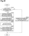
- the present embodiment showed the example of the vector quantization after the normalization of the subframe power sequence, whereas a modification example may adopt a configuration to perform the vector quantization without execution of the normalization as shown in Fig. 28 .
- the operation of the auxiliary information encoding unit 12 in Fig. 28 is as shown in Fig. 29 , and the vector quantization is carried out according to the following formula (step S8901 in Fig. 29 ), instead of S8701 in Fig. 27 .
- the other is the same as in Fig. 27 .
- the eighth embodiment is different from the seventh embodiment, in the configuration and operation of the auxiliary information decoding unit 45 in Fig. 30 and in the operations of the auxiliary information storage unit 441 and the subframe power correction unit 442 in the concealment signal correction unit 44.
- the auxiliary information decoding unit 45 is provided with the transient flag decoding unit 129, the transient position decoding unit 1212, the transient power decoding unit 1213, and a transient power vector decoding unit 1214.
- the operation of the auxiliary information decoding unit 45 is shown in Fig. 31 .
- the auxiliary information decoding unit 45 reads the transient flag F tran , the quantized position information l tran , the quantized transient power I E , and the code vector index J from the auxiliary information code and determines the state of the transient flag F tran (step S901 in Fig. 31 ).
- the value of the transient flag F tran indicates no transient, only the value of the transient flag F tran is output as auxiliary information (step S906 in Fig. 31 ), as in the seventh embodiment.
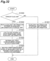
- the auxiliary information storage unit 441 stores the transient flag, decoded position information, decoded transient power, and code vector (step S1501 in Fig. 32 ).
- the subframe power correction unit 442 corrects the first concealment signal z(K ⁇ l+k) for a value of power of the first concealment signal in each subframe in accordance with the below-described formula to obtain the concealment signal y(K ⁇ l+k) (provided that 0 ⁇ 1 ⁇ L- 1 and 0 ⁇ k ⁇ K- 1). Specifically, the value of power of the first concealment signal is corrected in each subframe in accordance with the following procedure.
- the correction unit reads the transient flag, decoded position information, decoded transient power, and code vector from the auxiliary information storage unit (step S1502 in Fig. 32 ).
- the power of each subframe is calculated using the auxiliary information (step S1503 in Fig. 32 ).
- the subframe power is calculated.
- the correction unit calculates the differential transient power which is the difference between the subframe power corresponding to the transient position and the decoded transient power.
- P ⁇ tran P l tran ⁇ P tran
- the corrected concealment signal subframe power is calculated using the differential transient power and the code vector.
- P ⁇ m P tran ⁇ c J L ⁇ l tran ⁇ 1 + m 0 ⁇ m ⁇ l tran P m + P ⁇ tran l tran ⁇ m ⁇ L ⁇ 1
- the present embodiment shows the example of the vector quantization after the normalization of the values of the subframe power sequence on the encoder side, but it is also possible to adopt a method in which the vector quantization of the subframe power sequence is carried out without execution of the normalization.
- the corrected concealment signal subframe power is calculated as follows.
- the first concealment signal is normalized in each subframe (step S1504 in Fig. 32 ).
- the normalized first concealment signal is multiplied by the corrected subframe power and the concealment signal is output (step S1505 in Fig. 32 ).
- y K ⁇ l + k 10 P ⁇ m / 20 ⁇ z ′ K ⁇ l + k
- the eighth embodiment as described above can realize the high-accuracy packet loss concealment for the transient signal, further using the information obtained by the vector quantization of the transient power change, as the auxiliary information about the sudden change of power (transient).
- the ninth embodiment will describe an example in which the processing as executed in the seventh and eighth embodiments is applied to signals resulting from a time-frequency transform.
- the auxiliary information encoding target frame may be a frame later by one or more frames than the audio encoding target frame or a frame earlier by one or more frames than it.
- the auxiliary information codes may be calculated from two or more frames selected from frames that are earlier or later by one or more frames than the audio encoding target frame, and used herein.
- the encoding unit 1 in the ninth embodiment has the same configuration as in Fig. 2 described in the first embodiment, and thus the detailed description of the entire unit will be omitted herein.
- the time-frequency transform is as described in the fourth embodiment and the signals after the transform into the frequency domain are denoted by V(k, l).
- the letter k herein is an index of a frequency bin (provided that 0 ⁇ k ⁇ K - 1) and l an index of a subframe (provided that 0 ⁇ 1 ⁇ L - 1).
- the auxiliary information encoding unit will be described below in detail as a characteristic portion of the ninth embodiment.
- the auxiliary information encoding unit as shown in Fig. 20 , is provided with the transient detection unit 124A, transient position quantization unit 125, transient power scalar quantization unit 126, and parameter encoding unit 127.
- the ninth embodiment will describe an example using a position of a transient in a frame as an auxiliary information encoding target, and a power of at least one subband out of subbands resulting from division of the entire band into the subbands, out of powers in a subframe at the position of the transient, as auxiliary information about a sudden change of power (transient).
- the auxiliary information may be encoded by the vector quantization as executed in the eighth embodiment.
- the number of subbands to be encoded is not limited to one, but the same processing may be carried out for two or more subbands.
- the transient detection unit 124A detects a transient, using the signals obtained by the transform into the frequency domain.
- the detection of transient may be carried out using the means used in the seventh embodiment, or using TS26.404 or the like which is the standard technology of transient detection for signals in the frequency domain, or using another transient detection technology for frequency-domain signals.
- the subband power sequence is calculated herein about values in a range (K s ⁇ k ⁇ K e ) in the frequency domain preliminarily determined in the transient detection.
- the signals in the frequency band to be used in the detection of transient may be signals in the entire band or only at least one specific subband may be used.
- the subband power sequence to be encoded as auxiliary information may be calculated using the entire band or using only at least one specific subband.
- the subband power sequence to be encoded as auxiliary information may be a subband power sequence calculated for subbands used in the transient detection, or a subband power sequence calculated for subbands not used in the transient detection.
- the auxiliary information decoding unit 45 reads the transient flag F tran , quantized position information l tran , and quantized transient power I E from the auxiliary information code.
- the auxiliary information decoding unit 45 decodes the auxiliary information code by corresponding decoding means to obtain these parameters. For example, in the case using the linear quantization as described above, the decoded transient power is obtained from the quantized transient power in accordance with the following formula.
- P ⁇ tran 10 C ⁇ I E / 20
- the transient flag from the auxiliary information storage unit and determines the state of the transient.
- a power is obtained in each subframe as to the first concealment signal.
- the lengths of the respective subframes may be set to be unequal as in the second to sixth embodiments. The present embodiment will detail the case where the lengths of the respective subframes are equal.
- the smoothing as described in the seventh embodiment may be applied or the vector quantization as described in the eighth embodiment may be combined.
- the concealment signal obtained finally is transformed into a signal in the time domain by the inverse transform unit 46 and the resulting concealment signal is output.
- the auxiliary information encoding unit 12 is provided with the attenuation coefficient estimation unit 122, attenuation coefficient quantization unit 123, transient detection unit 124A, transient position quantization unit 125, transient power scalar quantization unit 126, and parameter encoding unit 127.
- the operations of the individual constituent elements are the same as those described in the first, second, seventh, and eighth embodiments.
- the overall operation of the auxiliary information encoding unit 12 will be described below.
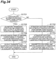
- the operation of the auxiliary information encoding unit 12 is shown in the flowchart of Fig. 34 .
- the transient detection unit 124A determines whether there is a transient in the input signal.
- the operation of the transient detection unit 124A is the same as in the seventh embodiment (step S1701 in Fig. 34 ).
- the attenuation coefficient estimation unit 122 estimates the attenuation coefficient from the subframe power sequence by the same operation as in the first embodiment (step S1702 in Fig. 34 ).
- the attenuation coefficient quantization unit 123 quantizes the attenuation coefficient by the same operation as in the first embodiment, and outputs the quantized attenuation coefficient (step S1703 in Fig. 34 ).
- the parameter encoding unit 127 outputs the quantized attenuation coefficient as an auxiliary information code (step S1704 in Fig. 34 ).
- transient position quantization unit 125 and the transient power scalar quantization unit 126 with the signal as an auxiliary information encoding target containing a transient are the same as in the seventh embodiment (steps S1705-S1706 in Fig. 34 ).
- the parameter encoding unit 127 encodes the transient flag, transient position information, and quantized transient power and outputs the auxiliary information code (step S1707 in Fig. 34 ).
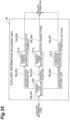
- the overall configuration of the tenth embodiment is also the same as in the first embodiment to the ninth embodiment and therefore the operations of the auxiliary information decoding unit 45 and the concealment signal correction unit 44 being the major differences will be described below.
- the auxiliary information decoding unit 45 as shown in Fig. 35 , is provided with the transient flag decoding unit 129, attenuation coefficient decoding unit 1210, transient position decoding unit 1212, and transient power decoding unit 1213.
- the operation of the auxiliary information decoding unit 45 will be described below.
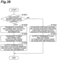
- the flowchart to show the flow of operation is as shown in Fig. 36 .
- the transient flag decoding unit 129 reads the transient flag from the auxiliary information code and determines whether the auxiliary information code corresponds to a transient signal (step S1901 in Fig. 36 ).
- the attenuation coefficient decoding unit 1210 reads the quantized attenuation coefficient code from the auxiliary information code, decodes the quantized attenuation coefficient code, and outputs the resulting decoded attenuation coefficient and transient flag as auxiliary information (steps S1902-S1903 in Fig. 36 ).
- the basic operation of the attenuation coefficient decoding unit 1210 is the same as the calculation of the attenuation coefficient in the auxiliary information decoding unit in the first embodiment.
- the transient position decoding unit 1212 decodes the quantized transient position information and outputs the resulting transient position information (which will be referred to hereinafter as "decoded position information") (step S1904 in Fig. 36 ), and the transient power decoding unit 1213 decodes the encoded quantized power and outputs the resulting decoded transient power (step S1905 in Fig. 36 ), thereby outputting the transient flag, the decoded position information, and the decoded transient power as auxiliary information (step S1906 in Fig. 36 ).
- the operations of the transient position decoding unit 1212 and the transient power decoding unit 1213 are the same as in the seventh embodiment.
- the subframe power correction unit 442 normalizes the first concealment signal (step S2005 in Fig. 37 ).
- the method of normalization is the same as the normalization of the first concealment signal in the seventh embodiment.
- the subframe power correction unit 442 reads the transient flag from the auxiliary information storage unit 441 and determines the value of the transient flag (step S2006 in Fig. 37 ).
- the subframe power correction unit 442 reads the decoded position information and decoded transient power from the auxiliary information storage unit 441, calculates powers of respective subframes from these decoded position information and decoded transient power, and multiplies the value of the subframe obtained in step S2005, by a mean amplitude value calculated from the foregoing powers, to obtain the concealment signal (step S2007 in Fig. 37 ).
- the technique of the tenth embodiment described above may be applied to the input signal resulting from the transform into the frequency domain.
- the calculation and encoding of auxiliary information may be carried out for at least one subband.
- the encoder side can output the auxiliary information code by the means in the seventh or eighth embodiment with the input signal being a transient signal, and conceal a packet loss signal with higher quality with the use of the means in the first to third embodiments for the part other than the transient signal as well.
- a code length selection unit 128A is added to the auxiliary information encoding unit 12, whereby the auxiliary information is encoded by a value of 2 or more bits only if the value of the transient flag is the value indicating the existence of a transient and whereby the auxiliary information is encoded by only one bit indicative of the transient flag if the value of the transient flag is the value indicative of the absence of a transient.
- the auxiliary information may be encoded by the variable length coding as described above, or may be always encoded by the same bit count so as to fill zeros as many as the same bit count as the transient position information and the quantized transient power in the absence of a transient as well, or any other information may be encoded instead to form the auxiliary information code.
- the auxiliary information encoding unit 12 is provided with the transient detection unit 124A, transient position quantization unit 125, transient power scalar quantization unit 126, parameter encoding unit 127, and code length selection unit 128A.
- the operation of the auxiliary information encoding unit 12 will be described based on Fig. 39 .
- the transient detection unit 124A performs the detection of transient by the same operation as in the seventh embodiment (step S2201 in Fig. 39 ).
- the code length selection unit 128A When the transient flag F tran indicates the value for inclusion of a transient in a frame, the code length selection unit 128A outputs a predetermined bit count larger than one bit (step S2204 in Fig. 39 ).
- the transient position quantization unit 125 scalar-quantizes the position l tran of the transient by the predetermined bit count and outputs the quantized position information (step S2205 in Fig. 39 ).
- the operation of the transient position quantization unit 125 is the same as in the seventh embodiment.
- the transient power scalar quantization unit 126 performs the scalar quantization of the power of the subframe corresponding to the position l tran of the transient and outputs the quantized transient power (step S2206 in Fig. 39 ).
- the operation of the transient power scalar quantization unit 126 is the same as in the seventh embodiment.
- the parameter encoding unit 127 outputs the transient flag, quantized position information, and quantized transient power together as an auxiliary information code (step S2207 in Fig. 39 ). At this time, the total length of the auxiliary information code is the value determined in step S2204 in Fig. 39 .
- step S2201 when it is determined in step S2201 that the transient flag F tran does not show the value for inclusion of a transient in a frame, the code length selection unit 128A determines the code length to be one bit (step S2202 in Fig. 39 ). Next, the parameter encoding unit 127 encodes only the transient flag by one bit and outputs it (step S2203 in Fig. 39 ).
- the auxiliary information decoding unit 45 is provided with the transient flag decoding unit 129, transient position decoding unit 1212, and transient power decoding unit 1213, as in the seventh embodiment.
- the operation of the auxiliary information decoding unit 45 of this configuration will be described based on Fig. 40 .
- the auxiliary information decoding unit 45 decodes the auxiliary information code and determines whether the resulting transient flag F tran is on (to indicate a frame containing a transient) or off (to indicate a frame containing no transient) (step S2401 in Fig. 40 ).
- the transient flag decoding unit 129 When the transient flag F tran shows a frame containing a transient, the transient flag decoding unit 129 further reads the quantized position information from the auxiliary information code and outputs the information to the transient position decoding unit 1212, and it further reads the quantized transient power I E from the auxiliary information code and outputs the power to the transient power decoding unit 1213 (step S2402 in Fig. 40 ).
- the transient position decoding unit 1212 decodes the quantized position information and outputs the resulting decoded position information l tran (step S2403 in Fig. 40 ). Furthermore, the transient power decoding unit 1213 decodes the quantized transient power I E and outputs the resulting decoded transient power P(l tran ) (step S2404 in Fig. 40 ).
- the eleventh embodiment as described above allows the code length of the auxiliary information to be made variable.
- the configuration of the encoding unit 1 is the same as in the first embodiment.
- the below will describe the configuration and operation of the auxiliary information encoding unit 12 which is a characteristic configuration in the present embodiment.
- the configuration of the auxiliary information encoding unit 12, as shown in Fig. 43 is provided with the transient detection unit 124A, transient power scalar quantization unit 126, and parameter encoding unit 127.
- the transient power scalar quantization unit 126 quantizes the subframe power at the transient position by the same method as in the seventh embodiment and outputs the quantized transient power to the parameter encoding unit 127.
- the overall configuration of the decoding unit 4 is the same as in the first embodiment (as shown in Fig. 6 ).
- the below will describe the configuration and operation of the auxiliary information decoding unit 45 which is a characteristic configuration in the present embodiment.
- the first concealment signal generation unit 43 generates the first concealment signal by the same method as in the seventh embodiment.
- the configuration of the auxiliary information decoding unit 45 in the present embodiment is as shown in Fig. 44 .
- the auxiliary information code transmitted from the encoding unit 1 does not contain the transient flag and the quantized position information. Then, in the present embodiment the transient flag is always set to the value of on and a predetermined value l const is always set as the transient position information.
- the transient power decoding unit 1213 decodes the auxiliary information code (quantized power code) containing only the quantized transient power by the same processing as in the seventh embodiment and outputs the decoded transient power.
- the concealment signal correction unit 44 in Fig. 6 processes the foregoing transient flag, transient position information, and output decoded transient power as auxiliary information.
- the thirteenth embodiment will describe another modification example of the seventh embodiment.
- the present embodiment will describe an example in which only the transient flag and the quantized transient power are transmitted as auxiliary information.
- the below will describe the configuration and operation of the auxiliary information encoding unit 12 which is a characteristic configuration in the present embodiment.
- the configuration of the auxiliary information encoding unit 12, as shown in Fig. 45 is provided with the transient detection unit 124A, transient power scalar quantization unit 126, and parameter encoding unit 127.
- transient detection unit 124A The operations of the transient detection unit 124A and the transient power scalar quantization unit 126 are the same as in the seventh embodiment.
- the parameter encoding unit 127 encodes the transient flag and the quantized transient power together to generate the auxiliary information code. When the value of the transient flag is off, the parameter encoding unit 127 does not enter the quantized transient power in the auxiliary information code, as in the seventh embodiment.
- the overall configuration of the decoding unit 4 is the same as in the first embodiment (as shown in Fig. 6 ).
- the below will describe the configuration and operation of the auxiliary information decoding unit 45 which is a characteristic configuration in the present embodiment.
- the configuration of the auxiliary information decoding unit 45 in the present embodiment is as shown in Fig. 46 .
- the operation of the transient flag decoding unit 129 and the operation of the transient power decoding unit 1213 are the same as in the seventh embodiment.
- the predetermined value l const is always set in the transient position information, as in the twelfth embodiment.
- the subframe at the transient position is divided into subbands and a power of at least one subband is quantized as auxiliary information.
- a power of at least one subband is quantized as auxiliary information.
- at least one subband among one or more subbands is defined as "core subband.”
- a difference between a power of the subband (the subband except for the core subband) and a power of the core subband is calculated and the power of the core subband and the foregoing difference are quantized as auxiliary information.
- the power of the core subband may be contained in the auxiliary information or, may not be contained in the auxiliary information while a value contained in the audio code itself may be used instead.
- the encoding unit 1 in the present embodiment has the same configuration as in Fig. 10 described in the first embodiment, and the detailed description of the entire unit is omitted herein.
- the time-frequency transform is as described in the fourth embodiment.
- the signal after the transform into the frequency domain is denoted by V(k, l).
- the letter k herein represents an index of a frequency bin (provided that 0 ⁇ k ⁇ K- 1) and l an index of a subframe (provided that 0 ⁇ l ⁇ L- 1).
- the time-frequency transform unit 10 supplies both of the signal V(k, l) after the transform into the frequency domain and the audio signal before the time-frequency transform to the auxiliary information encoding unit 12.
- the configuration of the auxiliary information encoding unit 12 in the present embodiment is shown in Fig. 47 .
- the auxiliary information encoding unit 12 is provided with the transient detection unit 124A, a subband power calculation unit 128B, a core subband power quantization unit 129A, a difference quantization unit 1210A, and the parameter encoding unit 127. Furthermore, it may be configured including the transient position quantization unit 125, but the below will describe the configuration without the transient position quantization unit 125.
- the operation of the transient detection unit 124A is the same as in the seventh embodiment.
- the core subband power quantization unit 129A defines a predetermined i core -th subband as a core subband, quantizes the power of the core subband defined as follows: P i core l tran , and outputs a core subband power code.
- the quantization may be quantization using a predetermined quantization codebook or quantization by entropy coding using the Huffman coding or the like.
- the core subband power quantization unit 129A decodes the core subband power code and outputs the decoded core subband power denoted as follows. P ⁇ i core l tran
- the operation of the transient flag decoding unit 129 is the same as in the seventh embodiment.
- the core subband power decoding unit 1214A decodes the quantized core subband power and outputs the decoded core subband power expressed as follows. P ⁇ i core l tran
Landscapes
- Engineering & Computer Science (AREA)
- Computational Linguistics (AREA)
- Signal Processing (AREA)
- Health & Medical Sciences (AREA)
- Audiology, Speech & Language Pathology (AREA)
- Human Computer Interaction (AREA)
- Physics & Mathematics (AREA)
- Acoustics & Sound (AREA)
- Multimedia (AREA)
- Compression, Expansion, Code Conversion, And Decoders (AREA)
- Transmission Systems Not Characterized By The Medium Used For Transmission (AREA)
Claims (2)
- Eine Audiokodierungsvorrichtung (1) zum Kodieren eines Audiosignals, das aus einer Mehrzahl von Datenübertragungsblöcken besteht, wobei die Audiokodierungsvorrichtung (1) folgendes aufweist:eine Audiokodierungseinheit (11) zum Kodieren eines Audiokodierungszieldatenübertragungsblocks aus der Mehrzahl von Datenübertragungsblöcken des Audiosignals; undeine Hilfsinformationskodierungseinheit (12) zum Schätzen und Kodieren von Hilfsinformation über eine zeitliche Leistungsänderung des Audiosignals, wobei die Hilfsinformation bei der Paketverlustverbergung bei dem Dekodieren des Audiosignals verwendet wird,wobei die Hilfsinformationskodierungseinheit (12) eingerichtet ist, um:- ein Kennzeichen einer plötzlichen Leistungsänderung als die Hilfsinformation zu schätzen und zu kodieren,- wenn das Kennzeichen einen vorbestimmten Modus angibt, quantisierte Übergangsleistung als die Hilfsinformation zu schätzen und zu kodieren, wobei die Hilfsinformation nur das Kennzeichen und die quantisierte Übergangsleistung enthält, und- wenn das Kennzeichen nicht den vorbestimmten Modus angibt, die quantisierte Übergangsleistung nicht in die Hilfsinformation aufzunehmen, und wobei die Hilfsinformation nur das Kennzeichen enthält;wobei das Audiosignal einen Datenübertragungsblock mit einer Mehrzahl von Unterdatenübertragungsblöcken aufweist, und die quantisierte Übergangsleistung aus dem Unterdatenübertragungsblock geschätzt ist, der einer Position einer plötzlichen Leistungsänderung entspricht; undwobei die Hilfsinformationskodierungseinheit (12) weiter eingerichtet ist, um:- die plötzliche Leistungsänderung als eine Position eines Übergangs in dem Datenübertragungsblock zu verwenden,- eine Quantisierung der Übergangsleistung entsprechend der Position des Übergangs in dem Datenübertragungsblock durchzuführen, um die quantisierte Übergangsleistung zu erhalten, und- die Hilfsinformation aus zwei oder mehr Datenübertragungsblöcken zu berechnen, die aus Datenübertragungsblöcken ausgewählt sind, die um einen oder mehrere Datenübertragungsblöcke vor oder nach dem Audiokodierungsziel-Datenübertragungsblock liegen.
- Ein Audiokodierungsverfahren, das mittels einer Audiokodierungsvorrichtung (1) zum Kodieren eines aus einer Mehrzahl von Datenübertragungsblöcken bestehenden Audiosignals ausgeführt wird, wobei das Audiokodierungsverfahren aufweist:einen Audiokodierungsschritt der Kodierung eines Audiokodierungszieldatenübertragungsblocks der Mehrzahl von Datenübertragungsblöcken des Audiosignals; undeinen Hilfsinformationskodierungsschritt zum Schätzen und Kodieren von Hilfsinformation über eine zeitliche Änderung der Leistung des Audiosignals, wobei die Hilfsinformation bei der Paketverlustverbergung bei der Dekodierung des Audiosignals verwendet wird,wobei die Audiokodierungsvorrichtung (1) in dem Hilfsinformationskodierungsschritt:- ein Kennzeichen einer plötzlichen Leistungsänderung als Hilfsinformation schätzt und kodiert,- wenn das Kennzeichen einen vorbestimmten Modus angibt, weiter quantisierte Übergangsleistung als die Hilfsinformation schätzt und kodiert, wobei die Hilfsinformation nur das Kennzeichen und die quantisierte Übergangsleistung enthält, und- wenn das Kennzeichen nicht den vorbestimmten Modus angibt, die quantisierte Übergangsleistung nicht in die Hilfsinformation aufnimmt, und wobei die Hilfsinformation nur das Kennzeichen enthält;wobei das Audiosignal einen Datenübertragungsblock mit einer Mehrzahl von Unterdatenübertragungsblöcken aufweist, und die quantisierte Übergangsleistung aus dem Unterdatenübertragungsblock geschätzt ist, der einer Position einer plötzlichen Leistungsänderung entspricht; undwobei in dem Hilfsinformationskodierungsschritt das Audiokodierungsverfahren weiter aufweist:- Verwenden der plötzlichen Leistungsänderung als eine Position eines Übergangs in dem Datenübertragungsblock,- Durchführen einer Quantisierung der Übergangsleistung entsprechend der Position des Übergangs in dem Datenübertragungsblock, um die quantisierte Übergangsleistung zu erhalten, und- Berechnen der Hilfsinformation aus zwei oder mehr Datenübertragungsblöcken, die aus Datenübertragungsblöcken ausgewählt sind, die um einen oder mehrere Datenübertragungsblöcke vor oder nach dem Audiokodierungsziel-Datenübertragungsblock liegen.
Priority Applications (1)
| Application Number | Priority Date | Filing Date | Title |
|---|---|---|---|
| EP25164672.5A EP4550326A3 (de) | 2010-11-22 | 2011-11-04 | Audiocodierungsvorrichtung und -verfahren |
Applications Claiming Priority (7)
| Application Number | Priority Date | Filing Date | Title |
|---|---|---|---|
| JP2010260447 | 2010-11-22 | ||
| JP2011033195A JP5662827B2 (ja) | 2011-02-18 | 2011-02-18 | 調味料及びその製造方法 |
| JP2011033915 | 2011-02-18 | ||
| EP15184203.6A EP2975610B1 (de) | 2010-11-22 | 2011-11-04 | Audiocodierungsvorrichtung und -verfahren |
| PCT/JP2011/075489 WO2012070370A1 (ja) | 2010-11-22 | 2011-11-04 | 音声符号化装置、方法およびプログラム、並びに、音声復号装置、方法およびプログラム |
| EP11842953.9A EP2645366A4 (de) | 2010-11-22 | 2011-11-04 | Audiokodierungsvorrichtung, -verfahren und -programm sowie audiodekodierungsvorrichtung, -verfahren und -programm |
| EP19161209.2A EP3518234B1 (de) | 2010-11-22 | 2011-11-04 | Audiocodierungsvorrichtung und -verfahren |
Related Parent Applications (4)
| Application Number | Title | Priority Date | Filing Date |
|---|---|---|---|
| EP19161209.2A Division EP3518234B1 (de) | 2010-11-22 | 2011-11-04 | Audiocodierungsvorrichtung und -verfahren |
| EP19161209.2A Division-Into EP3518234B1 (de) | 2010-11-22 | 2011-11-04 | Audiocodierungsvorrichtung und -verfahren |
| EP15184203.6A Division EP2975610B1 (de) | 2010-11-22 | 2011-11-04 | Audiocodierungsvorrichtung und -verfahren |
| EP11842953.9A Division EP2645366A4 (de) | 2010-11-22 | 2011-11-04 | Audiokodierungsvorrichtung, -verfahren und -programm sowie audiodekodierungsvorrichtung, -verfahren und -programm |
Related Child Applications (2)
| Application Number | Title | Priority Date | Filing Date |
|---|---|---|---|
| EP25164672.5A Division EP4550326A3 (de) | 2010-11-22 | 2011-11-04 | Audiocodierungsvorrichtung und -verfahren |
| EP25164672.5A Division-Into EP4550326A3 (de) | 2010-11-22 | 2011-11-04 | Audiocodierungsvorrichtung und -verfahren |
Publications (3)
| Publication Number | Publication Date |
|---|---|
| EP4239635A2 EP4239635A2 (de) | 2023-09-06 |
| EP4239635A3 EP4239635A3 (de) | 2023-11-15 |
| EP4239635B1 true EP4239635B1 (de) | 2025-06-25 |
Family
ID=87517085
Family Applications (2)
| Application Number | Title | Priority Date | Filing Date |
|---|---|---|---|
| EP25164672.5A Pending EP4550326A3 (de) | 2010-11-22 | 2011-11-04 | Audiocodierungsvorrichtung und -verfahren |
| EP23187229.2A Active EP4239635B1 (de) | 2010-11-22 | 2011-11-04 | Audiocodierungsvorrichtung und -verfahren |
Family Applications Before (1)
| Application Number | Title | Priority Date | Filing Date |
|---|---|---|---|
| EP25164672.5A Pending EP4550326A3 (de) | 2010-11-22 | 2011-11-04 | Audiocodierungsvorrichtung und -verfahren |
Country Status (2)
| Country | Link |
|---|---|
| EP (2) | EP4550326A3 (de) |
| DK (1) | DK3518234T3 (de) |
Family Cites Families (4)
| Publication number | Priority date | Publication date | Assignee | Title |
|---|---|---|---|---|
| JP4022427B2 (ja) | 2002-04-19 | 2007-12-19 | 独立行政法人科学技術振興機構 | エラー隠蔽方法、エラー隠蔽プログラム、送信装置、受信装置及びエラー隠蔽装置 |
| CA2388439A1 (en) * | 2002-05-31 | 2003-11-30 | Voiceage Corporation | A method and device for efficient frame erasure concealment in linear predictive based speech codecs |
| EP1898397B1 (de) | 2005-06-29 | 2009-10-21 | Panasonic Corporation | Skalierbarer dekodierer und interpolationsverfahren für verschwundene daten |
| JP5123516B2 (ja) | 2006-10-30 | 2013-01-23 | 株式会社エヌ・ティ・ティ・ドコモ | 復号装置、符号化装置、復号方法及び符号化方法 |
-
2011
- 2011-11-04 EP EP25164672.5A patent/EP4550326A3/de active Pending
- 2011-11-04 EP EP23187229.2A patent/EP4239635B1/de active Active
- 2011-11-04 DK DK19161209.2T patent/DK3518234T3/da active
Also Published As
| Publication number | Publication date |
|---|---|
| EP4239635A2 (de) | 2023-09-06 |
| EP4239635A3 (de) | 2023-11-15 |
| EP4550326A3 (de) | 2025-07-09 |
| EP4550326A2 (de) | 2025-05-07 |
| DK3518234T3 (da) | 2024-01-02 |
Similar Documents
| Publication | Publication Date | Title |
|---|---|---|
| EP3518234B1 (de) | Audiocodierungsvorrichtung und -verfahren | |
| JP5485909B2 (ja) | オーディオ信号処理方法及び装置 | |
| EP2382622B1 (de) | Verfahren und vorrichtung zur erzeugung einer erweiterungsschicht in einem multikanal-audiokodierungssystem | |
| EP2382626A1 (de) | Selektive skalierungsmaskenberechnung auf der basis von spitzendetektion | |
| EP2382627A1 (de) | Selektive skalierungsmaskenberechnung auf der basis von spitzendetektion | |
| EP4376304A2 (de) | Codierer, decodierer, codierungsverfahren, decodierungsverfahren und programm | |
| EP4239635B1 (de) | Audiocodierungsvorrichtung und -verfahren | |
| EP2720223A2 (de) | Verfahren zur audiosignalverarbeitung, audiokodierungsvorrichtung, audiodekodierungsvorrichtung und endgerät dafür |
Legal Events
| Date | Code | Title | Description |
|---|---|---|---|
| PUAI | Public reference made under article 153(3) epc to a published international application that has entered the european phase |
Free format text: ORIGINAL CODE: 0009012 |
|
| STAA | Information on the status of an ep patent application or granted ep patent |
Free format text: STATUS: REQUEST FOR EXAMINATION WAS MADE |
|
| 17P | Request for examination filed |
Effective date: 20230724 |
|
| AC | Divisional application: reference to earlier application |
Ref document number: 2645366 Country of ref document: EP Kind code of ref document: P Ref document number: 2975610 Country of ref document: EP Kind code of ref document: P Ref document number: 3518234 Country of ref document: EP Kind code of ref document: P |
|
| AK | Designated contracting states |
Kind code of ref document: A2 Designated state(s): AL AT BE BG CH CY CZ DE DK EE ES FI FR GB GR HR HU IE IS IT LI LT LU LV MC MK MT NL NO PL PT RO RS SE SI SK SM TR |
|
| REG | Reference to a national code |
Ref country code: DE Ref legal event code: R079 Free format text: PREVIOUS MAIN CLASS: G10L0025210000 Ipc: G10L0019005000 Ref country code: DE Ref legal event code: R079 Ref document number: 602011075387 Country of ref document: DE Free format text: PREVIOUS MAIN CLASS: G10L0025210000 Ipc: G10L0019005000 |
|
| PUAL | Search report despatched |
Free format text: ORIGINAL CODE: 0009013 |
|
| AK | Designated contracting states |
Kind code of ref document: A3 Designated state(s): AL AT BE BG CH CY CZ DE DK EE ES FI FR GB GR HR HU IE IS IT LI LT LU LV MC MK MT NL NO PL PT RO RS SE SI SK SM TR |
|
| RIC1 | Information provided on ipc code assigned before grant |
Ipc: G10L 25/21 20130101ALI20231012BHEP Ipc: G10L 19/005 20130101AFI20231012BHEP |
|
| GRAP | Despatch of communication of intention to grant a patent |
Free format text: ORIGINAL CODE: EPIDOSNIGR1 |
|
| STAA | Information on the status of an ep patent application or granted ep patent |
Free format text: STATUS: GRANT OF PATENT IS INTENDED |
|
| INTG | Intention to grant announced |
Effective date: 20250120 |
|
| GRAS | Grant fee paid |
Free format text: ORIGINAL CODE: EPIDOSNIGR3 |
|
| GRAA | (expected) grant |
Free format text: ORIGINAL CODE: 0009210 |
|
| STAA | Information on the status of an ep patent application or granted ep patent |
Free format text: STATUS: THE PATENT HAS BEEN GRANTED |
|
| AC | Divisional application: reference to earlier application |
Ref document number: 2645366 Country of ref document: EP Kind code of ref document: P Ref document number: 2975610 Country of ref document: EP Kind code of ref document: P Ref document number: 3518234 Country of ref document: EP Kind code of ref document: P |
|
| AK | Designated contracting states |
Kind code of ref document: B1 Designated state(s): AL AT BE BG CH CY CZ DE DK EE ES FI FR GB GR HR HU IE IS IT LI LT LU LV MC MK MT NL NO PL PT RO RS SE SI SK SM TR |
|
| P01 | Opt-out of the competence of the unified patent court (upc) registered |
Free format text: CASE NUMBER: APP_24223/2025 Effective date: 20250521 |
|
| REG | Reference to a national code |
Ref country code: GB Ref legal event code: FG4D |
|
| REG | Reference to a national code |
Ref country code: CH Ref legal event code: EP |
|
| REG | Reference to a national code |
Ref country code: DE Ref legal event code: R096 Ref document number: 602011075387 Country of ref document: DE |
|
| REG | Reference to a national code |
Ref country code: CH Ref legal event code: EP |
|
| REG | Reference to a national code |
Ref country code: IE Ref legal event code: FG4D |
|
| REG | Reference to a national code |
Ref country code: PT Ref legal event code: SC4A Ref document number: 4239635 Country of ref document: PT Date of ref document: 20250721 Kind code of ref document: T Free format text: AVAILABILITY OF NATIONAL TRANSLATION Effective date: 20250715 |
|
| REG | Reference to a national code |
Ref country code: FI Ref legal event code: FGE |
|
| REG | Reference to a national code |
Ref country code: DK Ref legal event code: T3 Effective date: 20250728 |
|
| REG | Reference to a national code |
Ref country code: NL Ref legal event code: FP |
|
| REG | Reference to a national code |
Ref country code: SE Ref legal event code: TRGR |
|
| REG | Reference to a national code |
Ref country code: GR Ref legal event code: EP Ref document number: 20250401433 Country of ref document: GR Effective date: 20250808 |
|
| REG | Reference to a national code |
Ref country code: SK Ref legal event code: T3 Ref document number: E 46718 Country of ref document: SK |
|
| REG | Reference to a national code |
Ref country code: ES Ref legal event code: FG2A Ref document number: 3037836 Country of ref document: ES Kind code of ref document: T3 Effective date: 20251007 |
|
| REG | Reference to a national code |
Ref country code: LT Ref legal event code: MG9D |
|
| PG25 | Lapsed in a contracting state [announced via postgrant information from national office to epo] |
Ref country code: NO Free format text: LAPSE BECAUSE OF FAILURE TO SUBMIT A TRANSLATION OF THE DESCRIPTION OR TO PAY THE FEE WITHIN THE PRESCRIBED TIME-LIMIT Effective date: 20250925 |
|
| REG | Reference to a national code |
Ref country code: EE Ref legal event code: FG4A Ref document number: E025205 Country of ref document: EE Effective date: 20250721 |
|
| PG25 | Lapsed in a contracting state [announced via postgrant information from national office to epo] |
Ref country code: BG Free format text: LAPSE BECAUSE OF FAILURE TO SUBMIT A TRANSLATION OF THE DESCRIPTION OR TO PAY THE FEE WITHIN THE PRESCRIBED TIME-LIMIT Effective date: 20250625 |
|
| PG25 | Lapsed in a contracting state [announced via postgrant information from national office to epo] |
Ref country code: HR Free format text: LAPSE BECAUSE OF FAILURE TO SUBMIT A TRANSLATION OF THE DESCRIPTION OR TO PAY THE FEE WITHIN THE PRESCRIBED TIME-LIMIT Effective date: 20250625 |
|
| PG25 | Lapsed in a contracting state [announced via postgrant information from national office to epo] |
Ref country code: RS Free format text: LAPSE BECAUSE OF FAILURE TO SUBMIT A TRANSLATION OF THE DESCRIPTION OR TO PAY THE FEE WITHIN THE PRESCRIBED TIME-LIMIT Effective date: 20250925 |
|
| REG | Reference to a national code |
Ref country code: HU Ref legal event code: AG4A Ref document number: E072048 Country of ref document: HU |
|
| PG25 | Lapsed in a contracting state [announced via postgrant information from national office to epo] |
Ref country code: LV Free format text: LAPSE BECAUSE OF FAILURE TO SUBMIT A TRANSLATION OF THE DESCRIPTION OR TO PAY THE FEE WITHIN THE PRESCRIBED TIME-LIMIT Effective date: 20250625 |
|
| REG | Reference to a national code |
Ref country code: CH Ref legal event code: U11 Free format text: ST27 STATUS EVENT CODE: U-0-0-U10-U11 (AS PROVIDED BY THE NATIONAL OFFICE) Effective date: 20251201 |
|
| PGFP | Annual fee paid to national office [announced via postgrant information from national office to epo] |
Ref country code: PT Payment date: 20251022 Year of fee payment: 15 |
|
| PGFP | Annual fee paid to national office [announced via postgrant information from national office to epo] |
Ref country code: HU Payment date: 20251022 Year of fee payment: 15 |
|
| PGFP | Annual fee paid to national office [announced via postgrant information from national office to epo] |
Ref country code: NL Payment date: 20251126 Year of fee payment: 15 |
|
| REG | Reference to a national code |
Ref country code: AT Ref legal event code: MK05 Ref document number: 1807413 Country of ref document: AT Kind code of ref document: T Effective date: 20250625 |
|
| PG25 | Lapsed in a contracting state [announced via postgrant information from national office to epo] |
Ref country code: IS Free format text: LAPSE BECAUSE OF FAILURE TO SUBMIT A TRANSLATION OF THE DESCRIPTION OR TO PAY THE FEE WITHIN THE PRESCRIBED TIME-LIMIT Effective date: 20251025 |
|
| PGFP | Annual fee paid to national office [announced via postgrant information from national office to epo] |
Ref country code: DE Payment date: 20251124 Year of fee payment: 15 |
|
| PGFP | Annual fee paid to national office [announced via postgrant information from national office to epo] |
Ref country code: GB Payment date: 20251127 Year of fee payment: 15 |
|
| PGFP | Annual fee paid to national office [announced via postgrant information from national office to epo] |
Ref country code: MC Payment date: 20251028 Year of fee payment: 15 |
|
| PG25 | Lapsed in a contracting state [announced via postgrant information from national office to epo] |
Ref country code: AT Free format text: LAPSE BECAUSE OF FAILURE TO SUBMIT A TRANSLATION OF THE DESCRIPTION OR TO PAY THE FEE WITHIN THE PRESCRIBED TIME-LIMIT Effective date: 20250625 Ref country code: SM Free format text: LAPSE BECAUSE OF FAILURE TO SUBMIT A TRANSLATION OF THE DESCRIPTION OR TO PAY THE FEE WITHIN THE PRESCRIBED TIME-LIMIT Effective date: 20250625 |
|
| PGFP | Annual fee paid to national office [announced via postgrant information from national office to epo] |
Ref country code: FI Payment date: 20251021 Year of fee payment: 15 Ref country code: DK Payment date: 20251126 Year of fee payment: 15 Ref country code: IT Payment date: 20251124 Year of fee payment: 15 |
|
| PGFP | Annual fee paid to national office [announced via postgrant information from national office to epo] |
Ref country code: FR Payment date: 20251127 Year of fee payment: 15 |
|
| PGFP | Annual fee paid to national office [announced via postgrant information from national office to epo] |
Ref country code: GR Payment date: 20251020 Year of fee payment: 15 Ref country code: BE Payment date: 20251120 Year of fee payment: 15 Ref country code: TR Payment date: 20251020 Year of fee payment: 15 |
|
| PGFP | Annual fee paid to national office [announced via postgrant information from national office to epo] |
Ref country code: SE Payment date: 20251030 Year of fee payment: 15 Ref country code: CH Payment date: 20251201 Year of fee payment: 15 |
|
| PG25 | Lapsed in a contracting state [announced via postgrant information from national office to epo] |
Ref country code: CZ Free format text: LAPSE BECAUSE OF FAILURE TO SUBMIT A TRANSLATION OF THE DESCRIPTION OR TO PAY THE FEE WITHIN THE PRESCRIBED TIME-LIMIT Effective date: 20250625 |
|
| PGFP | Annual fee paid to national office [announced via postgrant information from national office to epo] |
Ref country code: IE Payment date: 20251023 Year of fee payment: 15 |
|
| PGFP | Annual fee paid to national office [announced via postgrant information from national office to epo] |
Ref country code: PL Payment date: 20251020 Year of fee payment: 15 |
|
| PGFP | Annual fee paid to national office [announced via postgrant information from national office to epo] |
Ref country code: EE Payment date: 20251023 Year of fee payment: 15 |
|
| PGFP | Annual fee paid to national office [announced via postgrant information from national office to epo] |
Ref country code: SK Payment date: 20251027 Year of fee payment: 15 |
|
| PGFP | Annual fee paid to national office [announced via postgrant information from national office to epo] |
Ref country code: ES Payment date: 20251223 Year of fee payment: 15 |
|
| PG25 | Lapsed in a contracting state [announced via postgrant information from national office to epo] |
Ref country code: RO Free format text: LAPSE BECAUSE OF FAILURE TO SUBMIT A TRANSLATION OF THE DESCRIPTION OR TO PAY THE FEE WITHIN THE PRESCRIBED TIME-LIMIT Effective date: 20250625 |