EP4239619A1 - Display assembly and electronic device - Google Patents
Display assembly and electronic device Download PDFInfo
- Publication number
- EP4239619A1 EP4239619A1 EP22877683.7A EP22877683A EP4239619A1 EP 4239619 A1 EP4239619 A1 EP 4239619A1 EP 22877683 A EP22877683 A EP 22877683A EP 4239619 A1 EP4239619 A1 EP 4239619A1
- Authority
- EP
- European Patent Office
- Prior art keywords
- groove
- display
- grooves
- display assembly
- assembly according
- Prior art date
- Legal status (The legal status is an assumption and is not a legal conclusion. Google has not performed a legal analysis and makes no representation as to the accuracy of the status listed.)
- Granted
Links
Images












Classifications
-
- H—ELECTRICITY
- H04—ELECTRIC COMMUNICATION TECHNIQUE
- H04M—TELEPHONIC COMMUNICATION
- H04M1/00—Substation equipment, e.g. for use by subscribers
- H04M1/02—Constructional features of telephone sets
- H04M1/0202—Portable telephone sets, e.g. cordless phones, mobile phones or bar type handsets
- H04M1/026—Details of the structure or mounting of specific components
- H04M1/0266—Details of the structure or mounting of specific components for a display module assembly
- H04M1/0268—Details of the structure or mounting of specific components for a display module assembly including a flexible display panel
-
- G—PHYSICS
- G06—COMPUTING OR CALCULATING; COUNTING
- G06F—ELECTRIC DIGITAL DATA PROCESSING
- G06F1/00—Details not covered by groups G06F3/00 - G06F13/00 and G06F21/00
- G06F1/16—Constructional details or arrangements
- G06F1/1613—Constructional details or arrangements for portable computers
- G06F1/1633—Constructional details or arrangements of portable computers not specific to the type of enclosures covered by groups G06F1/1615 - G06F1/1626
- G06F1/1637—Details related to the display arrangement, including those related to the mounting of the display in the housing
- G06F1/1652—Details related to the display arrangement, including those related to the mounting of the display in the housing the display being flexible, e.g. mimicking a sheet of paper, or rollable
-
- G—PHYSICS
- G06—COMPUTING OR CALCULATING; COUNTING
- G06F—ELECTRIC DIGITAL DATA PROCESSING
- G06F1/00—Details not covered by groups G06F3/00 - G06F13/00 and G06F21/00
- G06F1/16—Constructional details or arrangements
- G06F1/1613—Constructional details or arrangements for portable computers
- G06F1/1633—Constructional details or arrangements of portable computers not specific to the type of enclosures covered by groups G06F1/1615 - G06F1/1626
- G06F1/1637—Details related to the display arrangement, including those related to the mounting of the display in the housing
-
- G—PHYSICS
- G06—COMPUTING OR CALCULATING; COUNTING
- G06F—ELECTRIC DIGITAL DATA PROCESSING
- G06F1/00—Details not covered by groups G06F3/00 - G06F13/00 and G06F21/00
- G06F1/16—Constructional details or arrangements
- G06F1/1613—Constructional details or arrangements for portable computers
- G06F1/1633—Constructional details or arrangements of portable computers not specific to the type of enclosures covered by groups G06F1/1615 - G06F1/1626
- G06F1/1637—Details related to the display arrangement, including those related to the mounting of the display in the housing
- G06F1/1641—Details related to the display arrangement, including those related to the mounting of the display in the housing the display being formed by a plurality of foldable display components
-
- G—PHYSICS
- G06—COMPUTING OR CALCULATING; COUNTING
- G06F—ELECTRIC DIGITAL DATA PROCESSING
- G06F1/00—Details not covered by groups G06F3/00 - G06F13/00 and G06F21/00
- G06F1/16—Constructional details or arrangements
- G06F1/1613—Constructional details or arrangements for portable computers
- G06F1/1633—Constructional details or arrangements of portable computers not specific to the type of enclosures covered by groups G06F1/1615 - G06F1/1626
- G06F1/1656—Details related to functional adaptations of the enclosure, e.g. to provide protection against EMI, shock, water, or to host detachable peripherals like a mouse or removable expansions units like PCMCIA cards, or to provide access to internal components for maintenance or to removable storage supports like CDs or DVDs, or to mechanically mount accessories
-
- H—ELECTRICITY
- H04—ELECTRIC COMMUNICATION TECHNIQUE
- H04M—TELEPHONIC COMMUNICATION
- H04M1/00—Substation equipment, e.g. for use by subscribers
- H04M1/02—Constructional features of telephone sets
- H04M1/0202—Portable telephone sets, e.g. cordless phones, mobile phones or bar type handsets
- H04M1/0206—Portable telephones comprising a plurality of mechanically joined movable body parts, e.g. hinged housings
- H04M1/0208—Portable telephones comprising a plurality of mechanically joined movable body parts, e.g. hinged housings characterized by the relative motions of the body parts
- H04M1/0214—Foldable telephones, i.e. with body parts pivoting to an open position around an axis parallel to the plane they define in closed position
Definitions
- This application relates to the field of display technologies, and in particular, to a display assembly and an electronic device.
- a protective cover plate of an electronic device is usually bendable and has a small thickness, which causes poor impact resistance of the protective cover plate. Therefore, at present, a support plate is disposed on the back of the flexible screen, to support and protect the flexible screen by using the support plate and increase the impact resistance of the electronic device.
- the support plate has a great density and area, which causes a large weight of the support plate, and further leads to a large increase in an overall weight of the electronic device.
- Embodiments of this application provide a display assembly and an electronic device, and are used to reduce a weight of the display assembly and the electronic device.
- a display assembly includes a display panel and a support plate.
- the support plate is disposed on a non-light-exit side of the display panel.
- the support plate includes at least one first part, and the first part is flat.
- the first part includes a plane part and a groove part connected to each other, a plurality of grooves are disposed on a side, away from the display panel, of the groove part, and a depth of the groove is less than a thickness of the plane part in a thickness direction of the display panel.
- the support plate is disposed on the non-light-exit side of the display panel
- the groove part is disposed in the first part of the support plate
- grooves are disposed on a side, away from the display panel, of the groove part
- the depth of the groove is limited in a thickness direction of the display panel.
- the depth of the groove is less than the thickness of the plane part, and the weight of the support plate can be reduced effectively while good impact resistance of the support plate is ensured. Therefore, the weight of the display assembly and the weight of the electronic device using the display assembly can be reduced while the good impact resistance of the display assembly is ensured.
- the plane part includes at least one adsorption sub-part.
- the at least one adsorption sub-part and the plurality of grooves G in a groove part are staggered.
- a side surface, away from the display panel, of the adsorption sub-part panel is a first surface, and the first surface is a continuous plane.
- air leakage between an adsorption ball chuck and a side surface, away from the display panel, of the adsorption sub-part can be prevented, and it can be prevented that the module cannot be taken out of the accommodating housing through adsorption by the vacuum adsorption ball.
- a part in the plane part except the adsorption sub-part is a set part, and a side surface, away from the display panel, of the set part is a second surface.
- the first surface is flush with the second surface.
- a thickness of the adsorption sub-part is equal to a thickness of the set part.
- the adsorption sub-part does not overlap the groove.
- a spacing exists between the adsorption sub-part and the groove. This helps to ensure that the adsorption sub-part and the plurality of grooves in the groove part are staggered, and that the first surface of the adsorption sub-part is a continuous plane.
- a shape of the adsorption sub-part includes a circle, a square, a ring, or a frame. In this way, while the vacuum adsorption ball is configured to pick up the module, it can be ensured that intensity of pressure may be generated between each position of the adsorption sub-part and the adsorption ball chuck, to prevent air leakage.
- the adsorption sub-part surrounds at least one groove.
- a shape of a connecting line of ends, close to the adsorption sub-part, of the plurality of grooves is complementary to a shape of a boundary, close to the plurality of grooves, of the adsorption sub-part.
- the groove part includes at least two first groove groups, each first groove group includes at least two grooves, and the adsorption sub-part is located between the at least two first groove groups. This helps to dispose the adsorption sub-part at a position close to a center of the support plate or the module. When the module is picked up by the vacuum adsorption ball, it can be prevented that the module is inclined to a great extent.
- the groove part further includes a second groove group.
- the second groove group includes at least two grooves and is located between the at least two first groove groups.
- the adsorption sub-part surrounds the second groove group. In this way, while the module is adsorbed and picked up by the vacuum adsorption ball, the weight of the support plate can be further reduced.
- the groove part includes a separation sub-part between two adjacent grooves, and the separation sub-part and the adsorption sub-part are connected to each other and have an integral structure. This not only helps to reduce a difficulty in forming the adsorption sub-part, but also reduce the amount of solution for forming the groove through etching, thereby reducing costs.
- the display assembly further includes: a protective cover plate, middle frame, and flexible printed circuit board.
- the protective cover plate is disposed on a side, away from the support plate, of the display panel
- the middle frame is disposed on a side, away from the display panel, of the support plate
- the flexible printed circuit board is bound to the display panel.
- the flexible printed circuit board is located between the support plate and the middle frame, and an orthogonal projection of the flexible printed circuit board on the support plate and at least one adsorption sub-part are staggered. In this way, it can be prevented that the flexible printed circuit board shields the adsorption sub-part, and an adverse impact on adsorption and pickup of the module by the vacuum adsorption ball can be further prevented.
- a ratio of a spacing between two adjacent grooves to a dimension of the groove in a set direction is greater than or equal to 2:3.
- the set direction is a direction parallel to a plane where the first part is located. In this way, it can be ensured that a part, between any two adjacent grooves, in the first part can provide relatively good support.
- a spacing between two adjacent grooves is greater than or equal to a dimension of the groove in a set direction. In this way, a ratio of an area of a part, between two adjacent grooves, in the first part can be increased, and a support effect of the support plate can be ensured.
- the groove includes a bottom surface and a side surface connected to the bottom surface.
- An angle between the bottom surface and the side surface is greater than or equal to 90°. In this way, when the angle is equal to 90°, it helps to prepare and form the groove G, or when the angle is greater than 90°, stress concentration at a joint of the bottom surface and the side surface can be prevented, which helps to prolong service life of the support plate.
- a plurality of grooves are arranged in an array. In this way, arrangement regularity of the plurality of grooves G can be increased and a difficulty in preparing and forming the grooves G can be reduced.
- a shape of an orthogonal projection of the grooves on the plane where the first part is located includes a strip shape, a curve, a circle, an ellipse, or a square. In this way, the weight of the support plate can be reduced effectively.
- a shape of the orthogonal projection of the grooves on the plane where the first part is located includes a strip shape or a curve.
- a plurality of grooves in the groove part are arranged in parallel and at intervals. In this way, arrangement regularity of the grooves can be increased, which helps to dispose relatively many grooves in the groove part and effectively reduce the weight of the support plate.
- the support plate includes a plurality of first parts and at least one second part, and the second part is located between two adjacent first parts.
- the second part is bendable and is capable of driving an adjacent first part to rotate around the second part. In this way, the display assembly is foldable, and an electronic device using the display assembly is foldable.
- the display panel has a plurality of first display parts and at least one second display part.
- the second display part is located between two adjacent first display parts, the first display part is opposite to the first part, and the second display part is opposite to the second part. In this way, when the second display part is bent, the second part will also be bent, and the first part will support the first display part, and the second part will support the second display part.
- a plurality of openings are disposed in the second part.
- the plurality of openings may be configured to reduce stress concentration in the second part, and the weight of the support plate can be reduced.
- some embodiments of this application provide an electronic device, including: the display assembly as described in any possible implementation of the first aspect.
- a display assembly includes a display panel and a support plate.
- the support plate is disposed on a non-light-exit side of the display panel.
- the support plate includes a plurality of first parts and at least one second part, where the second part is located between two adjacent first parts, the first part is flat, the second part is bendable, and the first part is capable of rotating around the second part.
- a plurality of grooves are disposed on a side, away from the display panel, of the first part, where a depth of the groove is less than a thickness of the support plate in a third direction, and the third direction is a thickness direction of the display panel; and a first spacing exists between an edge of the groove and an edge of the first part in a second direction, and the second direction is a direction parallel to a rotation axis of the first part.
- the support plate is disposed on the non-light-exit side of the display panel, a plurality of grooves is disposed on a side, away from the display panel, of the first part of the support plate, and a depth of the groove is limited in a thickness direction of the display panel.
- the depth of the groove is less than the thickness of the support plate, and a first spacing exists between the edge of the groove and the edge of the first part in the second direction. Therefore, the weight of the support plate can be reduced effectively while good impact resistance of the support plate is ensured. Further, the weight of the display assembly and the weight of the electronic device using the display assembly can be reduced while the good impact resistance of the display assembly is ensured.
- a ratio of a sum of areas of the plurality of grooves to an area of the first part is less than or equal to 1:2.
- the plurality of grooves occupy 50% of the area of the first part, and because the first spacing exists between the edge of the groove and the edge of the first part, while the support strength of the support plate is ensured, the weight of the support plate can be reduced to the greatest extent, to reduce the weight of the display assembly.
- the first spacing is M, and M ⁇ 0.2mm.
- the first spacing M ⁇ 1mm.
- a second spacing N exists between an edge of the groove and an edge of the first part in a first direction, N ⁇ 0.2mm.
- the first direction is perpendicular to the second direction and the third direction.
- the second spacing N ⁇ 1mm.
- a ratio of a spacing between two adjacent grooves to a dimension of the groove in a set direction is greater than or equal to 2:3.
- the set direction is parallel to a plane where the first part is located. In this way, it can be ensured that a part, between any two adjacent grooves, in the first part can provide relatively good support.
- a spacing between two adjacent grooves is greater than or equal to a dimension of the groove in a set direction. That is, a ratio of the spacing between two adjacent grooves to the dimension of the groove in the set direction is greater than or equal to 1:1. In this way, a ratio of an area of a part, between two adjacent grooves, in the first part can be increased, and a support effect of the support plate can be ensured.
- the groove includes a bottom surface and a side surface connected to the bottom surface.
- An angle between the bottom surface and the side surface is greater than or equal to 90°. In this way, when the angle is equal to 90°, it helps to prepare and form the groove G, or when the angle is greater than 90°, stress concentration at a joint of the bottom surface and the side surface can be prevented, which helps to prolong service life of the support plate.
- a plurality of grooves are arranged in an array. In this way, arrangement regularity of the plurality of grooves G can be increased and a difficulty in preparing and forming the grooves G can be reduced.
- a shape of the orthogonal projection of the grooves on the plane where the first part is located includes a strip shape, a curve, a circle, an ellipse, or a square. In this way, the weight of the support plate can be reduced effectively.
- a shape of the orthogonal projection of the grooves on the plane where the first part is located includes a strip shape or a curve.
- the plurality of grooves are arranged in parallel and at intervals in the first direction, and the first direction is perpendicular to the second direction and the third direction. In this way, arrangement regularity of the grooves can be increased, which helps to dispose relatively many grooves in the groove part and effectively reduce the weight of the support plate.
- a spacing between at least two grooves is not equal to a spacing between others of the grooves in the first direction. In this way, different spacings may be set between adjacent grooves, to meet different design requirements.
- the display panel has a plurality of first display parts and at least one second display part.
- the second display part is located between two adjacent first display parts, the first display part is opposite to the first part, and the second display part is opposite to the second part. In this way, when the second display part is bent, the second part will also be bent, and the first part will support the first display part, and the second part will support the second display part.
- a plurality of openings are disposed in the second part.
- the plurality of openings may be configured to reduce stress concentration in the second part, and the weight of the support plate can be reduced.
- some embodiments of this application provide an electronic device, including: the display assembly as described in any possible implementation of the third aspect.
- a display assembly includes a display panel and a support plate.
- the support plate is disposed on a non-light-exit side of the display panel.
- the support plate includes plurality of first parts and at least one second part, where the second part is located between two adjacent first parts, the first part is flat, the second part is bendable, and the first part is capable of rotating around the second part.
- At least one groove is disposed on a side, away from the display panel, of the first part, where a depth of the groove is less than a thickness of the support plate in a third direction, and the third direction is a thickness direction of the display panel; and at least one edge of the groove does not penetrate an edge of the first part in a second direction, and the second direction is a direction parallel to a rotation axis of the first part.
- a plurality of grooves are disposed at intervals on a side, away from the display panel, of the first part.
- a first spacing exists between an edge of each groove and the edge of the first part in the second direction.
- electronic device 100 display assembly 200. front cover 1. display panel 11. first display part 12. second display part 2. support plate 21. first part 22. second part 211. plane part 212. groove part 213. adsorption sub-part 3. middle frame 4. protective cover plate 5. flexible printed circuit board 51. device 6. COP outlet line or chip on film 7. adhesive 8. through hole G. groove G1. first groove group G2. second groove group Ga. first groove Gb. second groove H. separation sub-part K. opening
- first and second are used merely for the purpose of description, and shall not be construed as indicating or implying relative importance or implying a quantity of indicated technical features. Therefore, a feature limited by “first” or “second” may explicitly or implicitly include one or more of the features.
- the term "include”, “have”, or any other variant thereof is intended to cover non-exclusive inclusion, so that a process, a method, an article, or an apparatus that includes a series of elements includes not only those elements but also other elements that are not explicitly listed, or includes elements inherent to such process, method, article, or apparatus.
- a process, a method, an article, or an apparatus that includes the element may further include another same element.
- connection should be understood in a broad sense.
- a “connection” may be a fixed connection, may be a detachable connection, or may be integration, and may be a direct connection or an indirect connection implemented by using an intermediate medium.
- the term “coupled” may be an electrical connection manner for implementing signal transmission. “Coupled” may be a direct electrical connection, or an indirect electrical connection through an intermediary.
- Exemplary implementations are described herein with reference to sectional views and/or plan views as idealized exemplary accompanying drawings.
- thicknesses of a layer and a region are increased for clarity. Therefore, variations on shapes relative to that in the accompanying drawings due to, for example, manufacturing technologies and/or tolerances, may be contemplated. Therefore, example implementations should not be construed as being limited to shapes of the regions shown herein, but include a shape deviation due to, for example, manufacturing.
- an etched region shown as a rectangle generally has a curved feature. Therefore, the regions shown in the accompanying drawings are schematic in nature, and shapes of the regions are not intended to show an actual shape of a region of a device and are not intended to limit the scope of example implementations.
- the electronic device is, for example, a type of electronic devices with a flexible display panel.
- the flexible display panel is bendable.
- two relative ends or a middle part of the flexible display panel are bendable.
- the electronic device includes but is not limited to a notebook (notebook), a tablet personal computer (tablet personal computer), a mobile phone (mobile phone), a laptop computer (laptop computer), a personal digital assistant (personal digital assistant, PDA), a personal computer, a navigator, a vehicle-mounted device, a wearable device (such as a smart watch), an augmented reality (Augmented Reality, AR) device, a virtual reality (Virtual Reality, VR) device, and any other products or components with a display function.
- a specific form of an electronic device 1000 is not specially limited in this embodiment of this application.
- the electronic device may be an electroluminescent display device or a photoluminescent display device.
- the electronic device 1000 may be an organic electroluminescent (Organic Light Emitting Diode, OLED) display device or a quantum dot electroluminescent (Quantum Dot Light Emitting Diodes, QLED) display device.
- the electronic device 1000 is the photoluminescent display device
- the electronic device 1000 may be a quantum dot photoluminescent display device.
- the electronic device may be a foldable electronic device.
- the foldable electronic device may include any electronic device having a foldable screen and capable of changing the foldable screen and the electronic device itself to an unfolded or folded mode.
- the foldable electronic device may be unfolded to a fully unfolded state, may be folded to a folded state, or may be in an intermediate state between the fully unfolded state and the folded state.
- the foldable electronic device has at least two states: the fully unfolded state and the folded state.
- the foldable electronic device may further include a third state: the intermediate state between the fully unfolded state and the folded state. It can be understood that the intermediate state is not only one state, but may be any one or more states of the foldable electronic device between the fully unfolded state and the folded state.
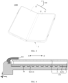
- FIG. 1, FIG. 2 , and FIG. 3 are perspective views of an electronic device 1000 according to some embodiments of this application.
- the electronic device 1000 is a mobile phone with a foldable screen.
- FIG. 1 is a structural diagram of the electronic device 1000 in a fully unfolded state
- FIG. 2 is a structural diagram of the electronic device 1000 in a folded state
- FIG. 3 is a structural diagram of the electronic device 1000 in an intermediate state.
- the electronic device 1000 may be divided into an inner folding device and an outer folding device.
- the inner folding device means that the electronic device 1000 can be folded to a light exit side of the display panel 1.
- the display panel 1 is located inside the electronic device 1000, and an image displayed by the display panel 1 cannot be viewed.
- the display panel 1 is exposed and an image displayed by the display panel 1 can be viewed.
- the outer folding device means that the electronic device 1000 can be folded to a non-light-exit side of the display panel 1.
- the display panel 1 is located outside the electronic device 1000, and an image displayed by the display panel 1 can be viewed.
- the light exit side of the display panel 1 refers to a side on which the display panel 1 is configured to display an image.
- the non-light-exit side of the display panel 1 refers to a side in the display panel 1 opposite to the light exit side.
- the electronic device may also be an electronic device with a curved screen.
- "Curved" means that two opposite ends of the electronic device are bent to the non-light-exit side, and a remaining part is flat. This helps to increase a viewing angle of the electronic device with a curved screen.
- the electronic device includes a display assembly, and the display assembly includes a display panel.
- the display panel is configured to display an image.
- the display panel is an OLED display panel.
- the display panel is a QLED display panel.
- the display panel is a quantum dot photoluminescent display panel.
- the display panel is a flexible display panel, and the flexible display panel is bendable. That is, in a case that the electronic device is a foldable electronic device, the flexible display panel may be unfolded or folded accordingly while the electronic device is being unfolded or folded; and in a case that the electronic device is an electronic device with a curved screen, two opposite ends of the display panel are bent toward the non-light-exit side of the display panel, and a remaining part of the display panel is flat.
- the display assembly further includes a support plate disposed on the non-light-exit side of the display panel.
- the support plate includes at least one first part, and the first part is flat.
- the support plate may include one or more first parts.
- the support plate may include one first part.
- the support plate may include a plurality of first parts.
- the first part includes a plane part and a groove part connected to each other.
- a plurality of grooves are disposed on a side, away from the display panel, of the groove part.
- a depth of the groove is less than a thickness of the plane part in a thickness direction of the display panel.
- the groove part is disposed in the first part of the support plate and grooves are disposed on the side, away from the display panel, of the groove part. Therefore, a weight of the support plate can be effectively reduced, and a weight of the display assembly and the electronic device can be further reduced.
- the electronic device 1000 is, for example, a mobile phone with a foldable screen, and a structure of the electronic device 1000 will be schematically described with reference to the following drawings.
- FIG. 1, FIG. 2 , and FIG. 3 respectively show an overall structure of the electronic device 1000
- FIG. 4 shows a sectional structure of the electronic device 1000 shown in FIG. 1 in a direction A-A'
- FIG. 5 shows a partial sectional structure of the electronic device 1000 shown in FIG. 1 in a direction B-B'.
- a fold-line-shape dashed line in FIG. 5 represents that a part of the structure of the electronic device 1000 is omitted.
- the electronic device 1000 includes a display assembly 100, and the display assembly 100 includes a display panel 1.
- the display panel 1 may have a plurality of first display parts 11, and each first display part 11 may be planar or flat.
- the display panel 1 may further have at least one second display part 12, and each first display part 11 is, for example, in a strip shape.
- the second display part 12 may be located between two adjacent first display parts 11, and the second display part 12 and the two adjacent first display part 11 are connected to each other and have an integral structure.
- the second display part 12 is bent, the first display part 11 is basically not bent, and the first display part 11 can rotate around the second display part 12 connected to the first display part 11.
- the display panel 1 is also in the fully unfolded state.
- the first display part 11 and the second display part 12 may be alternately arranged in a direction.
- a quantity of the first display parts 11 and a quantity of the second display parts 12 may be determined based on a quantity of folding times of the electronic device 1000. For example, the electronic device 1000 is folded only once, and correspondingly, the quantity of the first display parts 11 may be two, and the quantity of the second display parts 12 may be one. For another example, the electronic device 1000 may be folded twice. Correspondingly, the quantity of the first display parts 11 may be three, and the quantity of the second display parts 12 may be two.
- the display panel 1 has two first display parts 11 and one second display part 12.
- the second display part 12 is located between the two first display parts 11.
- the first display part 11 and the second display part 12 may be alternately arranged in a first direction X, and the second display part 12 may extend in a second direction Y.
- both the first display parts 11 can rotate around the second display part 12, that is, a rotation axis of the first display part 11 is parallel to the second direction Y. Therefore, the display panel 1 and the electronic device 1000 can be folded or unfolded.
- Both the first direction X and the second direction Y are parallel to a plane where the display panel 1 is located, and the first direction X and the second direction Y are perpendicular to each other.
- a third direction Z is a thickness direction of the display panel 1, and is perpendicular to both the first direction X and the second direction Y.
- the display assembly 100 further includes a middle frame 3 disposed on the non-light-exit side of the display panel 1.
- the middle frame 3 may include a middle plate (such as a metal middle plate) and a frame disposed surround an edge of the metal middle plate.
- a thickness of the frame in a third direction Z is greater than that of the middle plate in the third direction Z.
- the middle plate and the frame form two opposite grooves.
- the display panel 1 may be located in one of the grooves, and the light exit side of the display panel 1 is opposite to the middle plate.
- a manner of connection between the frame and the middle plate includes but is not limited to soldering, clamping, and integral injection molding.
- a material of the middle plate may include but is not limited to aluminum, aluminum alloy, stainless steel, or the like.
- a material of the frame may include but is not limited to metal, glass, plastic, ceramic, or the like.
- middle frame 3 may be rotated while the electronic device 1000 is being folded.
- the display assembly 100 further includes a protective cover plate 4 disposed on the light exit side of the display panel 1.
- the protective cover plate 4 is configured to protect the display panel 1.
- the protective cover plate 4 may be bonded to a surface of the display panel 1 by sealant.
- the protective cover plate 4 may be made of a transparent film material, so that the protective cover plate 4 is bendable.
- the protective cover plate 4 can be folded accordingly while the electronic device 1000 is being folded.
- a material of the protective cover plate 4 includes but is not limited to polyimide and the like.
- the display assembly 100 further includes a flexible printed circuit board 5 bound to the display panel 1.
- the flexible printed circuit board 5 may be located in a cavity enclosed by the display panel 1 and the middle frame 3.
- the flexible printed circuit board 5 may include a plurality of devices 51.
- the device 51 may include a resistor, a capacitor, an integrated circuit (Integrated Circuit, IC), or the like.
- the flexible printed circuit board 5 and the display panel 1 may be bound by a COP (Chip On Pi) binding process.
- the display assembly 100 may include a COP outlet line 6 connecting the flexible printed circuit board 5 and the display panel 1.
- the flexible printed circuit board 5 and the display panel 1 may be bound by a COF (Chip On Film) binding process.
- the display assembly 100 may include a chip on film 6 connecting the flexible printed circuit board 5 and the display panel 1.
- the electronic device 1000 further includes a front cover 200.
- the front cover 200 may be located on a side, away from the middle frame 3, of the protective cover plate 4 and is connected to the middle frame 3.
- the front cover 200 may shield a connection position between the display panel 1 and the middle frame 3 and a connection position between the cover plate 4 and the middle frame 3.
- a spacing may exist between the front cover 200 and a surface of the protective cover plate 4, or the front cover 200 and the surface of the protective cover plate 4 may contact each other but be not sealed. In this way, it can be prevented, while the electronic device 1000 is being folded, that the front cover 200 hinders bending of the display panel 1 and the protective cover plate 4.
- a material of the front cover 200 may be an insulating material.
- the electronic device 1000 further includes a back cover, a battery, an optical device (such as an image collector), and the like.
- the back cover may be disposed on a side, away from the front cover 200, of the middle frame 3, and enclose a cavity with the middle frame 3.
- the battery, the optical device, and the like may be located in the cavity enclosed by the middle frame 3 and the back cover.
- the optical device may collect light through a through hole 7 in a support plate 2.
- a support plate 2 reference may be made to the following description, and details are not described herein again.
- the display assembly 100 further includes the support plate 2.
- the support plate 2 is disposed on the non-light-exit side of the display panel 1 and is located between the display panel 1 and the middle frame 2.
- the support plate 2 and the display panel 1 may be bonded together, for example, by sealant.
- a COP outlet line or chip on film 6 in the display assembly 100 may be bent between the support plate 2 and the middle frame 3. Therefore, the flexible printed circuit board 5 in the display assembly 100 is located between the support plate 2 and the middle frame 3.
- the display assembly 100 further includes an adhesive 7, and the flexible printed circuit board 5 may be bonded to the support plate 2 by the adhesive 7.
- the support plate 2 can provide support and protect the display assembly 100 and the electronic device 1000, to reduce an impact force on the display assembly 100.
- the support plate 2 may be located, for example, between the back cover and the middle frame.
- the support plate 2 has good toughness. While the display panel 1 is being unfolded or folded, the support plate 2 may be unfolded or folded accordingly.
- the support plate 2 has good rigidity.
- the support plate 2 can support the display panel 1 and maintain a shape of the display panel 1. For example, when the display panel 1 is in the fully unfolded state, folded state, or intermediate state, the support plate 2 can keep the display panel 1 in the fully unfolded state, folded state, or intermediate state, to prevent a change in a state of the display panel 1.
- the support plate 2 may include at least one second part 22, and each second part 22 is, for example, in a strip shape.
- the support plate 2 may further include a plurality of first parts 21, and each first part 21 may be flat.
- the second part 22 may be located between two adjacent first parts 22, and the second part 22 and the two adjacent first parts 21 are connected to each other and have an integral structure. It should be noted that the first part 21 is always flat when the display panel 1 is in the fully unfolded state, folded state, intermediate state, or any other state.
- the second part 22 is bent, the first part 21 is basically not bent, and the first part 21 can rotate around the second part 22 connected to the first part 21.
- the support plate 2 is also in the fully unfolded state.
- the first part 21 and the second part 22 may be alternately arranged in a direction.
- the first display part 11 of the display panel 1 is opposite to the first part 21 of the support plate 2, and the second display part 12 of the display panel 1 is opposite to the second part 22 of the support plate 2.
- “opposite” means that an orthogonal projection of the first display part 11 on a plane where the display panel 1 is located at least partially overlaps an orthogonal projection of the first part 21 of the support plate 2 on the plane where the display panel 1 is located.
- An orthogonal projection of the second display part 12 on the plane where the display panel 1 is located at least partially overlaps an orthogonal projection of the second part 22 of the support plate 2 on the plane where the display panel 1 is located.
- the second part 22 of the support plate 2 is also bent, that is, a rotation axis of the second part 22 of the support plate 2 is parallel to the second direction Y and is parallel to a rotation axis of the first display part 11.
- the second part 22 of the support plate 2 forms support on the second display part 12
- the first part 21 of the support plate 2 forms support on the first display part 11.
- a quantity of the first parts 21 is the same as that of the first display parts 11 in the display panel 1
- a quantity of the second parts 22 is the same as that of the second display parts 12 in the display panel 1.
- a support plate 2 has one second part 22 and two first parts 21.
- the second part 22 is located between the two first parts 21.
- the first part 21 and the second parts 22 may be alternately arranged in a first direction X, and the second part 22 may extend in a second direction Y
- a material of the support plate 2 includes, for example, a metal material.
- the metal material may include stainless steel, titanium alloy, or the like.
- the material of the support plate 2 may also include another material with certain toughness and rigidity.
- Density of the metal material is relatively great, and an area of an orthogonal projection of the support plate 2 on a plane where a display panel 1 is located is relatively large. Therefore, the weight of the support plate 2 is relatively great, causing the weight of a display assembly 100 and an electronic device 1000 is relatively great.
- At least one first part 21 includes a plane part 211 and a groove part 212.
- a plurality of grooves G are disposed on a side, away from the display panel 1, of the groove part 212.
- only one groove G is disposed on a side, away from the display panel 1, of the groove part 212.
- the groove part 212 further includes a separation sub-part H located between two adjacent grooves G, and the separation sub-part H is configured to separate grooves G on two opposite sides of the separation sub-part H.
- the separation sub-part H and the plane part 211 are connected to each other and have an integral structure.
- a quantity of the first parts 21 provided with the groove part 212 may be one, two, or more.
- one, two, or more groove parts 212 may be disposed.
- the support plate 2 includes two first parts 21. As shown in FIG. 6 and FIG. 11 to FIG. 15 , the groove part 212 is disposed in one of the two first parts 21. As shown in FIG. 10 and FIG. 16 , the groove part 212 is provided in each of the two first parts 21. It can be understood that, compared with a support plate not provided with a groove, in this application, after a groove G is disposed in the first part 21, a part, of the support plate, not provided with a groove is removed. In this way, the part, of the support plate 2, not provided with the groove G may be configured to form a support, support for the display assembly 100 and the electronic device 100 can be provided, and increase impact resistance may be improved, and the weight of the support plate 2 can be reduced effectively. Therefore, the weight of the display assembly 100 and the electronic device 1000 can be reduced.
- the groove G is disposed on a side, away from the display panel 1, of the first part 21.
- a depth of the groove G is less than a thickness of the plane part 211.
- the groove G includes a bottom surface S1.
- the depth of the groove G is less than the thickness of the plane part 211, it can be ensured that a spacing exists between the bottom surface S1 and a side surface, of the first part 21, close to the display panel 1. It can be further ensured that the groove G does not penetrate the first part 21, and a side surface, of the first part 21, close to the display panel 1 is a flat surface.
- the depth of the groove G is half of the thickness of the plane part 211.
- an actual depth of the groove G is not limited.
- the side surface, of the first part 21, close to the display panel 1 is the flat surface.
- a spacing between each position of the first part 21 and the display panel 1 may be equal, and then the support plate 2 and the display panel 1 may be bonded together by sealant with an equal thickness.
- a first spacing M exists between an edge of the groove part 212 including the plurality of grooves G and an edge of the first part 21 of the support plate 2. That is, in the second direction Y, both ends of the groove G do not extend to an edge, perpendicular to the second direction Y, of the first part 21, and do not penetrate a side wall, of the first part 21 of the support plate 2, parallel to an XZ plane. In this way, the plane part 211 is disposed surround the groove part 212. Therefore, the thickness, of a part of the first part 21, close to an edge will not decrease, thereby preventing reduction of the support strength of the support plate 2.
- a first spacing exists between an edge of the groove G and an edge of the first part 21, that is, the plane part 211 exists between the edge of the groove G and the edge of the first part 21. Therefore, reduction of the thickness of an edge of the support plate 2 can be prevented by the plane part 211, and decline of the support strength of the support plate 2 can be further prevented.
- the support plate 2 is disposed on the non-light-exit side of the display panel 1, the groove part 212 is disposed in the first part 21 of the support plate 2, the groove G is disposed on a side, away from the display panel 1, of the groove part 212, and a depth of the groove G is limited in a thickness direction of the display panel 1, In this way, the depth of the groove G is less than a thickness of the plane part 211, and the weight of the support plate 2 can be reduced effectively while good impact resistance of the support plate 2 is ensured. Therefore, the weight of the display assembly 100 and the electronic device 1000 can be reduced while good impact resistance of the display assembly 100 and the electronic device 1000 is ensured.
- the groove part 212 may be selectively disposed in some of the first parts 21.
- the weight of a corresponding part for example, a part located on left and right sides of the electronic device 1000 in FIG. 1
- a weight difference from the corresponding part different from the first part 21 may be reduced.
- a groove G in a second direction Y, only one edge of a groove G may not penetrate an edge of a first part 21, that is, in the second direction Y, the foregoing first spacing M exists between only one edge of the groove G and the edge of the first part 21.
- two grooves G are arranged at an interval, namely, a first groove Ga and a second groove Gb.
- the first groove Ga and the second groove Gb respectively extend to adjacent edges of the first part 21 in opposite directions, and respectively penetrate corresponding edges of the first part 21. That is, two adjacent edges of the first groove Ga and the second groove Gb do not penetrate corresponding edges of the first part 21.
- the first groove Ga and the second groove Gb respectively penetrate two edges of the first part 21.
- the first groove Ga and the second groove Gb are arranged at an interval, that is, a spacing exists with the same thickness as that of a plane part 211 between the first groove Ga and the second groove Gb, the spacing still helps to increase the support strength of the first part 21. That is, in the second direction Y, the groove G does not continuously extend from one side edge to an opposite other side edge. Therefore, the support strength of a first part 21 of the support plate 2 will not be reduced.
- the first spacing M may be 0.5mm, 1mm, 2mm, 3mm, 4mm, 5mm, 6mm, 7mm, 8mm, 9mm, 10mm, and the like.
- the first spacing M may be equal or unequal in a first direction X. This is not specifically limited in this application.
- a second spacing N exists between an edge of the groove G and an edge of the first part 21, where N ⁇ 0.2mm.
- the second spacing N may be 0.5mm, 1mm, 2mm, 3mm, 4mm, 5mm, 6mm, 7mm, 8mm, 9mm, 10mm, and the like.
- the second spacing N may be equal or unequal in the second direction Y. This is not specifically limited in this application.
- first spacing M and second spacing N each refers to a minimum spacing between an edge of the groove G and an edge of the first part 21.
- first spacing M and second spacing N each refers to a minimum spacing between an edge of the groove G and an edge of the first part 21.
- an edge of the groove G is a curve
- a spacing between a point of the edge closest to an edge of the first part 21 and an edge of the first part 21 shall prevail.
- the support plate 2 may be bonded to and fixed to another component.
- first spacing M and both the second spacing N are greater than or equal to 1mm
- the back adhesive is pasted to the support plate 2
- a bonding area is increased, which helps to increase the bonding strength, thereby increasing the structural reliability of a device.
- a ratio of a sum of coverage areas of a plurality of grooves G on the first part 21 to an area of the first part 21 is less than or equal to 4:5.
- the plurality of grooves G can occupy 80% of the area of the first part 21 at most.
- a region, where no groove G is disposed, on the first part 21 occupies 20% of the area of the first part 21.
- the plane part 211 is disposed surround a groove part 212.
- the weight of the support plate 2 can be reduced to the maximum extent.
- spacings including the first spacing and the second spacing
- the plane part 211 forms an annular structure surround the plurality of grooves G
- a coverage area of the groove G on the first part 21 refers to an area occupied by a notch of the groove G on a surface of the first part 21 in a third direction Z.
- a coverage area of the groove G on the first part 21 refers to an area of a vertical projection of the notch of the groove G on the first part 21.
- a sum of areas of the plurality of grooves G may occupy 75%, 70%, 65%, 60%, 55%, 50%, 45%, 40%, and the like of the area of the first part 21, which is not specifically limited in this application.
- the groove G further includes a side surface S2 connected to the bottom surface S1.
- An angle exists between the bottom surface S1 and the side surface S2, and the angle is greater than or equal to 90°.
- the angle between the bottom surface S1 and the side surface S2 is equal to 90°.
- a sectional shape of the groove G may be a rectangle or square.
- solution corresponding to a material of the support plate 2 may be used, to etch a specific position of the first part 21, to obtain the groove part 212 including the plurality of grooves G.
- the solution (or liquid medicine) may etch the first part 21 in the third direction Z in the same amount. Therefore, the angle between the bottom surface S1 and the side surface S2 in the formed groove G is equal to 90°. This helps preparation and formation of the groove G.
- the angle between the bottom surface S1 and the side surface S2 is greater than 90°.
- a sectional shape of the groove G may be trapezoidal.
- the side surface S2 of the groove G can buffer transmission of an impact force, preventing stress concentration at a junction of the bottom surface S1 and the side surface S2, and helping to prolong service life of the support plate 2.
- a plurality of grooves G in the groove part 212 may be arranged in an array.
- the plurality of grooves G may be arranged in at least one row in the first direction X and arranged in at least one row in the second direction Y
- the plurality of grooves G in the groove part 212 are arranged in a row in the first direction X and arranged in a plurality of rows in the second direction Y
- a plurality of grooves G in a groove part 212 are arranged in a plurality of rows in a first direction X and arranged in a plurality of rows in a second direction Y
- the plurality of grooves G are arranged in an array. Accordingly, arrangement regularity of the plurality of grooves G may be increased, and a difficulty in preparing and forming the grooves G may be reduced.
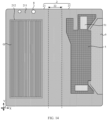
- a shape of the orthogonal projection of the grooves G on the plane where the first part 21 is located includes a strip shape (as shown in FIG. 6 and FIG. 10 ), a curve (as shown in FIG. 11 ), a circle (as shown in FIG. 12 ), an ellipse, or a square.
- a length direction (or an extension direction) and arrangement of the grooves G may be the same or similar.
- the plurality of grooves G in the groove part 212 are arranged in parallel and at intervals.
- the shape of the orthogonal projection of the grooves G on the plane where the first part 21 is located is a strip shape.
- a length direction of each groove G is the second direction Y
- a vertical direction of the length direction of each groove G is the first direction X.
- the plurality of grooves G in the groove part 212 are arranged in parallel and at intervals in the first direction X.
- the length direction of the groove G may also have an angle with the second direction Y, and a range of the angle is 0°-90°.
- the shape of the orthogonal projection of the grooves G on the plane where the first part 21 is located is a curve.
- the length direction of each groove G has an angle with the first direction X or the second direction Y.
- the vertical direction of the length direction of the groove G also has an angle with the first direction X or the second direction Y.
- the plurality of grooves G in the groove part 212 are arranged in parallel and at intervals in the first direction X.
- the length direction of the groove G in this example may also be the first direction X or the second direction Y.
- a part (that is, a separation sub-part H) of the groove part 212 except the grooves G may be in a plurality of strip shapes, and ends of the plurality of strip shapes are connected to each other. Therefore, support is provided by the separation sub-part H between two adjacent grooves G in the groove part 212, to ensure impact resistance of the display assembly 100 and the electronic device 1000, and the arrangement regularity of the grooves G can be increased. Accordingly, relatively many grooves G can be disposed in the groove part 212, an area ratio of the grooves G in the groove part 212 can be increased, the weight of the support plate 2 can be reduced effectively, and the weight of the display assembly 100 and the electronic device 1000 can be reduced effectively.
- the shape of the orthogonal projection of the grooves G on the plane where the first part 21 is located is a circle, an ellipse, or a square
- arrangement of the grooves G may be the same or similar.
- the shape of the orthogonal projection of the grooves G on the plane where the first part 21 is located is a circle.
- a plurality of grooves G in a groove part 212 may be arranged in an array, that is, the plurality of grooves G may be arranged in a plurality of columns in a first direction X and arranged in a plurality of rows in a second direction Y
- a part (that is, a separation sub-part H) of the groove part 212 except the grooves G may be in a grid shape. Accordingly, not only continuity of the separation sub-part H between any two adjacent grooves G in the groove part 212 can be increased, the support effect of the support plate 2 and impact resistance of the display assembly 100 and the electronic device 1000 can be ensured, but also arrangement regularity of the grooves G can be increased. Therefore, relatively many grooves G can be disposed in the groove part 212, and the weight of the support plate 2 and the weight of the display assembly 100 and the electronic device 1000 can be reduced effectively.
- a ratio of a spacing L2 between two adjacent grooves G to a dimension L1 of a groove G in a set direction is greater than or equal to 2:3.
- the set direction is a direction parallel to the plane where the first part 21 is located. In other words, the set direction is parallel to the plane where the first part 21 is located, that is, the set direction is parallel to a YX plane.
- the spacing L2 between two adjacent grooves G refers to a spacing between two adjacent side surfaces S2 of two adjacent grooves G.
- the set direction and the dimension L1 of the groove G in the set direction are related to a shape of the orthogonal projection of the grooves G on the plane where the first part 21 is located.
- the shape of the orthogonal projection of the grooves G on the plane where the first part 21 is located is a strip shape or curve
- the set direction is a vertical direction of the length direction of the groove G
- the dimension L1 of the groove G in the set direction is a spacing between two opposite side surfaces of the groove G in a vertical direction of the length direction of the groove G.
- the shape of the orthogonal projection of the grooves G on the plane where the first part 21 is located is a circle, an ellipse, or a square
- the set direction is a diameter direction of the circle, a long axis direction of the ellipse, or a diagonal direction of the square
- the dimension L1 of the groove G in the set direction is a diameter value of the circle, a long axis value of the ellipse, or a diagonal length value of the square.
- the ratio of a spacing L2 between two adjacent grooves G to a dimension L1 of the groove Gin a set direction is may be 2:3, 1: 1, 4:3, 3:2, or the like.
- the spacing L2 between two adjacent grooves G is relatively small.
- a span between two adjacent grooves G is relatively small, and when the support plate 2 or the display assembly 100 is impacted, the separation sub-part H in the groove part 212 between any two adjacent grooves G may form a bridge-pier-like support.
- the spacing L2 between two adjacent grooves G is relatively big.
- the span between two adjacent grooves G is relatively big, and when the support plate 2 or the display assembly 100 is impacted, it can be ensured that the separation sub-part H in the groove part 212 between any two adjacent grooves G may provide relatively good support.
- a value range of the dimension L1 of the groove G in the set direction is 0.8mm-1.2mm.
- the dimension L1 of the groove G in the set direction may be 0.8mm, 0.9mm, 1mm, 1.1mm, 1.2mm, or the like.
- a value range of the spacing L2 between two adjacent grooves G is 0.8mm-1.2mm.
- the spacing L2 between two adjacent grooves G may be 0.8mm, 0.9mm, 1mm, 1.1mm, 1.2mm, or the like.
- the spacing L2 between two adjacent grooves G is greater than or equal to the dimension L1 of the groove G in the set direction. That is, the ratio of a spacing L2 between two adjacent grooves G to a dimension L1 of the groove G in a set direction is greater than or equal to 1.
- the value range of dimension L1 of the groove G in the set direction is 0.8mm-1.2mm
- the value range of the spacing L2 between two adjacent grooves G is 0.8mm-1.2mm.
- a value of the spacing L2 between two adjacent grooves G is greater than or equal to a value of the dimension L1 of the groove G in the set direction.
- At least some of the plurality of grooves G in the groove part 212 are arranged at an equal interval.
- the plurality of grooves G may be arranged at an equal interval.
- some of the plurality of grooves G may be arranged at an equal interval, and the others may be arranged at an unequal interval.
- a spacing between at least two grooves G is not equal to a spacing between others of the grooves G.
- a plane part 211 in a first part 21 provided with a groove G, includes at least one adsorption sub-part 213.
- the at least one adsorption sub-part 213 and a plurality of grooves G in a groove part 212 are staggered.
- the first part 21 provided with a groove G may include one, two, three, four, or more adsorption sub-parts 213.
- the groove G does not penetrate or extend to the adsorption sub-part 213, and an orthogonal projection of the grooves G on a plane where a support plate 2 is located does not overlap an orthogonal projection of the adsorption sub-part 213 on the plane where the support plate 2 is located.
- a side surface, away from a display panel 1, of the adsorption sub-part 213 is a first surface.
- the first surface is a continuous plane.
- the "continuous” means that the first surface is not disconnected.
- the “plane” means that the first surface has relatively great flatness basically without unevenness.
- FIG. 18 and FIG. 21 show the first part 21 of the support plate 2, but does not show the display panel 1. It can be known with reference to FIG. 4 and FIG. 5 that the display panel 1 is located below the support plate 2.
- the display panel 1, support plate 2, protective cover plate 4, flexible printed circuit board 5, COP outlet line or chip on film 6, and adhesive 7 are first assembled to form a module, and then the module is assembled with the middle frame 3, front cover 200, and the like.
- the module will be placed in an accommodating housing (or protective housing), with the protective cover plate 4 facing down and the flexible printed circuit board 5 facing up.
- the module needs to be taken out the accommodating housing.
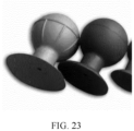
- the module may be taken out by a vacuum adsorption ball (as shown in FIG. 23 ).
- a vacuum adsorption ball (as shown in FIG. 23 ).
- an adsorption ball head of the vacuum adsorption ball may be pinched, to remove air in the adsorption ball head, and then an adsorption ball chuck of the vacuum adsorption ball is placed at a position of the adsorption sub-part 213, and then the adsorption ball head is loosened.
- a low-pressure region is formed inside the adsorption ball head, and an external high-pressure region is formed outside the adsorption ball head.
- a pressure difference between the inside and outside of the adsorption ball head enables an intensity of pressure between the adsorption ball chuck and a first surface of the adsorption sub-part 213, so that the adsorption ball chuck and the first surface of the adsorption sub-part 213 are attached together.
- the module may be taken out of the accommodating housing. In this way, picking (or withdrawing) or touching the module by hand of an employee can be prevented, to reduce a damage rate of the module.
- the adsorption sub-part 213 and the groove G are staggered, and the first surface of the adsorption sub-part 213 is set as a continuous plane. Therefore, air leakage between the adsorption ball chuck and the first surface of the adsorption sub-part 213 can be prevented, and it can be prevented that the module cannot be taken out of the accommodating housing through adsorption by the vacuum adsorption ball.
- the vacuum adsorption ball may be arranged on each adsorption sub-part 213.
- a plurality of vacuum adsorption balls may be configured to adsorb and pick up the module. This helps to increase a success rate of adsorption and pickup.
- the adsorption sub-part 213 does not overlap the plurality of grooves G in the groove part 212. In addition or alternatively, a spacing exists between the adsorption sub-part 213 and the plurality of grooves G in the groove part 212.
- the adsorption sub-part 213 does not contact its adjacent groove G, and the groove G does not extend into the adsorption sub-part 213.
- a part in the plane part 211 except the adsorption sub-part 213 is a set part.
- a side surface, away from the display panel 1, of the set part is a second surface, and the second surface is flush with the first surface.
- a thickness direction of the display panel 1 that is, a third direction Z
- a thickness of the adsorption sub-part 213 is equal to a thickness of the set part.
- the vacuum adsorption ball is configured to pick up the module, to reduce the damage rate of the module, and formation of a difference in level between the side surface, of the adsorption sub-part 213, close to the display panel 1 and the side surface, of the set part, close to the display panel 1 can be prevented, and an adverse effect on structural stability of the display panel 1 can be prevented.
- a separation sub-part H, in the groove part 212, located between two adjacent grooves G and the adsorption sub-part 213 are connected to each other and have an integral structure.
- a region where the adsorption sub-part is to be formed may be planned but is not etched, and only a region other than the region is etched, so that the adsorption sub-part 213 may be naturally formed. This not only helps to reduce a difficulty in forming the adsorption sub-part 213, but also reduce the amount of solution for forming the groove G through etching, thereby reducing costs.
- a shape of a connecting line of ends, close to the adsorption sub-part 213, of a plurality of grooves G in the groove part 212 is complementary to a shape of a boundary, close to the plurality of grooves G, of the adsorption sub-part 213.
- a spacing between the connecting line of ends, close to the adsorption sub-part 213, of the plurality of grooves G in the groove part 212 and the boundary, close to the plurality of grooves G, of the adsorption sub-part 213 can be reduced, which can not only enable an area of the adsorption sub-part 213 to correspond to the adsorption ball chuck, to ensure that the vacuum adsorption ball can successfully adsorb and pick up the module, but also enable the groove part 212 to have a relatively great area ratio in the first part 21, reducing the weight of the support plate 2 and the weight of the display assembly 100 and the electronic device.
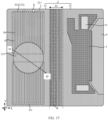
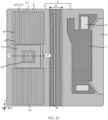
- a shape of the adsorption sub-part 213 includes a circle (as shown in FIG. 17 ), a square (as shown in FIG. 22 ), a ring (as shown in FIG. 19 ), or a frame (as shown in FIG. 20 ).
- the shape of the adsorption sub-part 213 is not limited to the foregoing example, but may be flexibly set based on a size, dimension, or shape of the vacuum adsorption ball.
- the adsorption sub-part 213 surrounds at least one groove G.
- a shape of the groove G is a ring or frame.
- one groove G, two grooves G, or even all grooves G may be dispose inside the adsorption sub-part 213 and surrounded by the adsorption sub-part 213.
- a quantity of grooves G surrounded by the adsorption sub-part 213 may be selected and disposed based on actual needs, provided that adsorption and pickup of the module by the vacuum adsorption ball is not affected.
- the groove part 213 includes a first groove group G1, and a quantity of the first groove groups G1 may be at least two.
- Each first groove group G1 includes at least two grooves G.
- the quantity of the first groove groups G1 may be two, three, or more.
- a quantity of grooves G included in each first groove group G1 may be two, three, or more.
- at least two of the first groove groups G1 may be sequentially arranged in a second direction Y.
- the at least two first grooves G1 may also be arranged in another manner.
- the adsorption sub-part 213 is located between the at least two first groove groups G1.
- the at least two first groove groups G1 are arranged in a row, and the adsorption sub-part 213 is located between two of the first groove groups G.
- the shape of the adsorption sub-part 213 may be a circle, a square, a ring, or a frame.
- the module is picked up by the vacuum adsorption ball, it can be prevented that the module is inclined to a great extent.
- the adsorption sub-part 213 further surrounds a second groove group G2, and the second groove group G2 includes at least two grooves G.
- a quantity of grooves G included in each second groove group G2 may be two, three, or more.
- the second groove group G2 is located between the at least two first groove groups G1.
- the two first groove groups G1 are sequentially arranged in the second direction Y, and the second groove group G2 may be located between two of the first groove groups G1 and arranged in a row together with the at least two first groove groups G1.
- the adsorption sub-part 213 surrounds the second groove group G2.
- the shape of the adsorption sub-part 213 may be a ring or a frame.
- a quantity of the second groove groups G2 may be, for example, the same as that of the adsorption sub-parts 213, so that each adsorption sub-part 213 may surround one second groove group G2.
- the weight of the support plate 2 can be further reduced, and the weight of the display assembly 100 and the electronic device can be reduced.
- an orthogonal projection of the flexible printed circuit board 5 in the display assembly 100 on the support plate 2 and at least one adsorption sub-part 213 are staggered. That is, the orthogonal projection and the at least one adsorption sub-part 213 do not overlap.
- a plurality of openings K are disposed in a second part 22 of the support plate 2.
- the plurality of openings K may penetrate the support plate 2.
- the plurality of openings K may be configured to reduce stress concentration in the second part 22.
- disposing of the plurality of openings K also helps to reduce the weight of the support plate 2 and the weight of the display assembly 100 and the electronic device.
Landscapes
- Engineering & Computer Science (AREA)
- Computer Hardware Design (AREA)
- Theoretical Computer Science (AREA)
- General Engineering & Computer Science (AREA)
- Human Computer Interaction (AREA)
- Physics & Mathematics (AREA)
- General Physics & Mathematics (AREA)
- Signal Processing (AREA)
- Devices For Indicating Variable Information By Combining Individual Elements (AREA)
- Electroluminescent Light Sources (AREA)
Abstract
Description
- This application claims priority to
Chinese Utility Model Patent Application No. 202220150786.5, filed with the China National Intellectual Property Administration on January 18, 2022 - This application relates to the field of display technologies, and in particular, to a display assembly and an electronic device.
- With the development of science and technology, a bendable flexible screen has emerged, so that more product forms of electronic devices can be developed.
- In the related technologies, a protective cover plate of an electronic device is usually bendable and has a small thickness, which causes poor impact resistance of the protective cover plate. Therefore, at present, a support plate is disposed on the back of the flexible screen, to support and protect the flexible screen by using the support plate and increase the impact resistance of the electronic device.
- However, the support plate has a great density and area, which causes a large weight of the support plate, and further leads to a large increase in an overall weight of the electronic device.
- Embodiments of this application provide a display assembly and an electronic device, and are used to reduce a weight of the display assembly and the electronic device.
- To achieve the foregoing objective, the following technical solutions are used in the embodiments of this application.
- According to a first aspect, a display assembly is provided. The display assembly includes a display panel and a support plate. The support plate is disposed on a non-light-exit side of the display panel. The support plate includes at least one first part, and the first part is flat. The first part includes a plane part and a groove part connected to each other, a plurality of grooves are disposed on a side, away from the display panel, of the groove part, and a depth of the groove is less than a thickness of the plane part in a thickness direction of the display panel.
- According to the display assembly provided in some embodiments of this application, the support plate is disposed on the non-light-exit side of the display panel, the groove part is disposed in the first part of the support plate, grooves are disposed on a side, away from the display panel, of the groove part, and the depth of the groove is limited in a thickness direction of the display panel. In this way, the depth of the groove is less than the thickness of the plane part, and the weight of the support plate can be reduced effectively while good impact resistance of the support plate is ensured. Therefore, the weight of the display assembly and the weight of the electronic device using the display assembly can be reduced while the good impact resistance of the display assembly is ensured.
- In a possible implementation of the first aspect, the plane part includes at least one adsorption sub-part. The at least one adsorption sub-part and the plurality of grooves G in a groove part are staggered. A side surface, away from the display panel, of the adsorption sub-part panel is a first surface, and the first surface is a continuous plane. In this way, a module including the display panel, the support plate, the protective cover plate, the flexible printed circuit board, a COP outlet line or chip on film, and an adhesive may be taken out of an accommodating housing by a vacuum adsorption ball, to prevent the module from being picked up (withdrawn) by hand of an employee, thus reducing a damage rate of the module. In addition, air leakage between an adsorption ball chuck and a side surface, away from the display panel, of the adsorption sub-part can be prevented, and it can be prevented that the module cannot be taken out of the accommodating housing through adsorption by the vacuum adsorption ball.
- In a possible implementation of the first aspect, a part in the plane part except the adsorption sub-part is a set part, and a side surface, away from the display panel, of the set part is a second surface. The first surface is flush with the second surface. In the thickness direction of the display panel, a thickness of the adsorption sub-part is equal to a thickness of the set part. In this way, the vacuum adsorption ball is configured to pick up the module, to reduce the damage rate of the module, and formation of a difference in level between a side surface, of the adsorption sub-part, close to the display panel and a side surface, of the set part of the plane part, close to the display panel can be prevented, and an adverse effect on structural stability of the display panel can be prevented.
- In a possible implementation of the first aspect, the adsorption sub-part does not overlap the groove. In addition or alternatively, a spacing exists between the adsorption sub-part and the groove. This helps to ensure that the adsorption sub-part and the plurality of grooves in the groove part are staggered, and that the first surface of the adsorption sub-part is a continuous plane.
- In a possible implementation of the first aspect, a shape of the adsorption sub-part includes a circle, a square, a ring, or a frame. In this way, while the vacuum adsorption ball is configured to pick up the module, it can be ensured that intensity of pressure may be generated between each position of the adsorption sub-part and the adsorption ball chuck, to prevent air leakage.
- In a possible implementation of the first aspect, the adsorption sub-part surrounds at least one groove.
- In a possible implementation of the first aspect, a shape of a connecting line of ends, close to the adsorption sub-part, of the plurality of grooves, is complementary to a shape of a boundary, close to the plurality of grooves, of the adsorption sub-part. In this way, it can be ensured that the vacuum adsorption ball can successfully adsorb and pick up the module, and the groove may have a relatively great area ratio in the first part, reducing the weight of the support plate.
- In a possible implementation of the first aspect, the groove part includes at least two first groove groups, each first groove group includes at least two grooves, and the adsorption sub-part is located between the at least two first groove groups. This helps to dispose the adsorption sub-part at a position close to a center of the support plate or the module. When the module is picked up by the vacuum adsorption ball, it can be prevented that the module is inclined to a great extent.
- In a possible implementation of the first aspect, the groove part further includes a second groove group. The second groove group includes at least two grooves and is located between the at least two first groove groups. The adsorption sub-part surrounds the second groove group. In this way, while the module is adsorbed and picked up by the vacuum adsorption ball, the weight of the support plate can be further reduced.
- In a possible implementation of the first aspect, the groove part includes a separation sub-part between two adjacent grooves, and the separation sub-part and the adsorption sub-part are connected to each other and have an integral structure. This not only helps to reduce a difficulty in forming the adsorption sub-part, but also reduce the amount of solution for forming the groove through etching, thereby reducing costs.
- In a possible implementation of the first aspect, the display assembly further includes: a protective cover plate, middle frame, and flexible printed circuit board. The protective cover plate is disposed on a side, away from the support plate, of the display panel, the middle frame is disposed on a side, away from the display panel, of the support plate, and the flexible printed circuit board is bound to the display panel. The flexible printed circuit board is located between the support plate and the middle frame, and an orthogonal projection of the flexible printed circuit board on the support plate and at least one adsorption sub-part are staggered. In this way, it can be prevented that the flexible printed circuit board shields the adsorption sub-part, and an adverse impact on adsorption and pickup of the module by the vacuum adsorption ball can be further prevented.
- In a possible implementation of the first aspect, a ratio of a spacing between two adjacent grooves to a dimension of the groove in a set direction is greater than or equal to 2:3. The set direction is a direction parallel to a plane where the first part is located. In this way, it can be ensured that a part, between any two adjacent grooves, in the first part can provide relatively good support.
- In a possible implementation of the first aspect, a spacing between two adjacent grooves is greater than or equal to a dimension of the groove in a set direction. In this way, a ratio of an area of a part, between two adjacent grooves, in the first part can be increased, and a support effect of the support plate can be ensured.
- In a possible implementation of the first aspect, the groove includes a bottom surface and a side surface connected to the bottom surface. An angle between the bottom surface and the side surface is greater than or equal to 90°. In this way, when the angle is equal to 90°, it helps to prepare and form the groove G, or when the angle is greater than 90°, stress concentration at a joint of the bottom surface and the side surface can be prevented, which helps to prolong service life of the support plate.
- In a possible implementation of the first aspect, a plurality of grooves are arranged in an array. In this way, arrangement regularity of the plurality of grooves G can be increased and a difficulty in preparing and forming the grooves G can be reduced.
- In a possible implementation of the first aspect, a shape of an orthogonal projection of the grooves on the plane where the first part is located includes a strip shape, a curve, a circle, an ellipse, or a square. In this way, the weight of the support plate can be reduced effectively.
- In a possible implementation of the first aspect, a shape of the orthogonal projection of the grooves on the plane where the first part is located includes a strip shape or a curve. In a vertical direction of a length direction of the groove, a plurality of grooves in the groove part are arranged in parallel and at intervals. In this way, arrangement regularity of the grooves can be increased, which helps to dispose relatively many grooves in the groove part and effectively reduce the weight of the support plate.
- In a possible implementation of the first aspect, the support plate includes a plurality of first parts and at least one second part, and the second part is located between two adjacent first parts. The second part is bendable and is capable of driving an adjacent first part to rotate around the second part. In this way, the display assembly is foldable, and an electronic device using the display assembly is foldable.
- In a possible implementation of the first aspect, the display panel has a plurality of first display parts and at least one second display part. The second display part is located between two adjacent first display parts, the first display part is opposite to the first part, and the second display part is opposite to the second part. In this way, when the second display part is bent, the second part will also be bent, and the first part will support the first display part, and the second part will support the second display part.
- In a possible implementation of the first aspect, a plurality of openings are disposed in the second part. In this way, the plurality of openings may be configured to reduce stress concentration in the second part, and the weight of the support plate can be reduced.
- According to a second aspect, some embodiments of this application provide an electronic device, including: the display assembly as described in any possible implementation of the first aspect.
- For technical effects brought by the second aspect, reference may be made to the technical effects brought by different design manners in the first aspect, and details are not described herein again.
- According to a third aspect, a display assembly is provided. The display assembly includes a display panel and a support plate. The support plate is disposed on a non-light-exit side of the display panel. The support plate includes a plurality of first parts and at least one second part, where the second part is located between two adjacent first parts, the first part is flat, the second part is bendable, and the first part is capable of rotating around the second part. A plurality of grooves are disposed on a side, away from the display panel, of the first part, where a depth of the groove is less than a thickness of the support plate in a third direction, and the third direction is a thickness direction of the display panel; and a first spacing exists between an edge of the groove and an edge of the first part in a second direction, and the second direction is a direction parallel to a rotation axis of the first part.
- According to the display assembly provided in some embodiments of this application, the support plate is disposed on the non-light-exit side of the display panel, a plurality of grooves is disposed on a side, away from the display panel, of the first part of the support plate, and a depth of the groove is limited in a thickness direction of the display panel. In this way, the depth of the groove is less than the thickness of the support plate, and a first spacing exists between the edge of the groove and the edge of the first part in the second direction. Therefore, the weight of the support plate can be reduced effectively while good impact resistance of the support plate is ensured. Further, the weight of the display assembly and the weight of the electronic device using the display assembly can be reduced while the good impact resistance of the display assembly is ensured.
- In a possible implementation of the third aspect, a ratio of a sum of areas of the plurality of grooves to an area of the first part is less than or equal to 1:2. In this way, the plurality of grooves occupy 50% of the area of the first part, and because the first spacing exists between the edge of the groove and the edge of the first part, while the support strength of the support plate is ensured, the weight of the support plate can be reduced to the greatest extent, to reduce the weight of the display assembly.
- In a possible implementation of the third aspect, the first spacing is M, and M≥0.2mm.
- In a possible implementation of the third aspect, the first spacing M≥1mm.
- In a possible implementation of the third aspect, a second spacing N exists between an edge of the groove and an edge of the first part in a first direction, N≥0.2mm. The first direction is perpendicular to the second direction and the third direction.
- In a possible implementation of the third aspect, the second spacing N≥1mm.
- In a possible implementation of the third aspect, a ratio of a spacing between two adjacent grooves to a dimension of the groove in a set direction is greater than or equal to 2:3. The set direction is parallel to a plane where the first part is located. In this way, it can be ensured that a part, between any two adjacent grooves, in the first part can provide relatively good support.
- In a possible implementation of the third aspect, a spacing between two adjacent grooves is greater than or equal to a dimension of the groove in a set direction. That is, a ratio of the spacing between two adjacent grooves to the dimension of the groove in the set direction is greater than or equal to 1:1. In this way, a ratio of an area of a part, between two adjacent grooves, in the first part can be increased, and a support effect of the support plate can be ensured.
- In a possible implementation of the third aspect, the groove includes a bottom surface and a side surface connected to the bottom surface. An angle between the bottom surface and the side surface is greater than or equal to 90°. In this way, when the angle is equal to 90°, it helps to prepare and form the groove G, or when the angle is greater than 90°, stress concentration at a joint of the bottom surface and the side surface can be prevented, which helps to prolong service life of the support plate.
- In a possible implementation of the third aspect, a plurality of grooves are arranged in an array. In this way, arrangement regularity of the plurality of grooves G can be increased and a difficulty in preparing and forming the grooves G can be reduced.
- In a possible implementation of the third aspect, a shape of the orthogonal projection of the grooves on the plane where the first part is located includes a strip shape, a curve, a circle, an ellipse, or a square. In this way, the weight of the support plate can be reduced effectively.
- In a possible implementation of the third aspect, a shape of the orthogonal projection of the grooves on the plane where the first part is located includes a strip shape or a curve. The plurality of grooves are arranged in parallel and at intervals in the first direction, and the first direction is perpendicular to the second direction and the third direction. In this way, arrangement regularity of the grooves can be increased, which helps to dispose relatively many grooves in the groove part and effectively reduce the weight of the support plate.
- In a possible implementation of the third aspect, a spacing between at least two grooves is not equal to a spacing between others of the grooves in the first direction. In this way, different spacings may be set between adjacent grooves, to meet different design requirements.
- In a possible implementation of the third aspect, the display panel has a plurality of first display parts and at least one second display part. The second display part is located between two adjacent first display parts, the first display part is opposite to the first part, and the second display part is opposite to the second part. In this way, when the second display part is bent, the second part will also be bent, and the first part will support the first display part, and the second part will support the second display part.
- In a possible implementation of the third aspect, a plurality of openings are disposed in the second part. In this way, the plurality of openings may be configured to reduce stress concentration in the second part, and the weight of the support plate can be reduced.
- According to a fourth aspect, some embodiments of this application provide an electronic device, including: the display assembly as described in any possible implementation of the third aspect.
- For technical effects brought by the fourth aspect, reference may be made to the technical effects brought by different design manners in the third aspect, and details are not described herein again.
- According to a fifth aspect, a display assembly is provided. The display assembly includes a display panel and a support plate. The support plate is disposed on a non-light-exit side of the display panel. The support plate includes plurality of first parts and at least one second part, where the second part is located between two adjacent first parts, the first part is flat, the second part is bendable, and the first part is capable of rotating around the second part. At least one groove is disposed on a side, away from the display panel, of the first part, where a depth of the groove is less than a thickness of the support plate in a third direction, and the third direction is a thickness direction of the display panel; and at least one edge of the groove does not penetrate an edge of the first part in a second direction, and the second direction is a direction parallel to a rotation axis of the first part.
- For technical effects brought by the fifth aspect, reference may be made to the technical effects brought by the third aspect, and details are not described herein again.
- In a possible implementation of the fifth aspect, a plurality of grooves are disposed at intervals on a side, away from the display panel, of the first part.
- In a possible implementation of the fifth aspect, a first spacing exists between an edge of each groove and the edge of the first part in the second direction.
-
-
FIG. 1 is a schematic structural diagram of an electronic device in a fully unfolded state according to an embodiment of this application; -
FIG. 2 is a schematic structural diagram of the electronic device in a folded state according to an embodiment of this application; -
FIG. 3 is a schematic structural diagram of the electronic device in an intermediate state according to an embodiment of this application; -
FIG. 4 is a partial sectional view of the electronic device inFIG. 1 in a direction A-A'; -
FIG. 5 is partial sectional view of the electronic device inFIG. 1 in a direction B-B'; -
FIG. 6 is a schematic structural diagram of a support plate according to an embodiment of this application; -
FIG. 7 is a sectional view of the support plate inFIG. 6 in a direction C-C'; -
FIG. 8 is another sectional view of the support plate inFIG. 6 in a direction C-C'; -
FIG. 9 is still another schematic structural diagram of a support plate according to an embodiment of this application; -
FIG. 10 is yet another schematic structural diagram of a support plate according to an embodiment of this application; -
FIG. 11 is still yet another schematic structural diagram of a support plate according to an embodiment of this application; -
FIG. 12 is a further schematic structural diagram of a support plate according to an embodiment of this application; -
FIG. 13 is a still further schematic structural diagram of a support plate according to an embodiment of this application; -
FIG. 14 is a bottom view of a support plate, flexible printed circuit board, and COP outlet line or chip on film inFIG. 5 ; -
FIG. 15 is another bottom view of a support plate, flexible printed circuit board, and COP outlet line or chip on film inFIG. 5 ; -
FIG. 16 is still another bottom view of a support plate, flexible printed circuit board, and COP outlet line or a chip on film inFIG. 5 ; -
FIG. 17 is yet another bottom view of a support plate, flexible printed circuit board, and COP outlet line or chip on film inFIG. 5 ; -
FIG. 18 is a sectional view of a structure and vacuum adsorption ball shown inFIG. 17 tin a direction D-D'; -
FIG. 19 is still yet another bottom view of a support plate, flexible printed circuit board, and COP outlet line or chip on film inFIG. 5 ; -
FIG. 20 is a further bottom view of a support plate, flexible printed circuit board, and COP outlet line or chip on film inFIG. 5 ; -
FIG. 21 is a sectional view of a structure and vacuum adsorption ball shown inFIG. 20 in a direction E-E'; -
FIG. 22 is a still further bottom view of a support plate, flexible printed circuit board, and COP outlet line or chip on film inFIG. 5 ; and -
FIG. 23 is a schematic structural diagram of a vacuum adsorption ball according to an embodiment of this application. -
1000. electronic device 100. display assembly 200. front cover 1. display panel 11. first display part 12. second display part 2. support plate 21. first part 22. second part 211. plane part 212. groove part 213. adsorption sub-part 3. middle frame 4. protective cover plate 5. flexible printed circuit board 51. device 6. COP outlet line or chip on film 7. adhesive 8. through hole G. groove G1. first groove group G2. second groove group Ga. first groove Gb. second groove H. separation sub-part K. opening - The following describes technical solutions in embodiments of this application with reference to accompanying drawings in embodiments of this application. Apparently, the described embodiments are merely some rather than all embodiments of this application.
- In the embodiments of this application, terms "first" and "second" are used merely for the purpose of description, and shall not be construed as indicating or implying relative importance or implying a quantity of indicated technical features. Therefore, a feature limited by "first" or "second" may explicitly or implicitly include one or more of the features.
- In the embodiments of this application, the term "include", "have", or any other variant thereof is intended to cover non-exclusive inclusion, so that a process, a method, an article, or an apparatus that includes a series of elements includes not only those elements but also other elements that are not explicitly listed, or includes elements inherent to such process, method, article, or apparatus. In a case without more restrictions, for an element limited by the statement "include a...", a process, a method, an article, or an apparatus that includes the element may further include another same element.
- In this application, unless otherwise specified and defined, the term "connection" should be understood in a broad sense. For example, a "connection" may be a fixed connection, may be a detachable connection, or may be integration, and may be a direct connection or an indirect connection implemented by using an intermediate medium. In addition, the term "coupled" may be an electrical connection manner for implementing signal transmission. "Coupled" may be a direct electrical connection, or an indirect electrical connection through an intermediary.
- In the embodiments of this application, "and/or" indicates merely an association relationship for describing associated objects and represents the presence of three relationships. For example, A and/or B may represent the presence of three cases: only A, both A and B, and only B. In addition, the symbol "/" in this specification usually indicates an "or" relationship between the associated objects.
- Moreover, the use of "based on" means open and inclusive, since a process, a step, calculation or other actions "based on" one or more of the conditions or values may be based on an additional condition or exceed the stated values in practice.
- The term "about", "substantially", or "approximately" as used herein includes a stated value and an average value within an acceptable range of deviation of a particular value, and the acceptable range of deviation is determined by a person of ordinary skill in the art while considering measurement in question and errors associated with measurement of a particular quantity (that is, limitations of a measurement system).
- Exemplary implementations are described herein with reference to sectional views and/or plan views as idealized exemplary accompanying drawings. In the accompanying drawings, thicknesses of a layer and a region are increased for clarity. Therefore, variations on shapes relative to that in the accompanying drawings due to, for example, manufacturing technologies and/or tolerances, may be contemplated. Therefore, example implementations should not be construed as being limited to shapes of the regions shown herein, but include a shape deviation due to, for example, manufacturing. For example, an etched region shown as a rectangle generally has a curved feature. Therefore, the regions shown in the accompanying drawings are schematic in nature, and shapes of the regions are not intended to show an actual shape of a region of a device and are not intended to limit the scope of example implementations.
- This application provides an electronic device. The electronic device is, for example, a type of electronic devices with a flexible display panel. For example, the flexible display panel is bendable. For example, two relative ends or a middle part of the flexible display panel are bendable.
- In some examples, the electronic device includes but is not limited to a notebook (notebook), a tablet personal computer (tablet personal computer), a mobile phone (mobile phone), a laptop computer (laptop computer), a personal digital assistant (personal digital assistant, PDA), a personal computer, a navigator, a vehicle-mounted device, a wearable device (such as a smart watch), an augmented reality (Augmented Reality, AR) device, a virtual reality (Virtual Reality, VR) device, and any other products or components with a display function. A specific form of an
electronic device 1000 is not specially limited in this embodiment of this application. - Optionally, the electronic device may be an electroluminescent display device or a photoluminescent display device. In a case that the
electronic device 1000 is the electroluminescent display device, theelectronic device 1000 may be an organic electroluminescent (Organic Light Emitting Diode, OLED) display device or a quantum dot electroluminescent (Quantum Dot Light Emitting Diodes, QLED) display device. In a case that theelectronic device 1000 is the photoluminescent display device, theelectronic device 1000 may be a quantum dot photoluminescent display device. - For example, the electronic device may be a foldable electronic device. The foldable electronic device may include any electronic device having a foldable screen and capable of changing the foldable screen and the electronic device itself to an unfolded or folded mode. According to different usage requirements, the foldable electronic device may be unfolded to a fully unfolded state, may be folded to a folded state, or may be in an intermediate state between the fully unfolded state and the folded state. In other words, the foldable electronic device has at least two states: the fully unfolded state and the folded state. In some cases, the foldable electronic device may further include a third state: the intermediate state between the fully unfolded state and the folded state. It can be understood that the intermediate state is not only one state, but may be any one or more states of the foldable electronic device between the fully unfolded state and the folded state.
-
FIG. 1, FIG. 2 , andFIG. 3 are perspective views of anelectronic device 1000 according to some embodiments of this application. In this embodiment, theelectronic device 1000 is a mobile phone with a foldable screen.FIG. 1 is a structural diagram of theelectronic device 1000 in a fully unfolded state,FIG. 2 is a structural diagram of theelectronic device 1000 in a folded state, andFIG. 3 is a structural diagram of theelectronic device 1000 in an intermediate state. - Based on a difference in a folding direction of a
display panel 1 in theelectronic device 1000, theelectronic device 1000 may be divided into an inner folding device and an outer folding device. The inner folding device means that theelectronic device 1000 can be folded to a light exit side of thedisplay panel 1. When theelectronic device 1000 is in the folded state, thedisplay panel 1 is located inside theelectronic device 1000, and an image displayed by thedisplay panel 1 cannot be viewed. When theelectronic device 1000 is in the fully unfolded state, thedisplay panel 1 is exposed and an image displayed by thedisplay panel 1 can be viewed. The outer folding device means that theelectronic device 1000 can be folded to a non-light-exit side of thedisplay panel 1. When theelectronic device 1000 is in the folded state, thedisplay panel 1 is located outside theelectronic device 1000, and an image displayed by thedisplay panel 1 can be viewed. - It should be noted that the light exit side of the
display panel 1 refers to a side on which thedisplay panel 1 is configured to display an image. The non-light-exit side of thedisplay panel 1 refers to a side in thedisplay panel 1 opposite to the light exit side. For thedisplay panel 1, reference may be made to the following description, and details are not described herein again. - Definitely, the electronic device may also be an electronic device with a curved screen. "Curved" means that two opposite ends of the electronic device are bent to the non-light-exit side, and a remaining part is flat. This helps to increase a viewing angle of the electronic device with a curved screen.
- In some examples, the electronic device includes a display assembly, and the display assembly includes a display panel. The display panel is configured to display an image.
- In a case that the electronic device is an OLED display device, the display panel is an OLED display panel. In a case that the electronic device is a QLED display device, the display panel is a QLED display panel. In a case that the electronic device is a quantum dot photoluminescent display device, the display panel is a quantum dot photoluminescent display panel.
- For example, in the electronic device, the display panel is a flexible display panel, and the flexible display panel is bendable. That is, in a case that the electronic device is a foldable electronic device, the flexible display panel may be unfolded or folded accordingly while the electronic device is being unfolded or folded; and in a case that the electronic device is an electronic device with a curved screen, two opposite ends of the display panel are bent toward the non-light-exit side of the display panel, and a remaining part of the display panel is flat.
- In some examples, the display assembly further includes a support plate disposed on the non-light-exit side of the display panel. The support plate includes at least one first part, and the first part is flat.
- For example, the support plate may include one or more first parts. For example, in a case that the electronic device is an electronic device with a curved screen, the support plate may include one first part. In a case that the electronic device is a foldable electronic device, the support plate may include a plurality of first parts.
- In some examples, the first part includes a plane part and a groove part connected to each other. A plurality of grooves are disposed on a side, away from the display panel, of the groove part. A depth of the groove is less than a thickness of the plane part in a thickness direction of the display panel.
- In this application, the groove part is disposed in the first part of the support plate and grooves are disposed on the side, away from the display panel, of the groove part. Therefore, a weight of the support plate can be effectively reduced, and a weight of the display assembly and the electronic device can be further reduced.
- The
electronic device 1000 is, for example, a mobile phone with a foldable screen, and a structure of theelectronic device 1000 will be schematically described with reference to the following drawings.FIG. 1, FIG. 2 , andFIG. 3 respectively show an overall structure of theelectronic device 1000,FIG. 4 shows a sectional structure of theelectronic device 1000 shown inFIG. 1 in a direction A-A', andFIG. 5 shows a partial sectional structure of theelectronic device 1000 shown inFIG. 1 in a direction B-B'. A fold-line-shape dashed line inFIG. 5 represents that a part of the structure of theelectronic device 1000 is omitted. - In some examples, as shown in
FIG. 1 ,FIG. 3 ,FIG. 4 , andFIG. 5 , theelectronic device 1000 includes adisplay assembly 100, and thedisplay assembly 100 includes adisplay panel 1. - For example, the
display panel 1 may have a plurality offirst display parts 11, and eachfirst display part 11 may be planar or flat. Thedisplay panel 1 may further have at least onesecond display part 12, and eachfirst display part 11 is, for example, in a strip shape. Thesecond display part 12 may be located between two adjacentfirst display parts 11, and thesecond display part 12 and the two adjacentfirst display part 11 are connected to each other and have an integral structure. - Optionally, while the
electronic device 1000 is being folded, thesecond display part 12 is bent, thefirst display part 11 is basically not bent, and thefirst display part 11 can rotate around thesecond display part 12 connected to thefirst display part 11. When theelectronic device 1000 is in the fully unfolded state, thedisplay panel 1 is also in the fully unfolded state. Thefirst display part 11 and thesecond display part 12 may be alternately arranged in a direction. - A quantity of the
first display parts 11 and a quantity of thesecond display parts 12 may be determined based on a quantity of folding times of theelectronic device 1000. For example, theelectronic device 1000 is folded only once, and correspondingly, the quantity of thefirst display parts 11 may be two, and the quantity of thesecond display parts 12 may be one. For another example, theelectronic device 1000 may be folded twice. Correspondingly, the quantity of thefirst display parts 11 may be three, and the quantity of thesecond display parts 12 may be two. - For example, as shown in
FIG. 1 andFIG. 3 , thedisplay panel 1 has twofirst display parts 11 and onesecond display part 12. Thesecond display part 12 is located between the twofirst display parts 11. As shown inFIG. 1 , thefirst display part 11 and thesecond display part 12 may be alternately arranged in a first direction X, and thesecond display part 12 may extend in a second direction Y. As shown inFIG. 3 , both thefirst display parts 11 can rotate around thesecond display part 12, that is, a rotation axis of thefirst display part 11 is parallel to the second direction Y. Therefore, thedisplay panel 1 and theelectronic device 1000 can be folded or unfolded. Both the first direction X and the second direction Y are parallel to a plane where thedisplay panel 1 is located, and the first direction X and the second direction Y are perpendicular to each other. A third direction Z is a thickness direction of thedisplay panel 1, and is perpendicular to both the first direction X and the second direction Y. - In some examples, as shown in
FIG. 4 andFIG. 5 , thedisplay assembly 100 further includes amiddle frame 3 disposed on the non-light-exit side of thedisplay panel 1. Themiddle frame 3 may include a middle plate (such as a metal middle plate) and a frame disposed surround an edge of the metal middle plate. A thickness of the frame in a third direction Z is greater than that of the middle plate in the third direction Z. In the third direction Z, the middle plate and the frame form two opposite grooves. As shown inFIG. 5 , thedisplay panel 1 may be located in one of the grooves, and the light exit side of thedisplay panel 1 is opposite to the middle plate. - For example, a manner of connection between the frame and the middle plate includes but is not limited to soldering, clamping, and integral injection molding. A material of the middle plate may include but is not limited to aluminum, aluminum alloy, stainless steel, or the like. A material of the frame may include but is not limited to metal, glass, plastic, ceramic, or the like.
- It can be understood that the
middle frame 3 may be rotated while theelectronic device 1000 is being folded. - In some examples, as shown in
FIG. 4 andFIG. 5 , thedisplay assembly 100 further includes aprotective cover plate 4 disposed on the light exit side of thedisplay panel 1. Theprotective cover plate 4 is configured to protect thedisplay panel 1. - For example, the
protective cover plate 4 may be bonded to a surface of thedisplay panel 1 by sealant. Theprotective cover plate 4 may be made of a transparent film material, so that theprotective cover plate 4 is bendable. Theprotective cover plate 4 can be folded accordingly while theelectronic device 1000 is being folded. A material of theprotective cover plate 4 includes but is not limited to polyimide and the like. - In some examples, as shown in
FIG. 5 , thedisplay assembly 100 further includes a flexible printedcircuit board 5 bound to thedisplay panel 1. The flexible printedcircuit board 5 may be located in a cavity enclosed by thedisplay panel 1 and themiddle frame 3. - For example, as shown in
FIG. 14 , the flexible printedcircuit board 5 may include a plurality ofdevices 51. Thedevice 51 may include a resistor, a capacitor, an integrated circuit (Integrated Circuit, IC), or the like. - It can be understood that a plurality of binding ways are provided between the flexible printed
circuit board 5 and thedisplay panel 1. For example, the flexible printedcircuit board 5 and thedisplay panel 1 may be bound by a COP (Chip On Pi) binding process. In this case, thedisplay assembly 100 may include aCOP outlet line 6 connecting the flexible printedcircuit board 5 and thedisplay panel 1. For another example, the flexible printedcircuit board 5 and thedisplay panel 1 may be bound by a COF (Chip On Film) binding process. In this case, thedisplay assembly 100 may include a chip onfilm 6 connecting the flexible printedcircuit board 5 and thedisplay panel 1. - In some examples, as shown in
FIG. 4 andFIG. 5 , theelectronic device 1000 further includes afront cover 200. Thefront cover 200 may be located on a side, away from themiddle frame 3, of theprotective cover plate 4 and is connected to themiddle frame 3. Thefront cover 200 may shield a connection position between thedisplay panel 1 and themiddle frame 3 and a connection position between thecover plate 4 and themiddle frame 3. A spacing may exist between thefront cover 200 and a surface of theprotective cover plate 4, or thefront cover 200 and the surface of theprotective cover plate 4 may contact each other but be not sealed. In this way, it can be prevented, while theelectronic device 1000 is being folded, that thefront cover 200 hinders bending of thedisplay panel 1 and theprotective cover plate 4. - For example, a material of the
front cover 200 may be an insulating material. - In some examples, the
electronic device 1000 further includes a back cover, a battery, an optical device (such as an image collector), and the like. The back cover may be disposed on a side, away from thefront cover 200, of themiddle frame 3, and enclose a cavity with themiddle frame 3. The battery, the optical device, and the like may be located in the cavity enclosed by themiddle frame 3 and the back cover. As shown inFIG. 14 , the optical device may collect light through a throughhole 7 in asupport plate 2. For thesupport plate 2, reference may be made to the following description, and details are not described herein again. - In some examples, as shown in
FIG. 4 andFIG. 5 , thedisplay assembly 100 further includes thesupport plate 2. Thesupport plate 2 is disposed on the non-light-exit side of thedisplay panel 1 and is located between thedisplay panel 1 and themiddle frame 2. Thesupport plate 2 and thedisplay panel 1 may be bonded together, for example, by sealant. - It should be noted that a COP outlet line or chip on
film 6 in thedisplay assembly 100 may be bent between thesupport plate 2 and themiddle frame 3. Therefore, the flexible printedcircuit board 5 in thedisplay assembly 100 is located between thesupport plate 2 and themiddle frame 3. For example, thedisplay assembly 100 further includes an adhesive 7, and the flexible printedcircuit board 5 may be bonded to thesupport plate 2 by the adhesive 7. - When the
display assembly 100 and theelectronic device 1000 are impacted, thesupport plate 2 can provide support and protect thedisplay assembly 100 and theelectronic device 1000, to reduce an impact force on thedisplay assembly 100. - In a case that the
electronic device 1000 is an electronic device with a curved screen, thesupport plate 2 may be located, for example, between the back cover and the middle frame. - For example, the
support plate 2 has good toughness. While thedisplay panel 1 is being unfolded or folded, thesupport plate 2 may be unfolded or folded accordingly. - For example, the
support plate 2 has good rigidity. Thesupport plate 2 can support thedisplay panel 1 and maintain a shape of thedisplay panel 1. For example, when thedisplay panel 1 is in the fully unfolded state, folded state, or intermediate state, thesupport plate 2 can keep thedisplay panel 1 in the fully unfolded state, folded state, or intermediate state, to prevent a change in a state of thedisplay panel 1. - The
support plate 2 may include at least onesecond part 22, and eachsecond part 22 is, for example, in a strip shape. Thesupport plate 2 may further include a plurality offirst parts 21, and eachfirst part 21 may be flat. Thesecond part 22 may be located between two adjacentfirst parts 22, and thesecond part 22 and the two adjacentfirst parts 21 are connected to each other and have an integral structure. It should be noted that thefirst part 21 is always flat when thedisplay panel 1 is in the fully unfolded state, folded state, intermediate state, or any other state. - Optionally, while the
electronic device 1000 is being folded, thesecond part 22 is bent, thefirst part 21 is basically not bent, and thefirst part 21 can rotate around thesecond part 22 connected to thefirst part 21. When theelectronic device 1000 is in the fully unfolded state, thesupport plate 2 is also in the fully unfolded state. Thefirst part 21 and thesecond part 22 may be alternately arranged in a direction. - For example, the
first display part 11 of thedisplay panel 1 is opposite to thefirst part 21 of thesupport plate 2, and thesecond display part 12 of thedisplay panel 1 is opposite to thesecond part 22 of thesupport plate 2. Here, "opposite" means that an orthogonal projection of thefirst display part 11 on a plane where thedisplay panel 1 is located at least partially overlaps an orthogonal projection of thefirst part 21 of thesupport plate 2 on the plane where thedisplay panel 1 is located. An orthogonal projection of thesecond display part 12 on the plane where thedisplay panel 1 is located at least partially overlaps an orthogonal projection of thesecond part 22 of thesupport plate 2 on the plane where thedisplay panel 1 is located. - In this way, when the
second display part 12 is bent, thesecond part 22 of thesupport plate 2 is also bent, that is, a rotation axis of thesecond part 22 of thesupport plate 2 is parallel to the second direction Y and is parallel to a rotation axis of thefirst display part 11. In addition, thesecond part 22 of thesupport plate 2 forms support on thesecond display part 12, and thefirst part 21 of thesupport plate 2 forms support on thefirst display part 11. - It can be understood that, in the
support plate 2, a quantity of thefirst parts 21 is the same as that of thefirst display parts 11 in thedisplay panel 1, and a quantity of thesecond parts 22 is the same as that of thesecond display parts 12 in thedisplay panel 1. - For example, as shown in
FIG. 6 , asupport plate 2 has onesecond part 22 and twofirst parts 21. Thesecond part 22 is located between the twofirst parts 21. Thefirst part 21 and thesecond parts 22 may be alternately arranged in a first direction X, and thesecond part 22 may extend in a second direction Y - A material of the
support plate 2 includes, for example, a metal material. Optionally, the metal material may include stainless steel, titanium alloy, or the like. Definitely, the material of thesupport plate 2 may also include another material with certain toughness and rigidity. - Density of the metal material is relatively great, and an area of an orthogonal projection of the
support plate 2 on a plane where adisplay panel 1 is located is relatively large. Therefore, the weight of thesupport plate 2 is relatively great, causing the weight of adisplay assembly 100 and anelectronic device 1000 is relatively great. - Based on this, in some examples, as shown in
FIG. 6 andFIG. 10 toFIG. 16 , among a plurality offirst parts 21 included in thesupport plate 2, at least onefirst part 21 includes aplane part 211 and agroove part 212. As shown inFIG. 4 andFIG. 5 , a plurality of grooves G are disposed on a side, away from thedisplay panel 1, of thegroove part 212. In some embodiments, only one groove G is disposed on a side, away from thedisplay panel 1, of thegroove part 212. - For example, the plurality of grooves G in the
groove part 212 are arranged at intervals. Thegroove part 212 further includes a separation sub-part H located between two adjacent grooves G, and the separation sub-part H is configured to separate grooves G on two opposite sides of the separation sub-part H. For example, the separation sub-part H and theplane part 211 are connected to each other and have an integral structure. - For example, a quantity of the
first parts 21 provided with thegroove part 212 may be one, two, or more. In thefirst part 21 provided with thegroove part 212, one, two, ormore groove parts 212 may be disposed. - For example, the
support plate 2 includes twofirst parts 21. As shown inFIG. 6 andFIG. 11 toFIG. 15 , thegroove part 212 is disposed in one of the twofirst parts 21. As shown inFIG. 10 andFIG. 16 , thegroove part 212 is provided in each of the twofirst parts 21. It can be understood that, compared with a support plate not provided with a groove, in this application, after a groove G is disposed in thefirst part 21, a part, of the support plate, not provided with a groove is removed. In this way, the part, of thesupport plate 2, not provided with the groove G may be configured to form a support, support for thedisplay assembly 100 and theelectronic device 100 can be provided, and increase impact resistance may be improved, and the weight of thesupport plate 2 can be reduced effectively. Therefore, the weight of thedisplay assembly 100 and theelectronic device 1000 can be reduced. - As shown in
FIG. 4 to FIG. 5 andFIG. 7 to FIG. 8 , the groove G is disposed on a side, away from thedisplay panel 1, of thefirst part 21. In a direction perpendicular to a thickness of thedisplay panel 1, that is, in a third direction Z, a depth of the groove G is less than a thickness of theplane part 211. - For example, as shown in
FIG. 7 andFIG. 8 , the groove G includes a bottom surface S1. In the third direction Z, by setting the depth of the groove G to be less than the thickness of theplane part 211, it can be ensured that a spacing exists between the bottom surface S1 and a side surface, of thefirst part 21, close to thedisplay panel 1. It can be further ensured that the groove G does not penetrate thefirst part 21, and a side surface, of thefirst part 21, close to thedisplay panel 1 is a flat surface. - For example, in the third direction Z, the depth of the groove G is half of the thickness of the
plane part 211. Definitely, here is only an example of the depth of the groove G, and an actual depth of the groove G is not limited. - It can be understood that the side surface, of the
first part 21, close to thedisplay panel 1 is the flat surface. In this way, a spacing between each position of thefirst part 21 and thedisplay panel 1 may be equal, and then thesupport plate 2 and thedisplay panel 1 may be bonded together by sealant with an equal thickness. When thedisplay assembly 100 and theelectronic device 1000 are impacted, stress concentration between thesupport plate 2 and thedisplay panel 1 can be prevented. Further, impact resistance of thesupport plate 2 can be prevented, and reduction of impact resistance of thedisplay assembly 100 and theelectronic device 1000 can be prevented. - In addition, as shown in
FIG. 6 , to prevent thegroove part 212 from reducing support strength of thefirst part 21, in the second direction Y, a first spacing M exists between an edge of thegroove part 212 including the plurality of grooves G and an edge of thefirst part 21 of thesupport plate 2. That is, in the second direction Y, both ends of the groove G do not extend to an edge, perpendicular to the second direction Y, of thefirst part 21, and do not penetrate a side wall, of thefirst part 21 of thesupport plate 2, parallel to an XZ plane. In this way, theplane part 211 is disposed surround thegroove part 212. Therefore, the thickness, of a part of thefirst part 21, close to an edge will not decrease, thereby preventing reduction of the support strength of thesupport plate 2. - It should be noted that, in the second direction Y, a first spacing exists between an edge of the groove G and an edge of the
first part 21, that is, theplane part 211 exists between the edge of the groove G and the edge of thefirst part 21. Therefore, reduction of the thickness of an edge of thesupport plate 2 can be prevented by theplane part 211, and decline of the support strength of thesupport plate 2 can be further prevented. - Therefore, in the
display assembly 100 and theelectronic device 1000 provided in this application, thesupport plate 2 is disposed on the non-light-exit side of thedisplay panel 1, thegroove part 212 is disposed in thefirst part 21 of thesupport plate 2, the groove G is disposed on a side, away from thedisplay panel 1, of thegroove part 212, and a depth of the groove G is limited in a thickness direction of thedisplay panel 1, In this way, the depth of the groove G is less than a thickness of theplane part 211, and the weight of thesupport plate 2 can be reduced effectively while good impact resistance of thesupport plate 2 is ensured. Therefore, the weight of thedisplay assembly 100 and theelectronic device 1000 can be reduced while good impact resistance of thedisplay assembly 100 and theelectronic device 1000 is ensured. - In addition, while the
groove part 212 is being disposed in at least one of the plurality offirst parts 21 of thesupport plate 2, thegroove part 212 may be selectively disposed in some of thefirst parts 21. In this way, when thesupport plate 2 is applied to thedisplay assembly 100 and theelectronic device 1000, the weight of a corresponding part (for example, a part located on left and right sides of theelectronic device 1000 inFIG. 1 ) different from thefirst part 21 may be balanced, and a weight difference from the corresponding part different from thefirst part 21 may be reduced. - In another possible embodiment, as shown in
FIG. 9 , in a second direction Y, only one edge of a groove G may not penetrate an edge of afirst part 21, that is, in the second direction Y, the foregoing first spacing M exists between only one edge of the groove G and the edge of thefirst part 21. For example, in the second direction Y, two grooves G are arranged at an interval, namely, a first groove Ga and a second groove Gb. The first groove Ga and the second groove Gb respectively extend to adjacent edges of thefirst part 21 in opposite directions, and respectively penetrate corresponding edges of thefirst part 21. That is, two adjacent edges of the first groove Ga and the second groove Gb do not penetrate corresponding edges of thefirst part 21. - In this way, in the second direction Y, although the first groove Ga and the second groove Gb respectively penetrate two edges of the
first part 21. However, because the first groove Ga and the second groove Gb are arranged at an interval, that is, a spacing exists with the same thickness as that of aplane part 211 between the first groove Ga and the second groove Gb, the spacing still helps to increase the support strength of thefirst part 21. That is, in the second direction Y, the groove G does not continuously extend from one side edge to an opposite other side edge. Therefore, the support strength of afirst part 21 of thesupport plate 2 will not be reduced. - In some embodiments, in the second direction Y, the first spacing M between an edge of the groove G and an edge of the
first part 21, M≥0.2mm. For example, the first spacing M may be 0.5mm, 1mm, 2mm, 3mm, 4mm, 5mm, 6mm, 7mm, 8mm, 9mm, 10mm, and the like. In addition, the first spacing M may be equal or unequal in a first direction X. This is not specifically limited in this application. - In some embodiments, in the first direction X, a second spacing N exists between an edge of the groove G and an edge of the
first part 21, where N≥0.2mm. For example, the second spacing N may be 0.5mm, 1mm, 2mm, 3mm, 4mm, 5mm, 6mm, 7mm, 8mm, 9mm, 10mm, and the like. In addition, the second spacing N may be equal or unequal in the second direction Y. This is not specifically limited in this application. - It can be understood that the first spacing M and second spacing N each refers to a minimum spacing between an edge of the groove G and an edge of the
first part 21. For example, when an edge of the groove G is a curve, a spacing between a point of the edge closest to an edge of thefirst part 21 and an edge of thefirst part 21 shall prevail. - In addition, because the first spacing M and the second spacing N exist in the
first part 21, back adhesive can be easily pasted to thesupport plate 2. Therefore, thesupport plate 2 may be bonded to and fixed to another component. For example, when the first spacing M and both the second spacing N are greater than or equal to 1mm, when the back adhesive is pasted to thesupport plate 2, a bonding area is increased, which helps to increase the bonding strength, thereby increasing the structural reliability of a device. - In addition, in a plane parallel to the
first part 21 of thesupport plate 2, that is, in an XY plane, a ratio of a sum of coverage areas of a plurality of grooves G on thefirst part 21 to an area of thefirst part 21 is less than or equal to 4:5. For example, the plurality of grooves G can occupy 80% of the area of thefirst part 21 at most. In this case, a region, where no groove G is disposed, on thefirst part 21 occupies 20% of the area of thefirst part 21. In addition, theplane part 211 is disposed surround agroove part 212. - In this way, the weight of the
support plate 2 can be reduced to the maximum extent. In addition, because spacings (including the first spacing and the second spacing) exist between edges of the groove G and edges of the first part 21 (including the edge in the first direction X and the edge in the second direction Y), that is, theplane part 211 forms an annular structure surround the plurality of grooves G, the support strength of thesupport plate 2 can be ensured. Therefore, while the weight of theelectronic device 1000 is reduced, thedisplay assembly 100 and theelectronic device 1000 have good impact resistance. - It should be noted that a coverage area of the groove G on the
first part 21 refers to an area occupied by a notch of the groove G on a surface of thefirst part 21 in a third direction Z. For example, when the area of the notch of the groove G is greater than an area of a groove bottom, a coverage area of the groove G on thefirst part 21 refers to an area of a vertical projection of the notch of the groove G on thefirst part 21. In addition, a sum of areas of the plurality of grooves G may occupy 75%, 70%, 65%, 60%, 55%, 50%, 45%, 40%, and the like of the area of thefirst part 21, which is not specifically limited in this application. - In some embodiments, as shown in
FIG. 7 andFIG. 8 , the groove G further includes a side surface S2 connected to the bottom surface S1. An angle exists between the bottom surface S1 and the side surface S2, and the angle is greater than or equal to 90°. - In some examples, as shown in
FIG. 7 , the angle between the bottom surface S1 and the side surface S2 is equal to 90°. In this case, a sectional shape of the groove G may be a rectangle or square. - For example, in this application, solution (or liquid medicine) corresponding to a material of the
support plate 2 may be used, to etch a specific position of thefirst part 21, to obtain thegroove part 212 including the plurality of grooves G. The solution (or liquid medicine) may etch thefirst part 21 in the third direction Z in the same amount. Therefore, the angle between the bottom surface S1 and the side surface S2 in the formed groove G is equal to 90°. This helps preparation and formation of the groove G. - In some other examples, as shown in
FIG. 8 , the angle between the bottom surface S1 and the side surface S2 is greater than 90°. In this case, a sectional shape of the groove G may be trapezoidal. - In this way, when the
first part 21 of thesupport plate 2 is impacted, the side surface S2 of the groove G can buffer transmission of an impact force, preventing stress concentration at a junction of the bottom surface S1 and the side surface S2, and helping to prolong service life of thesupport plate 2. - In some examples, a plurality of grooves G in the
groove part 212 may be arranged in an array. - For example, the plurality of grooves G may be arranged in at least one row in the first direction X and arranged in at least one row in the second direction Y
- For example, as shown in
FIG. 6 , the plurality of grooves G in thegroove part 212 are arranged in a row in the first direction X and arranged in a plurality of rows in the second direction Y - For another example, as shown in
FIG. 12 , a plurality of grooves G in agroove part 212 are arranged in a plurality of rows in a first direction X and arranged in a plurality of rows in a second direction Y - The plurality of grooves G are arranged in an array. Accordingly, arrangement regularity of the plurality of grooves G may be increased, and a difficulty in preparing and forming the grooves G may be reduced.
- There are many kinds of shapes of orthogonal projections of the grooves G on a plane where the
first part 21 is located, which can be set based on actual needs. - In some examples, a shape of the orthogonal projection of the grooves G on the plane where the
first part 21 is located includes a strip shape (as shown inFIG. 6 andFIG. 10 ), a curve (as shown inFIG. 11 ), a circle (as shown inFIG. 12 ), an ellipse, or a square. - For example, as shown in
FIG. 6 ,FIG. 10 , andFIG. 11 , in a case that the shape of the orthogonal projection of the grooves G on the plane where thefirst part 21 is located is a strip shape or curve, a length direction (or an extension direction) and arrangement of the grooves G may be the same or similar. - For example, in a vertical direction of the length direction of the grooves G, the plurality of grooves G in the
groove part 212 are arranged in parallel and at intervals. - Optionally, as shown in
FIG. 6 andFIG. 10 , the shape of the orthogonal projection of the grooves G on the plane where thefirst part 21 is located is a strip shape. A length direction of each groove G is the second direction Y, and a vertical direction of the length direction of each groove G is the first direction X. The plurality of grooves G in thegroove part 212 are arranged in parallel and at intervals in the first direction X. Definitely, in this example, the length direction of the groove G may also have an angle with the second direction Y, and a range of the angle is 0°-90°. - Optionally, as shown in
FIG. 6 andFIG. 10 , the shape of the orthogonal projection of the grooves G on the plane where thefirst part 21 is located is a curve. The length direction of each groove G has an angle with the first direction X or the second direction Y. Correspondingly, the vertical direction of the length direction of the groove G also has an angle with the first direction X or the second direction Y. The plurality of grooves G in thegroove part 212 are arranged in parallel and at intervals in the first direction X. Definitely, the length direction of the groove G in this example may also be the first direction X or the second direction Y. - By setting the grooves G in the foregoing arrangement, a part (that is, a separation sub-part H) of the
groove part 212 except the grooves G may be in a plurality of strip shapes, and ends of the plurality of strip shapes are connected to each other. Therefore, support is provided by the separation sub-part H between two adjacent grooves G in thegroove part 212, to ensure impact resistance of thedisplay assembly 100 and theelectronic device 1000, and the arrangement regularity of the grooves G can be increased. Accordingly, relatively many grooves G can be disposed in thegroove part 212, an area ratio of the grooves G in thegroove part 212 can be increased, the weight of thesupport plate 2 can be reduced effectively, and the weight of thedisplay assembly 100 and theelectronic device 1000 can be reduced effectively. - For example, in a case that the shape of the orthogonal projection of the grooves G on the plane where the
first part 21 is located is a circle, an ellipse, or a square, arrangement of the grooves G may be the same or similar. - For example, the shape of the orthogonal projection of the grooves G on the plane where the
first part 21 is located is a circle. As shown inFIG. 12 , a plurality of grooves G in agroove part 212 may be arranged in an array, that is, the plurality of grooves G may be arranged in a plurality of columns in a first direction X and arranged in a plurality of rows in a second direction Y - By setting the grooves G in the foregoing arrangement, a part (that is, a separation sub-part H) of the
groove part 212 except the grooves G may be in a grid shape. Accordingly, not only continuity of the separation sub-part H between any two adjacent grooves G in thegroove part 212 can be increased, the support effect of thesupport plate 2 and impact resistance of thedisplay assembly 100 and theelectronic device 1000 can be ensured, but also arrangement regularity of the grooves G can be increased. Therefore, relatively many grooves G can be disposed in thegroove part 212, and the weight of thesupport plate 2 and the weight of thedisplay assembly 100 and theelectronic device 1000 can be reduced effectively. - In some embodiments, as shown in
FIG. 7 andFIG. 8 , a ratio of a spacing L2 between two adjacent grooves G to a dimension L1 of a groove G in a set direction is greater than or equal to 2:3. The set direction is a direction parallel to the plane where thefirst part 21 is located. In other words, the set direction is parallel to the plane where thefirst part 21 is located, that is, the set direction is parallel to a YX plane. - It should be noted that the spacing L2 between two adjacent grooves G refers to a spacing between two adjacent side surfaces S2 of two adjacent grooves G. The set direction and the dimension L1 of the groove G in the set direction are related to a shape of the orthogonal projection of the grooves G on the plane where the
first part 21 is located. For example, the shape of the orthogonal projection of the grooves G on the plane where thefirst part 21 is located is a strip shape or curve, the set direction is a vertical direction of the length direction of the groove G, the dimension L1 of the groove G in the set direction is a spacing between two opposite side surfaces of the groove G in a vertical direction of the length direction of the groove G. For another example, the shape of the orthogonal projection of the grooves G on the plane where thefirst part 21 is located is a circle, an ellipse, or a square, the set direction is a diameter direction of the circle, a long axis direction of the ellipse, or a diagonal direction of the square, and the dimension L1 of the groove G in the set direction is a diameter value of the circle, a long axis value of the ellipse, or a diagonal length value of the square. - In some examples, the ratio of a spacing L2 between two adjacent grooves G to a dimension L1 of the groove Gin a set direction is may be 2:3, 1: 1, 4:3, 3:2, or the like.
- In a case that the ratio of a spacing L2 between two adjacent grooves G to a dimension L1 of the groove G in a set direction is relatively small, the spacing L2 between two adjacent grooves G is relatively small. In this case, a span between two adjacent grooves G is relatively small, and when the
support plate 2 or thedisplay assembly 100 is impacted, the separation sub-part H in thegroove part 212 between any two adjacent grooves G may form a bridge-pier-like support. - In a case that the ratio of a spacing L2 between two adjacent grooves G to a dimension L1 of the groove G in a set direction is relatively big, the spacing L2 between two adjacent grooves G is relatively big. In this case, the span between two adjacent grooves G is relatively big, and when the
support plate 2 or thedisplay assembly 100 is impacted, it can be ensured that the separation sub-part H in thegroove part 212 between any two adjacent grooves G may provide relatively good support. - For example, a value range of the dimension L1 of the groove G in the set direction is 0.8mm-1.2mm. The dimension L1 of the groove G in the set direction may be 0.8mm, 0.9mm, 1mm, 1.1mm, 1.2mm, or the like. A value range of the spacing L2 between two adjacent grooves G is 0.8mm-1.2mm. The spacing L2 between two adjacent grooves G may be 0.8mm, 0.9mm, 1mm, 1.1mm, 1.2mm, or the like.
- In some examples, the spacing L2 between two adjacent grooves G is greater than or equal to the dimension L1 of the groove G in the set direction. That is, the ratio of a spacing L2 between two adjacent grooves G to a dimension L1 of the groove G in a set direction is greater than or equal to 1.
- For example, the value range of dimension L1 of the groove G in the set direction is 0.8mm-1.2mm, and the value range of the spacing L2 between two adjacent grooves G is 0.8mm-1.2mm. In the same value range, a value of the spacing L2 between two adjacent grooves G is greater than or equal to a value of the dimension L1 of the groove G in the set direction.
- In this way, a ratio of an area of the separation sub-part H located between two adjacent grooves G in the
first part 21 can be increased, and a support effect of thesupport plate 2 can be ensured. - In some examples, as shown in
FIG. 6 andFIG. 10 , at least some of the plurality of grooves G in thegroove part 212 are arranged at an equal interval. - That is, the plurality of grooves G may be arranged at an equal interval. Alternatively, some of the plurality of grooves G may be arranged at an equal interval, and the others may be arranged at an unequal interval. For example, in
FIG. 10 , in the first direction, a spacing between at least two grooves G is not equal to a spacing between others of the grooves G. - In some embodiments, as shown in
FIG. 17 to FIG. 22 , in afirst part 21 provided with a groove G, aplane part 211 includes at least oneadsorption sub-part 213. The at least oneadsorption sub-part 213 and a plurality of grooves G in agroove part 212 are staggered. - For example, the
first part 21 provided with a groove G may include one, two, three, four, ormore adsorption sub-parts 213. The groove G does not penetrate or extend to theadsorption sub-part 213, and an orthogonal projection of the grooves G on a plane where asupport plate 2 is located does not overlap an orthogonal projection of theadsorption sub-part 213 on the plane where thesupport plate 2 is located. - In some examples, as shown in
FIG. 18 andFIG. 21 , a side surface, away from adisplay panel 1, of theadsorption sub-part 213 is a first surface. The first surface is a continuous plane. The "continuous" means that the first surface is not disconnected. The "plane" means that the first surface has relatively great flatness basically without unevenness.FIG. 18 andFIG. 21 show thefirst part 21 of thesupport plate 2, but does not show thedisplay panel 1. It can be known with reference toFIG. 4 andFIG. 5 that thedisplay panel 1 is located below thesupport plate 2. - This helps to ensure that the side surface, away from the
display panel 1, of theadsorption sub-part 213 is a relatively flat surface. - It should be noted that during assembly of the
display assembly 100, thedisplay panel 1,support plate 2,protective cover plate 4, flexible printedcircuit board 5, COP outlet line or chip onfilm 6, and adhesive 7 are first assembled to form a module, and then the module is assembled with themiddle frame 3,front cover 200, and the like. During transportation of the module, to prevent adevice 51 in the flexible printedcircuit board 5 from being damaged by bumping or a production line from being reversedly assembled, the module will be placed in an accommodating housing (or protective housing), with theprotective cover plate 4 facing down and the flexible printedcircuit board 5 facing up. During assembly of the module with themiddle frame 3, thefront cover 200, and the like, the module needs to be taken out the accommodating housing. - In this application, the module may be taken out by a vacuum adsorption ball (as shown in
FIG. 23 ). For example, an adsorption ball head of the vacuum adsorption ball may be pinched, to remove air in the adsorption ball head, and then an adsorption ball chuck of the vacuum adsorption ball is placed at a position of theadsorption sub-part 213, and then the adsorption ball head is loosened. A low-pressure region is formed inside the adsorption ball head, and an external high-pressure region is formed outside the adsorption ball head. A pressure difference between the inside and outside of the adsorption ball head enables an intensity of pressure between the adsorption ball chuck and a first surface of theadsorption sub-part 213, so that the adsorption ball chuck and the first surface of theadsorption sub-part 213 are attached together. By picking up the vacuum adsorption ball, the module may be taken out of the accommodating housing. In this way, picking (or withdrawing) or touching the module by hand of an employee can be prevented, to reduce a damage rate of the module. - In addition, in this application, the
adsorption sub-part 213 and the groove G are staggered, and the first surface of theadsorption sub-part 213 is set as a continuous plane. Therefore, air leakage between the adsorption ball chuck and the first surface of theadsorption sub-part 213 can be prevented, and it can be prevented that the module cannot be taken out of the accommodating housing through adsorption by the vacuum adsorption ball. - It can be understood that while the module is being picked up, the vacuum adsorption ball may be arranged on each
adsorption sub-part 213. In a case that there are a quantity of theadsorption sub-parts 213, a plurality of vacuum adsorption balls may be configured to adsorb and pick up the module. This helps to increase a success rate of adsorption and pickup. - In some examples, the
adsorption sub-part 213 does not overlap the plurality of grooves G in thegroove part 212. In addition or alternatively, a spacing exists between theadsorption sub-part 213 and the plurality of grooves G in thegroove part 212. - That is, the
adsorption sub-part 213 does not contact its adjacent groove G, and the groove G does not extend into theadsorption sub-part 213. - This helps to ensure that the
adsorption sub-part 213 and the plurality of grooves G in thegroove part 212 are staggered, and that the first surface of theadsorption sub-part 213 is a continuous plane. - In some examples, as shown in
FIG. 18 andFIG. 21 , a part in theplane part 211 except theadsorption sub-part 213 is a set part. A side surface, away from thedisplay panel 1, of the set part is a second surface, and the second surface is flush with the first surface. In a thickness direction of thedisplay panel 1, that is, a third direction Z, a thickness of theadsorption sub-part 213 is equal to a thickness of the set part. - Because the first surface of the
adsorption sub-part 213 is flush with the second surface of the set part, and the thickness of theadsorption sub-part 213 is equal to that of the set part, a side surface of theadsorption sub-part 213 close to thedisplay panel 1 is also flush with a side surface of the set part close to thedisplay panel 1. In this way, the vacuum adsorption ball is configured to pick up the module, to reduce the damage rate of the module, and formation of a difference in level between the side surface, of theadsorption sub-part 213, close to thedisplay panel 1 and the side surface, of the set part, close to thedisplay panel 1 can be prevented, and an adverse effect on structural stability of thedisplay panel 1 can be prevented. - In some examples, as shown in
FIG. 18 andFIG. 21 , a separation sub-part H, in thegroove part 212, located between two adjacent grooves G and theadsorption sub-part 213 are connected to each other and have an integral structure. - That is, while the groove part 212 (that is, the groove G) is being formed on the side, away from the
display panel 1, of thefirst part 21, a region where the adsorption sub-part is to be formed may be planned but is not etched, and only a region other than the region is etched, so that theadsorption sub-part 213 may be naturally formed. This not only helps to reduce a difficulty in forming theadsorption sub-part 213, but also reduce the amount of solution for forming the groove G through etching, thereby reducing costs. - In some examples, as shown in
FIG. 17 ,FIG. 19 ,FIG. 20 , andFIG. 22 , a shape of a connecting line of ends, close to theadsorption sub-part 213, of a plurality of grooves G in thegroove part 212 is complementary to a shape of a boundary, close to the plurality of grooves G, of theadsorption sub-part 213. - In this way, a spacing between the connecting line of ends, close to the
adsorption sub-part 213, of the plurality of grooves G in thegroove part 212 and the boundary, close to the plurality of grooves G, of theadsorption sub-part 213 can be reduced, which can not only enable an area of theadsorption sub-part 213 to correspond to the adsorption ball chuck, to ensure that the vacuum adsorption ball can successfully adsorb and pick up the module, but also enable thegroove part 212 to have a relatively great area ratio in thefirst part 21, reducing the weight of thesupport plate 2 and the weight of thedisplay assembly 100 and the electronic device. - In some examples, as shown in
FIG. 17 ,FIG. 19 ,FIG. 20 , andFIG. 22 , a shape of theadsorption sub-part 213 includes a circle (as shown inFIG. 17 ), a square (as shown inFIG. 22 ), a ring (as shown inFIG. 19 ), or a frame (as shown inFIG. 20 ). - In this way, while the vacuum adsorption ball is configured to pick up the module, it can be ensured that intensity of pressure may be generated between each position of the
adsorption sub-part 213 and the adsorption ball chuck, to prevent air leakage. - It can be understood that the shape of the
adsorption sub-part 213 is not limited to the foregoing example, but may be flexibly set based on a size, dimension, or shape of the vacuum adsorption ball. - In some embodiments, as shown in
FIG. 20 , theadsorption sub-part 213 surrounds at least one groove G. - For example, a shape of the groove G is a ring or frame. In the plurality of grooves G of the
groove part 212, one groove G, two grooves G, or even all grooves G may be dispose inside theadsorption sub-part 213 and surrounded by theadsorption sub-part 213. - In addition, a quantity of grooves G surrounded by the
adsorption sub-part 213 may be selected and disposed based on actual needs, provided that adsorption and pickup of the module by the vacuum adsorption ball is not affected. - In some examples, as shown in
FIG. 17 andFIG. 19 , thegroove part 213 includes a first groove group G1, and a quantity of the first groove groups G1 may be at least two. Each first groove group G1 includes at least two grooves G. - The quantity of the first groove groups G1 may be two, three, or more. A quantity of grooves G included in each first groove group G1 may be two, three, or more. For example, at least two of the first groove groups G1 may be sequentially arranged in a second direction Y. Definitely, the at least two first grooves G1 may also be arranged in another manner.
- The
adsorption sub-part 213 is located between the at least two first groove groups G1. For example, in the second direction Y, the at least two first groove groups G1 are arranged in a row, and theadsorption sub-part 213 is located between two of the first groove groups G. In this case, the shape of theadsorption sub-part 213 may be a circle, a square, a ring, or a frame. - This helps to dispose the
adsorption sub-part 213 at a position close to a center of thesupport plate 2 or the module. When the module is picked up by the vacuum adsorption ball, it can be prevented that the module is inclined to a great extent. - In some examples, as shown in
FIG. 20 , theadsorption sub-part 213 further surrounds a second groove group G2, and the second groove group G2 includes at least two grooves G. A quantity of grooves G included in each second groove group G2 may be two, three, or more. - For example, the second groove group G2 is located between the at least two first groove groups G1. For example, the two first groove groups G1 are sequentially arranged in the second direction Y, and the second groove group G2 may be located between two of the first groove groups G1 and arranged in a row together with the at least two first groove groups G1.
- As shown in
FIG. 20 , theadsorption sub-part 213 surrounds the second groove group G2. In this case, the shape of theadsorption sub-part 213 may be a ring or a frame. - A quantity of the second groove groups G2 may be, for example, the same as that of the
adsorption sub-parts 213, so that eachadsorption sub-part 213 may surround one second groove group G2. - By enabling the
adsorption sub-part 213 to surround the second groove group G2, while the module is adsorbed and picked up by the vacuum adsorption ball, the weight of thesupport plate 2 can be further reduced, and the weight of thedisplay assembly 100 and the electronic device can be reduced. - It should be noted that, as shown in
FIG. 17 , an orthogonal projection of the flexible printedcircuit board 5 in thedisplay assembly 100 on thesupport plate 2 and at least oneadsorption sub-part 213 are staggered. That is, the orthogonal projection and the at least oneadsorption sub-part 213 do not overlap. - In this way, it can be prevented that the flexible printed
circuit board 5 from blocking theadsorption sub-part 213, and an adverse impact on adsorption and pickup of the module by the vacuum adsorption ball can be further prevented. - In some examples, as shown in
FIG. 17 , a plurality of openings K are disposed in asecond part 22 of thesupport plate 2. The plurality of openings K may penetrate thesupport plate 2. In this way, while theelectronic device 100 is folded to cause thesecond part 22 of thesupport plate 2 to be bent, the plurality of openings K may be configured to reduce stress concentration in thesecond part 22. In addition, disposing of the plurality of openings K also helps to reduce the weight of thesupport plate 2 and the weight of thedisplay assembly 100 and the electronic device. - In the description of this specification, specific features, structures, materials, or characteristics may be combined in an appropriate manner in any one or more embodiments or examples.
- The foregoing embodiments are merely intended for describing the technical solutions of this application, but not for limiting this application. Although this application is described in detail with reference to the foregoing embodiments, persons of ordinary skill in the art is to understand that they may still make modifications to the technical solutions described in the foregoing embodiments or make equivalent replacements to some technical features thereof, without departing from the spirit and scope of the technical solutions of the embodiments of this application.
Claims (39)
- A display assembly, comprising:a display panel; anda support plate, disposed on a non-light-exit side of the display panel, wherein the support plate comprises at least one first part, and the first part is flat;wherein the first part comprises a plane part and a groove part connected to each other; anda plurality of grooves are disposed on a side, away from the display panel, of the groove part, and a depth of the groove is less than a thickness of the plane part in a thickness direction of the display panel.
- The display assembly according to claim 1, wherein the plane part further comprises at least one adsorption sub-part, and the adsorption sub-part and the plurality of grooves are staggered; and
a side surface, away from the display panel, of the adsorption sub-part is a first surface, and the first surface is a continuous plane. - The display assembly according to claim 2, wherein a part, in the plane part, except the at least one adsorption sub-part is a set part, and a side surface, away from the display panel, of the set part is a second surface;the first surface is flush with the second surface; andin the thickness direction of the display panel, a thickness of the adsorption sub-part is equal to a thickness of the set part.
- The display assembly according to claim 2 or 3, wherein the adsorption sub-part skips overlapping the plurality of grooves; and/or
a spacing exists between the adsorption sub-part and the plurality of grooves G. - The display assembly according to any one of claims 2 to 4, wherein a shape of the adsorption sub-part comprises a circle, a square, a ring, or a frame.
- The display assembly according to any one of claims 2 to 5, wherein the adsorption sub-part surrounds at least one of the grooves.
- The display assembly according to any one of claims 2 to 6, wherein a shape of a connecting line of ends, close to the adsorption sub-part, of the plurality of grooves, is complementary to a shape of a boundary, close to the plurality of grooves, of the adsorption sub-part.
- The display assembly according to any one of claims 2 to 7, wherein the groove part comprises at least two first groove groups, each first groove group comprises at least two of the grooves, and the adsorption sub-part is located between the at least two first groove groups.
- The display assembly according to claim 8, wherein the groove part further comprises a second groove group, the second groove group comprises at least two of the grooves, and the second groove group is located between the at least two first groove groups; and
the adsorption sub-part surrounds the second groove group. - The display assembly according to any one of claims 2 to 9, wherein the groove part comprises a separation sub-part between two adjacent grooves, and the separation sub-part and the adsorption sub-part are connected to each other and have an integral structure.
- The display assembly according to any one of claims 2 to 10, wherein the display assembly further comprises:a protective cover plate disposed on a side, away from the support plate, of the display panel;a middle frame disposed on a side, away from the display panel, of the support plate; anda flexible printed circuit board bound to the display panel, wherein the flexible printed circuit board is located between the support plate and the middle frame; andan orthogonal projection of the flexible printed circuit board on the support plate and at least one adsorption sub-part are staggered.
- The display assembly according to any one of claims 1 to 11, wherein a ratio of a spacing between two adjacent grooves to a dimension of the groove in a set direction is greater than or equal to 2:3; and the set direction is a direction parallel to a plane where the first part is located.
- The display assembly according to claim 12, wherein the spacing between two adjacent grooves is greater than or equal to the dimension of the groove in the set direction.
- The display assembly according to any one of claims 1 to 13, wherein the groove comprises a bottom surface and a side surface connected to the bottom surface; and
an angle between the bottom surface and the side surface is greater than or equal to 90°. - The display assembly according to any one of claims 1 to 14, wherein the plurality of grooves are arranged in an array.
- The display assembly according to any one claims 1 to 15, wherein a shape of an orthogonal projection of the grooves on the plane where the first part is located comprises a strip shape, a curve, a circle, an ellipse, or a square.
- The display assembly according to claim 16, wherein the shape of the orthogonal projection of the grooves on the plane where the first part is located is a strip shape or a curve; and
in a vertical direction of a length direction of the grooves, the plurality of grooves are arranged in parallel and at intervals. - The display assembly according to any one of claims 1 to 17, wherein the support plate comprises a plurality of first parts and at least one second part, and the second part is located between two adjacent first parts; and
the second part is bendable and is capable of driving an adjacent first part to rotate around the second part. - The display assembly according to claim 18, wherein the display panel has a plurality of first display parts and at least one second display part, and the second display part is located between two adjacent first display parts; and
the first display part is opposite to the first part, and the second display part is opposite to the second part. - The display assembly according to claim 18 or 19, wherein a plurality of openings are disposed in the second part.
- An electronic device, comprising the display assembly according to any one of claims 1 to 20.
- A display assembly, comprising:a display panel; anda support plate, disposed on a non-light-exit side of the display panel, wherein the support plate comprises a plurality of first parts and at least one second part, wherein the second part is located between two adjacent first parts, and the first part is flat; and the second part is bendable, and the first part is capable of rotating around the second part;at least one groove is disposed on a side, away from the display panel, of the first part, wherein a depth of the groove is less than a thickness of the support plate in a third direction, and the third direction is a thickness direction of the display panel; and a first spacing exists between at least one edge of the groove and an edge of the first part in a second direction, and the second direction is a direction parallel to a rotation axis of the first part.
- The display assembly according to claim 22, wherein a plurality of grooves are arranged at intervals on the side, away from the display panel, of the first part.
- The display assembly according to claim 23, wherein a ratio of a sum of areas of the plurality of grooves to an area of the first part is less than or equal to 4:5.
- The display assembly according to claim 24, wherein a ratio of a sum of areas of the plurality of grooves to an area of the first part is less than or equal to 1:2.
- The display assembly according to any one of claims 22 to 25, wherein the first spacing exists between an edge of each groove and the edge of the first part in the second direction.
- The display assembly according to any one of claims 22 to 26, wherein the first spacing is M, and M≥0.2mm.
- The display assembly according to claim 27, wherein the first spacing M≥1mm.
- The display assembly according to any one of claims 22 to 28, wherein a second spacing N exists between an edge of the groove and an edge of the first part in a first direction, N≥0.2mm, and the first direction is perpendicular to the second direction and the third direction.
- The display assembly according to claim 29, wherein the second spacing N≥1mm.
- The display assembly according to any one of claims 22 to 30, wherein a ratio of a spacing between two adjacent grooves to a dimension of the groove in a set direction is greater than or equal to 1:1; and the set direction is parallel to a plane where the first part is located.
- The display assembly according to any one of claims 22 to 31, wherein the groove comprises a bottom surface and a side surface connected to the bottom surface; and
an angle between the bottom surface and the side surface is greater than or equal to 90°. - The display assembly according to any one of claims 22 to 32, wherein the plurality of grooves are arranged in an array.
- The display assembly according to any one claims 22 to 33, wherein a shape of an orthogonal projection of the grooves on the plane where the first part is located comprises a strip shape, a curve, a circle, an ellipse, or a square.
- The display assembly according to claim 34, wherein the shape of the orthogonal projection of the grooves on the plane where the first part is located is a strip shape or a curve; and
the plurality of grooves are arranged in parallel and at intervals in the first direction, and the first direction is perpendicular to the second direction and the third direction. - The display assembly according to claim 35, wherein a spacing between at least two of the grooves is not equal to a spacing between others of the grooves in the first direction.
- The display assembly according to any one of claims 22 to 36, wherein the display panel has a plurality of first display parts and at least one second display part, wherein the second display part is located between two adjacent first display parts; and
the first display part is opposite to the first part, and the second display part is opposite to the second part. - The display assembly according to any one of claims 22 to 37, wherein a plurality of openings are disposed in the second part.
- An electronic device, comprising the display assembly according to any one of claims 22 to 38.
Applications Claiming Priority (2)
| Application Number | Priority Date | Filing Date | Title |
|---|---|---|---|
| CN202220150786.5U CN217238987U (en) | 2022-01-18 | 2022-01-18 | Display module and electronic device |
| PCT/CN2022/107955 WO2023138017A1 (en) | 2022-01-18 | 2022-07-26 | Display assembly and electronic device |
Publications (3)
| Publication Number | Publication Date |
|---|---|
| EP4239619A1 true EP4239619A1 (en) | 2023-09-06 |
| EP4239619A4 EP4239619A4 (en) | 2024-05-01 |
| EP4239619B1 EP4239619B1 (en) | 2025-10-15 |
Family
ID=82832646
Family Applications (1)
| Application Number | Title | Priority Date | Filing Date |
|---|---|---|---|
| EP22877683.7A Active EP4239619B1 (en) | 2022-01-18 | 2022-07-26 | Display assembly and electronic device |
Country Status (4)
| Country | Link |
|---|---|
| US (1) | US12443238B2 (en) |
| EP (1) | EP4239619B1 (en) |
| CN (1) | CN217238987U (en) |
| WO (1) | WO2023138017A1 (en) |
Families Citing this family (5)
| Publication number | Priority date | Publication date | Assignee | Title |
|---|---|---|---|---|
| KR102501292B1 (en) * | 2021-08-04 | 2023-02-17 | (주)유티아이 | Flexible Cover Window |
| CN118116281A (en) * | 2022-11-30 | 2024-05-31 | 华为技术有限公司 | Folding display terminal |
| CN115995179A (en) * | 2023-01-19 | 2023-04-21 | 广州国显科技有限公司 | Support assembly and manufacturing method thereof, display module and manufacturing method thereof |
| CN116153209B (en) * | 2023-03-06 | 2025-04-01 | 京东方科技集团股份有限公司 | Display module and manufacturing method thereof, and display device |
| CN119007584A (en) * | 2024-10-10 | 2024-11-22 | 京东方科技集团股份有限公司 | Display module, display device, equipment and wearing device |
Family Cites Families (26)
| Publication number | Priority date | Publication date | Assignee | Title |
|---|---|---|---|---|
| KR20130004438U (en) | 2013-05-31 | 2013-07-17 | 장유덕 | A Vacuum Absorber |
| KR102159738B1 (en) * | 2013-11-01 | 2020-09-24 | 삼성디스플레이 주식회사 | Flexible device peeling apparatus and peeling method using the same |
| WO2016053251A1 (en) * | 2014-09-29 | 2016-04-07 | Apple Inc. | Cover glass assembly removal |
| JP6160747B2 (en) * | 2015-07-03 | 2017-07-12 | 大日本印刷株式会社 | Vapor deposition mask manufacturing method, vapor deposition mask preparation, organic semiconductor element manufacturing method, and vapor deposition mask |
| CN106095000B (en) * | 2016-06-24 | 2019-12-24 | 联想(北京)有限公司 | Computer display device and assembling and disassembling method thereof |
| TW201837578A (en) | 2017-03-31 | 2018-10-16 | 元太科技工業股份有限公司 | Foldable electronic paper display device and manufacturing method thereof |
| CN208141720U (en) | 2018-05-28 | 2018-11-23 | 京东方科技集团股份有限公司 | Flexible strutting piece, flexible display substrates and display device |
| KR102654505B1 (en) * | 2019-01-15 | 2024-04-04 | 삼성디스플레이 주식회사 | Window substrate, flexible display device including the same, and manufacturing method thereof |
| CN110062077A (en) * | 2019-02-01 | 2019-07-26 | 华为终端有限公司 | Folding terminal device support chip and folding terminal device |
| US11282416B2 (en) * | 2019-02-15 | 2022-03-22 | Everdisplay Optronics (Shanghai) Co., Ltd | Flexible display device and method for operating the same |
| CN109903679B (en) * | 2019-03-07 | 2023-06-27 | 京东方科技集团股份有限公司 | Foldable supporting structure, preparation method thereof and display device |
| EP3737074B1 (en) | 2019-03-11 | 2022-05-04 | Samsung Electronics Co., Ltd. | Electronic apparatus including foldable conductive plate |
| CN111756889A (en) | 2019-03-29 | 2020-10-09 | 华为技术有限公司 | A cover plate and mobile terminal |
| JP2020201698A (en) * | 2019-06-10 | 2020-12-17 | レノボ・シンガポール・プライベート・リミテッド | Portable information device and display assembly |
| EP3989208B1 (en) * | 2019-06-19 | 2024-12-04 | LG Electronics Inc. | Flexible display device |
| US11775016B2 (en) * | 2019-07-19 | 2023-10-03 | Lg Electronics Inc. | Display device |
| CN110649058B (en) | 2019-09-27 | 2022-11-04 | 京东方科技集团股份有限公司 | A flexible display module and flexible display device |
| KR102827526B1 (en) * | 2019-10-22 | 2025-06-30 | 엘지디스플레이 주식회사 | Foldable display apparatus |
| KR102942354B1 (en) | 2019-12-30 | 2026-03-23 | 엘지이노텍 주식회사 | Foldable display |
| WO2022004908A1 (en) * | 2020-06-30 | 2022-01-06 | 엘지전자 주식회사 | Flexible display device |
| CN112164318B (en) | 2020-10-14 | 2021-09-03 | 武汉华星光电半导体显示技术有限公司 | Support piece and foldable display module |
| CN113257124A (en) | 2021-04-29 | 2021-08-13 | 荣耀终端有限公司 | Display screen module and electronic equipment |
| CN113257123A (en) * | 2021-04-29 | 2021-08-13 | 荣耀终端有限公司 | Display screen module and electronic equipment |
| CN113724631B (en) | 2021-09-02 | 2022-07-29 | 荣耀终端有限公司 | Supporting component, display module and electronic equipment |
| CN114023196A (en) * | 2021-11-22 | 2022-02-08 | 武汉华星光电半导体显示技术有限公司 | Flexible display panel and display device |
| US11622035B1 (en) * | 2022-01-14 | 2023-04-04 | Guangdong Xizhiongxi Technology Co., Ltd. | Waterproof phone case |
-
2022
- 2022-01-18 CN CN202220150786.5U patent/CN217238987U/en active Active
- 2022-07-26 WO PCT/CN2022/107955 patent/WO2023138017A1/en not_active Ceased
- 2022-07-26 EP EP22877683.7A patent/EP4239619B1/en active Active
- 2022-07-26 US US18/250,449 patent/US12443238B2/en active Active
Also Published As
| Publication number | Publication date |
|---|---|
| CN217238987U (en) | 2022-08-19 |
| EP4239619B1 (en) | 2025-10-15 |
| EP4239619A4 (en) | 2024-05-01 |
| US12443238B2 (en) | 2025-10-14 |
| US20250076926A1 (en) | 2025-03-06 |
| WO2023138017A1 (en) | 2023-07-27 |
Similar Documents
| Publication | Publication Date | Title |
|---|---|---|
| EP4239619A1 (en) | Display assembly and electronic device | |
| US12265292B2 (en) | Display module and seamless splicing display device | |
| US20230016019A1 (en) | Display device | |
| US20240215397A1 (en) | Display device | |
| US12245457B2 (en) | Display device layer aligned with display panel and display device having the same | |
| US12317645B2 (en) | Display device, method of providing the same, and tiled display device including display device | |
| TW202206904A (en) | Display apparatus | |
| US12041715B2 (en) | Cover window, method of manufacturing the same, and display device including the cover window | |
| US12133341B2 (en) | Display module and display device | |
| CN115731806B (en) | Spliced display module and electronic device | |
| CN113517410A (en) | Flexible display panel, display module and mobile terminal | |
| US20180047657A1 (en) | Array substrate, chip on film, display panel and display device | |
| CN113097418B (en) | Display panel, manufacturing method of display panel and display device | |
| US20250089527A1 (en) | Display module and display device | |
| CN116125709A (en) | Display module and display device | |
| EP4340570A1 (en) | Display panel and display device | |
| US20260013383A1 (en) | Display Module, Heat Dissipation Film and Display Apparatus | |
| KR102920496B1 (en) | Light emitting device package and display device using same | |
| US20250366358A1 (en) | Electronic device, display device, and manufacturing method thereof | |
| CN222192961U (en) | Display panel and display device | |
| US20260122812A1 (en) | Display Device, Method For Manufacturing Display Device And Electronic Device Including Display Device | |
| US12306495B2 (en) | Substrate, backlight module and display device | |
| US20250294977A1 (en) | Display device having reflection control pattern | |
| US20250351305A1 (en) | Electronic device | |
| US20250318372A1 (en) | Display substrate and display apparatus |
Legal Events
| Date | Code | Title | Description |
|---|---|---|---|
| STAA | Information on the status of an ep patent application or granted ep patent |
Free format text: STATUS: UNKNOWN |
|
| STAA | Information on the status of an ep patent application or granted ep patent |
Free format text: STATUS: THE INTERNATIONAL PUBLICATION HAS BEEN MADE |
|
| PUAI | Public reference made under article 153(3) epc to a published international application that has entered the european phase |
Free format text: ORIGINAL CODE: 0009012 |
|
| STAA | Information on the status of an ep patent application or granted ep patent |
Free format text: STATUS: REQUEST FOR EXAMINATION WAS MADE |
|
| 17P | Request for examination filed |
Effective date: 20230414 |
|
| AK | Designated contracting states |
Kind code of ref document: A1 Designated state(s): AL AT BE BG CH CY CZ DE DK EE ES FI FR GB GR HR HU IE IS IT LI LT LU LV MC MK MT NL NO PL PT RO RS SE SI SK SM TR |
|
| A4 | Supplementary search report drawn up and despatched |
Effective date: 20240402 |
|
| RIC1 | Information provided on ipc code assigned before grant |
Ipc: H04M 1/02 20060101ALI20240325BHEP Ipc: G06F 1/16 20060101ALI20240325BHEP Ipc: G09F 9/33 20060101ALI20240325BHEP Ipc: H05K 7/14 20060101ALI20240325BHEP Ipc: G09F 9/30 20060101AFI20240325BHEP |
|
| STAA | Information on the status of an ep patent application or granted ep patent |
Free format text: STATUS: EXAMINATION IS IN PROGRESS |
|
| 17Q | First examination report despatched |
Effective date: 20241008 |
|
| DAV | Request for validation of the european patent (deleted) | ||
| DAX | Request for extension of the european patent (deleted) | ||
| GRAP | Despatch of communication of intention to grant a patent |
Free format text: ORIGINAL CODE: EPIDOSNIGR1 |
|
| STAA | Information on the status of an ep patent application or granted ep patent |
Free format text: STATUS: GRANT OF PATENT IS INTENDED |
|
| INTG | Intention to grant announced |
Effective date: 20250515 |
|
| GRAS | Grant fee paid |
Free format text: ORIGINAL CODE: EPIDOSNIGR3 |
|
| GRAA | (expected) grant |
Free format text: ORIGINAL CODE: 0009210 |
|
| STAA | Information on the status of an ep patent application or granted ep patent |
Free format text: STATUS: THE PATENT HAS BEEN GRANTED |
|
| AK | Designated contracting states |
Kind code of ref document: B1 Designated state(s): AL AT BE BG CH CY CZ DE DK EE ES FI FR GB GR HR HU IE IS IT LI LT LU LV MC MK MT NL NO PL PT RO RS SE SI SK SM TR |
|
| REG | Reference to a national code |
Ref country code: GB Ref legal event code: FG4D Ref country code: CH Ref legal event code: F10 Free format text: ST27 STATUS EVENT CODE: U-0-0-F10-F00 (AS PROVIDED BY THE NATIONAL OFFICE) Effective date: 20251015 |
|
| REG | Reference to a national code |
Ref country code: IE Ref legal event code: FG4D |
|
| REG | Reference to a national code |
Ref country code: DE Ref legal event code: R096 Ref document number: 602022023257 Country of ref document: DE |
|
| REG | Reference to a national code |
Ref country code: NL Ref legal event code: FP |
|
| REG | Reference to a national code |
Ref country code: AT Ref legal event code: MK05 Ref document number: 1847744 Country of ref document: AT Kind code of ref document: T Effective date: 20251015 |
|
| PG25 | Lapsed in a contracting state [announced via postgrant information from national office to epo] |
Ref country code: ES Free format text: LAPSE BECAUSE OF FAILURE TO SUBMIT A TRANSLATION OF THE DESCRIPTION OR TO PAY THE FEE WITHIN THE PRESCRIBED TIME-LIMIT Effective date: 20251015 |
|
| REG | Reference to a national code |
Ref country code: LT Ref legal event code: MG9D |
|
| PG25 | Lapsed in a contracting state [announced via postgrant information from national office to epo] |
Ref country code: NO Free format text: LAPSE BECAUSE OF FAILURE TO SUBMIT A TRANSLATION OF THE DESCRIPTION OR TO PAY THE FEE WITHIN THE PRESCRIBED TIME-LIMIT Effective date: 20260115 |
|
| PG25 | Lapsed in a contracting state [announced via postgrant information from national office to epo] |
Ref country code: AT Free format text: LAPSE BECAUSE OF FAILURE TO SUBMIT A TRANSLATION OF THE DESCRIPTION OR TO PAY THE FEE WITHIN THE PRESCRIBED TIME-LIMIT Effective date: 20251015 Ref country code: HR Free format text: LAPSE BECAUSE OF FAILURE TO SUBMIT A TRANSLATION OF THE DESCRIPTION OR TO PAY THE FEE WITHIN THE PRESCRIBED TIME-LIMIT Effective date: 20251015 Ref country code: FI Free format text: LAPSE BECAUSE OF FAILURE TO SUBMIT A TRANSLATION OF THE DESCRIPTION OR TO PAY THE FEE WITHIN THE PRESCRIBED TIME-LIMIT Effective date: 20251015 |
|
| PG25 | Lapsed in a contracting state [announced via postgrant information from national office to epo] |
Ref country code: RS Free format text: LAPSE BECAUSE OF FAILURE TO SUBMIT A TRANSLATION OF THE DESCRIPTION OR TO PAY THE FEE WITHIN THE PRESCRIBED TIME-LIMIT Effective date: 20260115 |
|
| PG25 | Lapsed in a contracting state [announced via postgrant information from national office to epo] |
Ref country code: IS Free format text: LAPSE BECAUSE OF FAILURE TO SUBMIT A TRANSLATION OF THE DESCRIPTION OR TO PAY THE FEE WITHIN THE PRESCRIBED TIME-LIMIT Effective date: 20260215 |
|
| PG25 | Lapsed in a contracting state [announced via postgrant information from national office to epo] |
Ref country code: PT Free format text: LAPSE BECAUSE OF FAILURE TO SUBMIT A TRANSLATION OF THE DESCRIPTION OR TO PAY THE FEE WITHIN THE PRESCRIBED TIME-LIMIT Effective date: 20260216 |
|
| PG25 | Lapsed in a contracting state [announced via postgrant information from national office to epo] |
Ref country code: PL Free format text: LAPSE BECAUSE OF FAILURE TO SUBMIT A TRANSLATION OF THE DESCRIPTION OR TO PAY THE FEE WITHIN THE PRESCRIBED TIME-LIMIT Effective date: 20251015 |
|
| PG25 | Lapsed in a contracting state [announced via postgrant information from national office to epo] |
Ref country code: LV Free format text: LAPSE BECAUSE OF FAILURE TO SUBMIT A TRANSLATION OF THE DESCRIPTION OR TO PAY THE FEE WITHIN THE PRESCRIBED TIME-LIMIT Effective date: 20251015 |