EP4239533A1 - Verfahren und system zur durchführung einer vorhersageoperation auf einem zielbild - Google Patents
Verfahren und system zur durchführung einer vorhersageoperation auf einem zielbild Download PDFInfo
- Publication number
- EP4239533A1 EP4239533A1 EP21802585.6A EP21802585A EP4239533A1 EP 4239533 A1 EP4239533 A1 EP 4239533A1 EP 21802585 A EP21802585 A EP 21802585A EP 4239533 A1 EP4239533 A1 EP 4239533A1
- Authority
- EP
- European Patent Office
- Prior art keywords
- image
- sub
- pixels
- images
- prediction
- Prior art date
- Legal status (The legal status is an assumption and is not a legal conclusion. Google has not performed a legal analysis and makes no representation as to the accuracy of the status listed.)
- Pending
Links
Images


Classifications
-
- G—PHYSICS
- G06—COMPUTING OR CALCULATING; COUNTING
- G06T—IMAGE DATA PROCESSING OR GENERATION, IN GENERAL
- G06T7/00—Image analysis
- G06T7/0002—Inspection of images, e.g. flaw detection
- G06T7/0012—Biomedical image inspection
-
- G—PHYSICS
- G06—COMPUTING OR CALCULATING; COUNTING
- G06F—ELECTRIC DIGITAL DATA PROCESSING
- G06F18/00—Pattern recognition
- G06F18/20—Analysing
- G06F18/24—Classification techniques
- G06F18/241—Classification techniques relating to the classification model, e.g. parametric or non-parametric approaches
- G06F18/2415—Classification techniques relating to the classification model, e.g. parametric or non-parametric approaches based on parametric or probabilistic models, e.g. based on likelihood ratio or false acceptance rate versus a false rejection rate
-
- G—PHYSICS
- G06—COMPUTING OR CALCULATING; COUNTING
- G06N—COMPUTING ARRANGEMENTS BASED ON SPECIFIC COMPUTATIONAL MODELS
- G06N5/00—Computing arrangements using knowledge-based models
- G06N5/04—Inference or reasoning models
-
- G—PHYSICS
- G06—COMPUTING OR CALCULATING; COUNTING
- G06F—ELECTRIC DIGITAL DATA PROCESSING
- G06F18/00—Pattern recognition
- G06F18/20—Analysing
- G06F18/24—Classification techniques
- G06F18/243—Classification techniques relating to the number of classes
- G06F18/2431—Multiple classes
-
- G—PHYSICS
- G06—COMPUTING OR CALCULATING; COUNTING
- G06T—IMAGE DATA PROCESSING OR GENERATION, IN GENERAL
- G06T3/00—Geometric image transformations in the plane of the image
- G06T3/40—Scaling of whole images or parts thereof, e.g. expanding or contracting
- G06T3/4007—Scaling of whole images or parts thereof, e.g. expanding or contracting based on interpolation, e.g. bilinear interpolation
-
- G—PHYSICS
- G06—COMPUTING OR CALCULATING; COUNTING
- G06T—IMAGE DATA PROCESSING OR GENERATION, IN GENERAL
- G06T7/00—Image analysis
- G06T7/10—Segmentation; Edge detection
- G06T7/11—Region-based segmentation
-
- G—PHYSICS
- G06—COMPUTING OR CALCULATING; COUNTING
- G06V—IMAGE OR VIDEO RECOGNITION OR UNDERSTANDING
- G06V10/00—Arrangements for image or video recognition or understanding
- G06V10/20—Image preprocessing
- G06V10/26—Segmentation of patterns in the image field; Cutting or merging of image elements to establish the pattern region, e.g. clustering-based techniques; Detection of occlusion
-
- G—PHYSICS
- G06—COMPUTING OR CALCULATING; COUNTING
- G06V—IMAGE OR VIDEO RECOGNITION OR UNDERSTANDING
- G06V10/00—Arrangements for image or video recognition or understanding
- G06V10/70—Arrangements for image or video recognition or understanding using pattern recognition or machine learning
- G06V10/77—Processing image or video features in feature spaces; using data integration or data reduction, e.g. principal component analysis [PCA] or independent component analysis [ICA] or self-organising maps [SOM]; Blind source separation
- G06V10/80—Fusion, i.e. combining data from various sources at the sensor level, preprocessing level, feature extraction level or classification level
- G06V10/809—Fusion, i.e. combining data from various sources at the sensor level, preprocessing level, feature extraction level or classification level of classification results, e.g. where the classifiers operate on the same input data
-
- G—PHYSICS
- G06—COMPUTING OR CALCULATING; COUNTING
- G06V—IMAGE OR VIDEO RECOGNITION OR UNDERSTANDING
- G06V10/00—Arrangements for image or video recognition or understanding
- G06V10/70—Arrangements for image or video recognition or understanding using pattern recognition or machine learning
- G06V10/82—Arrangements for image or video recognition or understanding using pattern recognition or machine learning using neural networks
-
- G—PHYSICS
- G06—COMPUTING OR CALCULATING; COUNTING
- G06V—IMAGE OR VIDEO RECOGNITION OR UNDERSTANDING
- G06V20/00—Scenes; Scene-specific elements
- G06V20/60—Type of objects
- G06V20/69—Microscopic objects, e.g. biological cells or cellular parts
- G06V20/698—Matching; Classification
-
- G—PHYSICS
- G06—COMPUTING OR CALCULATING; COUNTING
- G06T—IMAGE DATA PROCESSING OR GENERATION, IN GENERAL
- G06T2207/00—Indexing scheme for image analysis or image enhancement
- G06T2207/10—Image acquisition modality
- G06T2207/10056—Microscopic image
-
- G—PHYSICS
- G06—COMPUTING OR CALCULATING; COUNTING
- G06T—IMAGE DATA PROCESSING OR GENERATION, IN GENERAL
- G06T2207/00—Indexing scheme for image analysis or image enhancement
- G06T2207/20—Special algorithmic details
- G06T2207/20021—Dividing image into blocks, subimages or windows
-
- G—PHYSICS
- G06—COMPUTING OR CALCULATING; COUNTING
- G06T—IMAGE DATA PROCESSING OR GENERATION, IN GENERAL
- G06T2207/00—Indexing scheme for image analysis or image enhancement
- G06T2207/20—Special algorithmic details
- G06T2207/20081—Training; Learning
-
- G—PHYSICS
- G06—COMPUTING OR CALCULATING; COUNTING
- G06T—IMAGE DATA PROCESSING OR GENERATION, IN GENERAL
- G06T2207/00—Indexing scheme for image analysis or image enhancement
- G06T2207/20—Special algorithmic details
- G06T2207/20084—Artificial neural networks [ANN]
-
- G—PHYSICS
- G06—COMPUTING OR CALCULATING; COUNTING
- G06T—IMAGE DATA PROCESSING OR GENERATION, IN GENERAL
- G06T2207/00—Indexing scheme for image analysis or image enhancement
- G06T2207/30—Subject of image; Context of image processing
- G06T2207/30004—Biomedical image processing
- G06T2207/30024—Cell structures in vitro; Tissue sections in vitro
Definitions
- the present disclosure relates to a method and a system for performing a prediction work on a target image, and more specifically, to a method and a system for performing a prediction work on a target image by using prediction results for a plurality of sub-images in the target image.
- AI artificial intelligence
- a pathology slide image may be input to an object detection model to classify cells, tissues and/or structural regions included in the pathology slide image.
- the pathology slide image is a high-resolution and high-capacity image
- a high-capacity and high-cost computational resource and memory are required to perform a prediction work using the pathology slide image directly.
- the pathology slide image may be divided into a plurality of images, and a prediction work may be performed on the plurality of divided images. Then, in order to complete the prediction work on the pathology slide image, it may be necessary to merge the prediction works on the plurality of divided images. Since the prediction work is performed with the divided pathology slide images respectively, the result value of the prediction works in the vicinity of the split lines between the plurality of divided images may not be accurate.
- a phenomenon may occur, in which the prediction results appear to be severed in the vicinities of split lines between a plurality of divided images.
- the inaccuracy of the prediction results in the vicinities of the split lines may deteriorate the prediction performance for the entire pathology slide.
- the present disclosure has been provided to solve the problems described above, and provides a method and a system for performing a prediction work on a target image.
- the present disclosure may be implemented in a variety of ways, including a method, an apparatus, a system (e.g., a server system, a cloud system, and the like), or a computer-readable storage medium storing instructions, or a computer program.
- a system e.g., a server system, a cloud system, and the like
- a computer-readable storage medium storing instructions, or a computer program.
- a method for performing a prediction work on a target image may include dividing the target image into a plurality of sub-images, generating prediction results for a plurality of pixels included in each of the plurality of divided sub-images, applying weights to the prediction results for the plurality of pixels, and merging the prediction results for the plurality of pixels applied with the weights.
- the dividing the target image into the plurality of sub-images may include dividing the target image such that a portion of a first image included in the plurality of sub-images overlaps with a portion of a second image adjacent to the first image.
- the applying the weights to the prediction results for the plurality of pixels may include applying bilinear weights to the prediction results for the pixels included in each of the plurality of sub-images.
- the bilinear weights may be weights used for bilinear interpolation applied to the prediction results for the plurality of pixels, and each of the bilinear weights may be calculated as a value corresponding to each of the plurality of pixels.
- the merging the prediction results for the plurality of pixels applied with the weights may include merging a prediction result applied with a first weight corresponding to a pixel included in the overlapping portion of the first image, with a prediction result applied with a second weight corresponding to a pixel included in the overlapping portion of the second image.
- the generating the prediction results for the plurality of pixels included in each of the plurality of divided sub-images may include determining a class for each of the plurality of pixels, in which the class may be one of a plurality of classes representing a plurality of objects, and generating a prediction result including the determined class.
- the determining the class for each of the plurality of pixels may include inputting each of the plurality of divided sub-images to a segmentation machine learning model to output a class for each of the plurality of pixels included in each of the plurality of sub-images.
- the generating the prediction result including the determined class further may include determining values for a plurality of channels corresponding to the plurality of classes by using the class for each of the plurality of pixels.
- the generating the prediction result including the determined class may further include generating an array corresponding to the prediction results for the plurality of pixels based on the determined values for the plurality of channels.
- the applying the weights to the prediction results for the plurality of pixels may include applying each of the weights to each of the plurality of channels.
- the disclosure may include a memory storing one or more instructions, and a processor configured to execute the stored one or more instructions to divide a target image into a plurality of sub-images, generate prediction results for a plurality of pixels included in each of the plurality of divided sub-images, apply weights to the prediction results for the plurality of pixels, and merge the prediction results for the plurality of pixels applied with the weights.
- the processor can generate a prediction result for each of a plurality of sub-images divided from a target image, and apply the same weight or a different weight to each of the generated prediction results. Then, the prediction results applied with the weights can be merged to perform a prediction work on the target image.
- the weights can be determined so as to prevent performance degradation of the prediction result that can occur due to the merging between split lines between a plurality of sub-images, and as a result, the performance of the prediction result of the target image can be maintained or improved.
- a prediction result for each of a plurality of sub-images included in the target image is applied with a bilinear weight and merged with each other, so that an error of appearance of discontinuity in the final prediction result at the boundary lines between the prediction results for a plurality of sub-images can be prevented, and damages to the results such as blurring, etc. of the final prediction result can be prevented. That is, the performance of the prediction work on the target image can be further improved.
- overlapping regions between a plurality of sub-images and their adjacent sub-images in the target image can be determined in a size by considering prediction work speed, computational resources, memory, prediction performance, etc. That is, by determining the size of the overlapping region according to the hardware or resource environment, the performance for the optimal prediction work can be achieved.
- module refers to a software or hardware component, and “module” or “unit” performs certain roles.
- the “module” or “unit” may be configured to be in an addressable storage medium or configured to reproduce one or more processors.
- the “module” or “unit” may include components such as software components, object-oriented software components, class components, and task components, and at least one of processes, functions, attributes, procedures, subroutines, program code segments of program code, drivers, firmware, micro-codes, circuits, data, database, data structures, tables, arrays, or variables.
- functions provided in the components and the "modules” or “units” may be combined into a smaller number of components and “modules” or “units,” or further divided into additional components and “modules” or “units.”
- the "module” or “unit” may be implemented as a processor and a memory.
- the "processor” should be interpreted broadly to encompass a general-purpose processor, a central processing unit (CPU), a microprocessor, a digital signal processor (DSP), a controller, a microcontroller, a state machine, etc. Under some circumstances, the “processor” may refer to an application-specific integrated circuit (ASIC), a programmable logic device (PLD), a field-programmable gate array (FPGA), etc.
- ASIC application-specific integrated circuit
- PLD programmable logic device
- FPGA field-programmable gate array
- the "processor” may refer to a combination of processing devices, e.g., a combination of a DSP and a microprocessor, a plurality of microprocessors, one or more microprocessors in conjunction with a DSP core, or any other combination of such configurations.
- the "memory” should be interpreted broadly to encompass any electronic component that is capable of storing electronic information.
- the "memory” may refer to various types of processor-readable media such as random access memory (RAM), read-only memory (ROM), non-volatile random access memory (NVRAM), programmable read-only memory (PROM), erasable programmable read-only memory (EPROM), electrically erasable PROM (EEPROM), flash memory, magnetic or optical data storage, registers, etc.
- RAM random access memory
- ROM read-only memory
- NVRAM non-volatile random access memory
- PROM programmable read-only memory
- EPROM erasable programmable read-only memory
- EEPROM electrically erasable PROM
- flash memory magnetic or optical data storage, registers, etc.
- the "system" may refer to at least one of a server device and a cloud device, but not limited thereto.
- the system may include one or more server devices.
- the system may include one or more cloud devices.
- the system may be configured together with both a server device and a cloud device and operated.
- target image and “sub-image” may refer to any image data or image data item that can be used for learning and/or prediction of a machine learning model.
- the whole pathology slide image and/or a plurality of patches included in the pathology slide image are explained as “target image” and "sub-image,” but is not limited thereto, and any data that can be used for training a machine learning model may correspond to the "target image” and "sub-image.”
- the "sub-images” may refer to some images extracted from the "target image.” For example, when the "target image” is a pathology slide image, the "sub-images" may be a plurality of patches included in the pathology slide image.
- the "sub-image” may refer to a portion of the patch corresponding to the target image, that is, a patch having a smaller size than the patch corresponding to the target image.
- pixel may refer to pixel included in the target image and/or the sub-image.
- the pixel may refer to one pixel.
- the pixel may refer to a plurality of pixels, that is, to one pixel group.
- the "pathology slide image” refers to an image obtained by capturing a pathological slide fixed and stained through a series of chemical treatments on a tissue torn off from a human body.
- the pathology slide image may refer to a whole slide image including a high-resolution image of the whole slide.
- the pathology slide image may refer to a digital image captured with a microscope, and may include information on cells, tissues, and/or structures in the human body.
- the pathology slide image may include one or more patches.
- the "patch" may refer to a small region within the pathology slide image.
- the patch may refer to a sub-image generated by dividing the pathology slide image in order to perform segmentation on the pathology slide image.
- the patch may include a region corresponding to a semantic object extracted by performing segmentation on the pathology slide image.
- an "artificial neural network model” is an example of the machine learning model, and may include any model used to predict an answer to a given input.
- the artificial neural network model may include an artificial neural network model including an input layer, a plurality of hidden layers, and an output layer.
- each layer may include one or more nodes.
- the artificial neural network model may be trained to predict class information for a plurality of pixels included in the target image and/or the sub-image.
- the artificial neural network model may include weights associated with a plurality of nodes included in the artificial neural network model.
- the weights may include any parameter that is associated with the artificial neural network model.
- the "class” and “class information” may refer to classified information about cells, tissues, and/or structures in the patch.
- the "class” and “class information” may represent objects such as lymphocytes such as helper T cells, killer T cells, natural killer T cells, memory T cells, suppressor T cells, B cells, etc., neutrophils, eosinophils, basophils, monocytes, red blood cells, platelets, etc.
- the processor may determine pixels of a region corresponding to the lymphocyte in the target image and/or the sub-image as the lymphocyte class.
- each of a plurality of A may refer to each of all components included in the plurality of A, or may refer to each of some of the components included in a plurality of A.
- each of a plurality of sub-images may refer to each of all sub-images included in the plurality of sub-images or to each of some sub-images included in the plurality of sub-images.
- a plurality of pixels included in each of the plurality of sub-images may mean that each of the sub-images includes a plurality of pixels.
- prediction result may refer to data itself output from the processor and/or to information displayed on an image based on the output data.
- the prediction result may be referred to as an output.
- the prediction result may refer to display of various visual marks such as region marks, shape marks, color marks, texts, etc. representing each class in the target image and/or sub-image based on the data output from the processor.
- the prediction result may refer to a matrix, vector, or array including values representing classes for each of a plurality of pixels. For example, when the value representing the normal cell class is 0, the value representing the cancer stroma class is 1, and the value representing the cancer epithelium class is 2, the prediction result for 2X2 pixels may be expressed as 1 0 2 0 .
- the prediction result may include a plurality of channels corresponding to each of a plurality of classes, and include values for a plurality of channels determined according to a class for each of a plurality of pixels.
- the prediction result may include 0 1 0 1 that is a value of the channel corresponding to the normal cell class, 1 0 0 0 that is the value of the channel corresponding to the cancer stroma class, and 0 0 1 0 that is the value of the channel corresponding to the cancer epithelium class.
- the "final prediction result” may refer to a prediction result with respect to the target image, which may be generated by merging the prediction result for each of a plurality of sub-images included in the target image, for example.
- the "prediction result on image” or the “prediction result of image” may include the prediction results on a plurality of pixels included in the image.
- the "prediction result for a plurality of pixels” may refer to a prediction result for an image including the plurality of pixels or a prediction result of the image.
- the "weight” may refer to a numerical value indicating a degree of reflecting the prediction result of each of the plurality of sub-images included in the target image when this is reflected to generate the prediction result for the target image. For example, according to the weight applied to each of the plurality of sub-images in the target image, the influence that the prediction result for each of the plurality of sub-images may have on the prediction result for the target image, that is, on the final prediction result, may be determined.
- the "weight” may be calculated and/or applied in units of pixels or in units of pixel groups including a plurality of pixels.
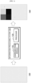
- FIG. 1 illustrates an example of an information processing system 100 performing a prediction work on a target image 130 according to an embodiment.
- the information processing system 100 may include a communication module 110 and a processor 120.
- the information processing system 100 may receive the target image 130 for prediction work through the communication module 110.
- the target image may refer to a whole slide image (WSI) that is an image captured with a microscope.
- the target image may include a pathology slide image or one or more patches included in the pathology slide image.
- the processor 120 may perform a prediction work on the received target image 130. Meanwhile, in order for the processor 120 to perform the prediction work using the target image 130 as it is, a high-capacity and high-cost memory and computational resource may be required. In addition, when the prediction work is performed by using the high-resolution target image 130 as it is, the operation speed of the processor 120 may be slowed. Under these conditions, the processor 120 may divide the target image 130 into a plurality of sub-images before performing the prediction work.
- the processor 120 may perform prediction works on a plurality of pixels included in each of the plurality of divided sub-images. For example, the processor 120 may determine a class for each of the plurality of pixels. In this case, the class may mean a target object such as cells, tissues, structures, etc. in the human body intended to be distinguished in the corresponding target image 130.
- the processor 120 may include a machine learning model for performing prediction work(s). For example, the processor 120 may input each of the plurality of divided sub-images to a segmentation machine learning model, and output a class for each of a plurality of pixels included in each of the plurality of sub-images.
- the processor 120 may merge all the prediction results for the plurality of pixels included in each of the plurality of sub-images, and output a final prediction result 140 for the target image 130.
- the prediction results at the boundary lines of the plurality of sub-images may not be smoothly connected. For example, when the prediction results of two sub-images in the vicinity of the boundary line are completely different from each other, the prediction results in the vicinity of the boundary line may appear to be severed.
- the processor 120 may divide the target image 130 into a plurality of sub-images, it may divide the sub-image such that each sub-image partially overlaps with another adjacent sub-image.
- the processor 120 may apply weights to certain regions where the prediction results of the plurality of sub-images overlap, and merge the weighted prediction results to generate a final prediction result for the target image.
- the processor 120 may calculate weights for generating and/or outputting a final prediction result 150 with prediction results for a plurality of sub-images having smooth boundaries in the target image.
- the processor 120 may set different weights according to positions of respective pixels of the plurality of sub-images.
- the processor 120 may apply bilinear weights to prediction results for pixels included in each of the plurality of sub-images.
- the weights may be set such that larger weights are applied to prediction results for pixels closer to the center in the plurality of sub-images than weights to be applied to prediction results for pixels closer to the edge in the plurality of sub-images.
- the processor 120 may determine that different weights are to be applied to at least some of the pixels of the plurality of sub-images, and that the same weight is to be applied to the remaining pixels.
- the weights determined as described above may be applied to prediction results for the plurality of sub-images.
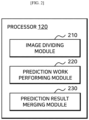
- FIG. 2 is a block diagram illustrating an internal configuration of the processor 120 according to an embodiment.
- the processor 120 may include an image dividing module 210, a prediction work performing module 220, and a prediction result merging module 230.
- the image dividing module 210 may divide the target image into a plurality of sub-images.
- the target image may be the whole slide image, and the sub-images may correspond to patches of the whole slide image.
- the image dividing module 210 may divide the target image such that a plurality of sub-images partially overlap with other adjacent sub-images.
- the image dividing module 210 may divide the image such that a portion of the first image included in the plurality of sub-images overlaps with a portion of the second image adjacent to the first image. Accordingly, when one sub-image is a rectangle, there is four adjacent sub-images, and the one sub-image may be divided to overlap with at least one sub-image among the four adjacent sub-images.
- the prediction work performing module 220 may perform a prediction work on a plurality of pixels included in each of the plurality of divided sub-images.
- the prediction work performing module 220 may determine a class for each of the plurality of pixels.
- the prediction work performing module 220 may input each of the plurality of divided sub-images to a segmentation machine learning model, and output a class for each of a plurality of pixels included in each of the plurality of sub-images.
- the class may be one of a plurality of classes representing a plurality of objects.
- the prediction work performing module 220 may generate a prediction result including the determined class. For example, the prediction work performing module 220 may use the class for each of the plurality of pixels to determine values for a plurality of channels corresponding to the plurality of classes. Additionally, the prediction work performing module 220 may generate a set (e.g., an array, etc.) corresponding to the prediction results for the plurality of pixels based on the determined values for the plurality of channels.
- the size of the generated array may be a value (w*h*c) obtained by multiplying the width (w) of each of the plurality of sub-images, the height (h) of each of the plurality of sub-images, and the size (c) of the plurality of channels.
- the prediction result merging module 230 may apply weights to the prediction results for a plurality of pixels.
- the prediction result merging module 230 may apply bilinear weights to prediction results for pixels included in each of the plurality of sub-images.
- the bilinear weights are weights used for bilinear interpolation applied to the prediction results for a plurality of pixels, and each of the bilinear weights may be calculated as values corresponding to each of the plurality of pixels.
- this bilinear weight may be calculated using Equation 1 below.
- the prediction result merging module 230 may apply a weight to each of the plurality of channels.
- the prediction result merging module 230 may merge the prediction results for the plurality of pixels applied with the weights.
- the prediction result merging module 230 may merge a prediction result applied with the weight corresponding to the pixel included in the overlapping portion of the first image, with a prediction result applied with the weight corresponding to the pixel included in the overlapping portion of the second image. That is, the prediction result merging module 230 may calculate a final prediction result by merging the weighted prediction result for each of sub-images in a partially overlapping manner.
- the prediction result merging module 230 may initialize an array for each of the final result and the final weight to zero (0) and generate a bilinear weight array. Then, the prediction result merging module 230 may add the result of multiplying the prediction result for each sub-image (e.g., patch) by the weight for each channel to the initialized final result array, and add the bilinear weights to the final weight array. That is, the prediction result merging module 230 may arrange the weighted prediction results for the plurality of sub-images according to positions of the plurality of sub-images in the target image, and merge the weighted prediction results.
- the prediction result merging module 230 may arrange the weighted prediction results for the plurality of sub-images according to positions of the plurality of sub-images in the target image, and merge the weighted prediction results.
- the prediction result merging module 230 may divide the value of each pixel in the final result array by the final weight value of the corresponding pixel in the final weight array to calculate the final prediction result.
- dividing by the final weight value may be done only when the final weight value is greater than zero, or dividing may be done by a value obtained by adding a very small number such as epsilon to the final weight value.
- the prediction result merging moldule 230 may calculate the final prediction result based on Equations 1 to 8 below.
- Equations 1 and 2 above may represent equations for determining bilinear weights to be applied to prediction results for sub-images.
- W w,h ( x,y ) in Equation 1 may mean a weight value for each pixel in a weight mask corresponding to each sub-image.
- the weight mask may refer to a set of weights to be applied to the pixels in the sub-image.
- w and h may represent a horizontal length and a vertical length of the mask, respectively.
- x may refer to one value in a range from 0 to w - 1
- y may refer to one value in a range from 0 to h - 1.
- ( x , y ) may represent one pixel in the weight mask.
- the weights to be applied to the prediction results for the pixels included in the region outside the weight mask, that is, W w,h ( x,y ) may be all defined as 0.
- the horizontal length and vertical length of the weight mask may be the same as the horizontal length and vertical length of the sub-image, respectively.
- the prediction result merging module 230 may sum the prediction results for the plurality of sub-images applied with the weights to calculate a value ( P ( x,y )) for each coordinate (each pixel).
- P ( x,y ) a value for each coordinate (each pixel).
- the prediction result merging module 230 may sum the weight masks for the sub-images to calculate a final weight value ( M ( x,y )) for each coordinate.
- F x y P x y M x y + ⁇
- the prediction result merging module 230 may calculate a final prediction result ( F ( x,y )) by dividing the calculated value P ( x,y ) for each coordinate by the final weight value M ( x,y ).
- ⁇ epsilon refers to a very small number, which may refer to a predetermined value, for example.
- FIG. 3 is a flowchart illustrating a method 300 for performing a prediction work on a target image according to an embodiment.
- the method 300 for performing a prediction work on a target image may be performed by a processor (e.g., at least one processor of the information processing system).
- the method 300 for performing the prediction work on the target image may be initiated by the processor by dividing the target image into a plurality of sub-images, at S310.
- the processor may divide the target image such that a portion of a first image included in the plurality of sub-images overlaps with a portion of a second image adjacent to the first image.
- each of the first image and the second image may be one or more sub-images.
- the processor may generate prediction results for a plurality of pixels included in each of the plurality of divided sub-images, at S320.
- the processor may determine a class for each of the plurality of pixels, and generate a prediction result including the determined class.
- the class may be one of a plurality of classes representing a plurality of objects.
- the processor may input each of the plurality of divided sub-images to the segmentation machine learning model to output a class for each of a plurality of pixels included in each of the plurality of sub-images.
- the processor may use the class for each of the plurality of pixels to determine values for a plurality of channels corresponding to the plurality of classes.
- the processor may generate an array corresponding to the prediction results for the plurality of pixels based on the determined values for the plurality of channels.
- the processor may apply weights to the prediction results for the generated plurality of pixels, at S330.
- the processor may apply bilinear weights to the prediction results for the pixels included in each of the plurality of sub-images.
- the bilinear weights may include a weight corresponding to each pixel calculated through bilinear interpolation.
- the processor may apply weights to each of the plurality of channels.
- the processor may merge the prediction results for the plurality of pixels applied with the weights, at S330.
- the processor may merge a prediction result applied with a first weight corresponding to the pixel included in the overlapping portion of the first image, with a prediction result applied with a second weight corresponding to the pixel included in the overlapping portion of the second image.
- FIG. 4 illustrates an example of performing a prediction work on a target image according to an embodiment.
- the processor may divide a target image 410 into a plurality of sub-images 420 to perform a prediction work on the target image 410.
- the processor may determine the size and/or the number of the plurality of sub-images 420 based on work speed, computational resource, memory, etc., and divide the target image 410 into a plurality of sub-images 420 based on the determined size and/or number of the sub-images 420.
- a plurality of sub-images 420 are illustrated as having the same size, but embodiments are not limited thereto, and the sizes of at least some images of the plurality of sub-images 420 may be different from each other.
- the processor may perform segmentation on each of the plurality of divided sub-images 420 to generate a plurality of prediction results 430 corresponding to the plurality of sub-images 420.
- the processor may determine a class for each of a plurality of pixels included in the plurality of sub-images, and generate a prediction result including the determined class.
- the class may be one of a plurality of classes representing a plurality of objects (e.g., each cell, tissue and/or structure, etc.).
- the prediction result for each sub-image is displayed using color, but embodiments are not limited thereto, and various methods for representing a class may be applied.
- the processor may use the class for each of the plurality of pixels to determine values for a plurality of channels corresponding to the plurality of classes.
- the processor may generate an array corresponding to the prediction results for the plurality of pixels based on the determined values for the plurality of channels.
- the prediction result 430 for each sub-image may have the number of the channels identical to the number of targeted classes. For example, when the processor performs segmentation for two classes of "cancer cells" and "lymphocytes" in the sub-image, the prediction result may have two channels.
- the processor may generate a final prediction result 440 for the target image by arranging and merging the prediction results 430 according to the respective positions of the plurality of sub-images 420 in the target image 410.
- the target image 410 may be a whole slide image that is an image captured with a microscope, and the whole slide image may be divided into a region in which tissue is placed on a glass slide (that is, tissue region as a target of the prediction work) and a region in which the tissue is not placed.
- the target image 410 may be a partial image corresponding to the tissue region in the whole slide image.
- the processor divides the target image 410 into the plurality of sub-images 420 such that the plurality of sub-images 420 cover the entire region of the target image 410, but embodiments are not limited thereto.
- the processor may divide the plurality of sub-images 420 to cover the tissue region that is a portion of the target image 410.
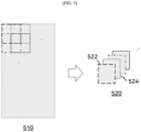
- FIG. 5 illustrates an example of a dividing a target image 510 into a plurality of sub-images 520 according to an embodiment.
- the processor may divide the sub-images such that each sub-image partially overlaps with another adjacent sub-image.
- the periphery of the sub-image has a narrower receptive field than the center and may have a lower performance of segmentation.
- the processor may divide the target image 510 such that the plurality of sub-images 520 have overlapping regions (that is, regions overlapping with adjacent sub-images), thereby improving the segmentation performance of the target image 510.
- the processor may divide the image such that a portion of a first image 522 that is a sub-image of the target image overlaps with a portion of a second image 524 that is another sub-image of the target image.
- the first image 522 and the second image 524 may be the sub-images adjacent to each other.
- four sub-images adjacent to each other including the first image 522 and the second image 524 may be divided to overlap with each other.
- the prediction performance of the processor may be improved.
- the processor may have to process the larger and/or more sub-images. Accordingly, the processor may determine the size of the region where the plurality of sub-images overlap with each other such that optimal prediction performance can be achieved, in consideration of work speed, computational resource, memory, prediction performance, etc.
- the processor may perform prediction works on a plurality of pixels included in each of the plurality of sub-images 520 divided as described above.
- FIG. 5 illustrates an example in which the target image 510 is divided into the plurality of sub-images 520 having the same size
- the target image 510 may be divided into a plurality of sub-images having different sizes
- the processor may divide the target image 510 such that each of the plurality of sub-images 520 has the same size overlapping regions as the other adjacent sub-images
- the processor may divide the target image 510 such that sizes of overlapping regions are different from each other.
- the target image 510 and the sub-image 520 are illustrated in the shape of quadrangles in FIG. 5
- embodiment is not limited thereto, and may have a different shape such as a polygon such as a triangle, a trapezoid, etc., a circle, or a curved shape, or the like.
- FIG. 6 illustrates an example of merging prediction results 610 for sub-images to generate a final prediction result 620 for a target image according to an embodiment.
- a prediction result of each of the plurality of sub-images may be indicated by color, but is not limited thereto, and may be indicated by any information that can represent the prediction result.
- the prediction result of each of the plurality of sub-images may be indicated by an RGB color, an one-dimensional black and white, a multi-dimensional image, etc.
- sky blue may represent a cancer epithelium class
- yellow may represent a lymphocyte cell class
- purple may represent a cancer stromal class
- indigo blue may represent a normal cell.
- the processor may apply weight masks to the prediction result 610 for each of the plurality of sub-images. That is, the processor may apply weights to the prediction results 610 for a plurality of pixels included in each of the plurality of sub-images.
- the processor may apply bilinear weights to the prediction results 610 for a plurality of pixels included in each of the plurality of sub-images.
- a bilinear weight is a weight corresponding to each pixel and may be calculated through bilinear interpolation.
- the processor may apply weights to each of the plurality of channels.
- the processor may generate the final prediction result 620 for the target image by arranging and merging the prediction result for each of the plurality of sub-images applied with weights according to the position of each of the plurality of sub-images in the target image.
- the processor may merge the prediction results for the plurality of pixels applied with the weights. For example, the processor may merge prediction results applied with weights corresponding to pixels included in the overlapping portion of the first image, with prediction results applied with weights corresponding to pixels included in the overlapping portion of the second image.
- the processor may merge the prediction result for each of the sub-images applied with the bilinear weights to output the final prediction result 620 having smooth boundaries as shown.
- each of the prediction results may be merged with the prediction result for other sub-images adjacent each other, in addition to the prediction results 610 illustrated as an example in FIG. 6 .
- the final prediction result 620 of FIG. 6 in certain region of the yellow prediction result, a color merged with the prediction result (not illustrated) for adjacent sub-image on the right side may be displayed.
- a color merged with the prediction result (not illustrated) for adjacent sub-image on the lower side may be displayed.
- a color merged with the prediction result (not illustrated) for adjacent sub-image on the right and the prediction result (not illustrated) for adjacent sub-image on the lower side may be displayed.
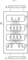
- FIG. 7 illustrates an example of an artificial neural network model 700 according to an embodiment.
- an artificial neural network model 700 as an example of the machine learning model refers to a statistical learning algorithm implemented based on a structure of a biological neural network, or to a structure that executes such algorithm.
- the artificial neural network 700 may represent a machine learning model that acquires a problem solving ability by repeatedly adjusting the weights of synapses by the nodes that are artificial neurons forming the network through synaptic combinations as in the biological neural networks, thus training to reduce errors between a target output corresponding to a specific input and a deduced output.
- the artificial neural network model 700 may include any probability model, neural network model, etc., that is used in an artificial intelligence learning method such as machine learning, deep learning, etc.
- the artificial neural network model 700 may include an artificial neural network model configured to receive a target image or a sub-image and output a class for each of the pixels in the image.
- the artificial neural network model 700 may include an artificial neural network model configured to receive a pathology slide image or at least one patch included in the pathology slide image and output a class for each of the pixels.
- the artificial neural network model 700 is implemented as a multilayer perceptron (MLP) formed of multiple nodes and connections between them.
- the artificial neural network model 700 may be implemented using one of various artificial neural network model structures including the MLP.
- the artificial neural network model 700 includes an input layer 720 to receive an input signal or data 710 from the outside, an output layer 740 to output an output signal or data 750 corresponding to the input data, and (n) number of hidden layers 730_1 to 730_n (where n is a positive integer) positioned between the input layer 720 and the output layer 740 for receiving a signal from the input layer 720, extract features, and transmit the features to the output layer 740.
- the output layer 740 receives signals from the hidden layers 730_1 to 730_n and outputs them to the outside.
- the method for training the artificial neural network model 700 includes a supervised learning method that trains to optimize for solving a problem with inputs of teacher signals (correct answers), and an unsupervised learning method that does not require a teacher signal.
- the information processing system may train the artificial neural network model 700 with the supervise learning method and/or the unsupervised learning such that class information for each of a plurality of pixels included in the target image and/or sub-images can be predicted.
- the artificial neural network model 700 trained as described above may be stored in a memory (not illustrated) of the information processing system, and, in response to an input of the target image or sub-image received from the communication module and/or memory, the artificial neural network model 700 may output the class information for each of a plurality of pixels included in the target image or sub-image.
- an input variable may be a pathology slide image or at least one patch included in the pathology slide image.
- the input variable input to the input layer 720 of the artificial neural network model 700 may be an image vector 710 including the pathology slide image or at least one patch included in the pathology slide image as one vector data element.
- the output variable output from the output layer 740 of the artificial neural network model 700 may be a vector 750 that represents or characterizes class information for each of a plurality of pixels included in at least the portion of the pathology slide image.
- the output layer 740 of the artificial neural network model 700 may be configured to output a vector representing a reliability and/or an accuracy of the output class information.
- the output variable of the artificial neural network model 700 is not limited to the types described above, and may include any information/data representing the class information.
- the input layer 720 and the output layer 740 of the artificial neural network model 700 are respectively matched with a plurality of output variables corresponding to a plurality of input variables, and the synaptic values between nodes included in the input layer 720, and the hidden layers 730_1 to 730_n, and the output layer 740 are adjusted, so that training can be processed to extract a correct output corresponding to a specific input.
- the features hidden in the input variables of the artificial neural network model 700 can be figured out, and the synaptic values (or weights) between the nodes of the artificial neural network model 700 can be adjusted so that there can be a reduced error between the target output and the output variable calculated based on the input variable.
- class information for a plurality of pixels included in the input image may be output in response to the input pathology slide image or at least one patch included in the pathology slide image.
- FIG. 8 illustrates an example of a target image and a sub-image, which are a pathology slide image and at least one patch included in the pathology slide image according to an embodiment.
- a pathology slide image 810 may refer to a digital image generated by capturing, through a microscope and a camera, a pathology slide stained and/or fixed through a series of chemical treatments of at least a portion of the tissue obtained from the human body.
- the pathology slide image 810 may be stained by hematoxylin and eosin (H&E) staining technique, but is not limited thereto, and may include an image generated by capturing, through a microscope and a camera, a pathology slide stained with already known different staining technique(s).
- H&E hematoxylin and eosin
- the target image according to embodiments of the present disclosure may be a pathology slide image 810, and the sub-image may be a patch 820 included in the pathology slide image 810.
- the target image according to embodiments of the present disclosure may be the patch 820 included in the pathology slide image 810, and the sub-image may be a patch 830 of a smaller unit than the target image, i.e., the patch 820.
- the sub-image, that is, the patch 830 of a small unit may be included in the target image, that is, the patch 820.
- the processor may input the pathology slide image 810 and/or the patches 820 and 830 into a machine learning model to perform a prediction work on the pathology slide image 810 and/or the patches 820 and 830, and generate prediction results.
- the processor may input the pathology slide image 810 and/or the patches 820 and 830 into the machine learning model and output a plurality of class for the plurality pixels included in the pathology slide images 810 and/or the patches 820 and 830.
- the machine learning model may be a segmentation machine learning model (e.g., the artificial neural network model 700 of FIG. 7 ) trained to receive an image as an input and output a class for each of a plurality of pixels included in the image.
- various segmentation algorithms may be applied to the segmentation machine learning model, which may be a semantic segmentation machine learning model and/or an instance segmentation machine learning model, for example.
- class information for at least some of the plurality of pixels included in the pathology slide image 810 and/or the patches 820 and 830 may be tagged and/or indicated.
- the first region of the pathology slide image 810 may indicate the class information of cancer stroma
- the second region may indicate class information of cancer epithelium.
- the first region corresponding to the cancer stromal region may be colored purple
- the second region corresponding to the cancer epithelium region may be colored sky blue.
- the class information may be expressed in various visual indications such as region indications, shape indications, other color indications, text, or the like.
- the pathology slide image 810 may be provided to the processor as a target image in a compressed form of an original image, captured with microscope, and upon segmentation of the compressed image into a plurality of patches 820 as a plurality of sub-images, decompressed images corresponding to the plurality of patches 820 may be provided to the processor. Likewise, an enlarged image of the patch 830 of a small unit included in the patch 820 may be acquired. In FIG. 2 , the images corresponding to the patch 820 and the patch 830 of a smaller unit are each enlarged at a specific magnification, but embodiments are not limited thereto, and the pathology slide image and/or the image corresponding to the patches included therein may be enlarged or reduced at various magnifications.
- FIG. 9 illustrates an example of a prediction result for a target image, generated by merging the prediction results for two sub-images according to some embodiments.
- the processor may divide the target image into a first sub-image and a second sub-image, and perform a prediction work on each of the divided first sub-image and second sub-image. That is, the prediction work may be performed on a plurality of pixels included in each of the first sub-image and the second sub-image. Then, the processor may generate prediction result for the target image by merging the prediction results for the first sub-image and the second sub-image.
- a first prediction result 910 represents a result of dividing the target image in a way such that the first sub-image and the second sub-image do not overlap with each other, and simply arranging and merging the prediction results of the first sub-image and the second sub-image without overlap.
- the prediction results are not smoothly connected in the vicinity of the boundary between the first sub-image and the second sub-image. That is, in certain region of the final prediction result 910 generated by merging the prediction results of each of the sub-images without overlapping regions, the resultant prediction appears as if it has discontinuity.
- a clear boundary may appear between the red prediction result and the blue prediction result.
- it may be difficult to guarantee the accuracy of the prediction result in the vicinity of the boundary between the first sub-image and the second sub-image.
- a second prediction result 920 represents a result of dividing the first sub-image and the second sub-image overlappingly with each other, and merging calculating an overlapping region between the prediction result of the first sub-image and the prediction result of the second sub-image as average values of the prediction result of the first sub-image and the prediction result of the second sub-image.
- artifact may occur, in which the prediction results appear as if they are discontinued at the boundary lines where the sub-images overlap with each other.
- a region where the red prediction result and the blue prediction result overlap with each other represents purple which is an intermediate value. Accordingly, the boundary between red and purple and the boundary between purple and blue being clearly distinguishable, n consideration of the human cell and/or histological formation it may be difficult to guarantee the accuracy of the second prediction result 920.
- a third prediction result 930 represents a result of dividing the first sub-image and the second sub-image overlappingly with each other, and merging applying different weights (e.g., linear weights) to the prediction results for the plurality of pixels included in the first sub-image and the prediction results for the plurality of pixels included in the second sub-image.
- weights e.g., linear weights
- the prediction result for the target image is generated by merging the prediction results for two sub-images, but embodiments are not limited thereto, and the final prediction result for the target image may be generated by merging prediction results for a plurality of sub-images, including three or more sub-images.
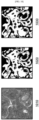
- FIG. 10 illustrates an example of prediction results 1020 and 1030 for a pathology slide image 1010 generated by merging prediction results for a plurality of patches according to embodiments of the present disclosure.
- the processor may divide the pathology slide image 1010 into a plurality of patches, and perform a prediction work on a plurality of pixels included in each of the plurality of divided patches. In this case, each of the plurality of divided patches may partially overlap with adjacent patches. Then, the processor may apply weights to the prediction results for a plurality of pixels included in each of the plurality of patches, merge the prediction results for the plurality of pixels applied with the weights, and generate a prediction result for the pathology slide image 1010.
- the first prediction result 1020 may show a result of applying an average weight to the prediction results for the plurality of pixels included in each of the plurality of patches, and merging the prediction results for the plurality of pixels applied with the average weight. That is, the processor may calculate the prediction results of the overlapping region of the plurality of patches as the average values of the prediction results for the overlapping pixels. As shown in the red dotted line box region of the first prediction result 1020, the boundary lines of the patch may be clearly revealed, and the artifact of discontinuity in the prediction results may appear. Accordingly, when considering human cells and/or histological formation, it may be difficult to guarantee the accuracy of the first prediction result 1020.
- the second prediction result 1030 may show a result of applying bilinear weights to the prediction results for a plurality of pixels included in each of the plurality of patches, and merging the prediction results for the plurality of pixels applied with the bilinear weights.
- the second prediction result 1030 it can be confirmed that the artifact of discontinuity in the result does not occur between the prediction results of the plurality of patches.
- the method for merging the prediction results for patches by applying the bilinear weight to the prediction results can improve the accuracy of the prediction result for the pathology slide image 1010, more than that of the method for merging by applying the average weight.
- the prediction results 1020 and 1030 for the pathology slide image 1010 are illustrated as black and white images, but embodiments are not limited thereto.
- the prediction result for the pathology slide image may be displayed as RGB color and/or a multidimensional image, etc.
- FIG. 11 illustrates a configuration of an exemplary system for performing a prediction work on a target image according to an embodiment.
- the information processing system 100 may include one or more processors 1110, a bus 1130, a communication interface 1140, a memory 1120 for loading a computer program 1160 to be executed by the processors 1110, and a storage module 1150 for storing the computer program 1160.
- processors 1110 may include one or more processors 1110, a bus 1130, a communication interface 1140, a memory 1120 for loading a computer program 1160 to be executed by the processors 1110, and a storage module 1150 for storing the computer program 1160.
- FIG. 11 illustrates a configuration of an exemplary system for performing a prediction work on a target image according to an embodiment.
- the information processing system 100 may include one or more processors 1110, a bus 1130, a communication interface 1140, a memory 1120 for loading a computer program 1160 to be executed by the processors 1110, and a storage
- the processors 1110 control the overall operation of components of the information processing system 100.
- the processors 1110 may be configured to include a central processing unit (CPU), a micro processor unit (MPU), a micro controller unit (MCU), a graphic processing unit (GPU), or any type of processor well known in the technical field of the present disclosure.
- the processors 1110 may perform an arithmetic operation on at least one application or program for executing the method according to the embodiments of the present disclosure.
- the information processing system 100 may include one or more processors.
- the memory 1120 may store various types of data, commands, and/or information.
- the memory 1120 may load one or more computer programs 1160 from the storage module 1150 in order to execute the method/operation according to various embodiments of the present disclosure.
- the memory 1120 may be implemented as a volatile memory such as RAM, although the technical scope of the present disclosure is not limited thereto.
- the bus 1130 may provide a communication function between components of the information processing system 100.
- the bus 1130 may be implemented as various types of buses such as an address bus, a data bus, a control bus, etc.
- the communication interface 1140 may support wired/wireless Internet communication of the information processing system 100.
- the communication interface 1140 may support various other communication methods in addition to the Internet communication.
- the communication interface 1140 may be configured to include a communication module well known in the technical field of the present disclosure.
- the storage module 1150 may non-temporarily store one or more computer programs 1160.
- the storage module 1150 may be configured to include a nonvolatile memory such as a read only memory (ROM), an erasable programmable ROM (EPROM), an electrically erasable programmable ROM (EEPROM), a flash memory, etc., a hard disk, a detachable disk, or any type of computer-readable recording medium well known in the art to which the present disclosure pertains.
- ROM read only memory
- EPROM erasable programmable ROM
- EEPROM electrically erasable programmable ROM
- flash memory etc.
- hard disk a hard disk
- detachable disk or any type of computer-readable recording medium well known in the art to which the present disclosure pertains.
- the computer program 1160 may include one or more instructions that, when loaded into the memory 1120, cause the processors 1110 to perform an operation/method in accordance with various embodiments of the present disclosure. That is, the processors 1110 may perform operations/methods according to various embodiments of the present disclosure by executing one or more instructions.
- the computer program 1160 may include one or more instructions to perform operations of dividing a target image into a plurality of sub-images, generating prediction results for a plurality of pixels included in each of the plurality of divided sub-images, applying weights to the prediction results for the plurality of pixels, and merging the prediction results for the plurality of pixels applied with the weights.
- the system for performing a prediction work on a target image may be implemented through the information processing system 100.
- example implementations may refer to utilizing aspects of the presently disclosed subject matter in the context of one or more standalone computer systems, the subject matter is not so limited, and they may be implemented in conjunction with any computing environment, such as a network or distributed computing environment. Furthermore, aspects of the presently disclosed subject matter may be implemented in or across a plurality of processing chips or devices, and storage may be similarly influenced across a plurality of devices. Such devices may include PCs, network servers, and handheld devices.
Landscapes
- Engineering & Computer Science (AREA)
- Theoretical Computer Science (AREA)
- Physics & Mathematics (AREA)
- General Physics & Mathematics (AREA)
- Computer Vision & Pattern Recognition (AREA)
- Evolutionary Computation (AREA)
- Data Mining & Analysis (AREA)
- Artificial Intelligence (AREA)
- General Engineering & Computer Science (AREA)
- Computing Systems (AREA)
- Software Systems (AREA)
- Multimedia (AREA)
- General Health & Medical Sciences (AREA)
- Health & Medical Sciences (AREA)
- Life Sciences & Earth Sciences (AREA)
- Medical Informatics (AREA)
- Computational Linguistics (AREA)
- Mathematical Physics (AREA)
- Evolutionary Biology (AREA)
- Bioinformatics & Computational Biology (AREA)
- Bioinformatics & Cheminformatics (AREA)
- Databases & Information Systems (AREA)
- Probability & Statistics with Applications (AREA)
- Biomedical Technology (AREA)
- Molecular Biology (AREA)
- Nuclear Medicine, Radiotherapy & Molecular Imaging (AREA)
- Radiology & Medical Imaging (AREA)
- Quality & Reliability (AREA)
- Image Processing (AREA)
Applications Claiming Priority (2)
| Application Number | Priority Date | Filing Date | Title |
|---|---|---|---|
| KR1020200144411A KR102429534B1 (ko) | 2020-11-02 | 2020-11-02 | 대상 이미지에 대한 추론 작업을 수행하는 방법 및 시스템 |
| PCT/KR2021/015734 WO2022092993A1 (ko) | 2020-11-02 | 2021-11-02 | 대상 이미지에 대한 추론 작업을 수행하는 방법 및 시스템 |
Publications (2)
| Publication Number | Publication Date |
|---|---|
| EP4239533A1 true EP4239533A1 (de) | 2023-09-06 |
| EP4239533A4 EP4239533A4 (de) | 2024-10-02 |
Family
ID=81383025
Family Applications (1)
| Application Number | Title | Priority Date | Filing Date |
|---|---|---|---|
| EP21802585.6A Pending EP4239533A4 (de) | 2020-11-02 | 2021-11-02 | Verfahren und system zur durchführung einer vorhersageoperation auf einem zielbild |
Country Status (4)
| Country | Link |
|---|---|
| US (2) | US12450315B2 (de) |
| EP (1) | EP4239533A4 (de) |
| KR (2) | KR102429534B1 (de) |
| WO (1) | WO2022092993A1 (de) |
Families Citing this family (3)
| Publication number | Priority date | Publication date | Assignee | Title |
|---|---|---|---|---|
| KR102572423B1 (ko) * | 2023-03-07 | 2023-08-30 | 주식회사 에이모 | 인스턴스 레이어를 생성하는 방법 및 장치 |
| KR102563550B1 (ko) | 2023-04-14 | 2023-08-11 | 고려대학교산학협력단 | 읽기 전용 프롬프트 학습 방법 및 장치 |
| KR20250131924A (ko) | 2024-02-27 | 2025-09-04 | 씨제이올리브네트웍스 주식회사 | 영상과 대본 파일을 이용하여 자연어 기반의 학습 데이터를 생성하고, 학습 데이터를 이용하여 이미지 생성 및 추론을 수행하는 방법 및 장치 |
Family Cites Families (15)
| Publication number | Priority date | Publication date | Assignee | Title |
|---|---|---|---|---|
| KR101400410B1 (ko) * | 2012-08-14 | 2014-05-28 | 이화여자대학교 산학협력단 | 현미경 영상 내 세포 분류 방법 및 장치 |
| US10055551B2 (en) * | 2013-10-10 | 2018-08-21 | Board Of Regents Of The University Of Texas System | Systems and methods for quantitative analysis of histopathology images using multiclassifier ensemble schemes |
| CN105608459B (zh) * | 2014-10-29 | 2018-09-14 | 阿里巴巴集团控股有限公司 | 商品图片的分割方法及其装置 |
| US10223788B2 (en) * | 2016-08-31 | 2019-03-05 | International Business Machines Corporation | Skin lesion segmentation using deep convolution networks guided by local unsupervised learning |
| US20180137391A1 (en) * | 2016-11-13 | 2018-05-17 | Imagry (Israel) Ltd. | System and method for training image classifier |
| US10754035B2 (en) * | 2017-01-17 | 2020-08-25 | Aptiv Technologies Limited | Ground classifier system for automated vehicles |
| KR102481885B1 (ko) * | 2017-09-08 | 2022-12-28 | 삼성전자주식회사 | 클래스 인식을 위한 뉴럴 네트워크 학습 방법 및 디바이스 |
| KR101973322B1 (ko) * | 2017-12-13 | 2019-04-30 | 건국대학교 산학협력단 | 영상 레이블 추론 방법 및 이를 수행하는 장치들 |
| US10957041B2 (en) * | 2018-05-14 | 2021-03-23 | Tempus Labs, Inc. | Determining biomarkers from histopathology slide images |
| KR102811789B1 (ko) * | 2018-09-19 | 2025-05-27 | 엘지전자 주식회사 | 인공지능 장치 |
| US10783632B2 (en) * | 2018-12-14 | 2020-09-22 | Spectral Md, Inc. | Machine learning systems and method for assessment, healing prediction, and treatment of wounds |
| US10929665B2 (en) * | 2018-12-21 | 2021-02-23 | Samsung Electronics Co., Ltd. | System and method for providing dominant scene classification by semantic segmentation |
| US11676685B2 (en) * | 2019-03-21 | 2023-06-13 | Illumina, Inc. | Artificial intelligence-based quality scoring |
| US11645756B2 (en) * | 2019-11-14 | 2023-05-09 | Samsung Electronics Co., Ltd. | Image processing apparatus and method |
| CN111369512A (zh) * | 2020-02-28 | 2020-07-03 | 上海商汤智能科技有限公司 | 图像处理方法及装置、电子设备和存储介质 |
-
2020
- 2020-11-02 KR KR1020200144411A patent/KR102429534B1/ko active Active
-
2021
- 2021-11-02 WO PCT/KR2021/015734 patent/WO2022092993A1/ko not_active Ceased
- 2021-11-02 EP EP21802585.6A patent/EP4239533A4/de active Pending
-
2022
- 2022-02-15 US US17/671,936 patent/US12450315B2/en active Active
- 2022-08-01 KR KR1020220095389A patent/KR102902810B1/ko active Active
-
2025
- 2025-09-30 US US19/345,677 patent/US20260023822A1/en active Pending
Also Published As
| Publication number | Publication date |
|---|---|
| EP4239533A4 (de) | 2024-10-02 |
| KR102902810B1 (ko) | 2025-12-22 |
| US12450315B2 (en) | 2025-10-21 |
| US20220172009A1 (en) | 2022-06-02 |
| KR20220113891A (ko) | 2022-08-17 |
| US20260023822A1 (en) | 2026-01-22 |
| KR102429534B1 (ko) | 2022-08-04 |
| KR20220059155A (ko) | 2022-05-10 |
| WO2022092993A1 (ko) | 2022-05-05 |
Similar Documents
| Publication | Publication Date | Title |
|---|---|---|
| US20260023822A1 (en) | Method and system for performing prediction work on target image | |
| Weigert et al. | Star-convex polyhedra for 3D object detection and segmentation in microscopy | |
| CN111310775B (zh) | 数据训练方法、装置、终端设备及计算机可读存储介质 | |
| CN110378297B (zh) | 基于深度学习的遥感图像目标检测方法、装置、及存储介质 | |
| CN111985458B (zh) | 一种检测多目标的方法、电子设备及存储介质 | |
| US12198381B2 (en) | Hand pose estimation method, device and storage medium | |
| US11710552B2 (en) | Method and system for refining label information | |
| US10121245B2 (en) | Identification of inflammation in tissue images | |
| CN110516541B (zh) | 文本定位方法、装置、计算机可读存储介质和计算机设备 | |
| KR102580419B1 (ko) | 병리 슬라이드 이미지 내의 관심 영역을 검출하기 위한 방법 및 시스템 | |
| CN113887455B (zh) | 一种基于改进fcos的人脸口罩检测系统及方法 | |
| CN111008561A (zh) | 一种牲畜的数量确定方法、终端及计算机存储介质 | |
| US20220261988A1 (en) | Method and system for detecting region of interest in pathological slide image | |
| EP4293631A1 (de) | Verfahren und vorrichtung zur bildgruppierung, computervorrichtung und speichermedium | |
| US20230419492A1 (en) | Method and apparatus for providing information associated with immune phenotypes for pathology slide image | |
| CN112733873A (zh) | 一种基于深度学习的染色体核型图分类方法及装置 | |
| EP3998586A1 (de) | Verfahren und system zur vorhersage des ansprechens auf eine therapie bei krebskranken | |
| CN113269752A (zh) | 一种图像检测方法、装置终端设备及存储介质 | |
| CN114663743B (zh) | 一种船舶目标重识别方法、终端设备及存储介质 | |
| CN115311542B (zh) | 一种目标检测方法、装置、设备和介质 | |
| Singh et al. | Adversarially Enhanced Learning (AEL): Robust lightweight deep learning approach for radiology image classification against adversarial attacks | |
| Hassan et al. | Automatic ovarian follicle detection using object detection models | |
| CN120198409A (zh) | 一种基于改进YOLOv8的血细胞检测方法 | |
| US20220092448A1 (en) | Method and system for providing annotation information for target data through hint-based machine learning model | |
| US12488893B2 (en) | Method and system for training machine learning model for detecting abnormal region in pathological slide image |
Legal Events
| Date | Code | Title | Description |
|---|---|---|---|
| STAA | Information on the status of an ep patent application or granted ep patent |
Free format text: STATUS: UNKNOWN |
|
| STAA | Information on the status of an ep patent application or granted ep patent |
Free format text: STATUS: THE INTERNATIONAL PUBLICATION HAS BEEN MADE |
|
| PUAI | Public reference made under article 153(3) epc to a published international application that has entered the european phase |
Free format text: ORIGINAL CODE: 0009012 |
|
| STAA | Information on the status of an ep patent application or granted ep patent |
Free format text: STATUS: REQUEST FOR EXAMINATION WAS MADE |
|
| 17P | Request for examination filed |
Effective date: 20211119 |
|
| AK | Designated contracting states |
Kind code of ref document: A1 Designated state(s): AL AT BE BG CH CY CZ DE DK EE ES FI FR GB GR HR HU IE IS IT LI LT LU LV MC MK MT NL NO PL PT RO RS SE SI SK SM TR |
|
| DAV | Request for validation of the european patent (deleted) | ||
| DAX | Request for extension of the european patent (deleted) | ||
| REG | Reference to a national code |
Ref country code: DE Ref legal event code: R079 Free format text: PREVIOUS MAIN CLASS: G06N0005040000 Ipc: G06T0007000000 |
|
| A4 | Supplementary search report drawn up and despatched |
Effective date: 20240904 |
|
| RIC1 | Information provided on ipc code assigned before grant |
Ipc: G06V 20/69 20220101ALI20240829BHEP Ipc: G06V 10/82 20220101ALI20240829BHEP Ipc: G06V 10/80 20220101ALI20240829BHEP Ipc: G06V 10/26 20220101ALI20240829BHEP Ipc: G06N 5/04 20230101ALI20240829BHEP Ipc: G06T 7/00 20170101AFI20240829BHEP |
|
| STAA | Information on the status of an ep patent application or granted ep patent |
Free format text: STATUS: EXAMINATION IS IN PROGRESS |
|
| 17Q | First examination report despatched |
Effective date: 20251118 |