EP4239300B1 - Verteilte einband-temperaturmessung - Google Patents
Verteilte einband-temperaturmessung Download PDFInfo
- Publication number
- EP4239300B1 EP4239300B1 EP23183139.7A EP23183139A EP4239300B1 EP 4239300 B1 EP4239300 B1 EP 4239300B1 EP 23183139 A EP23183139 A EP 23183139A EP 4239300 B1 EP4239300 B1 EP 4239300B1
- Authority
- EP
- European Patent Office
- Prior art keywords
- dut
- stokes
- laser beam
- laser
- traces
- Prior art date
- Legal status (The legal status is an assumption and is not a legal conclusion. Google has not performed a legal analysis and makes no representation as to the accuracy of the status listed.)
- Active
Links
Images


Classifications
-
- G—PHYSICS
- G01—MEASURING; TESTING
- G01K—MEASURING TEMPERATURE; MEASURING QUANTITY OF HEAT; THERMALLY-SENSITIVE ELEMENTS NOT OTHERWISE PROVIDED FOR
- G01K11/00—Measuring temperature based upon physical or chemical changes not covered by groups G01K3/00, G01K5/00, G01K7/00 or G01K9/00
- G01K11/32—Measuring temperature based upon physical or chemical changes not covered by groups G01K3/00, G01K5/00, G01K7/00 or G01K9/00 using changes in transmittance, scattering or luminescence in optical fibres
-
- G—PHYSICS
- G01—MEASURING; TESTING
- G01K—MEASURING TEMPERATURE; MEASURING QUANTITY OF HEAT; THERMALLY-SENSITIVE ELEMENTS NOT OTHERWISE PROVIDED FOR
- G01K1/00—Details of thermometers not specially adapted for particular types of thermometer
- G01K1/02—Means for indicating or recording specially adapted for thermometers
- G01K1/024—Means for indicating or recording specially adapted for thermometers for remote indication
-
- G—PHYSICS
- G01—MEASURING; TESTING
- G01K—MEASURING TEMPERATURE; MEASURING QUANTITY OF HEAT; THERMALLY-SENSITIVE ELEMENTS NOT OTHERWISE PROVIDED FOR
- G01K13/00—Thermometers specially adapted for specific purposes
- G01K13/20—Clinical contact thermometers for use with humans or animals
- G01K13/223—Infrared clinical thermometers, e.g. tympanic
-
- G—PHYSICS
- G01—MEASURING; TESTING
- G01K—MEASURING TEMPERATURE; MEASURING QUANTITY OF HEAT; THERMALLY-SENSITIVE ELEMENTS NOT OTHERWISE PROVIDED FOR
- G01K3/00—Thermometers giving results other than momentary value of temperature
- G01K3/02—Thermometers giving results other than momentary value of temperature giving means values; giving integrated values
- G01K3/06—Thermometers giving results other than momentary value of temperature giving means values; giving integrated values in respect of space
-
- G—PHYSICS
- G01—MEASURING; TESTING
- G01K—MEASURING TEMPERATURE; MEASURING QUANTITY OF HEAT; THERMALLY-SENSITIVE ELEMENTS NOT OTHERWISE PROVIDED FOR
- G01K11/00—Measuring temperature based upon physical or chemical changes not covered by groups G01K3/00, G01K5/00, G01K7/00 or G01K9/00
- G01K11/32—Measuring temperature based upon physical or chemical changes not covered by groups G01K3/00, G01K5/00, G01K7/00 or G01K9/00 using changes in transmittance, scattering or luminescence in optical fibres
- G01K11/324—Measuring temperature based upon physical or chemical changes not covered by groups G01K3/00, G01K5/00, G01K7/00 or G01K9/00 using changes in transmittance, scattering or luminescence in optical fibres using Raman scattering
Definitions
- Distributed temperature sensing may be described as the measurement of temperature by using optical fibers.
- an optical fiber may function as a sensor.
- a distributed temperature sensing system may provide temperature measurements at specified distances along the length of the optical fiber.
- the specified distances may include a spatial resolution of one meter.
- the temperature measurements may be made to a specified accuracy (e.g., ⁇ 0.5°C).
- WO2009/011766 discloses dual source auto-correction in distributed temperature systems.
- WO2009092436 discloses distributed temperature sensing using two wavelengths differing by a Raman shift of a waveguide.
- the terms “a” and “an” are intended to denote at least one of a particular element.
- the term “includes” means includes but not limited to, the term “including” means including but not limited to.
- the term “based on” means based at least in part on.
- OTDR OT-ray tracing spectroscopy
- Other types of features that may be measured by the OTDR include temperature distribution along a fiber, attenuation uniformity and attenuation rate, segment length, and location and insertion loss of connectors, splices, or any other optical components such as splitters or multiplexers.
- an OTDR may include distributed temperature sensing (DTS).
- DTS distributed temperature sensing
- Raman distributed temperature sensing may encounter different attenuations at different test wavelengths.
- the different test wavelengths may include the Anti-Stokes (AS) wavelength, the Rayleigh wavelength, the Stokes wavelength, etc.
- AS Anti-Stokes
- interrogation of an optical fiber may be performed by using several laser sources. Alternatively or additionally, the interrogation of the optical fiber may be dual-ended (e.g., on both ends of the optical fiber).
- the distributed temperature sensing results may include inconsistencies in that differing spectral shapes of the various test signals used may result in different mean-weighted-average wavelengths and non-matching attenuation compensations.
- the need to access both ends of an optical fiber may add additional technical complexities, for example, with respect to a downhole end of the optical fiber.
- Distributed temperature sensing utilizes the temperature sensitivity of an anti-Stokes Raman band in order to derive temperature. Since the transient Raman OTDR signal may also decay with attenuation, the signal may be normalized to the Stokes-OTDR trace. In this regard, a Rayleigh OTDR trace may also be utilized.
- a temperature distribution sensor as disclosed herein may utilize two spectral slices of the Anti-Stokes Raman to implement distributed temperature sensing.
- the coefficient of the Anti-Stokes power variation versus temperature depends on the exact wavelength. As disclosed herein, this dependency may be evident from the literal equation of the anti-Stokes power derived from Bose-Einstein statistics.
- the differential response at closely spaced wavelengths may be utilized as a new mechanism in distributed temperature sensing, with an inherently reduced differential loss, while also offering new means for differential losses compensation.
- FIG 1 illustrates an architecture of a temperature distribution sensor 100 (hereinafter referred to as "sensor 100").
- the senor 100 which is an OTDR, includes a laser source 102 to emit a laser beam that is tunable over a wavelength range.
- the wavelength range is less than a Raman bandwidth in a device under test (DUT) 104, or of-the-order-of the Raman bandwidth in the DUT 104.
- the DUT 104 may include an optical fiber.
- a pulsed source 106 applies a pulse drive signal to the laser beam or to a modulator to modulate the laser beam that is to be injected into the DUT 104.
- a bandpass filter 108 is operatively disposed between the laser source 102 and the DUT 104.
- the bandpass filter 108 is configured to an anti-Stokes wavelength that is narrower than the Raman bandwidth.
- a photodiode 110 may be operatively disposed between the bandpass filter 108 and the DUT 104 to acquire, from the DUT 104, anti-Stokes optical time-domain reflectometer traces for two preset wavelengths of the laser beam to determine (e.g., by a sensor controller) a temperature distribution 112 for the DUT 104.
- the temperature distribution 112 for the DUT 104 may be determined by determining a ratio of the anti-Stokes optical time-domain reflectometer traces for the two preset wavelengths of the laser beam.
- a wavelength difference resulting from differing anti-Stokes spectral slices and a corresponding mean weighted average wavelength may be corrected.
- a further photodiode 114 may be operatively disposed between the laser source 102 and the bandpass filter 108 to acquire Rayleigh optical time-domain reflectometer traces at the two preset wavelengths of the laser beam.
- a differential attenuation between the two preset wavelengths of the laser beam may be corrected by determining a ratio of the Rayleigh optical time-domain reflectometer traces at the two preset wavelengths of the laser beam.
- a fiber amplifier 116 may amplify the pulse drive signal applied to the laser beam or to the modulator to modulate the laser beam that is to be injected into the DUT 104.
- the amplifier 116 may comprise a temporal gating element that may suppress the amplified spontaneous emission and associated power fluctuations in between pulses.
- the sensor 100 may be operated, using the narrow linewidth tunable laser source, in a Rayleigh mode to record a distributed acoustic sensing signal over the DUT 104.
- the senor 200 which may be an OTDR, may include a first laser source 202 to emit a first laser beam, and a second laser source 204 to emit a second laser beam.
- the first and second laser beams may include wavelengths that differ by a quantity that is less than a Raman bandwidth in a DUT 206, or of-the-order-of the Raman bandwidth in the DUT 206.
- a pulsed source 208 may apply a pulse drive signal to the first and second laser beams or to a modulator to modulate the first and second laser beams that are to be injected into the DUT 206.
- a bandpass filter 210 may be operatively disposed between the first laser source 202 and the second laser source 204 and the DUT 206.
- the bandpass filter 210 may be configured to an anti-Stokes wavelength that is narrower than the Raman bandwidth.
- a photodiode 212 may be operatively disposed between the bandpass filter 210 and the DUT 206 to acquire, from the DUT 206, anti-Stokes optical time-domain reflectometer traces for two preset wavelengths of the first and second laser beams to determine a temperature distribution 214 for the DUT 206.
- the photodiode 212 may be connected to the passing port of the bandpass filter 210.
- the first laser source 202 and the second laser source 204 may be connected to the reflective port of the bandpass filter 210 (complementary of the passband function), and the DUT 206 to the common port of the bandpass filter 210.
- a further photodiode 216 may be operatively disposed between the first laser source 202 and the second laser source 204 and the bandpass filter 210 to acquire Rayleigh optical time-domain reflectometer traces at the two pre-set wavelengths of the first and second laser beams.
- the sensor 100 may utilize two spectral slices of the Anti-Stokes Raman to implement distributed temperature sensing.
- the coefficient of the Anti-Stokes power variation versus temperature may depend on the exact wavelength. This dependency may be evident from the literal expression of the number of optical phonons ⁇ generated by thermal agitation and derived from Bose-Einstein statistics.
- ⁇ ⁇ T 1 exp h ⁇ kT ⁇ 1 Equation (1) represents the number of optical phonons generated by thermal agitation at frequency ⁇ , k represents the Boltzmann constant, and T represents the temperature of the DUT.
- the anti-Stokes power for each spectral component is directly proportional to this number of phonons.
- a single mean-weighted-average Raman frequency shift of about 13.2THz may be retained. The same considerations may apply to the Stokes component.
- Equation (2) Calculations based on a mean wavelength may result in the following relationship between temperature and Anti-Stokes/Stokes ratio:
- R z T ⁇ S ⁇ AS 4 exp ⁇ h ⁇ ⁇ kT z exp ⁇ ⁇ 0 z ⁇ AS ⁇ ⁇ ⁇ S ⁇ d ⁇ ,
- Equation (2) may account for the potentially different losses at the Stokes and anti-Stokes wavelengths.
- Equation (2) R represents the power ratio of anti-Stokes and Stokes, z represents the position along the DUT, T represents the temperature, ⁇ S represents the mean-weighted average wavelength of the Stokes profile, ⁇ AS represents the mean-weighted average wavelength of the anti-Stokes profile, h represents the Planck's constant , k represents the Boltzmann constant, ⁇ AS represents the DUT attenuation coefficient at ⁇ AS , ⁇ S represents the DUT attenuation coefficient at ⁇ AS , ⁇ represents the position in the integral, and d ⁇ represents an increment on position in the integral
- the spectral dependency of the phonon population within a single Raman anti-Stokes band may be utilized as the core mechanism for sensing.
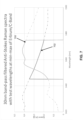
- Figure 3 illustrates the sensitivity as a function of wavelength, when the DUT is illuminated at 1550nm, according to an example of the present disclosure.
- the sensitivity may vary substantially across the useful range of the Raman profile. The mean value of 0.8%/K may be found at Raman resonance of 1450nm, but sensitivity may vary from 0.95 to 0.72%/K for spectral components of 1430 to 1470nm respectively.
- a 0.23%/K sensitivity may be expected. This lower sensitivity value may increase the sensitivity to detection noises and lower the dynamic range.
- a reduced spectral range e.g., 40nm instead of 200nm at 1550nm.
- Figures 4-6 illustrate examples of implementation of the temperature distribution sensors of Figures 1 and 2 .
- an implementation 400 of the sensor 100 includes the laser source 102 (or the first laser source 202 and the second laser source 204) at section 402 of the sensor 100.
- the bandpass filter 108 (or the bandpass filter 210) are operatively disposed between the laser source 102 and the DUT 104, and are configured to an anti-Stokes wavelength that is narrower than the Raman bandwidth.
- the photodiode 110 (or the photodiode 212), designated as an avalanche photodiode (APD), may be operatively disposed between the bandpass filter 108 and the DUT 104 to acquire, from the DUT 104, anti-Stokes optical time-domain reflectometer traces for two preset wavelengths of the laser beam to determine the temperature distribution 112 for the DUT 104.
- the further photodiode 114 (or the further photodiode 216) may be operatively disposed between the laser source 102 and the bandpass filter 108 to acquire Rayleigh optical time-domain reflectometer traces at the two preset wavelengths of the laser beam.
- a tunable laser and a fixed bandpass filter may be utilized.
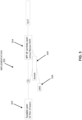
- an implementation 500 of the sensor 100 includes the laser source 102 (or the first laser source 202 and the second laser source 204) at section 502 of the sensor 100.
- the bandpass filter 108 (or the bandpass filter 210) are operatively disposed between the laser source 102 and the DUT 104, and are configured to an anti-Stokes wavelength that is narrower than the Raman bandwidth.
- a single photodiode 110 (or the photodiode 212) may be operatively connected to a switch at section 508 of the sensor 100.
- the switch at section 508 of the sensor 100 may be operated so that the photodiode 110 (or the photodiode 212) is operatively disposed between the bandpass filter 108 and the DUT 104 to acquire, from the DUT 104, anti-Stokes optical time-domain reflectometer traces for two preset wavelengths of the laser beam to determine the temperature distribution 112 for the DUT 104. Further, the switch at section 508 of the sensor 100 may be operated so that the photodiode 110 (or the photodiode 212) is operatively disposed between the laser source 102 and the bandpass filter 108 to acquire Rayleigh optical time-domain reflectometer traces at the two preset wavelengths of the laser beam.
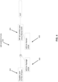
- an implementation 600 of the sensor 100 includes the laser source 102 at section 602 of the sensor 100.
- Laser pulses are be sent to the DUT.
- backscattered radiation may be directed towards bandpass filters linked via wavelength division multiplexing (WDM) to successively record the anti-Stokes Raman OTDR trace at two optical frequencies.
- WDM wavelength division multiplexing
- the switch and fixed filters may be replaced by a tunable filter.
- a differential attenuation between the two preset wavelengths of the laser beam may be corrected by determining a ratio of the Rayleigh optical time-domain reflectometer traces at the two preset wavelengths of the laser beam.
- a tunable laser e.g., 40nm at 1550nm
- a fixed bandpass filter implemented as shown in Figures 4 and 5 may be utilized.
- the two backward Raman wavelength losses may be virtually identical as they are selected by the same bandpass filter.
- the losses at forward pulse wavelengths e.g., forward losses
- the loss in sensitivity to temperature may be equivalent to a loss of dynamic range, for example, by 2.6dB. This value may represent a default value.
- the optics of the implementation may allow to spare approximately 1.4dB of dynamic range (e.g., 5 LOG).
- a wavelength difference resulting from differing anti-Stokes spectral slices and a corresponding mean weighted average wavelength may be corrected.
- a relatively small difference of a few nm may remain in the mean-weighted-average anti-Stokes wavelength due to the Raman spectral shape.
- Figure 7 illustrates a 30nm bandpass filtered anti-stokes Raman spectra with test wavelengths at min-max of Erbium/C-band, according to an example of the present disclosure.
- this aspect may be evaluated in the graphic of Figure 7 of the expected filtered spectra with two test wavelengths, for example, at 1529 and 1569nm, and a bandpass of 30nm.
- these curves may represent the two Raman spectra of backscattered radiation that is obtained when sending laser light at 1529 and 1569nm, respectively.
- the spectra for the example of Figure 7 may be windowed by the bandpass rectangular profile.
- the test wavelengths may be at the extremes of the C-band of fiber telecommunications, where sources and erbium doped fibers may be utilized.
- scaling may be based on the width of bandpass (e.g., 3nm for a 30nm bandwidth for the following example), so that the difference may be reduced, at the cost of a lower signal power and therefore a lower dynamic range.
- a differential loss may be extrapolated at those latter wavelengths to produce a further correction on the fiber losses.
- Reducing the bandwidth of the Stokes band by use of a bandpass filter may provide for the reduction of the chromatic dispersion induced spatial spread and associated loss of spatial resolution, for example, in monomode fiber applications.
- multimode applications may be primarily affected by modal dispersion.
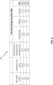
- Figure 8 illustrates a table of various consequences of bandpass filter width, as a guideline for the determination of an optimal value, according to an example of the present disclosure.
- a lower bandwidth may improve the wavelength definition (remaining differential loss problem) and the potential to reach longer distances while maintaining spatial resolution (CD problem). Further, a larger bandwidth may be utilized to maintain the dynamic range of an instrument (e.g., proportionally higher power).
- the columns of Figure 8 may include bandpass filter width (nm), lambda error (nm), spread due to backward chromatic dispersion (CD) at 30 km (m), sensitivity, power, losses, and bill.
- the two anti-Stokes powers at the two spectral slices may follow Bose-Einstein statistics as follows: I AS T , ⁇ ⁇ 1 , 2 ⁇ 1 exp h ⁇ ⁇ 1 , 2 kT ⁇ 1
- I AS represents the intensity detected
- T represents the temperature
- ⁇ 1,2 represents the mean-weighted average frequency shift for the anti-Stokes spectral slice considered
- h represents the Planck's constant
- k represents the Boltzmann constant.
- the temperature distribution 112 (or the temperature distribution 214) for the DUT may be determined by determining a ratio of the anti-Stokes optical time-domain reflectometer traces for the two preset wavelengths of the laser beam.
- the ratio of the two Stokes may be derived from OTDR traces for every point of the link.
- the ratio may be normalized to the ratio measured in a reference section at a known temperature T 0 as follows (this may provide for elimination of the constants of proportionality disregarded in Equation (4)):
- R represents the anti-Stokes to Stokes ratio
- ⁇ 1 represents the mean-weighted average frequency shift for spectral slice 1
- ⁇ 2 represents the mean-weighted average frequency shift for spectral slice 2.
- Equation (5) may be solved numerically to derive T all along the fiber from a measured ratio.
- the temperature distribution sensor 100 as disclosed herein may include a single source or a single-band solution.
- the temperature distribution sensor 100 may include a relatively small tuning range or in an embodiment included to aid understanding dual source, 20nm broad/apart at 1064nm, 40nm broad/apart at 1550nm.
- the temperature distribution sensor 100 as disclosed herein may include a single source as disclosed herein.
- C-Band components at 1550nm, C-Band components, fiber lasers, and fiber amplifiers based on Erbium dopant may be utilized.
- fiber lasers at 1550nm, C-Band components, fiber lasers, and fiber amplifiers based on Erbium dopant may be utilized.
- fiber amplifiers based on Erbium dopant may be utilized.
- Y-Band components and their capacity at producing 1040-1068nm light may be utilized.
- the temperature distribution sensor 100 as disclosed herein may provide for compensation of differential slope (e.g., with bending or bleaching). This may be associated with the same wavelength band in the anti-Stokes range (e.g., a power slope within band which create differing mean wavelengths anti-Stokes-1 (AS1) and anti-Stokes-2 (AS2), and two different probe wavelengths (e.g., 40nm compared to the 100nm of the dual-laser solution of Figure 2 ). Differential fiber losses may be measured in Rayleigh mode at these two test probe wavelengths.
- differential slope e.g., with bending or bleaching
- the four slopes may provide for the quantification of the whole link (e.g., Rayleigh 1 (lambda 1 forward and lambda 1 backward), Rayleigh 2 (lambda 2 forward and lambda 2 backward), AS1 (lambda 1 forward and AS1 backward) and AS2 (lambda 2 forward and AS2 backward).
- Rayleigh 1 (lambda 1 forward and lambda 1 backward)
- Rayleigh 2 (lambda 2 forward and lambda 2 backward)
- AS1 laambda 1 forward and AS1 backward
- AS2 laambda 2 forward and AS2 backward
- the temperature distribution sensor 100 as disclosed herein may provide for a single-ended test for temperature distribution.
- the temperature distribution sensor 100 as disclosed herein may eliminate the need for a dual-ended test, which may include installation constraints which may not be possible to implement.
- the temperature distribution sensor 100 as disclosed herein may provide for an intrinsic tolerance to nonlinearity.
- the two test probes and backscattered signals may be considered as equal with regard to non-linearity given the very similar wavelengths, power levels, and fiber attenuation profiles.
- the nonlinearity may affect each measure differently (e.g., Anti-Stokes retrofitting energy to forward pulse, Rayleigh depleted by co-propagating forward Stokes pulses, Stokes band increased by Rayleigh scattering of the same forward Stokes pulse, etc.).
- the laser source may include a narrow linewidth tunable laser.
- the sensor 100 may be operated using the narrow linewidth tunable laser source in a Rayleigh mode to record a distributed acoustic sensing signal over the DUT.
- use of a narrow linewidth laser may provide for compatibility with a distributed acoustic sensing option.
- the Rayleigh section of the new distributed temperature sensing scheme previously described may include a direct-detection acquisition line that is also compatible with an intensity based distributed acoustic sensing.
- a coherent detection scheme may provide a suitable mean for the differential slope compensations at source wavelengths, while also providing a higher sensitivity for an intelligent distributed acoustic sensor and the potential for a Phase-distributed acoustic sensing analysis.
- a distributed temperature sensing and a distributed acoustic sensing interrogator may be used alternatively and even simultaneously on the same sensing fiber with added value when crossing the respective information for these interrogators.
- Disposal of a tunable laser in the distributed acoustic sensing application with respect to wavelength diversity may provide for the reduction of the fading of the sensor response at locations of destructive interferences.
- the narrow linewidth laser and narrow-filtered Raman signal may reduce the chromatic dispersion effect, which may limit the spatial resolution in long-distance monomode applications.
- the temperature distribution sensor 100 as disclosed herein may be applicable to multimode applications.
- the temperature distribution sensor 100 may require limited tunability (e.g., 20nm @1064nm) and a narrower bandpass.
- a narrow bandpass filter may be used for the purpose of reducing the chromatic-dispersion-related loss of spatial resolution. This loss may be overcome with relatively large pulse power, and a higher power compared to all existing solutions that are affected by nonlinearity issues.
- the temperature distribution sensor 100 as disclosed herein may include a fiber amplifier and utilize larger peak powers than otherwise possible, which may result in a net gain on the dynamic range.
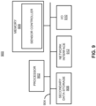
- Figure 9 shows a computer system 900 that may be used with the examples described herein.
- the computer system may represent a generic platform that includes components that may be in a server or another computer system.
- the computer system 900 may be used as part of a platform for the sensor controller of Figure 1 and/or Figure 2 .
- the computer system 900 may execute, by a processor (e.g., a single or multiple processors) or other hardware processing circuit, the methods, functions and other processes described herein.
- a processor e.g., a single or multiple processors
- a computer readable medium which may be non-transitory, such as hardware storage devices (e.g., RAM (random access memory), ROM (read only memory), EPROM (erasable, programmable ROM), EEPROM (electrically erasable, programmable ROM), hard drives, and flash memory).
- RAM random access memory
- ROM read only memory
- EPROM erasable, programmable ROM
- EEPROM electrically erasable, programmable ROM
- hard drives e.g., hard drives, and flash memory
- the computer system 900 may include a processor 902 that may implement or execute machine readable instructions performing some or all of the methods, functions and other processes described herein. Commands and data from the processor 902 may be communicated over a communication bus 904.
- the computer system may also include a main memory 906, such as a random access memory (RAM), where the machine readable instructions and data for the processor 902 may reside during runtime, and a secondary data storage 908, which may be non-volatile and stores machine readable instructions and data.
- the memory and data storage are examples of computer readable mediums.
- the memory 906 may include the sensor controller of Figure 1 and/or Figure 2 including machine readable instructions residing in the memory 906 during runtime and executed by the processor 902.
- the computer system 900 may include an I/O device 910, such as a keyboard, a mouse, a display, etc.
- the computer system may include a network interface 912 for connecting to a network.
- Other known electronic components may be added or substituted in the computer system.
- the processor 902 may be designated as a hardware processor.
- the processor 902 may execute operations associated with various components of the sensor 100.
- the processor 902 may execute operations associated with the sensor controller of Figure 1 and/or Figure 2 , etc.
- Equation (5) R represents the anti-Stokes to Stokes ratio
- ⁇ 1 represents the mean-weighted average frequency shift for spectral slice 1
- ⁇ 2 represents the mean-weighted average frequency shift for spectral slice 2. Equation (5) may be solved numerically to derive T all along the fiber from a measured ratio.
- the temperature distribution sensor 100 as disclosed herein may include a single source or a single-band solution.
- the temperature distribution sensor 100 may include a relatively small tuning range or dual source, 20nm broad/apart at 1064nm, 40nm broad/apart at 1550nm.
- the temperature distribution sensor 100 as disclosed herein may include a single source as disclosed herein.
- C-Band components at 1550nm, C-Band components, fiber lasers, and fiber amplifiers based on Erbium dopant may be utilized.
- fiber lasers at 1550nm, C-Band components, fiber lasers, and fiber amplifiers based on Erbium dopant may be utilized.
- fiber amplifiers based on Erbium dopant may be utilized.
- Y-Band components and their capacity at producing 1040-1068nm light may be utilized.
- the temperature distribution sensor 100 as disclosed herein may provide for compensation of differential slope (e.g., with bending or bleaching). This may be associated with the same wavelength band in the anti-Stokes range (e.g., a power slope within band which create differing mean wavelengths anti-Stokes-1 (AS1) and anti-Stokes-2 (AS2), and two different probe wavelengths (e.g., 40nm compared to the 100nm of the dual-laser solution of Figure 2 ). Differential fiber losses may be measured in Rayleigh mode at these two test probe wavelengths.
- differential slope e.g., with bending or bleaching
- the four slopes may provide for the quantification of the whole link (e.g., Rayleigh 1 (lambda 1 forward and lambda 1 backward), Rayleigh 2 (lambda 2 forward and lambda 2 backward), AS1 (lambda 1 forward and AS1 backward) and AS2 (lambda 2 forward and AS2 backward).
- Rayleigh 1 (lambda 1 forward and lambda 1 backward)
- Rayleigh 2 (lambda 2 forward and lambda 2 backward)
- AS1 laambda 1 forward and AS1 backward
- AS2 laambda 2 forward and AS2 backward
- the temperature distribution sensor 100 as disclosed herein may provide for a single-ended test for temperature distribution.
- the temperature distribution sensor 100 as disclosed herein may eliminate the need for a dual-ended test, which may include installation constraints which may not be possible to implement.
- the temperature distribution sensor 100 as disclosed herein may provide for an intrinsic tolerance to nonlinearity.
- the two test probes and backscattered signals may be considered as equal with regard to non-linearity given the very similar wavelengths, power levels, and fiber attenuation profiles.
- the nonlinearity may affect each measure differently (e.g., Anti-Stokes retrofitting energy to forward pulse, Rayleigh depleted by co-propagating forward Stokes pulses, Stokes band increased by Rayleigh scattering of the same forward Stokes pulse, etc.).
- the laser source may include a narrow linewidth tunable laser.
- the sensor 100 may be operated using the narrow linewidth tunable laser source in a Rayleigh mode to record a distributed acoustic sensing signal over the DUT.
- use of a narrow linewidth laser may provide for compatibility with a distributed acoustic sensing option.
- the Rayleigh section of the new distributed temperature sensing scheme previously described may include a direct-detection acquisition line that is also compatible with an intensity based distributed acoustic sensing.
- a coherent detection scheme may provide a suitable mean for the differential slope compensations at source wavelengths, while also providing a higher sensitivity for an intelligent distributed acoustic sensor and the potential for a Phase-distributed acoustic sensing analysis.
- a distributed temperature sensing and a distributed acoustic sensing interrogator may be used alternatively and even simultaneously on the same sensing fiber with added value when crossing the respective information for these interrogators.
- Disposal of a tunable laser in the distributed acoustic sensing application with respect to wavelength diversity may provide for the reduction of the fading of the sensor response at locations of destructive interferences.
- the narrow linewidth laser and narrow-filtered Raman signal may reduce the chromatic dispersion effect, which may limit the spatial resolution in long-distance monomode applications.
- the temperature distribution sensor 100 as disclosed herein may be applicable to multimode applications.
- the temperature distribution sensor 100 may require limited tunability (e.g., 20nm @1064nm) and a narrower bandpass.
- a narrow bandpass filter may be used for the purpose of reducing the chromatic-dispersion-related loss of spatial resolution. This loss may be overcome with relatively large pulse power, and a higher power compared to all existing solutions that are affected by nonlinearity issues.
- the temperature distribution sensor 100 as disclosed herein may include a fiber amplifier and utilize larger peak powers than otherwise possible, which may result in a net gain on the dynamic range.
- Figure 9 shows a computer system 900 that may be used with the examples described herein.
- the computer system may represent a generic platform that includes components that may be in a server or another computer system.
- the computer system 900 may be used as part of a platform for the sensor controller of Figure 1 and/or Figure 2 .
- the computer system 900 may execute, by a processor (e.g., a single or multiple processors) or other hardware processing circuit, the methods, functions and other processes described herein.
- a processor e.g., a single or multiple processors
- a computer readable medium which may be non-transitory, such as hardware storage devices (e.g., RAM (random access memory), ROM (read only memory), EPROM (erasable, programmable ROM), EEPROM (electrically erasable, programmable ROM), hard drives, and flash memory).
- RAM random access memory
- ROM read only memory
- EPROM erasable, programmable ROM
- EEPROM electrically erasable, programmable ROM
- hard drives e.g., hard drives, and flash memory
- the computer system 900 may include a processor 902 that may implement or execute machine readable instructions performing some or all of the methods, functions and other processes described herein. Commands and data from the processor 902 may be communicated over a communication bus 904.
- the computer system may also include a main memory 906, such as a random access memory (RAM), where the machine readable instructions and data for the processor 902 may reside during runtime, and a secondary data storage 908, which may be non-volatile and stores machine readable instructions and data.
- the memory and data storage are examples of computer readable mediums.
- the memory 906 may include the sensor controller of Figure 1 and/or Figure 2 including machine readable instructions residing in the memory 906 during runtime and executed by the processor 902.
- the computer system 900 may include an I/O device 910, such as a keyboard, a mouse, a display, etc.
- the computer system may include a network interface 912 for connecting to a network.
- Other known electronic components may be added or substituted in the computer system.
- the processor 902 may be designated as a hardware processor.
- the processor 902 may execute operations associated with various components of the sensor 100.
- the processor 902 may execute operations associated with the sensor controller of Figure 1 and/or Figure 2 , etc.
Landscapes
- Physics & Mathematics (AREA)
- General Physics & Mathematics (AREA)
- Measuring Temperature Or Quantity Of Heat (AREA)
- Radiation Pyrometers (AREA)
Claims (8)
- Ein computerimplementiertes Verfahren, beinhaltend:Emittieren, von einer Laserquelle (102), eines Laserstrahls, der über einen Wellenlängenbereich abstimmbar ist, dadurch gekennzeichnet, dass der Wellenlängenbereichkleiner als eine Raman-Bandbreite in einer zu prüfenden Vorrichtung (104), DUT, ist oderin der Größenordnung der Raman-Bandbreite in der DUT (104) liegt;Anwenden eines Impulsansteuersignals auf den Laserstrahl oder auf einen Modulator, um den Laserstrahl, der in die DUT (104) eingekoppelt werden soll, zu modulieren;Konfigurieren eines Bandpassfilters (108), das zwischen der Laserquelle (102) und der DUT (104) betriebsbereit angeordnet ist, auf eine Anti-Stokes-Wellenlänge, die schmaler als die Raman-Bandbreite ist; undBestimmen einer Temperaturverteilung für die DUT (104) durch das Erfassen, von der DUT (104), von optischen Anti-Stokes-Zeitbereichsreflektometerverläufen für zwei voreingestellte Wellenlängen des Laserstrahls.
- Verfahren gemäß Anspruch 1, wobei die DUT (104) eine optische Faser umfasst.
- Verfahren gemäß Anspruch 1, ferner beinhaltend:
Erfassen von optischen Rayleigh-Zeitbereichsreflektometerverläufen bei den zwei voreingestellten Wellenlängen des Laserstrahls. - Verfahren gemäß Anspruch 3, ferner beinhaltend:
Korrigieren einer differentiellen Dämpfung zwischen den zwei voreingestellten Wellenlängen des Laserstrahls durch das Bestimmen eines Verhältnisses der optischen Rayleigh-Zeitbereichsreflektometerverläufe bei den zwei voreingestellten Wellenlängen des Laserstrahls. - Verfahren gemäß Anspruch 1, wobei das Bestimmen der Temperaturverteilung für die DUT (104) durch das Erfassen, von der DUT (104), der optischen Anti-Stokes-Zeitbereichsreflektometerverläufe für die zwei voreingestellten Wellenlängen des Laserstrahls ferner Folgendes beinhaltet:
Bestimmen der Temperaturverteilung für die DUT (104) durch das Bestimmen eines Verhältnisses der optischen Anti-Stokes-Zeitbereichsreflektometerverläufe für die zwei voreingestellten Wellenlängen des Laserstrahls. - Verfahren gemäß Anspruch 1, ferner beinhaltend:
Verstärken des Impulsansteuersignals, das auf den Laserstrahl oder auf den Modulator angewendet wird, um den Laserstrahl, der in die DUT (104) eingekoppelt werden soll, zu modulieren. - Verfahren gemäß Anspruch 1, ferner beinhaltend:
Korrigieren, für die optischen Anti-Stokes-Zeitbereichsreflektometerverläufe für die zwei voreingestellten Wellenlängen des Laserstrahls, einer Wellenlängendifferenz, die sich aus unterschiedlichen spektralen Anti-Stokes-Slices ergibt, und einer entsprechenden mittleren gewichteten Durchschnittswellenlänge. - Verfahren gemäß Anspruch 1, wobei die Laserquelle (102) ein abstimmbarer Laser mit schmaler Linienbreite ist, ferner beinhaltend:
Arbeiten, unter Verwendung der abstimmbaren Laserquelle (102) mit schmaler Linienbreite, in einem Rayleigh-Modus, um ein verteiltes akustisches Abtastsignal über die DUT (104) aufzuzeichnen.
Applications Claiming Priority (3)
| Application Number | Priority Date | Filing Date | Title |
|---|---|---|---|
| FR1852068 | 2018-03-09 | ||
| US15/945,501 US10775246B2 (en) | 2018-03-09 | 2018-04-04 | Single-band distributed temperature sensing |
| EP19154359.4A EP3584554A1 (de) | 2018-03-09 | 2019-01-29 | Einbandiges verteiltes temperaturmessverfahren |
Related Parent Applications (1)
| Application Number | Title | Priority Date | Filing Date |
|---|---|---|---|
| EP19154359.4A Division EP3584554A1 (de) | 2018-03-09 | 2019-01-29 | Einbandiges verteiltes temperaturmessverfahren |
Publications (4)
| Publication Number | Publication Date |
|---|---|
| EP4239300A2 EP4239300A2 (de) | 2023-09-06 |
| EP4239300A3 EP4239300A3 (de) | 2023-11-15 |
| EP4239300C0 EP4239300C0 (de) | 2025-03-26 |
| EP4239300B1 true EP4239300B1 (de) | 2025-03-26 |
Family
ID=67842441
Family Applications (2)
| Application Number | Title | Priority Date | Filing Date |
|---|---|---|---|
| EP23183139.7A Active EP4239300B1 (de) | 2018-03-09 | 2019-01-29 | Verteilte einband-temperaturmessung |
| EP19154359.4A Ceased EP3584554A1 (de) | 2018-03-09 | 2019-01-29 | Einbandiges verteiltes temperaturmessverfahren |
Family Applications After (1)
| Application Number | Title | Priority Date | Filing Date |
|---|---|---|---|
| EP19154359.4A Ceased EP3584554A1 (de) | 2018-03-09 | 2019-01-29 | Einbandiges verteiltes temperaturmessverfahren |
Country Status (2)
| Country | Link |
|---|---|
| US (3) | US10775246B2 (de) |
| EP (2) | EP4239300B1 (de) |
Families Citing this family (9)
| Publication number | Priority date | Publication date | Assignee | Title |
|---|---|---|---|---|
| CN107532948B (zh) * | 2015-05-13 | 2020-05-19 | 富士通株式会社 | 温度测量装置、温度测量方法以及存储介质 |
| US11378443B2 (en) * | 2019-05-22 | 2022-07-05 | Nec Corporation | Performance of Rayleigh-based phase-OTDR with correlation-based diversity combining and bias removal |
| CN113091946B (zh) * | 2021-04-19 | 2023-05-26 | 太原理工大学 | 混沌分布式光纤拉曼温度传感装置及方法 |
| CN113448363B (zh) * | 2021-07-08 | 2022-05-20 | 中国科学院苏州生物医学工程技术研究所 | 拉曼光学设备自动化控制系统 |
| EP4155708A1 (de) | 2021-09-24 | 2023-03-29 | Viavi Solutions Inc. | Optisches zeitbereichsreflektometer (otdr) einschliesslich kanalprüfer |
| US11942986B2 (en) * | 2021-09-24 | 2024-03-26 | Viavi Solutions Inc. | Optical time-domain reflectometer (OTDR) including channel checker |
| US12359964B2 (en) * | 2022-10-14 | 2025-07-15 | Network Integrity Systems, Inc. | Monitoring optical fibers using two dissimilar algorithms on a single monitoring system |
| IT202300009699A1 (it) * | 2023-05-15 | 2024-11-15 | Infibra Tech S R L | Sistema e metodo di misura di un parametro fisico distribuito di un dispositivo ottico sotto test |
| EP4592649A1 (de) | 2024-01-23 | 2025-07-30 | Viavi Solutions Inc. | Direkte steuerung der laserfrequenz für verteilte akustische doppelimpulsmessung (das) |
Family Cites Families (24)
| Publication number | Priority date | Publication date | Assignee | Title |
|---|---|---|---|---|
| US5696863A (en) * | 1982-08-06 | 1997-12-09 | Kleinerman; Marcos Y. | Distributed fiber optic temperature sensors and systems |
| JP2575324B2 (ja) * | 1991-03-02 | 1997-01-22 | 株式会社フジクラ | 光ファイバ式温度分布測定装置 |
| US20030234921A1 (en) * | 2002-06-21 | 2003-12-25 | Tsutomu Yamate | Method for measuring and calibrating measurements using optical fiber distributed sensor |
| GB2400906B (en) * | 2003-04-24 | 2006-09-20 | Sensor Highway Ltd | Distributed optical fibre measurements |
| ATE401558T1 (de) * | 2004-09-10 | 2008-08-15 | Lios Technology Gmbh | Kalibrierung eines optischen fmcw- rückstreuungsmesssystems |
| US7585107B2 (en) * | 2006-01-17 | 2009-09-08 | Weatherford/Lamb, Inc. | Corrected DTS measurements based on Raman-Stokes signals |
| KR100930342B1 (ko) * | 2007-06-29 | 2009-12-10 | 주식회사 싸이트로닉 | 분포 광섬유 센서 시스템 |
| US8496376B2 (en) | 2007-07-18 | 2013-07-30 | Sensortran, Inc. | Dual source auto-correction in distributed temperature systems |
| WO2009092436A1 (en) | 2008-01-21 | 2009-07-30 | Ap Sensing Gmbh | Distributed temperature sensing using two wavelengths differing by a raman shift of a waveguide |
| DE102008017740A1 (de) * | 2008-04-07 | 2009-10-15 | Lios Technology Gmbh | Vorrichtung und Verfahren zur Kalibrierung eines faseroptischen Temperaturmesssystems |
| WO2010036360A2 (en) * | 2008-09-27 | 2010-04-01 | Sensortran, Inc. | Auto-correcting or self-calibrating dts temperature sensing sytems and methods |
| JP5322184B2 (ja) * | 2008-11-27 | 2013-10-23 | ニューブレクス株式会社 | 分布型光ファイバセンサ |
| CN101825498B (zh) * | 2010-04-13 | 2012-03-21 | 中国计量学院 | 色散与损耗光谱自校正分布式光纤拉曼温度传感器 |
| KR101207345B1 (ko) * | 2010-08-05 | 2012-12-05 | 한국표준과학연구원 | 자동보정 기능을 갖는 광섬유 분포 온도 센서 시스템 및 이를 이용한 온도 측정방법 |
| CA2906964A1 (en) * | 2013-03-18 | 2014-09-25 | Omnisens Sa | Brillouin optical distributed sensing device and method with improved tolerance to sensor failure |
| US9964453B2 (en) * | 2014-03-14 | 2018-05-08 | Optromix Company | Device and method for high precision fiber-optic temperature profile measurements in long length areas |
| JP6020521B2 (ja) * | 2014-07-16 | 2016-11-02 | 横河電機株式会社 | 光ファイバ温度分布測定装置 |
| WO2016008662A1 (en) * | 2014-07-17 | 2016-01-21 | Infibra Technologies S.R.L. | Method and apparatus for measuring a distributed physical value of an optical device under test |
| CN105758433B (zh) * | 2016-03-02 | 2018-04-03 | 南昌工程学院 | 一种基于布里渊光纤激光器的分布式光纤传感装置 |
| CA3023766C (en) * | 2016-07-22 | 2023-09-05 | Halliburton Energy Services, Inc. | A fiber optic interrogation system for multiple distributed sensing systems |
| US9983094B2 (en) * | 2016-09-09 | 2018-05-29 | Viavi Solutions Inc. | Temperature or strain distribution sensor comprising a coherent receiver to determine a temperature or a strain associated with a device under test |
| CN106643544A (zh) * | 2017-02-23 | 2017-05-10 | 鞍山睿科光电技术有限公司 | 一种温度增敏型分布式布里渊光纤传感器 |
| IL254803B2 (en) * | 2017-09-29 | 2023-09-01 | Prisma Photonics Ltd | Distributed amplification optimized for fiber sensing |
| DE102017129637A1 (de) * | 2017-12-12 | 2019-06-13 | Westfälische Wilhelms-Universität Münster | Ultrakurz-Impulslasersystem mit schnell abstimmbarer Zentralwellenlänge |
-
2018
- 2018-04-04 US US15/945,501 patent/US10775246B2/en active Active
-
2019
- 2019-01-29 EP EP23183139.7A patent/EP4239300B1/de active Active
- 2019-01-29 EP EP19154359.4A patent/EP3584554A1/de not_active Ceased
-
2020
- 2020-08-17 US US16/995,498 patent/US11255734B2/en active Active
-
2022
- 2022-01-24 US US17/583,000 patent/US11703398B2/en active Active
Also Published As
| Publication number | Publication date |
|---|---|
| EP4239300C0 (de) | 2025-03-26 |
| EP3584554A1 (de) | 2019-12-25 |
| EP4239300A3 (de) | 2023-11-15 |
| US10775246B2 (en) | 2020-09-15 |
| US11703398B2 (en) | 2023-07-18 |
| EP4239300A2 (de) | 2023-09-06 |
| US20220146332A1 (en) | 2022-05-12 |
| US20200378842A1 (en) | 2020-12-03 |
| US11255734B2 (en) | 2022-02-22 |
| US20190277707A1 (en) | 2019-09-12 |
Similar Documents
| Publication | Publication Date | Title |
|---|---|---|
| EP4239300B1 (de) | Verteilte einband-temperaturmessung | |
| US7284903B2 (en) | Distributed optical fibre measurements | |
| EP2702353B1 (de) | Verteilte brillouin-messsysteme und verfahren dafür unter verwendung von mehrmodus-mess-glasfasern | |
| EP1338877B1 (de) | Optische Reflexionsmessung im Zeitbereich | |
| US20120127459A1 (en) | Distributed Optical Fibre Sensing | |
| US9958300B2 (en) | Time division multiplexing (TDM) and wavelength division multiplexing (WDM) fast-sweep interrogator | |
| CN101556193A (zh) | 用于校准纤维光学温度测量系统的装置和方法 | |
| US20070046928A1 (en) | Method of evaluating fiber pmd using potdr trace | |
| Leandro et al. | Remote (155 km) fiber bragg grating interrogation technique combining Raman, Brillouin, and erbium gain in a fiber laser | |
| CN117213659A (zh) | 基于布里渊和瑞利散射的混沌botdr装置及方法 | |
| US6417926B1 (en) | Wavelength measuring system | |
| JP2005283372A (ja) | Ase光源とラマン増幅を使用したfbgによる温度または歪み測定装置 | |
| JP2004361284A (ja) | 反射波長計測システム | |
| EP3605048A1 (de) | Doppelwellenlängenverteilte temperaturmessung mit eingebauter faserintegritätsüberwachung | |
| Poddubrovskii et al. | BOTDR based on a self-sweeping fiber laser | |
| KR102644918B1 (ko) | 감도 향상형 광섬유 음향 분포센서 | |
| Sudhan et al. | An Optimized Multiplexing System for Remote Sensing Optical Signals | |
| CN119812923A (zh) | 基于随机光纤激光器的u波段相关光时域反射仪 | |
| Magne et al. | Chirped Fiber Bragg gratings for distributed detonation velocity measurements | |
| De Souza | Signal-to-noise enhancement ofa distributed fibre-optic temperature sensor using optical preamplification |
Legal Events
| Date | Code | Title | Description |
|---|---|---|---|
| PUAI | Public reference made under article 153(3) epc to a published international application that has entered the european phase |
Free format text: ORIGINAL CODE: 0009012 |
|
| STAA | Information on the status of an ep patent application or granted ep patent |
Free format text: STATUS: THE APPLICATION HAS BEEN PUBLISHED |
|
| AC | Divisional application: reference to earlier application |
Ref document number: 3584554 Country of ref document: EP Kind code of ref document: P |
|
| AK | Designated contracting states |
Kind code of ref document: A2 Designated state(s): AL AT BE BG CH CY CZ DE DK EE ES FI FR GB GR HR HU IE IS IT LI LT LU LV MC MK MT NL NO PL PT RO RS SE SI SK SM TR |
|
| PUAL | Search report despatched |
Free format text: ORIGINAL CODE: 0009013 |
|
| AK | Designated contracting states |
Kind code of ref document: A3 Designated state(s): AL AT BE BG CH CY CZ DE DK EE ES FI FR GB GR HR HU IE IS IT LI LT LU LV MC MK MT NL NO PL PT RO RS SE SI SK SM TR |
|
| RIC1 | Information provided on ipc code assigned before grant |
Ipc: G01K 13/20 20210101ALI20231011BHEP Ipc: G01K 1/024 20210101ALI20231011BHEP Ipc: G01K 11/324 20210101ALI20231011BHEP Ipc: G01K 11/32 20210101AFI20231011BHEP |
|
| STAA | Information on the status of an ep patent application or granted ep patent |
Free format text: STATUS: REQUEST FOR EXAMINATION WAS MADE |
|
| 17P | Request for examination filed |
Effective date: 20240515 |
|
| RBV | Designated contracting states (corrected) |
Designated state(s): AL AT BE BG CH CY CZ DE DK EE ES FI FR GB GR HR HU IE IS IT LI LT LU LV MC MK MT NL NO PL PT RO RS SE SI SK SM TR |
|
| GRAP | Despatch of communication of intention to grant a patent |
Free format text: ORIGINAL CODE: EPIDOSNIGR1 |
|
| STAA | Information on the status of an ep patent application or granted ep patent |
Free format text: STATUS: GRANT OF PATENT IS INTENDED |
|
| INTG | Intention to grant announced |
Effective date: 20241014 |
|
| GRAS | Grant fee paid |
Free format text: ORIGINAL CODE: EPIDOSNIGR3 |
|
| GRAA | (expected) grant |
Free format text: ORIGINAL CODE: 0009210 |
|
| STAA | Information on the status of an ep patent application or granted ep patent |
Free format text: STATUS: THE PATENT HAS BEEN GRANTED |
|
| AC | Divisional application: reference to earlier application |
Ref document number: 3584554 Country of ref document: EP Kind code of ref document: P |
|
| AK | Designated contracting states |
Kind code of ref document: B1 Designated state(s): AL AT BE BG CH CY CZ DE DK EE ES FI FR GB GR HR HU IE IS IT LI LT LU LV MC MK MT NL NO PL PT RO RS SE SI SK SM TR |
|
| REG | Reference to a national code |
Ref country code: GB Ref legal event code: FG4D |
|
| REG | Reference to a national code |
Ref country code: CH Ref legal event code: EP |
|
| REG | Reference to a national code |
Ref country code: DE Ref legal event code: R096 Ref document number: 602019067989 Country of ref document: DE |
|
| REG | Reference to a national code |
Ref country code: IE Ref legal event code: FG4D |
|
| U01 | Request for unitary effect filed |
Effective date: 20250408 |
|
| U07 | Unitary effect registered |
Designated state(s): AT BE BG DE DK EE FI FR IT LT LU LV MT NL PT RO SE SI Effective date: 20250414 |
|
| PG25 | Lapsed in a contracting state [announced via postgrant information from national office to epo] |
Ref country code: RS Free format text: LAPSE BECAUSE OF FAILURE TO SUBMIT A TRANSLATION OF THE DESCRIPTION OR TO PAY THE FEE WITHIN THE PRESCRIBED TIME-LIMIT Effective date: 20250626 |
|
| PG25 | Lapsed in a contracting state [announced via postgrant information from national office to epo] |
Ref country code: NO Free format text: LAPSE BECAUSE OF FAILURE TO SUBMIT A TRANSLATION OF THE DESCRIPTION OR TO PAY THE FEE WITHIN THE PRESCRIBED TIME-LIMIT Effective date: 20250626 |
|
| PG25 | Lapsed in a contracting state [announced via postgrant information from national office to epo] |
Ref country code: HR Free format text: LAPSE BECAUSE OF FAILURE TO SUBMIT A TRANSLATION OF THE DESCRIPTION OR TO PAY THE FEE WITHIN THE PRESCRIBED TIME-LIMIT Effective date: 20250326 |
|
| PG25 | Lapsed in a contracting state [announced via postgrant information from national office to epo] |
Ref country code: GR Free format text: LAPSE BECAUSE OF FAILURE TO SUBMIT A TRANSLATION OF THE DESCRIPTION OR TO PAY THE FEE WITHIN THE PRESCRIBED TIME-LIMIT Effective date: 20250627 |
|
| PG25 | Lapsed in a contracting state [announced via postgrant information from national office to epo] |
Ref country code: SM Free format text: LAPSE BECAUSE OF FAILURE TO SUBMIT A TRANSLATION OF THE DESCRIPTION OR TO PAY THE FEE WITHIN THE PRESCRIBED TIME-LIMIT Effective date: 20250326 |
|
| PG25 | Lapsed in a contracting state [announced via postgrant information from national office to epo] |
Ref country code: ES Free format text: LAPSE BECAUSE OF FAILURE TO SUBMIT A TRANSLATION OF THE DESCRIPTION OR TO PAY THE FEE WITHIN THE PRESCRIBED TIME-LIMIT Effective date: 20250326 |
|
| PG25 | Lapsed in a contracting state [announced via postgrant information from national office to epo] |
Ref country code: PL Free format text: LAPSE BECAUSE OF FAILURE TO SUBMIT A TRANSLATION OF THE DESCRIPTION OR TO PAY THE FEE WITHIN THE PRESCRIBED TIME-LIMIT Effective date: 20250326 |
|
| PG25 | Lapsed in a contracting state [announced via postgrant information from national office to epo] |
Ref country code: SK Free format text: LAPSE BECAUSE OF FAILURE TO SUBMIT A TRANSLATION OF THE DESCRIPTION OR TO PAY THE FEE WITHIN THE PRESCRIBED TIME-LIMIT Effective date: 20250326 |
|
| PG25 | Lapsed in a contracting state [announced via postgrant information from national office to epo] |
Ref country code: IS Free format text: LAPSE BECAUSE OF FAILURE TO SUBMIT A TRANSLATION OF THE DESCRIPTION OR TO PAY THE FEE WITHIN THE PRESCRIBED TIME-LIMIT Effective date: 20250726 |
|
| PG25 | Lapsed in a contracting state [announced via postgrant information from national office to epo] |
Ref country code: CZ Free format text: LAPSE BECAUSE OF FAILURE TO SUBMIT A TRANSLATION OF THE DESCRIPTION OR TO PAY THE FEE WITHIN THE PRESCRIBED TIME-LIMIT Effective date: 20250326 |
|
| PLBE | No opposition filed within time limit |
Free format text: ORIGINAL CODE: 0009261 |
|
| STAA | Information on the status of an ep patent application or granted ep patent |
Free format text: STATUS: NO OPPOSITION FILED WITHIN TIME LIMIT |
|
| REG | Reference to a national code |
Ref country code: CH Ref legal event code: L10 Free format text: ST27 STATUS EVENT CODE: U-0-0-L10-L00 (AS PROVIDED BY THE NATIONAL OFFICE) Effective date: 20260211 |
|
| U20 | Renewal fee for the european patent with unitary effect paid |
Year of fee payment: 8 Effective date: 20260129 |
|
| 26N | No opposition filed |
Effective date: 20260105 |
|
| PGFP | Annual fee paid to national office [announced via postgrant information from national office to epo] |
Ref country code: GB Payment date: 20260129 Year of fee payment: 8 |