EP4239226A1 - Electrified vehicle and method for manufacturing electrified vehicle - Google Patents
Electrified vehicle and method for manufacturing electrified vehicle Download PDFInfo
- Publication number
- EP4239226A1 EP4239226A1 EP22211574.3A EP22211574A EP4239226A1 EP 4239226 A1 EP4239226 A1 EP 4239226A1 EP 22211574 A EP22211574 A EP 22211574A EP 4239226 A1 EP4239226 A1 EP 4239226A1
- Authority
- EP
- European Patent Office
- Prior art keywords
- rotational speed
- motor
- clutch
- ecu
- change
- Prior art date
- Legal status (The legal status is an assumption and is not a legal conclusion. Google has not performed a legal analysis and makes no representation as to the accuracy of the status listed.)
- Pending
Links
Images




Classifications
-
- B—PERFORMING OPERATIONS; TRANSPORTING
- B60—VEHICLES IN GENERAL
- B60L—PROPULSION OF ELECTRICALLY-PROPELLED VEHICLES; SUPPLYING ELECTRIC POWER FOR AUXILIARY EQUIPMENT OF ELECTRICALLY-PROPELLED VEHICLES; ELECTRODYNAMIC BRAKE SYSTEMS FOR VEHICLES IN GENERAL; MAGNETIC SUSPENSION OR LEVITATION FOR VEHICLES; MONITORING OPERATING VARIABLES OF ELECTRICALLY-PROPELLED VEHICLES; ELECTRIC SAFETY DEVICES FOR ELECTRICALLY-PROPELLED VEHICLES
- B60L15/00—Methods, circuits, or devices for controlling the traction-motor speed of electrically-propelled vehicles
- B60L15/20—Methods, circuits, or devices for controlling the traction-motor speed of electrically-propelled vehicles for control of the vehicle or its driving motor to achieve a desired performance, e.g. speed, torque, programmed variation of speed
- B60L15/2054—Methods, circuits, or devices for controlling the traction-motor speed of electrically-propelled vehicles for control of the vehicle or its driving motor to achieve a desired performance, e.g. speed, torque, programmed variation of speed by controlling transmissions or clutches
-
- F—MECHANICAL ENGINEERING; LIGHTING; HEATING; WEAPONS; BLASTING
- F16—ENGINEERING ELEMENTS AND UNITS; GENERAL MEASURES FOR PRODUCING AND MAINTAINING EFFECTIVE FUNCTIONING OF MACHINES OR INSTALLATIONS; THERMAL INSULATION IN GENERAL
- F16H—GEARING
- F16H61/00—Control functions within control units of change-speed- or reversing-gearings for conveying rotary motion ; Control of exclusively fluid gearing, friction gearing, gearings with endless flexible members or other particular types of gearing
- F16H61/04—Smoothing ratio shift
-
- B—PERFORMING OPERATIONS; TRANSPORTING
- B60—VEHICLES IN GENERAL
- B60K—ARRANGEMENT OR MOUNTING OF PROPULSION UNITS OR OF TRANSMISSIONS IN VEHICLES; ARRANGEMENT OR MOUNTING OF PLURAL DIVERSE PRIME-MOVERS IN VEHICLES; AUXILIARY DRIVES FOR VEHICLES; INSTRUMENTATION OR DASHBOARDS FOR VEHICLES; ARRANGEMENTS IN CONNECTION WITH COOLING, AIR INTAKE, GAS EXHAUST OR FUEL SUPPLY OF PROPULSION UNITS IN VEHICLES
- B60K1/00—Arrangement or mounting of electrical propulsion units
-
- B—PERFORMING OPERATIONS; TRANSPORTING
- B60—VEHICLES IN GENERAL
- B60L—PROPULSION OF ELECTRICALLY-PROPELLED VEHICLES; SUPPLYING ELECTRIC POWER FOR AUXILIARY EQUIPMENT OF ELECTRICALLY-PROPELLED VEHICLES; ELECTRODYNAMIC BRAKE SYSTEMS FOR VEHICLES IN GENERAL; MAGNETIC SUSPENSION OR LEVITATION FOR VEHICLES; MONITORING OPERATING VARIABLES OF ELECTRICALLY-PROPELLED VEHICLES; ELECTRIC SAFETY DEVICES FOR ELECTRICALLY-PROPELLED VEHICLES
- B60L15/00—Methods, circuits, or devices for controlling the traction-motor speed of electrically-propelled vehicles
- B60L15/007—Physical arrangements or structures of drive train converters specially adapted for the propulsion motors of electric vehicles
-
- B—PERFORMING OPERATIONS; TRANSPORTING
- B60—VEHICLES IN GENERAL
- B60W—CONJOINT CONTROL OF VEHICLE SUB-UNITS OF DIFFERENT TYPE OR DIFFERENT FUNCTION; CONTROL SYSTEMS SPECIALLY ADAPTED FOR HYBRID VEHICLES; ROAD VEHICLE DRIVE CONTROL SYSTEMS FOR PURPOSES NOT RELATED TO THE CONTROL OF A PARTICULAR SUB-UNIT
- B60W10/00—Conjoint control of vehicle sub-units of different type or different function
- B60W10/02—Conjoint control of vehicle sub-units of different type or different function including control of driveline clutches
-
- B—PERFORMING OPERATIONS; TRANSPORTING
- B60—VEHICLES IN GENERAL
- B60W—CONJOINT CONTROL OF VEHICLE SUB-UNITS OF DIFFERENT TYPE OR DIFFERENT FUNCTION; CONTROL SYSTEMS SPECIALLY ADAPTED FOR HYBRID VEHICLES; ROAD VEHICLE DRIVE CONTROL SYSTEMS FOR PURPOSES NOT RELATED TO THE CONTROL OF A PARTICULAR SUB-UNIT
- B60W10/00—Conjoint control of vehicle sub-units of different type or different function
- B60W10/04—Conjoint control of vehicle sub-units of different type or different function including control of propulsion units
- B60W10/08—Conjoint control of vehicle sub-units of different type or different function including control of propulsion units including control of electric propulsion units, e.g. motors or generators
-
- B—PERFORMING OPERATIONS; TRANSPORTING
- B60—VEHICLES IN GENERAL
- B60W—CONJOINT CONTROL OF VEHICLE SUB-UNITS OF DIFFERENT TYPE OR DIFFERENT FUNCTION; CONTROL SYSTEMS SPECIALLY ADAPTED FOR HYBRID VEHICLES; ROAD VEHICLE DRIVE CONTROL SYSTEMS FOR PURPOSES NOT RELATED TO THE CONTROL OF A PARTICULAR SUB-UNIT
- B60W30/00—Purposes of road vehicle drive control systems not related to the control of a particular sub-unit, e.g. of systems using conjoint control of vehicle sub-units
- B60W30/18—Propelling the vehicle
- B60W30/19—Improvement of gear change, e.g. by synchronisation or smoothing gear shift
-
- F—MECHANICAL ENGINEERING; LIGHTING; HEATING; WEAPONS; BLASTING
- F16—ENGINEERING ELEMENTS AND UNITS; GENERAL MEASURES FOR PRODUCING AND MAINTAINING EFFECTIVE FUNCTIONING OF MACHINES OR INSTALLATIONS; THERMAL INSULATION IN GENERAL
- F16H—GEARING
- F16H63/00—Control outputs from the control unit to change-speed- or reversing-gearings for conveying rotary motion or to other devices than the final output mechanism
- F16H63/40—Control outputs from the control unit to change-speed- or reversing-gearings for conveying rotary motion or to other devices than the final output mechanism comprising signals other than signals for actuating the final output mechanisms
- F16H63/50—Signals to an engine or motor
- F16H63/502—Signals to an engine or motor for smoothing gear shifts
-
- B—PERFORMING OPERATIONS; TRANSPORTING
- B60—VEHICLES IN GENERAL
- B60L—PROPULSION OF ELECTRICALLY-PROPELLED VEHICLES; SUPPLYING ELECTRIC POWER FOR AUXILIARY EQUIPMENT OF ELECTRICALLY-PROPELLED VEHICLES; ELECTRODYNAMIC BRAKE SYSTEMS FOR VEHICLES IN GENERAL; MAGNETIC SUSPENSION OR LEVITATION FOR VEHICLES; MONITORING OPERATING VARIABLES OF ELECTRICALLY-PROPELLED VEHICLES; ELECTRIC SAFETY DEVICES FOR ELECTRICALLY-PROPELLED VEHICLES
- B60L2240/00—Control parameters of input or output; Target parameters
- B60L2240/10—Vehicle control parameters
- B60L2240/12—Speed
-
- B—PERFORMING OPERATIONS; TRANSPORTING
- B60—VEHICLES IN GENERAL
- B60L—PROPULSION OF ELECTRICALLY-PROPELLED VEHICLES; SUPPLYING ELECTRIC POWER FOR AUXILIARY EQUIPMENT OF ELECTRICALLY-PROPELLED VEHICLES; ELECTRODYNAMIC BRAKE SYSTEMS FOR VEHICLES IN GENERAL; MAGNETIC SUSPENSION OR LEVITATION FOR VEHICLES; MONITORING OPERATING VARIABLES OF ELECTRICALLY-PROPELLED VEHICLES; ELECTRIC SAFETY DEVICES FOR ELECTRICALLY-PROPELLED VEHICLES
- B60L2240/00—Control parameters of input or output; Target parameters
- B60L2240/40—Drive Train control parameters
- B60L2240/42—Drive Train control parameters related to electric machines
-
- B—PERFORMING OPERATIONS; TRANSPORTING
- B60—VEHICLES IN GENERAL
- B60L—PROPULSION OF ELECTRICALLY-PROPELLED VEHICLES; SUPPLYING ELECTRIC POWER FOR AUXILIARY EQUIPMENT OF ELECTRICALLY-PROPELLED VEHICLES; ELECTRODYNAMIC BRAKE SYSTEMS FOR VEHICLES IN GENERAL; MAGNETIC SUSPENSION OR LEVITATION FOR VEHICLES; MONITORING OPERATING VARIABLES OF ELECTRICALLY-PROPELLED VEHICLES; ELECTRIC SAFETY DEVICES FOR ELECTRICALLY-PROPELLED VEHICLES
- B60L2240/00—Control parameters of input or output; Target parameters
- B60L2240/40—Drive Train control parameters
- B60L2240/48—Drive Train control parameters related to transmissions
-
- B—PERFORMING OPERATIONS; TRANSPORTING
- B60—VEHICLES IN GENERAL
- B60L—PROPULSION OF ELECTRICALLY-PROPELLED VEHICLES; SUPPLYING ELECTRIC POWER FOR AUXILIARY EQUIPMENT OF ELECTRICALLY-PROPELLED VEHICLES; ELECTRODYNAMIC BRAKE SYSTEMS FOR VEHICLES IN GENERAL; MAGNETIC SUSPENSION OR LEVITATION FOR VEHICLES; MONITORING OPERATING VARIABLES OF ELECTRICALLY-PROPELLED VEHICLES; ELECTRIC SAFETY DEVICES FOR ELECTRICALLY-PROPELLED VEHICLES
- B60L2240/00—Control parameters of input or output; Target parameters
- B60L2240/40—Drive Train control parameters
- B60L2240/50—Drive Train control parameters related to clutches
-
- B—PERFORMING OPERATIONS; TRANSPORTING
- B60—VEHICLES IN GENERAL
- B60L—PROPULSION OF ELECTRICALLY-PROPELLED VEHICLES; SUPPLYING ELECTRIC POWER FOR AUXILIARY EQUIPMENT OF ELECTRICALLY-PROPELLED VEHICLES; ELECTRODYNAMIC BRAKE SYSTEMS FOR VEHICLES IN GENERAL; MAGNETIC SUSPENSION OR LEVITATION FOR VEHICLES; MONITORING OPERATING VARIABLES OF ELECTRICALLY-PROPELLED VEHICLES; ELECTRIC SAFETY DEVICES FOR ELECTRICALLY-PROPELLED VEHICLES
- B60L2240/00—Control parameters of input or output; Target parameters
- B60L2240/40—Drive Train control parameters
- B60L2240/50—Drive Train control parameters related to clutches
- B60L2240/507—Operating parameters
-
- B—PERFORMING OPERATIONS; TRANSPORTING
- B60—VEHICLES IN GENERAL
- B60L—PROPULSION OF ELECTRICALLY-PROPELLED VEHICLES; SUPPLYING ELECTRIC POWER FOR AUXILIARY EQUIPMENT OF ELECTRICALLY-PROPELLED VEHICLES; ELECTRODYNAMIC BRAKE SYSTEMS FOR VEHICLES IN GENERAL; MAGNETIC SUSPENSION OR LEVITATION FOR VEHICLES; MONITORING OPERATING VARIABLES OF ELECTRICALLY-PROPELLED VEHICLES; ELECTRIC SAFETY DEVICES FOR ELECTRICALLY-PROPELLED VEHICLES
- B60L2260/00—Operating Modes
- B60L2260/40—Control modes
- B60L2260/44—Control modes by parameter estimation
-
- B—PERFORMING OPERATIONS; TRANSPORTING
- B60—VEHICLES IN GENERAL
- B60L—PROPULSION OF ELECTRICALLY-PROPELLED VEHICLES; SUPPLYING ELECTRIC POWER FOR AUXILIARY EQUIPMENT OF ELECTRICALLY-PROPELLED VEHICLES; ELECTRODYNAMIC BRAKE SYSTEMS FOR VEHICLES IN GENERAL; MAGNETIC SUSPENSION OR LEVITATION FOR VEHICLES; MONITORING OPERATING VARIABLES OF ELECTRICALLY-PROPELLED VEHICLES; ELECTRIC SAFETY DEVICES FOR ELECTRICALLY-PROPELLED VEHICLES
- B60L2260/00—Operating Modes
- B60L2260/40—Control modes
- B60L2260/46—Control modes by self learning
-
- B—PERFORMING OPERATIONS; TRANSPORTING
- B60—VEHICLES IN GENERAL
- B60W—CONJOINT CONTROL OF VEHICLE SUB-UNITS OF DIFFERENT TYPE OR DIFFERENT FUNCTION; CONTROL SYSTEMS SPECIALLY ADAPTED FOR HYBRID VEHICLES; ROAD VEHICLE DRIVE CONTROL SYSTEMS FOR PURPOSES NOT RELATED TO THE CONTROL OF A PARTICULAR SUB-UNIT
- B60W30/00—Purposes of road vehicle drive control systems not related to the control of a particular sub-unit, e.g. of systems using conjoint control of vehicle sub-units
- B60W30/18—Propelling the vehicle
- B60W30/20—Reducing vibrations in the driveline
- B60W2030/203—Reducing vibrations in the driveline related or induced by the clutch
-
- B—PERFORMING OPERATIONS; TRANSPORTING
- B60—VEHICLES IN GENERAL
- B60W—CONJOINT CONTROL OF VEHICLE SUB-UNITS OF DIFFERENT TYPE OR DIFFERENT FUNCTION; CONTROL SYSTEMS SPECIALLY ADAPTED FOR HYBRID VEHICLES; ROAD VEHICLE DRIVE CONTROL SYSTEMS FOR PURPOSES NOT RELATED TO THE CONTROL OF A PARTICULAR SUB-UNIT
- B60W2510/00—Input parameters relating to a particular sub-units
- B60W2510/02—Clutches
- B60W2510/0208—Clutch engagement state, e.g. engaged or disengaged
- B60W2510/0216—Clutch engagement rate
-
- B—PERFORMING OPERATIONS; TRANSPORTING
- B60—VEHICLES IN GENERAL
- B60W—CONJOINT CONTROL OF VEHICLE SUB-UNITS OF DIFFERENT TYPE OR DIFFERENT FUNCTION; CONTROL SYSTEMS SPECIALLY ADAPTED FOR HYBRID VEHICLES; ROAD VEHICLE DRIVE CONTROL SYSTEMS FOR PURPOSES NOT RELATED TO THE CONTROL OF A PARTICULAR SUB-UNIT
- B60W2510/00—Input parameters relating to a particular sub-units
- B60W2510/08—Electric propulsion units
- B60W2510/081—Speed
-
- B—PERFORMING OPERATIONS; TRANSPORTING
- B60—VEHICLES IN GENERAL
- B60W—CONJOINT CONTROL OF VEHICLE SUB-UNITS OF DIFFERENT TYPE OR DIFFERENT FUNCTION; CONTROL SYSTEMS SPECIALLY ADAPTED FOR HYBRID VEHICLES; ROAD VEHICLE DRIVE CONTROL SYSTEMS FOR PURPOSES NOT RELATED TO THE CONTROL OF A PARTICULAR SUB-UNIT
- B60W2510/00—Input parameters relating to a particular sub-units
- B60W2510/08—Electric propulsion units
- B60W2510/081—Speed
- B60W2510/082—Speed change rate
-
- B—PERFORMING OPERATIONS; TRANSPORTING
- B60—VEHICLES IN GENERAL
- B60W—CONJOINT CONTROL OF VEHICLE SUB-UNITS OF DIFFERENT TYPE OR DIFFERENT FUNCTION; CONTROL SYSTEMS SPECIALLY ADAPTED FOR HYBRID VEHICLES; ROAD VEHICLE DRIVE CONTROL SYSTEMS FOR PURPOSES NOT RELATED TO THE CONTROL OF A PARTICULAR SUB-UNIT
- B60W2510/00—Input parameters relating to a particular sub-units
- B60W2510/08—Electric propulsion units
- B60W2510/083—Torque
-
- B—PERFORMING OPERATIONS; TRANSPORTING
- B60—VEHICLES IN GENERAL
- B60W—CONJOINT CONTROL OF VEHICLE SUB-UNITS OF DIFFERENT TYPE OR DIFFERENT FUNCTION; CONTROL SYSTEMS SPECIALLY ADAPTED FOR HYBRID VEHICLES; ROAD VEHICLE DRIVE CONTROL SYSTEMS FOR PURPOSES NOT RELATED TO THE CONTROL OF A PARTICULAR SUB-UNIT
- B60W2710/00—Output or target parameters relating to a particular sub-units
- B60W2710/08—Electric propulsion units
- B60W2710/081—Speed
-
- B—PERFORMING OPERATIONS; TRANSPORTING
- B60—VEHICLES IN GENERAL
- B60Y—INDEXING SCHEME RELATING TO ASPECTS CROSS-CUTTING VEHICLE TECHNOLOGY
- B60Y2200/00—Type of vehicle
- B60Y2200/90—Vehicles comprising electric prime movers
- B60Y2200/91—Electric vehicles
-
- Y—GENERAL TAGGING OF NEW TECHNOLOGICAL DEVELOPMENTS; GENERAL TAGGING OF CROSS-SECTIONAL TECHNOLOGIES SPANNING OVER SEVERAL SECTIONS OF THE IPC; TECHNICAL SUBJECTS COVERED BY FORMER USPC CROSS-REFERENCE ART COLLECTIONS [XRACs] AND DIGESTS
- Y02—TECHNOLOGIES OR APPLICATIONS FOR MITIGATION OR ADAPTATION AGAINST CLIMATE CHANGE
- Y02T—CLIMATE CHANGE MITIGATION TECHNOLOGIES RELATED TO TRANSPORTATION
- Y02T10/00—Road transport of goods or passengers
- Y02T10/60—Other road transportation technologies with climate change mitigation effect
- Y02T10/64—Electric machine technologies in electromobility
-
- Y—GENERAL TAGGING OF NEW TECHNOLOGICAL DEVELOPMENTS; GENERAL TAGGING OF CROSS-SECTIONAL TECHNOLOGIES SPANNING OVER SEVERAL SECTIONS OF THE IPC; TECHNICAL SUBJECTS COVERED BY FORMER USPC CROSS-REFERENCE ART COLLECTIONS [XRACs] AND DIGESTS
- Y02—TECHNOLOGIES OR APPLICATIONS FOR MITIGATION OR ADAPTATION AGAINST CLIMATE CHANGE
- Y02T—CLIMATE CHANGE MITIGATION TECHNOLOGIES RELATED TO TRANSPORTATION
- Y02T10/00—Road transport of goods or passengers
- Y02T10/60—Other road transportation technologies with climate change mitigation effect
- Y02T10/72—Electric energy management in electromobility
Definitions
- the technique disclosed in the present specification relates to electrified vehicles and methods for manufacturing the same.
- An electrified vehicle disclosed in WO2013/061359 includes a motor, a clutch, and a transmission.
- An input shaft of the transmission is connected to the motor through the clutch.
- An output shaft of the transmission transmits power to a drive wheel.
- the transmission changes a gear stage for transmitting power from the input shaft to the output shaft.
- the electrified vehicle includes a control circuit that controls the rotational speed of the motor during a shift change.
- the control circuit reduces a shift shock by controlling the rotational speed of the motor during the shift change.
- a target rotational speed of the motor during a shift change is set to an appropriate rotational speed, and the control circuit reduces a shift shock by controlling the rotational speed of the motor to the target rotational speed during the shift change. Therefore, the technique of WO2013/061359 cannot be used when an appropriate rotational speed is not known.
- electrified vehicles are sometimes manufactured by replacing engines of various gasoline vehicles (e.g., used gasoline vehicles) with motors.
- an appropriate rotational speed that can reduce a shift shock varies depending on the structure of the original gasoline vehicle, and it is difficult to set the target rotational speed in the control circuit.
- the present disclosure proposes a technique of reducing a shift shock when an appropriate rotational speed is not known.
- An electrified vehicle includes a motor, a clutch, a transmission, a rotational speed sensor, and a control circuit.
- the transmission includes an input shaft and an output shaft. The input shaft is connected to the motor through the clutch. The output shaft transmits power to a drive wheel.
- the transmission changes a gear stage for transmitting the power from the input shaft to the output shaft.
- the rotational speed sensor detects a rotational speed of the motor.
- the control circuit controls the motor.
- the electrified vehicle is configured to perform a shift change in which the gear stage is changed after the clutch is disengaged and the clutch is engaged after the gear stage is changed.
- the control circuit is configured to perform: a learning process of detecting a change in the rotational speed of the motor by the rotational speed sensor when the shift change is performed; and a control process of controlling the rotational speed of the motor based on the change in the rotational speed detected in the learning process, when the shift change is performed after the learning process.
- the control circuit performs the learning process of detecting a change in the rotational speed of the motor by the rotational speed sensor when the shift change is performed.
- the rotational speed of the motor that can reduce a shift shock can be calculated.
- the control circuit controls the rotational speed of the motor based on the change in the rotational speed detected in the learning process, when the shift change is performed after the learning process. Accordingly, the control circuit can appropriately control the rotational speed of the motor to reduce a shift shock.
- the control circuit may detect a first rotational speed and a second rotational speed, the first rotational speed being a rotational speed of the motor at first time, the second rotational speed being a rotational speed of the motor at second time, the first time being when the clutch is disengaged, and the second time being when fluctuations of the rotational speed of the motor that occur after the clutch is engaged settle down.
- the control circuit may change the rotational speed of the motor in a period from the first time to third time based on the first rotational speed and the second rotational speed, the third time being when the clutch is engaged.
- the control circuit when the shift change in the control process is an upshift, the control circuit may reduce the rotational speed of the motor within the period from the first time to the third time.
- the shift change in the control process when the shift change in the control process is a downshift, the control circuit may increase the rotational speed of the motor within the period from the first time to the third time.
- the control circuit may increase the rotational speed of the motor faster when requested torque for the motor after the clutch is disengaged is equal to or higher than a first reference value than when the requested torque for the motor after the clutch is disengaged is less than the first reference value.
- the control circuit may perform rotational speed control of keeping a target rotational speed of the motor constant from the third time to the second time, and may stop the rotational speed control when the rotational speed of the motor detected by the rotational speed sensor after the third time changes with a gradient equal to or greater than a second reference value.
- the rotational speed control can be stopped when the rotational speed of the motor does not match the rotational speed of the input shaft of the transmission during the rotational speed control.
- the control circuit may detect a fluctuation waveform of the rotational speed of the motor generated after the clutch is engaged. In the control process, the control circuit may control the motor so as to reduce fluctuations of the rotational speed of the motor that are going to occur after the clutch is engaged, based on the fluctuation waveform detected in the learning process.
- the control circuit may store in a storage area the change in the rotational speed for each of combinations of the gear stages before and after the shift change.
- the control circuit may estimate a combination of the gear stages before and after the shift change, read the change in the rotational speed corresponding to the estimated combination from the storage area, and control the rotational speed of the motor based on the read change in the rotational speed.
- the rotational speed of the motor can be appropriately controlled according to the combination of the gear stages before and after the shift change.
- the control circuit may estimate that the gear stage when the electrified vehicle is started is first gear.
- the shift change is an upshift
- the control circuit may estimate that the gear stage has been shifted up by one stage.
- the shift change is a downshift
- the control circuit may estimate that the gear stage has been shifted down by one stage.
- the gear stage can be estimated without using a sensor for detecting the gear stage.
- control circuit may determine whether the shift change is the upshift or the downshift based on a gradient of the change in the rotational speed of the motor before the clutch is disengaged.
- control circuit may determine whether the shift change is the upshift or the downshift based on a gradient of the change in the rotational speed of the motor before the clutch is disengaged and the requested torque for the motor after the clutch is disengaged.
- control circuit may determine whether the clutch is engaged or disengaged based on a ratio between an amount of change in the rotational speed of the motor detected by the rotational speed sensor and drive torque of the motor.
- the present specification proposes a method for manufacturing the above electrified vehicle.
- This method includes preparing a vehicle including an engine connected to the input shaft of the transmission through the clutch; and replacing the engine of the vehicle with the motor.
- the rotational speed at which a shift shock is less likely to occur varies depending on the characteristics of a drive system of the original vehicle.
- a shift shock can be reduced by mounting the control circuit that performs the learning process and the control process on the vehicle manufactured by this method.
- FIG. 1 shows a drive system of an electrified vehicle according to an embodiment.
- the electrified vehicle shown in FIG. 1 travels when a motor 10 drives a drive wheel 40.
- the electrified vehicle shown in FIG. 1 is a vehicle manufactured using a gasoline vehicle shown in FIG. 2 .
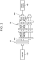
- the gasoline vehicle shown in FIG. 2 includes an engine 110, a clutch 20, and a transmission 30.
- power is transmitted from the engine 110 to the drive wheel 40 via the clutch 20 and the transmission 30.
- the electrified vehicle shown in FIG. 1 is manufactured by replacing the engine 110 of the gasoline vehicle shown in FIG. 2 with the motor 10. Therefore, in the electrified vehicle shown in FIG. 1 , power is transmitted from the motor 10 to the drive wheel 40 via the clutch 20 and the transmission 30.
- the motor 10 includes an output shaft 10a.
- the transmission 30 includes an input shaft 30a and an output shaft 30b.
- the output shaft 10a of the motor 10 is connected to the input shaft 30a of the transmission 30 via the clutch 20.
- the clutch 20 When the clutch 20 is engaged, power is allowed to be transmitted from the output shaft 10a of the motor 10 to the input shaft 30a of the transmission 30.
- the clutch 20 When the clutch 20 is disengaged, power is not allowed to be transmitted from the output shaft 10a of the motor 10 to the input shaft 30a of the transmission 30.
- the clutch 20 is operated by a driver.
- the transmission 30 has a plurality of gear stages. Power is transmitted from the input shaft 30a to the output shaft 30b through the gear stage.
- the transmission 30 changes the rotation ratio of the input shaft 30a to the output shaft 30b (i.e., the speed ratio) by changing the gear stage for transmitting power from the input shaft 30a to the output shaft 30b.
- the gear stage of the transmission 30 is changed by the driver operating a shift lever. That is, the transmission 30 is a so-called manual transmission.
- the output shaft 30b of the transmission 30 is connected to the drive wheel 40 via a pinion gear, a ring gear, a drive shaft, etc., not shown.
- the electrified vehicle shown in FIG. 1 includes a control circuit 50 configured to control the motor 10, and a rotational speed sensor 60 configured to detect the rotational speed (unit: rpm) of the motor 10.
- the control circuit 50 includes an electronic control unit (ECU) 52 and an inverter 54.
- the inverter 54 supplies alternating current (AC) power to the motor 10. That is, the motor 10 is an AC motor that is driven by AC power.
- the ECU 52 controls the inverter 54 to control the frequency and amplitude of the AC power to be supplied from the inverter 54 to the motor 10. The rotational speed and drive torque of the motor 10 are thus controlled.
- the rotational speed sensor 60 detects the rotational speed of the output shaft 10a of the motor 10.
- the detection values from sensors included in the original gasoline vehicle e.g., a sensor configured to detect the state of the clutch 20, a sensor configured to detect the gear stage of the transmission 30, and a sensor configured to detect the rotational speed of the output shaft 30b of the transmission 30
- the ECU 52 detects the state of the drive system based on the rotational speed of the motor 10 detected by the rotational speed sensor 60.
- Drive systems i.e., the clutch 20, the transmission 30, etc.
- the ECU 52 learns the characteristics of the drive system during a shift change, and controls the rotational speed of the motor 10 during a shift change according to the learning results.
- a process that is performed by the ECU 52 during a shift change will be described.
- the ECU 52 estimates the gear stage at the time of starting of the electrified vehicle to be first gear. As will be described in detail later, when a shift change is performed, the ECU 52 determines whether the shift change is an upshift or a downshift. When the ECU 52 determines that the shift change is an upshift, the ECU 52 estimates that the gear stage has been shifted up by one stage. When the ECU 52 determines that the shift change is a downshift, the ECU 52 estimates that the gear stage has been shifted down by one stage. The ECU 52 thus always identifies the current gear stage while the electrified vehicle is traveling.
- the ECU 52 has a storage area.
- the ECU 52 stores shift characteristics and torsional characteristics of the drive system in the storage area.
- the shift characteristics are an index of how much the rotational speed of the input shaft 30a of the transmission 30 changes during a shift change.
- the ECU 52 stores shift characteristics for each of combinations of gear stages before and after a shift change.
- the shift characteristics will be described in detail later.
- the torsional characteristics are characteristics representing fluctuations of the rotational speed of the motor 10 that occur during a shift change.
- the ECU 52 stores torsional characteristics for each of the combinations of gear stages before and after a shift change. The torsional characteristics will be described in detail later.
- the shift characteristics and torsional characteristics to be stored in the storage area are acquired by the ECU 52 performing a learning process. Therefore, when the ECU 52 has not yet learned the shift characteristics and the torsional characteristics, empty values (i.e., NULL values) are stored in the storage area of the ECU 52 as the shift characteristics and the torsional characteristics.
- empty values i.e., NULL values
- FIGS. 4 and 5 show a process that is performed by the ECU 52 during a shift change.
- the ECU 52 determines whether the clutch 20 is disengaged.
- the ECU 52 repeatedly performs step S2 while the electrified vehicle is traveling.
- the ECU 52 detects whether the clutch 20 is disengaged based on the ratio between the torque command value for the motor 10 and the amount of change in rotational speed of the motor 10 detected by the rotational speed sensor 60. That is, when the clutch 20 is disengaged, the motor 10 is disconnected from the drive wheel 40, and therefore the rotational speed of the motor 10 tends to change.
- step S2 the ECU 52 determines that the clutch 20 is disengaged when a value obtained by dividing the amount of change in rotational speed of the motor 10 by the torque command value is equal to or larger than a reference value.
- the driver changes the gear stage of the transmission 30 after disengaging the clutch 20.
- the rotational speed of the input shaft 30a of the transmission 30 changes. That is, the rotational speed of the input shaft 30a of the transmission 30 increases in the case of a downshift.
- the rotational speed of the input shaft 30a of the transmission 30 decreases in the case of an upshift.
- the driver engages the clutch 20 after changing the gear stage.
- the clutch 20 is engaged with the difference between the rotational speed of the motor 10 (i.e., the rotational speed of the output shaft 10a of the motor 10) and the rotational speed of the input shaft 30a of the transmission 30 being large, a large shift shock occurs.
- the ECU 52 can perform a process of reducing the difference between the rotational speed of the motor 10 and the rotational speed of the input shaft 30a of the transmission 30 during the period from when the clutch 20 is disengaged to when the clutch 20 is engaged.
- the ECU 52 can also perform damping control for reducing fluctuations after the clutch 20 is engaged.
- the process that is performed by the ECU 52 varies depending on whether the ECU 52 has learned the shift characteristics and the torsional characteristics.
- FIGS. 6 and 7 show changes in rotational speed of the motor 10 during a shift change when the ECU 52 has not yet learned the shift characteristics and the torsional characteristics.
- time t1 is when the ECU 52 determines in step S2 that the clutch 20 is disengaged.
- step S4 the ECU 52 detects the rotational speed of the motor 10 at time t1 when the clutch 20 is disengaged (hereinafter referred to as the "rotational speed r1") by the rotational speed sensor 60.
- the ECU 52 stores the rotational speed r1.
- the ECU 52 determines in steps S6 to S12 whether the shift change is an upshift or a downshift.
- step S6 the ECU 52 determines whether the electrified vehicle is decelerating.
- the ECU 52 determines whether the electrified vehicle is decelerating, based on the rate of change dr/dt of the rotational speed of the motor 10 when the clutch 20 is disengaged. That is, when the rate of change dr/dt is a negative value, the electrified vehicle is decelerating. Therefore, the ECU 52 determines YES in step S6. For example, in FIG. 6 , the rotational speed of the motor 10 is decreasing at time t1. The ECU 52 therefore determines YES in step S6.
- step S6 When the rate of change dr/dt is a positive value or zero, the electrified vehicle is accelerating or traveling at a constant speed. Therefore, the ECU 52 determines NO in step S6. For example, in FIG. 7 , the rotational speed of the motor 10 is increasing at time t1. The ECU 52 therefore determines NO in step S6.
- step S6 the ECU 52 determines in step S12 that the shift change is a downshift.
- step S8 determines in step S8 whether requested torque input to the ECU 52 is equal to or higher than a reference value (a first reference value).
- the requested torque input to the ECU 52 varies depending on the amount of depression of an accelerator pedal operated by the driver. In a normal shift change, the requested torque is low because the driver does not depress the accelerator pedal. However, in a technique called throttle blipping, the driver depresses the accelerator pedal simultaneously with the shift change. In this case, the requested torque increases to the reference value or higher during the shift change.
- step S8 the ECU 52 determines whether the driver is blipping the throttle by determining whether the requested torque is equal to or higher than the reference value.
- step S8 determines in step S12 that the shift change is a downshift.
- step S10 determines in step S10 that the shift change is an upshift.
- the ECU 52 determines that the shift change is a downshift, regardless of whether the driver is blipping the throttle.
- the ECU 52 determines that the shift change is a downshift.
- the ECU 52 determines that the shift change is an upshift.
- step S12 When the ECU 52 determines in step S12 that the shift change is a downshift, the ECU 52 starts torque-up control in step S16. That is, the ECU 52 increases the torque command value for the motor 10 to increase the rotational speed of the motor 10. For example, in FIG. 6 , the ECU 52 increases the torque command value at or after time t1 when the clutch 20 is disengaged. The rotational speed of the motor 10 therefore increases at or after time t1. When the driver is blipping the throttle, the ECU 52 increases the torque command value to a higher value to increase the rotational speed of the motor 10 faster. The ECU 52 continues to perform the torque-up control until step S22 or S24 that will be described later.
- step S10 When the ECU 52 determines in step S10 that the shift change is an upshift, the ECU 52 starts torque-down control in step S14. That is, the ECU 52 reduces the torque command value for the motor 10 to reduce the rotational speed of the motor 10. For example, in FIG. 7 , the ECU 52 reduces the torque command value at or after time t1 when the clutch 20 is disengaged. The rotational speed of the motor 10 therefore decreases at or after time t1. The ECU 52 continues to perform the torque-down control until step S22 or S24.
- the ECU 52 identifies the gear stage after the shift change in step S18. As described above, the ECU 52 identifies the gear stage before the shift change. When the shift change is an upshift, the ECU 52 identifies the gear stage that is one stage higher than the gear stage before the shift change, as the gear stage after the shift change. When the shift change is a downshift, the ECU 52 identifies the gear stage that is one stage lower than the gear stage before the shift change, as the gear stage after the shift change. In step S18, the combination of gear stages before and after the current shift change is thus identified.
- the combination of gear stages before and after a shift change is sometimes referred to as the "type of shift change.”
- step S20 the ECU 52 determines whether the ECU 52 has learned the shift characteristics corresponding to the type of shift change identified in step S18. That is, the ECU 52 accesses the data set regarding shift characteristics illustrated in FIG. 3 and determines whether the ECU 52 has learned the shift characteristics corresponding to the type of shift change identified in step S18. When the ECU 52 has learned the shift characteristics corresponding to the type of shift change identified in step S18, the ECU 52 determines YES in step S20. When the ECU 52 has not yet learned the shift characteristics corresponding to the type of shift change identified in step S18, the ECU 52 determines NO in step S20. In the examples of FIGS.
- step S24 the ECU 52 monitors the rotational speed of the motor 10, and ends the torque-up control or the torque-down control as soon as the rotational speed of the motor 10 changes by a predetermined amount. For example, in FIG. 6 , the ECU 52 ends the torque-up control at time t2 when the rotational speed of the motor 10 has increased by a predetermined amount ⁇ rx. For example, in FIG. 7 , the ECU 52 ends the torque-down control at time t2 when the rotational speed of the motor 10 has decreased by the predetermined amount ⁇ rx. After the ECU 52 ends the torque-up control or the torque-down control, the ECU 52 controls the motor 10 to keep the rotational speed of the motor 10 constant.
- the rotational speed r2 indicates the rotational speed of the motor 10 after the torque-up control or the torque-down control.
- the rotational speed rh indicates the actual rotational speed of the input shaft 30a of the transmission 30 after the gear stage is changed.
- the ECU 52 changes the rotational speed of the motor 10 by the predetermined amount ⁇ rx when the ECU 52 has not yet learned the shift characteristics. Therefore, the rotational speed r2 cannot be accurately matched to the rotational speed rh.
- the ECU 52 monitors the ratio between the amount of change in rotational speed of the motor 10 and the torque command value in a manner similar to that in step S2.
- the value obtained by dividing the amount of change in rotational speed of the motor 10 by the torque command value decreases to a value less than the reference value.
- the ECU 52 therefore determines in step S26 that the clutch 20 is engaged. For example, in FIGS. 6 and 7 , the clutch 20 is engaged at time t3.
- step S28 the ECU 52 determines whether the ECU 52 has learned the torsional characteristics corresponding to the type of shift change identified in step S18. That is, the ECU 52 accesses the data set regarding torsional characteristics illustrated in FIG. 3 and determines whether the ECU 52 has learned the torsional characteristics corresponding to the type of shift change identified in step S 18.
- the ECU 52 determines NO in step S28 and skips steps S30, S32. That is, when the ECU 52 has not yet learned the torsional characteristics corresponding to the type of shift change identified in step S18, the ECU 52 does not perform the damping control in step S32.
- the rotational speed r2 of the motor 10 cannot be accurately matched to the rotational speed rh of the input shaft 30a of the transmission 30 after the gear stage is changed. Moreover, when the ECU 52 has not yet learned the torsional characteristics, the ECU 52 does not perform the damping control after the clutch 20 is engaged. Therefore, a large shift shock occurs immediately after the clutch 20 is engaged. For example, in FIGS. 6 and 7 , the rotational speed of the motor 10 fluctuates greatly during a period T1 immediately after time t3 when the clutch 20 is engaged. The rotational speed of the motor 10 also changes greatly before and after the period T1 during which the rotational speed of the motor 10 fluctuates. For example, in FIG.
- the ECU 52 monitors the rotational speed of the motor 10 after the clutch 20 is engaged.
- the ECU 52 performs steps S34, S36 at time t4 when the fluctuations of the rotational speed of the motor 10 settle down.
- step S34 the ECU 52 stores the fluctuation waveform of the rotational speed of the motor 10 generated during the period T1, as the torsional characteristics.
- the ECU 52 stores the detected fluctuation waveform as the torsional characteristics corresponding to the type of shift change identified in step S 18.
- step S36 the ECU 52 detects the rotational speed r3 of the motor 10 at time t4. Thereafter, in step S38, the ECU 52 calculates the rate of change r3/r1 of the rotational speed of the motor 10 before and after the shift change by dividing the rotational speed r3 by the rotational speed r1.
- the rotational speed r1 of the motor 10 before the shift change is equal to the rotational speed of the input shaft 30a of the transmission 30 before the shift change.
- the rotational speed r3 of the motor 10 after the shift change is equal to the rotational speed of the input shaft 30a of the transmission 30 after the shift change.
- the rate of change r3/r1 is equal to the rate of change of the rotational speed of the input shaft 30a of the transmission 30 before and after the shift change.
- the ECU 52 stores the rate of change r3/r1 as the shift characteristics.
- the ECU 52 stores the rate of change r3/r1 calculated in step S38 as the shift characteristics corresponding to the type of shift change identified in step S18.
- the rotational speed r3 of the motor 10 after the shift change is equal to the rotational speed rh of the input shaft 30a of the transmission 30 after the shift change
- a predicted value of the rotational speed rh of the input shaft 30a of the transmission 30 after the shift change can be calculated by multiplying the rate of change r3/r1 by the rotational speed of the motor 10 before the shift change.
- the shift characteristics are thus a value that allows prediction of the rotational speed rh of the input shaft 30a after the shift change.
- the shift characteristics are the rate of change r3/r1.
- the shift characteristics may be a function, database, etc. that allows the predicted value of the rotational speed rh of the input shaft 30a after the shift change to be calculated based on the type of shift change and the rotational speed of the motor 10 at the start of the shift change.
- the shift characteristics may be a function, database, etc. that allows the predicted value of the rotational speed rh of the input shaft 30a after the shift change to be calculated based on the rotational speed of the motor 10 at the start of the shift change.
- the ECU 52 learns the shift characteristics and the torsional characteristics.
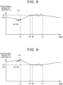
- FIGS. 8 and 9 illustrate changes in rotational speed of the motor 10 during a shift change when the ECU 52 has learned the shift characteristics and the torsional characteristics.
- the ECU 52 detects at time t1 that the clutch 20 is disengaged, detects the rotational speed of the motor 10 at time t1 (hereinafter referred to as the "rotational speed r11"), and performs the torque-down control or the torque-up control at or after time t1.
- step S20 the ECU 52 determines YES in step S20.
- the ECU 52 then performs step S22.
- step S22 the ECU 52 reads from the storage area the shift characteristics corresponding to the type of shift change identified in step S 18.
- the ECU 52 performs the torque-up control or the torque-down control until the rotational speed of the motor 10 becomes equal to the control target value rt.
- the ECU 52 controls the rotational speed of the motor 10 so that the rotational speed of the motor 10 remains equal to the control target value rt. Therefore, the rotational speed of the motor 10 is substantially equal to the control target value rt immediately after time t5.
- the control target value rt for the motor 10 is maintained until the shift change is completed (i.e., time t7 in FIGS. 8 and 9 ).
- step S26 the ECU 52 detects that the clutch 20 is engaged.
- the clutch 20 is engaged at time t6.
- the rotational speed of the motor 10 fluctuates.
- the rotational speed of the motor 10 is controlled to the control target value rt that is substantially equal to the rotational speed rh of the input shaft 30a of the transmission 30 after the shift change. Therefore, in FIGS. 8 and 9 , the rotational speed of the motor 10 fluctuates slightly after the clutch 20 is engaged, and the rotational speed of the motor 10 changes slightly before and after the fluctuations occur.
- the ECU 52 controls the rotational speed of the motor 10 to a value substantially equal to the rotational speed rh before the clutch 20 is engaged. Therefore, a shift shock is small.
- step S26 When the ECU 52 detects in step S26 that the clutch 20 is engaged, the ECU 52 performs the damping control as necessary in steps S28 to S32.
- step S28 When the ECU 52 has learned the torsional characteristics corresponding to the type of shift change identified in step S 18, the ECU 52 determines YES in step S28 and performs step S30.
- the ECU 52 determines NO in step S30 and does not perform the damping control.
- the ECU 52 determines YES in step S30 and performs the damping control in step S32.
- FIG. 10 shows a predicted value of the fluctuations of the rotational speed of the motor 10 and a torque command value ts for the motor 10 in the damping control.
- the ECU 52 reads from the storage area the torsional characteristics corresponding to the type of shift change identified in step S 18, and calculates a predicted value of the fluctuations that will occur after time t6x.
- the frequency of the fluctuations that will occur after the clutch 20 is engaged is determined by the structure of the drive system (e.g., the resonance frequency of the drive system).
- the ECU 52 can predict the fluctuations that will occur after time t6x from the torsional characteristics (i.e., the fluctuation waveform detected in the learning process). After calculating the predicted value of the fluctuations that will occur after time t6x, the ECU 52 calculates a predicted value of the torque that will be applied to a rotating shaft of the motor 10 due to the fluctuations by, for example, differentiating the calculated predicted value of the fluctuations. The ECU 52 then calculates the torque command value ts so as to cancel the calculated predicted value of the torque. After time t6x, the ECU 52 controls the torque of the motor 10 according to the graph of the calculated torque command value ts. As a result, the fluctuations of the rotational speed of the motor 10 that will occur after the clutch 20 is engaged are reduced. As described above, the fluctuations of the rotational speed of the motor 10 are further reduced by performing the damping control.
- the ECU 52 performs steps S34 to S38.
- the ECU 52 may either skip step S34 (i.e., the learning process for the torsional characteristics) or perform step S34.
- step S34 when the ECU 52 has learned the torsional characteristics sometimes allows more accurate damping control.
- the ECU 52 may either skip steps S36, S38 (i.e., the learning process for the shift characteristics) or perform steps S36, S38.
- steps S36, S38 when the ECU 52 has learned the shift characteristics sometimes allows the rotational speed of the motor 10 to be more accurately matched to the rotational speed of the input shaft 30a of the transmission 30.
- the ECU 52 increases the torque value in the torque-up control to a higher value than when the driver is not blipping the throttle.
- the ECU 52 increases the torque command value for the motor 10 to a higher value at or after time tb when the throttle blipping is detected.
- the rotational speed of the motor 10 increases faster at or after time tb. Therefore, the rotational speed of the motor 10 can be more quickly controlled to the control target value rt. Accordingly, when the driver is blipping the throttle, a shift change can be more quickly performed with a small shift shock.
- the ECU 52 estimates that the gear stage has been changed by one stage at each shift change.
- the driver may upshift from second gear to fourth gear or may downshift from fourth gear to second gear.
- the control target value rt becomes a value significantly different from the actual rotational speed rh of the input shaft 30a, and the rotational speed of the motor 10 may significantly increase or decrease immediately after time t6 when the clutch 20 is engaged.
- the ECU 52 maintains the control target value rt as the target value of the rotational speed of the motor 10 in this case, the behavior of the motor 10 may become abnormal.
- the ECU 52 may stop the control of keeping the rotational speed of the motor 10 at the control target value rt.
- the ECU 52 learns the torsional characteristics for each type of shift change. However, when the torsional characteristics are almost the same among the types of shift change, the ECU 52 may learn one kind of torsional characteristics (i.e., common torsional characteristics). In this case, damping control based on common torsional characteristics can be performed for all types of shift change.
- common torsional characteristics i.e., common torsional characteristics
- Steps S36, S38 are an example of the learning process of detecting the first rotational speed and the second rotational speed.
- Step S22 is an example of the control process of changing the rotational speed of the motor based on the first rotational speed and the second rotational speed.
- Step S34 is an example of the learning process of detecting the fluctuation waveform.
- Step S32 is an example of the control process of controlling the motor so as to reduce the fluctuations of the rotational speed of the motor based on the fluctuation waveform.
- Time t1 is an example of the first time.
- Time t4 is an example of the second time.
- Time t6 is an example of the third time.
Landscapes
- Engineering & Computer Science (AREA)
- Mechanical Engineering (AREA)
- Transportation (AREA)
- Chemical & Material Sciences (AREA)
- Combustion & Propulsion (AREA)
- General Engineering & Computer Science (AREA)
- Power Engineering (AREA)
- Automation & Control Theory (AREA)
- Control Of Transmission Device (AREA)
- Electric Propulsion And Braking For Vehicles (AREA)
Abstract
An electrified vehicle includes a motor (10), a clutch (20), a transmission (30), a rotational speed sensor (60) configured to detect a rotational speed of the motor (10), and a control circuit (50) configured to control the motor (10). The control circuit (50) performs: a learning process of detecting a change in the rotational speed of the motor (10) by the rotational speed sensor (60) when the shift change is performed; and a control process of controlling the rotational speed of the motor (10) based on the change in the rotational speed detected in the learning process, when the shift change is performed after the learning process.
Description
- The technique disclosed in the present specification relates to electrified vehicles and methods for manufacturing the same.
- An electrified vehicle disclosed in
WO2013/061359 includes a motor, a clutch, and a transmission. An input shaft of the transmission is connected to the motor through the clutch. An output shaft of the transmission transmits power to a drive wheel. The transmission changes a gear stage for transmitting power from the input shaft to the output shaft. The electrified vehicle includes a control circuit that controls the rotational speed of the motor during a shift change. The control circuit reduces a shift shock by controlling the rotational speed of the motor during the shift change. - In the technique disclosed in
WO2013/061359 , a target rotational speed of the motor during a shift change is set to an appropriate rotational speed, and the control circuit reduces a shift shock by controlling the rotational speed of the motor to the target rotational speed during the shift change. Therefore, the technique ofWO2013/061359 cannot be used when an appropriate rotational speed is not known. For example, electrified vehicles are sometimes manufactured by replacing engines of various gasoline vehicles (e.g., used gasoline vehicles) with motors. In this case, an appropriate rotational speed that can reduce a shift shock varies depending on the structure of the original gasoline vehicle, and it is difficult to set the target rotational speed in the control circuit. The present disclosure proposes a technique of reducing a shift shock when an appropriate rotational speed is not known. - An electrified vehicle according to one aspect of the present disclosure includes a motor, a clutch, a transmission, a rotational speed sensor, and a control circuit. The transmission includes an input shaft and an output shaft. The input shaft is connected to the motor through the clutch. The output shaft transmits power to a drive wheel. The transmission changes a gear stage for transmitting the power from the input shaft to the output shaft. The rotational speed sensor detects a rotational speed of the motor. The control circuit controls the motor. The electrified vehicle is configured to perform a shift change in which the gear stage is changed after the clutch is disengaged and the clutch is engaged after the gear stage is changed. The control circuit is configured to perform: a learning process of detecting a change in the rotational speed of the motor by the rotational speed sensor when the shift change is performed; and a control process of controlling the rotational speed of the motor based on the change in the rotational speed detected in the learning process, when the shift change is performed after the learning process.
- In the electrified vehicle according to the above aspect, the control circuit performs the learning process of detecting a change in the rotational speed of the motor by the rotational speed sensor when the shift change is performed. By detecting a change in the rotational speed of the motor during the shift change, the rotational speed of the motor that can reduce a shift shock can be calculated. The control circuit controls the rotational speed of the motor based on the change in the rotational speed detected in the learning process, when the shift change is performed after the learning process. Accordingly, the control circuit can appropriately control the rotational speed of the motor to reduce a shift shock.
- Features, advantages, and technical and industrial significance of exemplary embodiments of the invention will be described below with reference to the accompanying drawings, in which like signs denote like elements, and wherein:
-
FIG. 1 is a block diagram of a drive system of an electrified vehicle; -
FIG. 2 is a block diagram of a drive system of a gasoline vehicle that is used to manufacture the electrified vehicle; -
FIG. 3 is a table showing shift characteristics and torsional characteristics stored in an electronic control unit (ECU); -
FIG. 4 is a flowchart showing the first half of a process that is performed by the ECU during a shift change; -
FIG. 5 is a flowchart showing the second half of the process that is performed by the ECU during a shift change; -
FIG. 6 is a graph showing the rotational speed of a motor during a downshift when the ECU has not yet learned the shift characteristics and the torsional characteristics; -
FIG. 7 is a graph showing the rotational speed of the motor during an upshift when the ECU has not yet learned the shift characteristics and the torsional characteristics; -
FIG. 8 is a graph showing the rotational speed of the motor during a downshift when the ECU has learned the shift characteristics and the torsional characteristics; -
FIG. 9 is a graph showing the rotational speed of the motor during an upshift when the ECU has learned the shift characteristics and the torsional characteristics; -
FIG. 10 is a graph showing a predicted value of fluctuations and a torque command value in damping control; and -
FIG. 11 is a graph showing the rotational speed of the motor during throttle blipping. - In an example of an electrified vehicle disclosed in the present specification, in the learning process, the control circuit may detect a first rotational speed and a second rotational speed, the first rotational speed being a rotational speed of the motor at first time, the second rotational speed being a rotational speed of the motor at second time, the first time being when the clutch is disengaged, and the second time being when fluctuations of the rotational speed of the motor that occur after the clutch is engaged settle down. In the control process, the control circuit may change the rotational speed of the motor in a period from the first time to third time based on the first rotational speed and the second rotational speed, the third time being when the clutch is engaged.
- With this configuration, the difference between the rotational speed of the motor and the rotational speed of the input shaft of the transmission when the clutch is engaged can be reduced. A shift shock can therefore be suitably reduced.
- In the example of the electrified vehicle disclosed in the present specification, when the shift change in the control process is an upshift, the control circuit may reduce the rotational speed of the motor within the period from the first time to the third time. When the shift change in the control process is a downshift, the control circuit may increase the rotational speed of the motor within the period from the first time to the third time.
- With this configuration, a shift shock can be suitably reduced.
- In the example of the electrified vehicle disclosed in the present specification, when the shift change in the control process is the downshift, the control circuit may increase the rotational speed of the motor faster when requested torque for the motor after the clutch is disengaged is equal to or higher than a first reference value than when the requested torque for the motor after the clutch is disengaged is less than the first reference value.
- With this configuration, when the requested torque is equal to or higher than the first reference value, the rotational speed of the motor can be quickly increased to an appropriate value, and a downshift can be quickly performed with a small shift shock.
- In the example of the electrified vehicle disclosed in the present specification, in the control process, the control circuit may perform rotational speed control of keeping a target rotational speed of the motor constant from the third time to the second time, and may stop the rotational speed control when the rotational speed of the motor detected by the rotational speed sensor after the third time changes with a gradient equal to or greater than a second reference value.
- With this configuration, the rotational speed control can be stopped when the rotational speed of the motor does not match the rotational speed of the input shaft of the transmission during the rotational speed control.
- In the example of the electrified vehicle disclosed in the present specification, in the learning process, the control circuit may detect a fluctuation waveform of the rotational speed of the motor generated after the clutch is engaged. In the control process, the control circuit may control the motor so as to reduce fluctuations of the rotational speed of the motor that are going to occur after the clutch is engaged, based on the fluctuation waveform detected in the learning process.
- With this configuration, the fluctuations of the rotational speed of the motor can be reduced after the clutch is engaged.
- In the example of the electrified vehicle disclosed in the present specification, the control circuit may store in a storage area the change in the rotational speed for each of combinations of the gear stages before and after the shift change. In the control process, the control circuit may estimate a combination of the gear stages before and after the shift change, read the change in the rotational speed corresponding to the estimated combination from the storage area, and control the rotational speed of the motor based on the read change in the rotational speed.
- With this configuration, the rotational speed of the motor can be appropriately controlled according to the combination of the gear stages before and after the shift change.
- In the example of the electrified vehicle disclosed in the present specification, the control circuit may estimate that the gear stage when the electrified vehicle is started is first gear. When the shift change is an upshift, the control circuit may estimate that the gear stage has been shifted up by one stage. When the shift change is a downshift, the control circuit may estimate that the gear stage has been shifted down by one stage.
- With this configuration, the gear stage can be estimated without using a sensor for detecting the gear stage.
- In the example of the electrified vehicle disclosed in the present specification, the control circuit may determine whether the shift change is the upshift or the downshift based on a gradient of the change in the rotational speed of the motor before the clutch is disengaged.
- With this configuration, whether the shift change is an upshift or a downshift can be detected without using a sensor for detecting the gear stage.
- In the example of the electrified vehicle disclosed in the present specification, the control circuit may determine whether the shift change is the upshift or the downshift based on a gradient of the change in the rotational speed of the motor before the clutch is disengaged and the requested torque for the motor after the clutch is disengaged.
- With this configuration, whether the shift change is an upshift or a downshift can be detected without using a sensor for detecting the gear stage.
- In the example of the electrified vehicle disclosed in the present specification, the control circuit may determine whether the clutch is engaged or disengaged based on a ratio between an amount of change in the rotational speed of the motor detected by the rotational speed sensor and drive torque of the motor.
- With this configuration, whether the clutch is engaged or disengaged can be detected without using a sensor for detecting the state of the clutch.
- The present specification proposes a method for manufacturing the above electrified vehicle. This method includes preparing a vehicle including an engine connected to the input shaft of the transmission through the clutch; and replacing the engine of the vehicle with the motor.
- In an electrified vehicle manufactured by this method, the rotational speed at which a shift shock is less likely to occur varies depending on the characteristics of a drive system of the original vehicle. A shift shock can be reduced by mounting the control circuit that performs the learning process and the control process on the vehicle manufactured by this method.
-
FIG. 1 shows a drive system of an electrified vehicle according to an embodiment. The electrified vehicle shown inFIG. 1 travels when amotor 10 drives adrive wheel 40. The electrified vehicle shown inFIG. 1 is a vehicle manufactured using a gasoline vehicle shown inFIG. 2 . The gasoline vehicle shown inFIG. 2 includes anengine 110, a clutch 20, and atransmission 30. In the gasoline vehicle shown inFIG. 2 , power is transmitted from theengine 110 to thedrive wheel 40 via the clutch 20 and thetransmission 30. The electrified vehicle shown inFIG. 1 is manufactured by replacing theengine 110 of the gasoline vehicle shown inFIG. 2 with themotor 10. Therefore, in the electrified vehicle shown inFIG. 1 , power is transmitted from themotor 10 to thedrive wheel 40 via the clutch 20 and thetransmission 30. - The
motor 10 includes anoutput shaft 10a. Thetransmission 30 includes aninput shaft 30a and anoutput shaft 30b. Theoutput shaft 10a of themotor 10 is connected to theinput shaft 30a of thetransmission 30 via the clutch 20. When the clutch 20 is engaged, power is allowed to be transmitted from theoutput shaft 10a of themotor 10 to theinput shaft 30a of thetransmission 30. When the clutch 20 is disengaged, power is not allowed to be transmitted from theoutput shaft 10a of themotor 10 to theinput shaft 30a of thetransmission 30. The clutch 20 is operated by a driver. Thetransmission 30 has a plurality of gear stages. Power is transmitted from theinput shaft 30a to theoutput shaft 30b through the gear stage. Thetransmission 30 changes the rotation ratio of theinput shaft 30a to theoutput shaft 30b (i.e., the speed ratio) by changing the gear stage for transmitting power from theinput shaft 30a to theoutput shaft 30b. The gear stage of thetransmission 30 is changed by the driver operating a shift lever. That is, thetransmission 30 is a so-called manual transmission. Theoutput shaft 30b of thetransmission 30 is connected to thedrive wheel 40 via a pinion gear, a ring gear, a drive shaft, etc., not shown. - The electrified vehicle shown in
FIG. 1 includes acontrol circuit 50 configured to control themotor 10, and arotational speed sensor 60 configured to detect the rotational speed (unit: rpm) of themotor 10. Thecontrol circuit 50 includes an electronic control unit (ECU) 52 and aninverter 54. Theinverter 54 supplies alternating current (AC) power to themotor 10. That is, themotor 10 is an AC motor that is driven by AC power. TheECU 52 controls theinverter 54 to control the frequency and amplitude of the AC power to be supplied from theinverter 54 to themotor 10. The rotational speed and drive torque of themotor 10 are thus controlled. Therotational speed sensor 60 detects the rotational speed of theoutput shaft 10a of themotor 10. - Since various gasoline vehicle standards are used to manufacture electrified vehicles, the detection values from sensors included in the original gasoline vehicle (e.g., a sensor configured to detect the state of the clutch 20, a sensor configured to detect the gear stage of the
transmission 30, and a sensor configured to detect the rotational speed of theoutput shaft 30b of the transmission 30) cannot be input to theECU 52. Therefore, theECU 52 detects the state of the drive system based on the rotational speed of themotor 10 detected by therotational speed sensor 60. Drive systems (i.e., the clutch 20, thetransmission 30, etc.) of gasoline vehicles that are used to manufacture electrified vehicles have various characteristics during a shift change. Therefore, in the electrified vehicle shown inFIG. 1 , theECU 52 learns the characteristics of the drive system during a shift change, and controls the rotational speed of themotor 10 during a shift change according to the learning results. Hereinafter, a process that is performed by theECU 52 during a shift change will be described. - The
ECU 52 estimates the gear stage at the time of starting of the electrified vehicle to be first gear. As will be described in detail later, when a shift change is performed, theECU 52 determines whether the shift change is an upshift or a downshift. When theECU 52 determines that the shift change is an upshift, theECU 52 estimates that the gear stage has been shifted up by one stage. When theECU 52 determines that the shift change is a downshift, theECU 52 estimates that the gear stage has been shifted down by one stage. TheECU 52 thus always identifies the current gear stage while the electrified vehicle is traveling. - The
ECU 52 has a storage area. TheECU 52 stores shift characteristics and torsional characteristics of the drive system in the storage area. The shift characteristics are an index of how much the rotational speed of theinput shaft 30a of thetransmission 30 changes during a shift change. For example, as shown inFIG. 3 , theECU 52 stores shift characteristics for each of combinations of gear stages before and after a shift change. The shift characteristics will be described in detail later. The torsional characteristics are characteristics representing fluctuations of the rotational speed of themotor 10 that occur during a shift change. For example, as shown inFIG. 3 , theECU 52 stores torsional characteristics for each of the combinations of gear stages before and after a shift change. The torsional characteristics will be described in detail later. The shift characteristics and torsional characteristics to be stored in the storage area are acquired by theECU 52 performing a learning process. Therefore, when theECU 52 has not yet learned the shift characteristics and the torsional characteristics, empty values (i.e., NULL values) are stored in the storage area of theECU 52 as the shift characteristics and the torsional characteristics. -
FIGS. 4 and5 show a process that is performed by theECU 52 during a shift change. In step S2, theECU 52 determines whether the clutch 20 is disengaged. TheECU 52 repeatedly performs step S2 while the electrified vehicle is traveling. In step S2, theECU 52 detects whether the clutch 20 is disengaged based on the ratio between the torque command value for themotor 10 and the amount of change in rotational speed of themotor 10 detected by therotational speed sensor 60. That is, when the clutch 20 is disengaged, themotor 10 is disconnected from thedrive wheel 40, and therefore the rotational speed of themotor 10 tends to change. Therefore, even when the torque command value is the same, the amount of change in rotational speed of themotor 10 is much larger when the clutch 20 is disengaged than when the clutch 20 is engaged. In step S2, theECU 52 determines that the clutch 20 is disengaged when a value obtained by dividing the amount of change in rotational speed of themotor 10 by the torque command value is equal to or larger than a reference value. - The driver changes the gear stage of the
transmission 30 after disengaging the clutch 20. When the gear stage is changed, the rotational speed of theinput shaft 30a of thetransmission 30 changes. That is, the rotational speed of theinput shaft 30a of thetransmission 30 increases in the case of a downshift. The rotational speed of theinput shaft 30a of thetransmission 30 decreases in the case of an upshift. The driver engages the clutch 20 after changing the gear stage. When the clutch 20 is engaged with the difference between the rotational speed of the motor 10 (i.e., the rotational speed of theoutput shaft 10a of the motor 10) and the rotational speed of theinput shaft 30a of thetransmission 30 being large, a large shift shock occurs. Therefore, theECU 52 can perform a process of reducing the difference between the rotational speed of themotor 10 and the rotational speed of theinput shaft 30a of thetransmission 30 during the period from when the clutch 20 is disengaged to when the clutch 20 is engaged. TheECU 52 can also perform damping control for reducing fluctuations after the clutch 20 is engaged. The process that is performed by theECU 52 varies depending on whether theECU 52 has learned the shift characteristics and the torsional characteristics. - First, an example in which the
ECU 52 has not yet learned the shift characteristics and the torsional characteristics will be described.FIGS. 6 and 7 show changes in rotational speed of themotor 10 during a shift change when theECU 52 has not yet learned the shift characteristics and the torsional characteristics. InFIGS. 6 and 7 , time t1 is when theECU 52 determines in step S2 that the clutch 20 is disengaged. - When the
ECU 52 determines that the clutch 20 is disengaged, theECU 52 performs step S4. In step S4, theECU 52 detects the rotational speed of themotor 10 at time t1 when the clutch 20 is disengaged (hereinafter referred to as the "rotational speed r1") by therotational speed sensor 60. TheECU 52 stores the rotational speed r1. - Next, the
ECU 52 determines in steps S6 to S12 whether the shift change is an upshift or a downshift. - In step S6, the
ECU 52 determines whether the electrified vehicle is decelerating. In this example, theECU 52 determines whether the electrified vehicle is decelerating, based on the rate of change dr/dt of the rotational speed of themotor 10 when the clutch 20 is disengaged. That is, when the rate of change dr/dt is a negative value, the electrified vehicle is decelerating. Therefore, theECU 52 determines YES in step S6. For example, inFIG. 6 , the rotational speed of themotor 10 is decreasing at time t1. TheECU 52 therefore determines YES in step S6. When the rate of change dr/dt is a positive value or zero, the electrified vehicle is accelerating or traveling at a constant speed. Therefore, theECU 52 determines NO in step S6. For example, inFIG. 7 , the rotational speed of themotor 10 is increasing at time t1. TheECU 52 therefore determines NO in step S6. - When YES in step S6, the
ECU 52 determines in step S12 that the shift change is a downshift. - When NO in step S6, the
ECU 52 determines in step S8 whether requested torque input to theECU 52 is equal to or higher than a reference value (a first reference value). The requested torque input to theECU 52 varies depending on the amount of depression of an accelerator pedal operated by the driver. In a normal shift change, the requested torque is low because the driver does not depress the accelerator pedal. However, in a technique called throttle blipping, the driver depresses the accelerator pedal simultaneously with the shift change. In this case, the requested torque increases to the reference value or higher during the shift change. In step S8, theECU 52 determines whether the driver is blipping the throttle by determining whether the requested torque is equal to or higher than the reference value. When YES in step S8 (i.e., when the driver is blipping the throttle), theECU 52 determines in step S12 that the shift change is a downshift. When NO in step S8 (i.e., when the driver is not blipping the throttle), theECU 52 determines in step S10 that the shift change is an upshift. - As described above, when the electrified vehicle is decelerating, the
ECU 52 determines that the shift change is a downshift, regardless of whether the driver is blipping the throttle. When the electrified vehicle is accelerating or traveling at a constant speed and the driver is blipping the throttle, theECU 52 determines that the shift change is a downshift. When the electrified vehicle is accelerating or traveling at a constant speed and the driver is not blipping the throttle, theECU 52 determines that the shift change is an upshift. - When the
ECU 52 determines in step S12 that the shift change is a downshift, theECU 52 starts torque-up control in step S16. That is, theECU 52 increases the torque command value for themotor 10 to increase the rotational speed of themotor 10. For example, inFIG. 6 , theECU 52 increases the torque command value at or after time t1 when the clutch 20 is disengaged. The rotational speed of themotor 10 therefore increases at or after time t1. When the driver is blipping the throttle, theECU 52 increases the torque command value to a higher value to increase the rotational speed of themotor 10 faster. TheECU 52 continues to perform the torque-up control until step S22 or S24 that will be described later. - When the
ECU 52 determines in step S10 that the shift change is an upshift, theECU 52 starts torque-down control in step S14. That is, theECU 52 reduces the torque command value for themotor 10 to reduce the rotational speed of themotor 10. For example, inFIG. 7 , theECU 52 reduces the torque command value at or after time t1 when the clutch 20 is disengaged. The rotational speed of themotor 10 therefore decreases at or after time t1. TheECU 52 continues to perform the torque-down control until step S22 or S24. - After step S14 or S16, the
ECU 52 identifies the gear stage after the shift change in step S18. As described above, theECU 52 identifies the gear stage before the shift change. When the shift change is an upshift, theECU 52 identifies the gear stage that is one stage higher than the gear stage before the shift change, as the gear stage after the shift change. When the shift change is a downshift, theECU 52 identifies the gear stage that is one stage lower than the gear stage before the shift change, as the gear stage after the shift change. In step S18, the combination of gear stages before and after the current shift change is thus identified. Hereinafter, the combination of gear stages before and after a shift change is sometimes referred to as the "type of shift change." - Next, the
ECU 52 performs step S20. In step S20, theECU 52 determines whether theECU 52 has learned the shift characteristics corresponding to the type of shift change identified in step S18. That is, theECU 52 accesses the data set regarding shift characteristics illustrated inFIG. 3 and determines whether theECU 52 has learned the shift characteristics corresponding to the type of shift change identified in step S18. When theECU 52 has learned the shift characteristics corresponding to the type of shift change identified in step S18, theECU 52 determines YES in step S20. When theECU 52 has not yet learned the shift characteristics corresponding to the type of shift change identified in step S18, theECU 52 determines NO in step S20. In the examples ofFIGS. 6 and 7 , theECU 52 has not yet learned the shift characteristics. Therefore, theECU 52 determines NO in step S20. In this case, theECU 52 performs step S24. In step S24, theECU 52 monitors the rotational speed of themotor 10, and ends the torque-up control or the torque-down control as soon as the rotational speed of themotor 10 changes by a predetermined amount. For example, inFIG. 6 , theECU 52 ends the torque-up control at time t2 when the rotational speed of themotor 10 has increased by a predetermined amount Δrx. For example, inFIG. 7 , theECU 52 ends the torque-down control at time t2 when the rotational speed of themotor 10 has decreased by the predetermined amount Δrx. After theECU 52 ends the torque-up control or the torque-down control, theECU 52 controls themotor 10 to keep the rotational speed of themotor 10 constant. - In
FIGS. 6 and 7 , the rotational speed r2 indicates the rotational speed of themotor 10 after the torque-up control or the torque-down control. The rotational speed rh indicates the actual rotational speed of theinput shaft 30a of thetransmission 30 after the gear stage is changed. As described above, theECU 52 changes the rotational speed of themotor 10 by the predetermined amount Δrx when theECU 52 has not yet learned the shift characteristics. Therefore, the rotational speed r2 cannot be accurately matched to the rotational speed rh. - During the shift change, the
ECU 52 monitors the ratio between the amount of change in rotational speed of themotor 10 and the torque command value in a manner similar to that in step S2. When the driver engages the clutch 20, the value obtained by dividing the amount of change in rotational speed of themotor 10 by the torque command value decreases to a value less than the reference value. TheECU 52 therefore determines in step S26 that the clutch 20 is engaged. For example, inFIGS. 6 and 7 , the clutch 20 is engaged at time t3. - When the
ECU 52 detects that the clutch 20 is engaged, theECU 52 performs step S28. In step S28, theECU 52 determines whether theECU 52 has learned the torsional characteristics corresponding to the type of shift change identified in step S18. That is, theECU 52 accesses the data set regarding torsional characteristics illustrated inFIG. 3 and determines whether theECU 52 has learned the torsional characteristics corresponding to the type of shift change identified instep S 18. When theECU 52 has not yet learned the torsional characteristics corresponding to the type of shift change identified in step S18, theECU 52 determines NO in step S28 and skips steps S30, S32. That is, when theECU 52 has not yet learned the torsional characteristics corresponding to the type of shift change identified in step S18, theECU 52 does not perform the damping control in step S32. - As described above, when the
ECU 52 has not yet learned the shift characteristics, the rotational speed r2 of themotor 10 cannot be accurately matched to the rotational speed rh of theinput shaft 30a of thetransmission 30 after the gear stage is changed. Moreover, when theECU 52 has not yet learned the torsional characteristics, theECU 52 does not perform the damping control after the clutch 20 is engaged. Therefore, a large shift shock occurs immediately after the clutch 20 is engaged. For example, inFIGS. 6 and 7 , the rotational speed of themotor 10 fluctuates greatly during a period T1 immediately after time t3 when the clutch 20 is engaged. The rotational speed of themotor 10 also changes greatly before and after the period T1 during which the rotational speed of themotor 10 fluctuates. For example, inFIG. 6 , when the clutch 20 is engaged at time t3, rotation of theoutput shaft 10a of themotor 10 is affected by rotation of theinput shaft 30a of thetransmission 30. The rotational speed of themotor 10 therefore increases to a rotational speed r3 that is substantially equal to the rotational speed rh of theinput shaft 30a. InFIG. 7 , when the clutch 20 is engaged at time t3, rotation of theoutput shaft 10a of themotor 10 is affected by rotation of theinput shaft 30a of thetransmission 30. The rotational speed of themotor 10 therefore decreases to the rotational speed r3 that is substantially equal to the rotational speed rh of theinput shaft 30a. As described above, when theECU 52 has not yet learned the shift characteristics and the torsional characteristics, the rotational speed of themotor 10 changes greatly after the clutch 20 is engaged. A large shift shock therefore occurs in the electrified vehicle. - The
ECU 52 monitors the rotational speed of themotor 10 after the clutch 20 is engaged. TheECU 52 performs steps S34, S36 at time t4 when the fluctuations of the rotational speed of themotor 10 settle down. - In step S34, the
ECU 52 stores the fluctuation waveform of the rotational speed of themotor 10 generated during the period T1, as the torsional characteristics. In this example, theECU 52 stores the detected fluctuation waveform as the torsional characteristics corresponding to the type of shift change identified instep S 18. - In step S36, the
ECU 52 detects the rotational speed r3 of themotor 10 at time t4. Thereafter, in step S38, theECU 52 calculates the rate of change r3/r1 of the rotational speed of themotor 10 before and after the shift change by dividing the rotational speed r3 by the rotational speed r1. The rotational speed r1 of themotor 10 before the shift change is equal to the rotational speed of theinput shaft 30a of thetransmission 30 before the shift change. The rotational speed r3 of themotor 10 after the shift change is equal to the rotational speed of theinput shaft 30a of thetransmission 30 after the shift change. Therefore, the rate of change r3/r1 is equal to the rate of change of the rotational speed of theinput shaft 30a of thetransmission 30 before and after the shift change. TheECU 52 stores the rate of change r3/r1 as the shift characteristics. TheECU 52 stores the rate of change r3/r1 calculated in step S38 as the shift characteristics corresponding to the type of shift change identified in step S18. - When the gear stage before the shift change has a speed ratio A, the rotational speed rs of the
output shaft 30b of thetransmission 30 at the start of the shift change satisfies the relation rs = r1/A. There is almost no change in rotational speed rs of theoutput shaft 30b before and after the shift change. When the gear stage after the shift change has a speed ratio B, the rotational speed rh of theinput shaft 30a of thetransmission 30 after the shift change satisfies the relation rh = B·rs = (B/A)·r1 (hereinafter referred to as Expression 1). Since the rotational speed r3 of themotor 10 after the shift change is equal to the rotational speed rh of theinput shaft 30a of thetransmission 30 after the shift change, the rotational speed r3 of themotor 10 after the shift change satisfies the relation r3 = rh (hereinafter referred to as Expression 2). The relation r3/r1 = B/A (hereinafter referred to as Expression 3) is obtained from Expressions 1 and 2. That is, the rate of change r3/r1 is substantially equal to the ratio of the speed ratio B of the gear stage after the shift change to the speed ratio A of the gear stage before the shift change. A predicted value of the rotational speed rh of theinput shaft 30a of thetransmission 30 after the shift change can be calculated by multiplying the rate of change r3/r1 by the rotational speed of themotor 10 before the shift change. The shift characteristics are thus a value that allows prediction of the rotational speed rh of theinput shaft 30a after the shift change. - In the present embodiment, the shift characteristics are the rate of change r3/r1. However, other values may be used as the shift characteristics. For example, the shift characteristics may be a function, database, etc. that allows the predicted value of the rotational speed rh of the
input shaft 30a after the shift change to be calculated based on the type of shift change and the rotational speed of themotor 10 at the start of the shift change. In the case where theECU 52 learns the shift characteristics for each shift change, the shift characteristics may be a function, database, etc. that allows the predicted value of the rotational speed rh of theinput shaft 30a after the shift change to be calculated based on the rotational speed of themotor 10 at the start of the shift change. - As described above, when the
ECU 52 has not yet learned the shift characteristics and the torsional characteristics, theECU 52 learns the shift characteristics and the torsional characteristics. - Next, a shift change when the
ECU 52 has learned the shift characteristics and the torsional characteristics will be described.FIGS. 8 and 9 illustrate changes in rotational speed of themotor 10 during a shift change when theECU 52 has learned the shift characteristics and the torsional characteristics. - Even when the
ECU 52 has learned the shift characteristics and the torsional characteristics, theECU 52 performs steps S2 to S18 in a manner similar to when theECU 52 has not yet learned the shift characteristics and the torsional characteristics. Therefore, inFIGS. 8 and 9 , as inFIGS. 6 and 7 , theECU 52 detects at time t1 that the clutch 20 is disengaged, detects the rotational speed of themotor 10 at time t1 (hereinafter referred to as the "rotational speed r11"), and performs the torque-down control or the torque-up control at or after time t1. - When the
ECU 52 has learned the shift characteristics, theECU 52 determines YES in step S20. TheECU 52 then performs step S22. In step S22, theECU 52 reads from the storage area the shift characteristics corresponding to the type of shift change identified instep S 18. TheECU 52 calculates a predicted value rt of the rotational speed of theinput shaft 30a of thetransmission 30 after the shift change from the read shift characteristics and the rotational speed r11 of themotor 10 detected in step S4. For example, when the shift characteristics are the rate of change r3/r1, theECU 52 calculates the predicted value rt by the expression rt = (r3/r1)·r11. TheECU 52 then sets the control target value of the rotational speed of themotor 10 to the predicted value rt. Therefore, as shown inFIGS. 8 and 9 , theECU 52 performs the torque-up control or the torque-down control until the rotational speed of themotor 10 becomes equal to the control target value rt. After the rotational speed of themotor 10 becomes equal to the control target value rt at time t5, theECU 52 controls the rotational speed of themotor 10 so that the rotational speed of themotor 10 remains equal to the control target value rt. Therefore, the rotational speed of themotor 10 is substantially equal to the control target value rt immediately after time t5. The control target value rt for themotor 10 is maintained until the shift change is completed (i.e., time t7 inFIGS. 8 and 9 ). - Thereafter, in step S26, the
ECU 52 detects that the clutch 20 is engaged. InFIGS. 8 and 9 , the clutch 20 is engaged at time t6. After the clutch 20 is engaged, the rotational speed of themotor 10 fluctuates. As described above, before the clutch 20 is engaged, the rotational speed of themotor 10 is controlled to the control target value rt that is substantially equal to the rotational speed rh of theinput shaft 30a of thetransmission 30 after the shift change. Therefore, inFIGS. 8 and 9 , the rotational speed of themotor 10 fluctuates slightly after the clutch 20 is engaged, and the rotational speed of themotor 10 changes slightly before and after the fluctuations occur. As described above, when theECU 52 has learned the shift characteristics, theECU 52 controls the rotational speed of themotor 10 to a value substantially equal to the rotational speed rh before the clutch 20 is engaged. Therefore, a shift shock is small. - When the
ECU 52 detects in step S26 that the clutch 20 is engaged, theECU 52 performs the damping control as necessary in steps S28 to S32. - When the
ECU 52 has learned the torsional characteristics corresponding to the type of shift change identified instep S 18, theECU 52 determines YES in step S28 and performs step S30. When the amplitude of the torsional characteristics corresponding to the type of shift change identified in step S18 (that is, the amplitude of the fluctuation waveform of the rotational speed detected in the learning process) is less than a reference value in step S30, theECU 52 determines NO in step S30 and does not perform the damping control. When the amplitude of the torsional characteristics corresponding to the type of shift change identified in step S18 is equal to or larger than the reference value, theECU 52 determines YES in step S30 and performs the damping control in step S32. -
FIG. 10 shows a predicted value of the fluctuations of the rotational speed of themotor 10 and a torque command value ts for themotor 10 in the damping control. At time t6x (substantially the same time as time t6 inFIGS. 8 and 9 ), namely at the start of the damping control, theECU 52 reads from the storage area the torsional characteristics corresponding to the type of shift change identified instep S 18, and calculates a predicted value of the fluctuations that will occur after time t6x. The frequency of the fluctuations that will occur after the clutch 20 is engaged is determined by the structure of the drive system (e.g., the resonance frequency of the drive system). Therefore, theECU 52 can predict the fluctuations that will occur after time t6x from the torsional characteristics (i.e., the fluctuation waveform detected in the learning process). After calculating the predicted value of the fluctuations that will occur after time t6x, theECU 52 calculates a predicted value of the torque that will be applied to a rotating shaft of themotor 10 due to the fluctuations by, for example, differentiating the calculated predicted value of the fluctuations. TheECU 52 then calculates the torque command value ts so as to cancel the calculated predicted value of the torque. After time t6x, theECU 52 controls the torque of themotor 10 according to the graph of the calculated torque command value ts. As a result, the fluctuations of the rotational speed of themotor 10 that will occur after the clutch 20 is engaged are reduced. As described above, the fluctuations of the rotational speed of themotor 10 are further reduced by performing the damping control. - Thereafter, the
ECU 52 performs steps S34 to S38. When theECU 52 has learned the torsional characteristics, theECU 52 may either skip step S34 (i.e., the learning process for the torsional characteristics) or perform step S34. Performing step S34 when theECU 52 has learned the torsional characteristics sometimes allows more accurate damping control. When theECU 52 has learned the shift characteristics, theECU 52 may either skip steps S36, S38 (i.e., the learning process for the shift characteristics) or perform steps S36, S38. Performing steps S36, S38 when theECU 52 has learned the shift characteristics sometimes allows the rotational speed of themotor 10 to be more accurately matched to the rotational speed of theinput shaft 30a of thetransmission 30. - When the requested torque is equal to or higher than the reference value after the clutch 20 is engaged (i.e., when the driver is blipping the throttle), the
ECU 52 increases the torque value in the torque-up control to a higher value than when the driver is not blipping the throttle. As shown inFIG. 11 , when the driver blips the throttle with theECU 52 having learned the shift characteristics, theECU 52 increases the torque command value for themotor 10 to a higher value at or after time tb when the throttle blipping is detected. As a result, the rotational speed of themotor 10 increases faster at or after time tb. Therefore, the rotational speed of themotor 10 can be more quickly controlled to the control target value rt. Accordingly, when the driver is blipping the throttle, a shift change can be more quickly performed with a small shift shock. - As described above, the
ECU 52 estimates that the gear stage has been changed by one stage at each shift change. However, there are cases where the driver performs a skip shift. For example, the driver may upshift from second gear to fourth gear or may downshift from fourth gear to second gear. In this case, the control target value rt becomes a value significantly different from the actual rotational speed rh of theinput shaft 30a, and the rotational speed of themotor 10 may significantly increase or decrease immediately after time t6 when the clutch 20 is engaged. When theECU 52 maintains the control target value rt as the target value of the rotational speed of themotor 10 in this case, the behavior of themotor 10 may become abnormal. Accordingly, in a case where the rotational speed of themotor 10 changes (i.e., increases or decreases) with a gradient equal to or greater than a predetermined reference value (a second reference value) immediately after time t6 when the clutch 20 is engaged, theECU 52 may stop the control of keeping the rotational speed of themotor 10 at the control target value rt. - In the above embodiment, the
ECU 52 learns the torsional characteristics for each type of shift change. However, when the torsional characteristics are almost the same among the types of shift change, theECU 52 may learn one kind of torsional characteristics (i.e., common torsional characteristics). In this case, damping control based on common torsional characteristics can be performed for all types of shift change. - Steps S36, S38 are an example of the learning process of detecting the first rotational speed and the second rotational speed. Step S22 is an example of the control process of changing the rotational speed of the motor based on the first rotational speed and the second rotational speed. Step S34 is an example of the learning process of detecting the fluctuation waveform. Step S32 is an example of the control process of controlling the motor so as to reduce the fluctuations of the rotational speed of the motor based on the fluctuation waveform. Time t1 is an example of the first time. Time t4 is an example of the second time. Time t6 is an example of the third time.
- Although the embodiment is described in detail above, the embodiment is merely illustrative and is not intended to limit the claims. The technology described in the claims includes various modifications and alterations of the specific examples illustrated above. The technical elements described in the present specification or illustrated in the drawings exhibit technical utility solely or in various combinations, and are not limited to the combinations described in the claims as filed. The technology described in the present specification or illustrated in the drawings may achieve a plurality of objects at the same time, and exhibit technical utility by achieving one of the objects.
Claims (12)
- An electrified vehicle comprising:a motor (10);a clutch (20);a transmission (30) including an input shaft and an output shaft, the input shaft being connected to the motor (10) through the clutch (20), the output shaft being configured to transmit power to a drive wheel, and the transmission (30) being configured to change a gear stage for transmitting the power from the input shaft to the output shaft;a rotational speed sensor (60) configured to detect a rotational speed of the motor (10); anda control circuit (50) configured to control the motor (10), wherein:the electrified vehicle is configured to perform a shift change in which the gear stage is changed after the clutch (20) is disengaged and the clutch (20) is engaged after the gear stage is changed; andthe control circuit (50) is configured to performa learning process of detecting a change in the rotational speed of the motor (10) by the rotational speed sensor (60) when the shift change is performed, anda control process of controlling the rotational speed of the motor (10) based on the change in the rotational speed detected in the learning process, when the shift change is performed after the learning process.
- The electrified vehicle according to claim 1, whereinin the learning process, the control circuit (50) detects a first rotational speed and a second rotational speed, the first rotational speed being a rotational speed of the motor (10) at first time, the second rotational speed being a rotational speed of the motor (10) at second time, the first time being when the clutch (20) is disengaged, and the second time being when fluctuations of the rotational speed of the motor (10) that occur after the clutch (20) is engaged settle down, andin the control process, the control circuit (50) changes the rotational speed of the motor (10) in a period from the first time to third time based on the first rotational speed and the second rotational speed, the third time being when the clutch (20) is engaged.
- The electrified vehicle according to claim 2, whereinwhen the shift change in the control process is an upshift, the control circuit (50) reduces the rotational speed of the motor (10) within the period from the first time to the third time, andwhen the shift change in the control process is a downshift, the control circuit (50) increases the rotational speed of the motor (10) within the period from the first time to the third time.
- The electrified vehicle according to claim 3, wherein when the shift change in the control process is the downshift, the control circuit (50) increases the rotational speed of the motor (10) faster when requested torque for the motor (10) after the clutch (20) is disengaged is equal to or higher than a first reference value than when the requested torque for the motor (10) after the clutch (20) is disengaged is less than the first reference value.
- The electrified vehicle according to any one of claims 2 to 4, wherein in the control process, the control circuit (50) performs rotational speed control of keeping a target rotational speed of the motor (10) constant from the third time to the second time, and stops the rotational speed control when the rotational speed of the motor (10) detected by the rotational speed sensor (60) after the third time changes with a gradient equal to or greater than a second reference value.
- The electrified vehicle according to any one of claims 1 to 5, whereinin the learning process, the control circuit (50) detects a fluctuation waveform of the rotational speed of the motor (10) generated after the clutch (20) is engaged, andin the control process, the control circuit (50) controls the motor (10) so as to reduce fluctuations of the rotational speed of the motor (10) that are going to occur after the clutch (20) is engaged, based on the fluctuation waveform detected in the learning process.
- The electrified vehicle according to any one of claims 1 to 6, whereinthe control circuit (50) stores in a storage area the change in the rotational speed for each of combinations of the gear stages before and after the shift change, andin the control process, the control circuit (50) estimates a combination of the gear stages before and after the shift change, reads the change in the rotational speed corresponding to the estimated combination from the storage area, and controls the rotational speed of the motor (10) based on the read change in the rotational speed.
- The electrified vehicle according to claim 7, whereinthe control circuit (50) estimates that the gear stage when the electrified vehicle is started is first gear,when the shift change is an upshift, the control circuit (50) estimates that the gear stage has been shifted up by one stage, andwhen the shift change is a downshift, the control circuit (50) estimates that the gear stage has been shifted down by one stage.
- The electrified vehicle according to any one of claims 4, 7, and 8, wherein the control circuit (50) determines whether the shift change is the upshift or the downshift based on a gradient of the change in the rotational speed of the motor (10) before the clutch (20) is disengaged.
- The electrified vehicle according to any one of claims 4, 7, 8, and 9, wherein the control circuit (50) determines whether the shift change is the upshift or the downshift based on a gradient of the change in the rotational speed of the motor (10) before the clutch (20) is disengaged and the requested torque for the motor (10) after the clutch (20) is disengaged.
- The electrified vehicle according to any one of claims 1 to 10, wherein the control circuit (50) determines whether the clutch (20) is engaged or disengaged based on a ratio between an amount of change in the rotational speed of the motor (10) detected by the rotational speed sensor (60) and drive torque of the motor (10).
- A method for manufacturing the electrified vehicle according to any one of claims 1 to 11, the method comprising:preparing a vehicle including an engine connected to the input shaft of the transmission (30) through the clutch (20); andreplacing the engine of the vehicle with the motor (10).
Applications Claiming Priority (1)
| Application Number | Priority Date | Filing Date | Title |
|---|---|---|---|
| JP2022032041A JP7586115B2 (en) | 2022-03-02 | 2022-03-02 | Electric vehicles |
Publications (1)
| Publication Number | Publication Date |
|---|---|
| EP4239226A1 true EP4239226A1 (en) | 2023-09-06 |
Family
ID=84421480
Family Applications (1)
| Application Number | Title | Priority Date | Filing Date |
|---|---|---|---|
| EP22211574.3A Pending EP4239226A1 (en) | 2022-03-02 | 2022-12-06 | Electrified vehicle and method for manufacturing electrified vehicle |
Country Status (5)
| Country | Link |
|---|---|
| US (1) | US12194862B2 (en) |
| EP (1) | EP4239226A1 (en) |
| JP (1) | JP7586115B2 (en) |
| KR (1) | KR102769988B1 (en) |
| CN (1) | CN116691370B (en) |
Citations (2)
| Publication number | Priority date | Publication date | Assignee | Title |
|---|---|---|---|---|
| WO2013061359A1 (en) | 2011-10-24 | 2013-05-02 | 川崎重工業株式会社 | Electric vehicle |
| US20210078412A1 (en) * | 2019-09-12 | 2021-03-18 | Ford Global Technologies, Llc | System and method for changing gear ranges of an electric vehicle |
Family Cites Families (22)
| Publication number | Priority date | Publication date | Assignee | Title |
|---|---|---|---|---|
| DE10301534A1 (en) * | 2003-01-17 | 2004-07-29 | Daimlerchrysler Ag | Drive train method for operating a motor vehicle's drive train uses a driving motor and an automatic gearwheel gear change box during a gearwheel gear change from a source gear to a target gear |
| CN101038033A (en) * | 2006-03-17 | 2007-09-19 | 比亚迪股份有限公司 | Shifting power compensation device |
| US9114728B2 (en) | 2011-10-24 | 2015-08-25 | Kawasaki Jukogyo Kabushiki Kaisha | Electric vehicle |
| EP2786910B1 (en) * | 2011-11-29 | 2018-11-14 | Toyota Jidosha Kabushiki Kaisha | Controller for hybrid vehicle |
| JP6024526B2 (en) * | 2013-03-08 | 2016-11-16 | 日産自動車株式会社 | Control device for electric vehicle |
| JP6196857B2 (en) * | 2013-09-13 | 2017-09-13 | ジヤトコ株式会社 | Vehicle control device |
| JP2015087001A (en) * | 2013-11-01 | 2015-05-07 | 日産自動車株式会社 | Control device for automatic transmission |
| JP6260564B2 (en) * | 2015-03-25 | 2018-01-17 | トヨタ自動車株式会社 | Drive device for hybrid vehicle |
| US10081364B2 (en) * | 2016-01-12 | 2018-09-25 | Ford Global Technologies, Llc | System and method for controlling a transmission gear shift |
| JP2017223211A (en) * | 2016-06-16 | 2017-12-21 | 昭一 松岡 | Mechanism of electric generator and power motor for moving automobile |
| US10640106B2 (en) * | 2016-08-19 | 2020-05-05 | Ford Global Technologies, Llc | Speed controlling an electric machine of a hybrid electric vehicle |
| JP6848781B2 (en) * | 2017-09-21 | 2021-03-24 | トヨタ自動車株式会社 | Vehicle control device |
| CN109808505A (en) * | 2017-11-21 | 2019-05-28 | 成都九鼎科技(集团)有限公司 | The dynamical system of pure electric automobile |
| JP2020085073A (en) * | 2018-11-20 | 2020-06-04 | いすゞ自動車株式会社 | Estimating apparatus and estimating method |
| KR102621287B1 (en) * | 2018-11-28 | 2024-01-08 | 현대자동차주식회사 | Control device of motor, vehicle having the control device of the motor and Method for controlling the Vehicle |
| JP7135847B2 (en) * | 2018-12-27 | 2022-09-13 | トヨタ自動車株式会社 | Hybrid vehicle control device |
| CN109703358B (en) * | 2019-03-01 | 2024-04-19 | 八方电气(苏州)股份有限公司 | Electric motorcycle, power assembly thereof and control method |
| KR102598559B1 (en) * | 2019-04-18 | 2023-11-06 | 현대자동차주식회사 | Control method for power-off downshift of hybrid electric vehicle |
| JP7327198B2 (en) * | 2020-02-17 | 2023-08-16 | トヨタ自動車株式会社 | VEHICLE CONTROL DATA GENERATION METHOD, VEHICLE CONTROL DEVICE, VEHICLE CONTROL SYSTEM, AND VEHICLE LEARNING DEVICE |
| CN112046302A (en) * | 2020-09-22 | 2020-12-08 | 吉林大学 | Safe and redundant double-motor wheel-side driving system of electric automobile and control method thereof |
| CN113291160A (en) * | 2021-02-21 | 2021-08-24 | 易通共享技术(广州)有限公司 | Clutch control method for new energy learner-driven vehicle |
| KR20230102042A (en) * | 2021-12-29 | 2023-07-07 | 현대자동차주식회사 | Method and system for controlling anti-jerk of xEV vehicle |
-
2022
- 2022-03-02 JP JP2022032041A patent/JP7586115B2/en active Active
- 2022-11-25 KR KR1020220160305A patent/KR102769988B1/en active Active
- 2022-11-28 CN CN202211499168.2A patent/CN116691370B/en active Active
- 2022-12-06 EP EP22211574.3A patent/EP4239226A1/en active Pending
- 2022-12-07 US US18/062,579 patent/US12194862B2/en active Active
Patent Citations (3)
| Publication number | Priority date | Publication date | Assignee | Title |
|---|---|---|---|---|
| WO2013061359A1 (en) | 2011-10-24 | 2013-05-02 | 川崎重工業株式会社 | Electric vehicle |
| US20140336858A1 (en) * | 2011-10-24 | 2014-11-13 | Kawasaki Jukogyo Kabushiki Kaisha | Electric Vehicle |
| US20210078412A1 (en) * | 2019-09-12 | 2021-03-18 | Ford Global Technologies, Llc | System and method for changing gear ranges of an electric vehicle |
Non-Patent Citations (1)
| Title |
|---|
| BAZS� GABOR: "Totalcar - Magazin - Porsche 912E elektromos �t�p�t�s | Galvanikus Kozma Gr�ta 1.", 25 March 2021 (2021-03-25), XP093059685, Retrieved from the Internet <URL:https://totalcar.hu/magazin/szerelem/2021/03/25/hogy_micsinalszhulye_elektromos_porschet/> [retrieved on 20230630] * |
Also Published As
| Publication number | Publication date |
|---|---|
| CN116691370A (en) | 2023-09-05 |
| CN116691370B (en) | 2026-01-06 |
| KR102769988B1 (en) | 2025-02-18 |
| JP7586115B2 (en) | 2024-11-19 |
| KR20230129908A (en) | 2023-09-11 |
| US20230278435A1 (en) | 2023-09-07 |
| US12194862B2 (en) | 2025-01-14 |
| JP2023128013A (en) | 2023-09-14 |
Similar Documents
| Publication | Publication Date | Title |
|---|---|---|
| US8882636B2 (en) | Adjusting clutch slip based on sensed parameter of transmission shaft to control NVH level in vehicle powertrain | |
| US8010272B2 (en) | Control device for internal combustion engine | |
| US9341218B2 (en) | Method for adapting a separating clutch in a drive train system of a vehicle and drive train system | |
| US9233684B2 (en) | Method and system for learning and controlling torque transmission kiss point of engine clutch for hybrid electric vehicle | |
| US7998026B2 (en) | Vehicle launch using a transmission input clutch | |
| Zhang et al. | System dynamic modelling and adaptive optimal control for automatic clutch engagement of vehicles | |
| EP3335951B1 (en) | System for controlling cornering of vehicle and method thereof | |
| CN114506329A (en) | Vehicle starting control method and system | |
| CN102818007B (en) | The method of the input clutch of transmission for vehicles is controlled in oil supply event | |
| EP4239226A1 (en) | Electrified vehicle and method for manufacturing electrified vehicle | |
| JP2012062998A (en) | Lock-up clutch controller of automatic transmission | |
| CN115217962B (en) | Engine torque compensation control method and system in gear shifting torque interaction stage | |
| CN109854398B (en) | Method for adjusting the rotational speed of a combustion motor with compensation for lag time | |
| JP3418414B2 (en) | Internal combustion engine torque control method and torque control device | |
| BR102022025910A2 (en) | ELECTRIFIED VEHICLE AND METHOD FOR MANUFACTURING ELECTRIFIED VEHICLE | |
| BR102022025910B1 (en) | ELECTRIFIED VEHICLE AND METHOD FOR MANUFACTURING AN ELECTRIFIED VEHICLE | |
| Takeichi et al. | Development of Control System for Parallel Hybrid System with Turbo Engine | |
| EP3070375A1 (en) | Control apparatus for vehicle | |
| JP6020178B2 (en) | Hybrid vehicle motor control device | |
| EP3059475A1 (en) | Control device for vehicle | |
| CN117864095A (en) | Hybrid powertrain drive control method combining energy management and torsional vibration suppression | |
| CN116717591B (en) | A vehicle control method and device for AMT in commercial vehicles | |
| US10640119B2 (en) | Method to control a powertrain in a vehicle | |
| CN117189867B (en) | A shift control method for an AMT transmission | |
| US20250269833A1 (en) | Method and system for controlling a hybrid powertrain on the basis of torque gradients |
Legal Events
| Date | Code | Title | Description |
|---|---|---|---|
| PUAI | Public reference made under article 153(3) epc to a published international application that has entered the european phase |
Free format text: ORIGINAL CODE: 0009012 |
|
| STAA | Information on the status of an ep patent application or granted ep patent |
Free format text: STATUS: REQUEST FOR EXAMINATION WAS MADE |
|
| 17P | Request for examination filed |
Effective date: 20221219 |
|
| AK | Designated contracting states |
Kind code of ref document: A1 Designated state(s): AL AT BE BG CH CY CZ DE DK EE ES FI FR GB GR HR HU IE IS IT LI LT LU LV MC ME MK MT NL NO PL PT RO RS SE SI SK SM TR |
|
| STAA | Information on the status of an ep patent application or granted ep patent |
Free format text: STATUS: EXAMINATION IS IN PROGRESS |
|
| 17Q | First examination report despatched |
Effective date: 20250515 |