EP4239166A2 - Dichtungsanordnung für einen gasturbinenmotor - Google Patents
Dichtungsanordnung für einen gasturbinenmotor Download PDFInfo
- Publication number
- EP4239166A2 EP4239166A2 EP23187614.5A EP23187614A EP4239166A2 EP 4239166 A2 EP4239166 A2 EP 4239166A2 EP 23187614 A EP23187614 A EP 23187614A EP 4239166 A2 EP4239166 A2 EP 4239166A2
- Authority
- EP
- European Patent Office
- Prior art keywords
- support
- retention
- installed position
- interface
- arc segment
- Prior art date
- Legal status (The legal status is an assumption and is not a legal conclusion. Google has not performed a legal analysis and makes no representation as to the accuracy of the status listed.)
- Granted
Links
Images

Classifications
-
- F—MECHANICAL ENGINEERING; LIGHTING; HEATING; WEAPONS; BLASTING
- F01—MACHINES OR ENGINES IN GENERAL; ENGINE PLANTS IN GENERAL; STEAM ENGINES
- F01D—NON-POSITIVE DISPLACEMENT MACHINES OR ENGINES, e.g. STEAM TURBINES
- F01D25/00—Component parts, details, or accessories, not provided for in, or of interest apart from, other groups
- F01D25/24—Casings; Casing parts, e.g. diaphragms, casing fastenings
- F01D25/246—Fastening of diaphragms or stator-rings
-
- F—MECHANICAL ENGINEERING; LIGHTING; HEATING; WEAPONS; BLASTING
- F02—COMBUSTION ENGINES; HOT-GAS OR COMBUSTION-PRODUCT ENGINE PLANTS
- F02C—GAS-TURBINE PLANTS; AIR INTAKES FOR JET-PROPULSION PLANTS; CONTROLLING FUEL SUPPLY IN AIR-BREATHING JET-PROPULSION PLANTS
- F02C7/00—Features, components parts, details or accessories, not provided for in, or of interest apart form groups F02C1/00 - F02C6/00; Air intakes for jet-propulsion plants
- F02C7/28—Arrangement of seals
-
- F—MECHANICAL ENGINEERING; LIGHTING; HEATING; WEAPONS; BLASTING
- F01—MACHINES OR ENGINES IN GENERAL; ENGINE PLANTS IN GENERAL; STEAM ENGINES
- F01D—NON-POSITIVE DISPLACEMENT MACHINES OR ENGINES, e.g. STEAM TURBINES
- F01D11/00—Preventing or minimising internal leakage of working-fluid, e.g. between stages
- F01D11/005—Sealing means between non relatively rotating elements
-
- F—MECHANICAL ENGINEERING; LIGHTING; HEATING; WEAPONS; BLASTING
- F01—MACHINES OR ENGINES IN GENERAL; ENGINE PLANTS IN GENERAL; STEAM ENGINES
- F01D—NON-POSITIVE DISPLACEMENT MACHINES OR ENGINES, e.g. STEAM TURBINES
- F01D21/00—Shutting-down of machines or engines, e.g. in emergency; Regulating, controlling, or safety means not otherwise provided for
- F01D21/04—Shutting-down of machines or engines, e.g. in emergency; Regulating, controlling, or safety means not otherwise provided for responsive to undesired position of rotor relative to stator or to breaking-off of a part of the rotor, e.g. indicating such position
- F01D21/08—Restoring position
-
- F—MECHANICAL ENGINEERING; LIGHTING; HEATING; WEAPONS; BLASTING
- F01—MACHINES OR ENGINES IN GENERAL; ENGINE PLANTS IN GENERAL; STEAM ENGINES
- F01D—NON-POSITIVE DISPLACEMENT MACHINES OR ENGINES, e.g. STEAM TURBINES
- F01D11/00—Preventing or minimising internal leakage of working-fluid, e.g. between stages
- F01D11/08—Preventing or minimising internal leakage of working-fluid, e.g. between stages for sealing space between rotor blade tips and stator
- F01D11/12—Preventing or minimising internal leakage of working-fluid, e.g. between stages for sealing space between rotor blade tips and stator using a rubstrip, e.g. erodible. deformable or resiliently-biased part
-
- F—MECHANICAL ENGINEERING; LIGHTING; HEATING; WEAPONS; BLASTING
- F05—INDEXING SCHEMES RELATING TO ENGINES OR PUMPS IN VARIOUS SUBCLASSES OF CLASSES F01-F04
- F05D—INDEXING SCHEME FOR ASPECTS RELATING TO NON-POSITIVE-DISPLACEMENT MACHINES OR ENGINES, GAS-TURBINES OR JET-PROPULSION PLANTS
- F05D2220/00—Application
- F05D2220/30—Application in turbines
- F05D2220/32—Application in turbines in gas turbines
-
- F—MECHANICAL ENGINEERING; LIGHTING; HEATING; WEAPONS; BLASTING
- F05—INDEXING SCHEMES RELATING TO ENGINES OR PUMPS IN VARIOUS SUBCLASSES OF CLASSES F01-F04
- F05D—INDEXING SCHEME FOR ASPECTS RELATING TO NON-POSITIVE-DISPLACEMENT MACHINES OR ENGINES, GAS-TURBINES OR JET-PROPULSION PLANTS
- F05D2230/00—Manufacture
- F05D2230/60—Assembly methods
- F05D2230/64—Assembly methods using positioning or alignment devices for aligning or centring, e.g. pins
- F05D2230/642—Assembly methods using positioning or alignment devices for aligning or centring, e.g. pins using maintaining alignment while permitting differential dilatation
-
- F—MECHANICAL ENGINEERING; LIGHTING; HEATING; WEAPONS; BLASTING
- F05—INDEXING SCHEMES RELATING TO ENGINES OR PUMPS IN VARIOUS SUBCLASSES OF CLASSES F01-F04
- F05D—INDEXING SCHEME FOR ASPECTS RELATING TO NON-POSITIVE-DISPLACEMENT MACHINES OR ENGINES, GAS-TURBINES OR JET-PROPULSION PLANTS
- F05D2240/00—Components
- F05D2240/10—Stators
- F05D2240/11—Shroud seal segments
-
- F—MECHANICAL ENGINEERING; LIGHTING; HEATING; WEAPONS; BLASTING
- F05—INDEXING SCHEMES RELATING TO ENGINES OR PUMPS IN VARIOUS SUBCLASSES OF CLASSES F01-F04
- F05D—INDEXING SCHEME FOR ASPECTS RELATING TO NON-POSITIVE-DISPLACEMENT MACHINES OR ENGINES, GAS-TURBINES OR JET-PROPULSION PLANTS
- F05D2240/00—Components
- F05D2240/55—Seals
-
- F—MECHANICAL ENGINEERING; LIGHTING; HEATING; WEAPONS; BLASTING
- F05—INDEXING SCHEMES RELATING TO ENGINES OR PUMPS IN VARIOUS SUBCLASSES OF CLASSES F01-F04
- F05D—INDEXING SCHEME FOR ASPECTS RELATING TO NON-POSITIVE-DISPLACEMENT MACHINES OR ENGINES, GAS-TURBINES OR JET-PROPULSION PLANTS
- F05D2250/00—Geometry
- F05D2250/10—Two-dimensional
- F05D2250/11—Two-dimensional triangular
-
- F—MECHANICAL ENGINEERING; LIGHTING; HEATING; WEAPONS; BLASTING
- F05—INDEXING SCHEMES RELATING TO ENGINES OR PUMPS IN VARIOUS SUBCLASSES OF CLASSES F01-F04
- F05D—INDEXING SCHEME FOR ASPECTS RELATING TO NON-POSITIVE-DISPLACEMENT MACHINES OR ENGINES, GAS-TURBINES OR JET-PROPULSION PLANTS
- F05D2250/00—Geometry
- F05D2250/10—Two-dimensional
- F05D2250/14—Two-dimensional elliptical
-
- F—MECHANICAL ENGINEERING; LIGHTING; HEATING; WEAPONS; BLASTING
- F05—INDEXING SCHEMES RELATING TO ENGINES OR PUMPS IN VARIOUS SUBCLASSES OF CLASSES F01-F04
- F05D—INDEXING SCHEME FOR ASPECTS RELATING TO NON-POSITIVE-DISPLACEMENT MACHINES OR ENGINES, GAS-TURBINES OR JET-PROPULSION PLANTS
- F05D2250/00—Geometry
- F05D2250/20—Three-dimensional
- F05D2250/23—Three-dimensional prismatic
- F05D2250/231—Three-dimensional prismatic cylindrical
-
- F—MECHANICAL ENGINEERING; LIGHTING; HEATING; WEAPONS; BLASTING
- F05—INDEXING SCHEMES RELATING TO ENGINES OR PUMPS IN VARIOUS SUBCLASSES OF CLASSES F01-F04
- F05D—INDEXING SCHEME FOR ASPECTS RELATING TO NON-POSITIVE-DISPLACEMENT MACHINES OR ENGINES, GAS-TURBINES OR JET-PROPULSION PLANTS
- F05D2300/00—Materials; Properties thereof
- F05D2300/20—Oxide or non-oxide ceramics
-
- Y—GENERAL TAGGING OF NEW TECHNOLOGICAL DEVELOPMENTS; GENERAL TAGGING OF CROSS-SECTIONAL TECHNOLOGIES SPANNING OVER SEVERAL SECTIONS OF THE IPC; TECHNICAL SUBJECTS COVERED BY FORMER USPC CROSS-REFERENCE ART COLLECTIONS [XRACs] AND DIGESTS
- Y02—TECHNOLOGIES OR APPLICATIONS FOR MITIGATION OR ADAPTATION AGAINST CLIMATE CHANGE
- Y02T—CLIMATE CHANGE MITIGATION TECHNOLOGIES RELATED TO TRANSPORTATION
- Y02T50/00—Aeronautics or air transport
- Y02T50/60—Efficient propulsion technologies, e.g. for aircraft
Definitions
- This disclosure relates to positioning of components of a gas turbine engine.
- Gas turbine engines can include a fan for propulsion air and to cool components.
- the fan also delivers air into a core engine where it is compressed.
- the compressed air is then delivered into a combustion section, where it is mixed with fuel and ignited.
- the combustion gas expands downstream over and drives turbine blades.
- Static vanes are positioned adjacent to the turbine blades to control the flow of the products of combustion.
- the turbine section may include multiple stages of rotatable blades and static vanes.
- An annular shroud or blade outer air seal may be provided around the blades in close radial proximity to the tips of the blades to reduce the amount of gas flow that escapes around the blades.
- the shroud typically includes a plurality of arc segments that are circumferentially arranged about the blades.
- an assembly for a gas turbine engine including a gas turbine engine component that has a first interface portion, and a support that has a mounting portion and a second interface portion, the mounting portion attachable to an engine static structure, a first retention feature that releasably secures the first interface portion to the support in a first installed position of the gas turbine engine component, and a second retention feature dimensioned to secure the first interface portion to the second interface portion in a second installed position of the gas turbine engine component.
- the first installed position differs from the second installed position, and one of first and second retention features is dimensioned to carry the gas turbine engine component in response to release of another one of the first and second retention features.
- the second retention feature includes an interface flange extending outwardly from the first interface portion and includes a support flange extending from the second interface portion.
- the interface flange is dimensioned to sit on the support flange in the second installed position.
- the gas turbine engine component is a seal arc segment including a sealing portion dimensioned to bound a gas path surface.
- the first interface portion includes an interface bore.
- the first retention feature includes a retention pin slidably received in the interface bore to secure the first interface portion to the support in the first installed position of the seal arc segment, and the interface bore is dimensioned such that the seal arc segment sits on an outer periphery of the retention pin in the first installed position.
- the second retention feature includes an interface flange extending outwardly from the first interface portion and includes a support flange extending from the second interface portion.
- the interface flange is dimensioned to sit on the support flange in the second installed position.
- the second interface portion includes a support bore dimensioned to at least partially receive the retention pin to establish the first installed position of the seal arc segment.
- the interface bore is dimensioned such that the seal arc segment sits on an outer periphery of the retention pin in the first installed position.
- the interface flange of the seal arc segment comprises a ceramic material.
- the interface flange includes a sacrificial member dimensioned to engage the support flange in the second installed position.
- the gas turbine engine component is a seal arc segment including a sealing portion dimensioned to bound a gas path surface, and the sealing portion and the first interface portion of the seal arc segment comprise a ceramic material.
- the gas turbine engine component is a seal arc segment including a sealing portion dimensioned to bound a gas path surface, and further including a seal plate attachable to the support, and a seal member captured between the seal arc segment and the seal plate.
- the first interface portion includes a first flange.
- the seal plate includes a plate flange, and the plate flange is dimensioned to carry the seal arc segment in the second installed position.
- the first interface portion includes an interface bore.
- the first retention feature includes a retention pin slidably received in the interface bore to secure the first interface portion to the support in the first installed position of the seal arc segment, and the seal plate includes a plate bore dimensioned to at least partially receive the retention pin to establish the first installed position of the seal arc segment.
- a gas turbine engine including an engine case extending along an engine longitudinal axis, an array of blades rotatable about the engine longitudinal axis, and a seal assembly including an array of blade outer air seals (BOAS) arranged about the array of blades.
- BOAS blade outer air seals
- Each of the BOAS has a sealing portion and a first interface portion.
- the sealing portion is dimensioned to bound a core flow path, and the first interface portion including at least one interface bore.
- At least one support is attached to the engine case.
- a first retention feature has a plurality of retention pins dimensioned to engage the at least one support and the first interface portion of a respective one of the BOAS such that the BOAS are carried by the retention pins in a first installed position.
- a second retention feature is dimensioned to bound radial movement of the BOAS towards the engine longitudinal axis in a second installed position of the BOAS.
- each of the BOAS comprises a ceramic material.
- each of the retention pins is slidably received in a respective interface bore of the first interface portion and at least partially received in a respective support bore of the at least one support such that the first interface portion sits on a radially outer surface of the respective retention pin in the first installed position.
- the seal assembly includes a seal plate releasably secured to the at least one support, and each of the retention pins is inserted into a respective plate bore of the seal plate to establish the first installed position.
- a first retention hook of the first interface portion is dimensioned to sit on a second retention hook of the at least one support in the second installed position.
- a method of sealing for a gas turbine engine including positioning a first interface portion of a seal arc segment relative to a second interface portion of a support such that engagement of the first and second interface portions establishes a first installed position of the seal arc segment in which the seal arc segment is carried by the support, and inserting a retention pin in an interface bore of the seal arc segment and a support bore of the support such that engagement of the retention pin with surfaces of the interface bore and surfaces of the support bore establishes a second installed position of the seal arc segment in which the seal arc segment is carried by the retention pin.
- One of the first and second installed positions is established in response to release of the seal arc segment from another one of the first and second installed positions subsequent to the positioning and inserting steps.
- the seal arc segment comprises a ceramic material.
- a further embodiment of any of the foregoing embodiments includes securing a seal plate to the support, and inserting the retention pin in a plate bore of the seal plate to establish the second installed position.
- the first interface portion includes a first flange.
- the second interface portion includes a second flange, and the first flange is dimensioned to sit on the second flange in the first installed position.
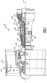
- FIG. 1 schematically illustrates a gas turbine engine 20.
- the gas turbine engine 20 is disclosed herein as a two-spool turbofan that generally incorporates a fan section 22, a compressor section 24, a combustor section 26 and a turbine section 28.
- the fan section 22 drives air along a bypass flow path B in a bypass duct defined within a housing 15 such as a fan case or nacelle, and also drives air along a core flow path C for compression and communication into the combustor section 26 then expansion through the turbine section 28.
- the exemplary engine 20 generally includes a low speed spool 30 and a high speed spool 32 mounted for rotation about an engine central longitudinal axis A relative to an engine static structure 36 via several bearing systems 38. It should be understood that various bearing systems 38 at various locations may alternatively or additionally be provided, and the location of bearing systems 38 may be varied as appropriate to the application.
- the low speed spool 30 generally includes an inner shaft 40 that interconnects, a first (or low) pressure compressor 44 and a first (or low) pressure turbine 46.
- the inner shaft 40 is connected to the fan 42 through a speed change mechanism, which in exemplary gas turbine engine 20 is illustrated as a geared architecture 48 to drive a fan 42 at a lower speed than the low speed spool 30.
- the high speed spool 32 includes an outer shaft 50 that interconnects a second (or high) pressure compressor 52 and a second (or high) pressure turbine 54.
- a combustor 56 is arranged in exemplary gas turbine 20 between the high pressure compressor 52 and the high pressure turbine 54.
- a mid-turbine frame 57 of the engine static structure 36 may be arranged generally between the high pressure turbine 54 and the low pressure turbine 46.
- the mid-turbine frame 57 further supports bearing systems 38 in the turbine section 28.
- the inner shaft 40 and the outer shaft 50 are concentric and rotate via bearing systems 38 about the engine central longitudinal axis A which is colline
- the core airflow is compressed by the low pressure compressor 44 then the high pressure compressor 52, mixed and burned with fuel in the combustor 56, then expanded over the high pressure turbine 54 and low pressure turbine 46.
- the mid-turbine frame 57 includes airfoils 59 which are in the core airflow path C.
- the turbines 46, 54 rotationally drive the respective low speed spool 30 and high speed spool 32 in response to the expansion.
- gear system 48 may be located aft of the low pressure compressor, or aft of the combustor section 26 or even aft of turbine section 28, and fan 42 may be positioned forward or aft of the location of gear system 48.
- the engine 20 in one example is a high-bypass geared aircraft engine.
- the engine 20 bypass ratio is greater than about six (6), with an example embodiment being greater than about ten (10)
- the geared architecture 48 is an epicyclic gear train, such as a planetary gear system or other gear system, with a gear reduction ratio of greater than about 2.3
- the low pressure turbine 46 has a pressure ratio that is greater than about five.
- the engine 20 bypass ratio is greater than about ten (10:1)
- the fan diameter is significantly larger than that of the low pressure compressor 44
- the low pressure turbine 46 has a pressure ratio that is greater than about five 5:1.
- Low pressure turbine 46 pressure ratio is pressure measured prior to inlet of low pressure turbine 46 as related to the pressure at the outlet of the low pressure turbine 46 prior to an exhaust nozzle.
- the geared architecture 48 may be an epicycle gear train, such as a planetary gear system or other gear system, with a gear reduction ratio of greater than about 2.3:1 and less than about 5:1. It should be understood, however, that the above parameters are only exemplary of one embodiment of a geared architecture engine and that the present invention is applicable to other gas turbine engines including direct drive turbofans.
- the fan section 22 of the engine 20 is designed for a particular flight condition -- typically cruise at about 0.8 Mach and about 35,000 feet (10,668 meters).
- the flight condition of 0.8 Mach and 35,000 ft (10,668 meters), with the engine at its best fuel consumption - also known as "bucket cruise Thrust Specific Fuel Consumption ('TSFC')" - is the industry standard parameter of lbm of fuel being burned divided by lbf of thrust the engine produces at that minimum point.
- "Low fan pressure ratio” is the pressure ratio across the fan blade alone, without a Fan Exit Guide Vane (“FEGV”) system.
- the low fan pressure ratio as disclosed herein according to one non-limiting embodiment is less than about 1.45.
- Low corrected fan tip speed is the actual fan tip speed in ft/sec divided by an industry standard temperature correction of [(Tram °R) / (518.7 °R)] 0.5 .
- the "Low corrected fan tip speed” as disclosed herein according to one non-limiting embodiment is less than about 1150 ft / second (350.5 meters/second).
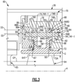
- Figure 2 illustrates an axial view of an example assembly 60 for a gas turbine engine.
- the assembly 60 can be incorporated into a portion of the engine 20 of Figure 1 , such as the turbine section 28.
- the assembly 60 is a blade outer air seal assembly for sealing portions of a gas turbine engine.
- the assembly 60 can alternatively or additionally be adapted for other portions of the engine 20, such as an upstream stage of the compressor section 24 or combustor panels defining portions of a combustion chamber located in the combustor section 26.
- teachings herein primarily refer to a two-spool gas turbine engine having a fan, other systems can benefit from the teachings herein, such as engines without a fan and other ground based systems.
- the assembly 60 is positioned radially outward of a rotor 62 having an array (or row) of airfoils or rotatable blades 64.
- the blades 64 are rotatable about the engine longitudinal axis A in a gas path GP, such as the core flow path C ( Figure 1 ).
- the blades 64 are positioned adjacent to one or more rows of vanes 65 (one shown in Figure 3 for illustrative purposes). Each vane 65 can be dimensioned to direct flow in the gas path GP towards the blades 64.
- the assembly 60 includes one or more gas turbine engine components 66.
- the components 66 are blade outer air seals (BOAS) or seal arc segments.
- the assembly 60 includes an array of seal arc segments 66 circumferentially arranged in an annulus around the engine longitudinal axis A and about the blades 64.
- the seal arc segments 66 are mounted to at least one support 68, which can be continuous or can be segmented as a plurality of supports (illustrated by dashed lines in Figure 2 ).
- the support 68 is mounted or attached to an engine case 70 through one or more connections 69.
- the engine case 70 is arranged about and extends along the engine axis A.
- the seal arc segments 66 are directly attached to the engine case 70.
- the engine case 70 can be mounted or attached to, or form a portion of, the engine static structure 36 (see also Figure 1 ).
- Each seal arc segment 66 can be formed of a material having a high temperature capability.
- Example high temperature materials include metallic alloys and ceramic-based materials, such as a monolithic ceramic or a ceramic matrix composite (CMC) material.
- An example of a high temperature metallic alloy is a nickel-based alloy.
- Monolithic ceramics include, but are not limited to, silicon carbide (SiC) or silicon nitride (Si 3 N 4 ).
- each seal arc segment 66 is formed of high-toughness material such as, but not limited to, single crystal metallic alloys.
- the seal arc segments 66 are positioned in close radial proximity to tips 64T of the blades 64 to reduce the amount of gas flow that escapes around the blades 64 and through a clearance gap G.
- the engine 20 can include an active or passive clearance control system to adjust the clearance gap G to a desired dimension during one or more operating conditions of the engine 20.
- the clearance gap G may also vary during operation of the engine 20, such as between a non-operating, cold state condition, and an operating condition such as a cruise and/or takeoff condition of the engine 20.
- FIG. 4 illustrates a perspective view of an example seal arc segment 66.
- Each seal arc segment 66 includes a sealing portion 72 and a first interface portion 74.
- the sealing portion 72 includes a generally arcuate sealing surface (or face) 72A extending between circumferential mate faces 72B, as illustrated by Figure 4 (see also Figure 2 ).
- the sealing surface 72A is dimensioned to bound portions of the gas path GP, such as the core flow path C of Figure 1 .
- the sealing portion 72 and first interface portion 74 can be made of any of the materials disclosed herein, including a ceramic-based material.
- the first interface portion 74 of the seal arc segment 66 includes a pair of rails 74R (indicated at 74R-1, 74R-2) extending radially outwardly from the sealing portion 72.
- An elongated slot or backside cavity 74S extends between the rails 74R. In examples, cooling airflow is communicated to the backside cavity 74S to cool adjacent portions of the seal arc segment 66.
- the first interface portion 74 can include a pair of interface flanges 74F (indicated at 74F-1, 74F-2) extending outwardly from the respective rails 74R-1, 74R-2 of the first interface portion 74.
- the interface flanges 74F and rails 74R can be made of any of the materials disclosed herein, including a ceramic-based material.
- the support 68 includes a mounting portion 76 and a second interface portion 78, which can be made of a metallic material.
- the mounting portion 76 is attachable to the engine static structure 36 directly or through the engine case 70.
- the assembly 60 includes a first (e.g., primary) retention feature 80 and a second (e.g., secondary) retention feature 82 that mount the seal arc segments 66 to the support 68 during engine operation.
- One of the first and second retention features 80, 82 is dimensioned to carry the seal arc segment 66 in response to release of another one of the first and second retention features 80, 82.
- the term "primary" retention feature refers to an arrangement that at least initially bears a load of the seal arc segment in an installed position
- secondary refers to an arrangement that does not bear any load or bears substantially less of the load of the seal arc segment when the load is borne by the primary retention feature in the installed position.
- first and second retention features 80, 82 are primarily referred to as primary and secondary retention features, respectively, in the example of Figures 3-5 , in other examples the first retention feature 80 serves as the secondary retention feature, and the second retention feature 82 serves as the primary retention feature.
- the retention features 80, 82 are dimensioned to establish and maintain a set of predetermined distances between the sealing surface 72A of the seal arc segments 66 and the blade tips 64T across the clearance gap GP.
- the first and second retention features 80, 82 can be dimensioned with respect to expected manufacturing and design tolerances and expected thermal distortions of the components of the assembly 60 during engine operation.
- a position of the first interface portion 74 changes relative to the second interface portion 78 due to a release of the first retention feature 80 when the seal arc segment 66 is situated in the first installed position.
- Such changes may occur due to shearing of a retention pin 84, or delamination or sheering of the CMC material of the seal arc segment 66 due to stress concentrations when the seal arc segment 66 is situated in the first installed position, for example.
- the first and second retention features 80, 82 cooperate to maintain a clearance between the seal arc segments 66 and the adjacent blades 64.
- first and second retention features 80, 82 can be utilized.
- the first and second retention features 80, 82 can be the same or can differ.
- the first retention feature 80 can be arranged to releasably secure the first interface portion 74 to the support 68 in a first installed position of the seal arc segment 66.
- Example retention features include fasteners such as clips, pins, bolts and rivets, as well as other components that mechanically join objects together such as a length of wire.
- the first retention feature 80 includes one or more retention pins (or members) 84 dimensioned to engage the support 68 and the first interface portion 74 of a respective one of the seal arc segments 66 such that each of the seal arc segments 66 is carried by one or more of the retention pins 84 in the first installed position of the seal arc segment 66.
- the seal arc segment 66, support 68 and retention pins 84 are separate and distinct components.
- Each retention pin 84 includes an elongated main body 84A extending between opposed first and second end portions 84B, 84C.
- the first interface portion 74 includes one or more interface bores 74B extending through a respective rail 74R.
- Each interface bore 74B of the rail 74R-1 is partially or completely radially aligned with a respective interface bore 74B of the rail 74R-2.
- Each interface bore 74B has a diameter that is greater than a diameter of a respective one of the retention pins 84.
- the second interface portion 78 includes one or more support bores 78B (one shown in Figure 3 for illustrative purposes).
- the interface and support bores 74B, 78B are dimensioned to at least partially receive a respective retention pin 84 to establish the first installed position of the seal arc segment 66.
- the assembly 60 includes a seal plate 86 attached or releasably secured to the support 68.
- Various techniques can be utilized to secure the seal plate 86 to the support 68, such as one or more fasteners.
- the seal plate 86 has a generally arcuate geometry and extends about the engine longitudinal axis A (shown in dashed lines in Figure 2 for illustrative purposes).
- the seal plate 86 includes a plate flange 86F extending outwardly from a plate body 86A.
- the seal plate 86 includes one or more plate bores 86B (one shown in Figure 3 for illustrative purposes) dimensioned to at least partially receive the retention pin 84 to establish the first installed position of the seal arc segment 66.
- a seal member 87 is captured between the seal arc segment 66 and seal plate 86.
- the seal member 87 is a W-seal arranged to oppose flow along an axial gap between the seal arc segment 66 and seal plate 86.
- Each of the interface flanges 74F can include a sacrificial member 88 disposed on surfaces of the flange 74F.
- the sacrificial member 88 can be made of a material that differs from a material of the respective flange 74F.
- the sacrificial member 88 can be machined or otherwise formed to have a complementary geometry with the respective flange 78F/86F while preserving a construction of the underlying laminate structure.
- the sacrificial member 88 can be a coating or constructed from one or more sacrificial plies or layers, and is dimensioned to eliminate or otherwise reduce direct contact between surfaces of the interface flange 74F and the respective flange 78F/86F.
- An example coating includes a silicon metal that is adapted to substantially match a rate of thermal expansion of the seal arc segment 66 to reduce a likelihood of spalling of the laminate structure of the CMC layup.
- the support 68 can include at least one face seal 90 dimensioned to engage the first interface portion 74 directly or along the adjacent sacrificial member 88.
- the face seal 90 is dimensioned to oppose flow along an axial gap between the first interface portion 74 and second interface portion 78 of the support 68.
- each interface bore 74B is partially or completely radially aligned with an adjacent support bore 78B and/or plate bore 86B.
- Each retention pin 84 is slidably received in, and extends at least partially through, the interface bore 74B of each rail 74R-1, 74R-2 and is received in a respective support bore 78B and plate bore 86B to secure the first interface portion 74 to the support 68 in the first installed position.
- the support 68 and seal plate 86 are dimensioned to trap the retention pin(s) 84 in the first installed position.
- the first end portion 84B of the retention pin 84 is at least partially inserted into the respective support bore 78B, and the second end portion 84C of the retention pin 84 is at least partially inserted into the respective plate bore 86B.
- Various techniques can be utilized to secure the retention pin 84 to the support 68 and/or seal plate 86, such as press fitting or threadedly attaching the retention pin 84 in the support bore 78B and/or plate bore 86B.
- Each interface bore 74B is dimensioned such the rails 74R of the seal arc segment 66 are carried by an outer periphery 84D of the retention pin(s) 84 in the first installed position.
- the interface bores 74B are dimensioned such that the rails 74R of the first interface portion 74 sit on a radially outer surface 84RO of the retention pin 84 in the first installed position, as illustrated by Figure 3 .
- the interface bores 74B is dimensioned such that the rails 74R are spaced apart from a radially inner surface 84RI of the retention pin 84 in the first installed position to accommodate differences in thermal expansion of rails 74R, retention pin 84, support 68 and/or support plate 86 during engine operation.
- a diameter of the retention pin 84 is substantially equal to a diameter of the interface bores 74B.
- the second retention feature 82 is dimensioned to secure the first interface portion 74 of the seal arc segment 66 to the second interface portion 78 of the support 68 in a second installed position of the seal arc segment 66, as illustrated by seal arc segment 66' of Figure 5 .
- the first installed position of the seal arc segment 66 differs from the second installed position of seal arc segment 66'.
- the second retention feature 82 is dimensioned to bound radial movement of the seal arc segment 66 towards the engine longitudinal axis A and secure the seal arc segment 66 in the second installed position in response to a release of the first retention feature 80 when the seal arc segment 66 is in the first installed position.
- the second retention feature 82 is dimensioned such that a clearance gap G' is maintained between a sealing surface 72A' of the seal arc segment 66' and a blade tip 64T' of the adjacent blade 64'.
- the first installed position of the seal arc segment 66 is radially outward of the second installed position of the seal arc segment 66' such that a dimension of the clearance gap G is greater than a dimension of the clearance gap G'.
- the support 68 includes a support flange 78F extending outwardly from the second interface portion 78.
- the interface flanges 74F are at least partially axially aligned with the respective the support flange 78F and plate flange 86F relative to the engine longitudinal axis A.
- the interface flange(s) 74F together with the support flange 78F and/or plate flange 86F cooperate to establish the second retention feature 82.
- the support flange 78F and/or plate flange 86F are dimensioned to carry a load of the seal arc segment 66 in the second installed position, but not in the first installed position, in response to a release of the first retention feature 80 when the seal arc segment 66 is situated in the first installed position.
- the second retention feature 82 can be dimensioned to carry at least a portion or substantially all of the load of the seal arc segment 66.
- the interface flange(s) 74F' are dimensioned to sit on the support flange 78F' and plate flange 86F' in the second installed position to limit radially inward movement of the seal arc segment 66' towards the engine longitudinal axis A.
- Each sacrificial member 88' is dimensioned to engage the support flange 78F' and/or plate flange 86F' in the second installed position.
- the sacrificial member 88' is disposed on the support flange 78F' and/or plate flange 86F' or is omitted such that the interface flanges 74F' directly contacts the support flange 78F'.
- the assembly 60 can be assembled as follows.
- the first interface portion 74 of the seal arc segment 66 is positioned relative to the second interface portion 78 of the support 68 such that engagement of the first and second interface portions 74, 78 establishes the second installed position of the seal arc segment 66 in which the seal arc segment 66 is carried by the support 68.
- At least one retention pin 84 is moved in a direction D2 ( Figures 3-4 ) and is inserted in the interface bore(s) 74B and in the support bore 78B such that engagement of the retention pin 84 with surfaces of the interface bore(s) 74B and surfaces of the support bore 78B establishes the first installed position in which the seal arc segment 66 is carried by the retention pin 84.
- the seal plate 86 is secured to the support 68 to trap the retention pins 84 and to establish the first installed position.
- the retention pin 84 is received in a respective plate bore 86F.
- each seal arc segment 66 is carried by the first retention feature 80 in the first installed position to seal portions of the gas path GP.
- the seal arc segment 66 moves in the radially inward direction D1 ( Figure 5 ) towards the engine longitudinal axis A from the first installed position to the second installed position.
- the second retention feature 82 captures the seal arc segment in the second installed position to reduce a likelihood of contact between the seal arc segment 66 and adjacent blades 64 during operation.
- the second retention feature 82 can be adapted to redistribute pressure loads carried by the first retention feature 80 over additional surface area due to engagement of the first and second retention features 80, 82 in the second installed position of the seal arc segment 66.
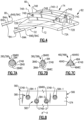
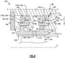
- Figure 6 illustrates an assembly 160 for a gas turbine engine according to another example.
- like reference numerals designate like elements where appropriate and reference numerals with the addition of one-hundred or multiples thereof designate modified elements that are understood to incorporate the same features and benefits of the corresponding original elements.
- the assembly 160 includes at least one seal arc segment 166, at least one support 168 and a seal plate 186.
- the seal arc segment 166 and support 168 cooperate to establish a first retention feature 180 and a second retention feature 182.
- the seal arc segment 166 includes a first interface portion 174 extending outwardly from a sealing portion 172.
- the first interface portion 174 includes a pair of rails 174R (indicated at 174R-1, 174R-2).
- a pair of retention hooks 174H (indicated at 174H-1, 174H-2) extend transversely from the respective rails 174R-1, 174R-2.
- the support 168 includes a second interface portion 178 having a pair of retention hooks 178H (indicated at 178H-1, 178H-2) dimensioned to mate with the retention hooks 174H-1, 174H-2.
- a sacrificial member 188 can be disposed on surfaces of each retention hook 174H and can be dimensioned to engage surfaces of the adjacent retention rail 178H.
- the retention hooks 174H, 178H cooperate to establish the first retention feature 180.
- the retention hooks 174H of the seal arc segment 166 are dimensioned to sit on and be carried by the retention hooks 178H of the support 168 in a first (e.g., primary) installed position of the seal arc segment 166.
- the second retention feature 182 includes one or more retentions pin 184 that engages the second interface portion 178 to secure the seal arc segment 166 to the support 168.
- the second retention feature 182 a pair of retention pins 184 (indicated at 184-1, 184-2) that mount the seal arc segment 166 to the support 168.
- Each retention pin 184 is slidably received in, and extends at least partially through, an interface bore 174B of the respective rail 174R and is inserted in a respective support bore 178B to secure the first interface portion 174 to the support 168 in a second (e.g., secondary) installed position of the seal arc segment 166.
- Each interface bore 174B is dimensioned such that the rails 174R sit on and are carried by the retention pins 184 in the second installed position, but not in the first installed position, in response to movement of the seal arc segment 166 in a radially inward (or first) direction D1 towards the engine longitudinal axis A from the first installed position to the second installed position.
- the second installed position of the seal arc segment 166 is illustrated by dashed line 166' in Figure 6 .
- the retention pins can have various profiles, such as a circular cross section as illustrated by retention pin 284 of Figure 7A , a non-circular elliptical cross section as illustrated by retention pin 384 of Figure 7B , or a generally triangular cross section as illustrated by retention pin 484 of Figure 7C .
- Other example retention pin profiles include a rectangular or complex cross section.
- the interface bores disclosed herein can be dimensioned to accept retention pins having different diameters or widths to set a predefined radial position of the respective seal arc segment relative to the engine longitudinal axis A.
- a geometry of the interface bores differ from a geometry of the retention pins.
- the retention pin 484 can be utilized in one of the interface bores 274B/374B.
- the retention pin 284 can be utilized in one of the interface bores 374B/474B.
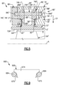
- Figure 8 illustrates an assembly 560 according to another example.
- a first retention feature 580 of a gas turbine engine component or seal arc segment 566 is established by a first set of retention pins 584-1
- a second retention feature 582 is established by a second set of retention pins 584-2.
- the first set of retention pins 584-1 are received in a first set of interface bores 574B-1 of first interface portion 574 to establish a first installed position of the seal arc segment 566.
- the second set of retention pins 584-2 are received in a second set of interface bores 574B-2 of the of first interface portion 574 to establish a second installed position of the seal arc segment 566.
- the first set of retention pins 584-1 are dimensioned to carry a load of the seal arc segment 566 in the first installed position.
- the second set of retention pins 584-2 are dimensioned to carry a load of the seal arc segment 566 in the second installed position, but not in the first installed position.
- the first set of interface bores 574B-1 are radially offset from the second set of interface bores 574-2.
- the second set of interface bores 574-2 are dimensioned such that a radially outer surface 584RO of each retention pin 584-2 is spaced apart from the respective interface bore 574B-2 in the first installed position, but not the second installed position of the seal arc segment 566.
- Figure 9 illustrates an assembly 660 according to yet another example.
- a set of retention pins 684 are dimensioned to abut circumferentially opposed shoulders 675 of seal arc segment 666.
- the shoulders 675 can have a generally dovetail geometry.
- the shoulders 675 can be utilized to establish the first or second installed position of the seal arc segment 666.
Landscapes
- Engineering & Computer Science (AREA)
- Mechanical Engineering (AREA)
- General Engineering & Computer Science (AREA)
- Chemical & Material Sciences (AREA)
- Combustion & Propulsion (AREA)
- Gasket Seals (AREA)
- Turbine Rotor Nozzle Sealing (AREA)
Applications Claiming Priority (2)
| Application Number | Priority Date | Filing Date | Title |
|---|---|---|---|
| US16/695,616 US11174795B2 (en) | 2019-11-26 | 2019-11-26 | Seal assembly with secondary retention feature |
| EP20208790.4A EP3828391B1 (de) | 2019-11-26 | 2020-11-20 | Dichtungsanordnung für ein gasturbinentriebwerk |
Related Parent Applications (2)
| Application Number | Title | Priority Date | Filing Date |
|---|---|---|---|
| EP20208790.4A Division EP3828391B1 (de) | 2019-11-26 | 2020-11-20 | Dichtungsanordnung für ein gasturbinentriebwerk |
| EP20208790.4A Division-Into EP3828391B1 (de) | 2019-11-26 | 2020-11-20 | Dichtungsanordnung für ein gasturbinentriebwerk |
Publications (3)
| Publication Number | Publication Date |
|---|---|
| EP4239166A2 true EP4239166A2 (de) | 2023-09-06 |
| EP4239166A3 EP4239166A3 (de) | 2023-12-13 |
| EP4239166B1 EP4239166B1 (de) | 2026-03-11 |
Family
ID=73543042
Family Applications (2)
| Application Number | Title | Priority Date | Filing Date |
|---|---|---|---|
| EP20208790.4A Active EP3828391B1 (de) | 2019-11-26 | 2020-11-20 | Dichtungsanordnung für ein gasturbinentriebwerk |
| EP23187614.5A Active EP4239166B1 (de) | 2019-11-26 | 2020-11-20 | Dichtungsanordnung für einen gasturbinentriebwerk und entsprechendes dichtungsverfahren |
Family Applications Before (1)
| Application Number | Title | Priority Date | Filing Date |
|---|---|---|---|
| EP20208790.4A Active EP3828391B1 (de) | 2019-11-26 | 2020-11-20 | Dichtungsanordnung für ein gasturbinentriebwerk |
Country Status (2)
| Country | Link |
|---|---|
| US (2) | US11174795B2 (de) |
| EP (2) | EP3828391B1 (de) |
Families Citing this family (31)
| Publication number | Priority date | Publication date | Assignee | Title |
|---|---|---|---|---|
| IT201900001173A1 (it) * | 2019-01-25 | 2020-07-25 | Nuovo Pignone Tecnologie Srl | Turbina con un anello avvolgente attorno a pale rotoriche e metodo per limitare la perdita di fluido di lavoro in una turbina |
| US11143050B2 (en) * | 2020-02-13 | 2021-10-12 | Raytheon Technologies Corporation | Seal assembly with reduced pressure load arrangement |
| FR3120900B1 (fr) * | 2021-03-18 | 2023-02-10 | Safran Aircraft Engines | Dispositif de centrage et de guidage d’un arbre de turbomachine d’aeronef |
| US11959389B2 (en) * | 2021-06-11 | 2024-04-16 | Pratt & Whitney Canada Corp. | Turbine shroud segments with angular locating feature |
| FR3131597B1 (fr) * | 2022-01-06 | 2024-02-16 | Safran Ceram | Turbine pour turbomachine |
| US12031443B2 (en) | 2022-11-29 | 2024-07-09 | Rolls-Royce Corporation | Ceramic matrix composite blade track segment with attachment flange cooling chambers |
| US11773751B1 (en) | 2022-11-29 | 2023-10-03 | Rolls-Royce Corporation | Ceramic matrix composite blade track segment with pin-locating threaded insert |
| US11713694B1 (en) | 2022-11-30 | 2023-08-01 | Rolls-Royce Corporation | Ceramic matrix composite blade track segment with two-piece carrier |
| US11840936B1 (en) | 2022-11-30 | 2023-12-12 | Rolls-Royce Corporation | Ceramic matrix composite blade track segment with pin-locating shim kit |
| US11732604B1 (en) | 2022-12-01 | 2023-08-22 | Rolls-Royce Corporation | Ceramic matrix composite blade track segment with integrated cooling passages |
| US11885225B1 (en) | 2023-01-25 | 2024-01-30 | Rolls-Royce Corporation | Turbine blade track with ceramic matrix composite segments having attachment flange draft angles |
| US12228033B1 (en) * | 2023-10-13 | 2025-02-18 | Rtx Corporation | Blade outer air seal with machinable coating at sealing surfaces |
| US12286885B1 (en) | 2023-12-04 | 2025-04-29 | Rolls-Royce Corporation | Turbine assembly with confronting vane and turbine shroud segment |
| US12158072B1 (en) | 2023-12-04 | 2024-12-03 | Rolls-Royce Corporation | Turbine shroud segments with damping strip seals |
| US12188365B1 (en) | 2023-12-04 | 2025-01-07 | Rolls-Royce Corporation | Method and apparatus for ceramic matrix composite turbine shroud assembly |
| US12421862B2 (en) | 2023-12-04 | 2025-09-23 | Rolls-Royce Corporation | Turbine shroud assembly with angled cooling holes |
| US12152499B1 (en) | 2023-12-04 | 2024-11-26 | Rolls-Royce Corporation | Turbine shroud segments with strip seal assemblies having dampened ends |
| US12286906B1 (en) | 2023-12-04 | 2025-04-29 | Rolls-Royce Corporation | Locating plate for use with turbine shroud assemblies |
| US12241376B1 (en) | 2023-12-04 | 2025-03-04 | Rolls-Royce Corporation | Locating plate for use with turbine shroud assemblies |
| US12258867B1 (en) * | 2024-01-31 | 2025-03-25 | Rtx Corporation | Attachment for blade outer air seal |
| US12421870B1 (en) | 2024-04-30 | 2025-09-23 | Rolls-Royce Corporation | Pin mounted ceramic matrix composite heat shields with impingement cooling |
| FR3162459A1 (fr) * | 2024-05-27 | 2025-11-28 | Safran Ceramics | Turbine pour turbomachine |
| US12305525B1 (en) | 2024-05-30 | 2025-05-20 | Rolls-Royce Corporation | Turbine shroud assemblies with rod seal and strip seals |
| US12416241B1 (en) | 2024-05-30 | 2025-09-16 | Rolls-Royce Corporation | Turbine shroud assemblies with strip seals |
| US12215593B1 (en) | 2024-05-30 | 2025-02-04 | Rolls-Royce Corporation | Turbine shroud assembly with inter-segment damping |
| US12258880B1 (en) | 2024-05-30 | 2025-03-25 | Rolls-Royce Corporation | Turbine shroud assemblies with inter-segment strip seal |
| US12410725B1 (en) | 2024-05-31 | 2025-09-09 | Rolls-Royce Corporation | Turbine shroud assemblies with air activated pistons for biasing buffer cavity seals |
| US12577881B2 (en) | 2024-05-31 | 2026-03-17 | Rolls-Royce Corporation | Turbine shroud assemblies with anti-migration seals |
| US12352176B1 (en) | 2024-05-31 | 2025-07-08 | Rolls-Royce Corporation | Turbine shroud assemblies with channels for buffer cavity seal thermal management |
| US12228044B1 (en) | 2024-06-26 | 2025-02-18 | Rolls-Royce Corporation | Turbine shroud system with ceramic matrix composite segments and dual inter-segment seals |
| US12359585B1 (en) * | 2024-11-19 | 2025-07-15 | Rtx Corporation | Dual pin support for blade outer air seal and method |
Family Cites Families (25)
| Publication number | Priority date | Publication date | Assignee | Title |
|---|---|---|---|---|
| US4650394A (en) * | 1984-11-13 | 1987-03-17 | United Technologies Corporation | Coolable seal assembly for a gas turbine engine |
| US7874795B2 (en) | 2006-09-11 | 2011-01-25 | General Electric Company | Turbine nozzle assemblies |
| US8684680B2 (en) * | 2009-08-27 | 2014-04-01 | Pratt & Whitney Canada Corp. | Sealing and cooling at the joint between shroud segments |
| US8439636B1 (en) * | 2009-10-20 | 2013-05-14 | Florida Turbine Technologies, Inc. | Turbine blade outer air seal |
| US8753073B2 (en) | 2010-06-23 | 2014-06-17 | General Electric Company | Turbine shroud sealing apparatus |
| US8579580B2 (en) | 2010-12-30 | 2013-11-12 | General Electric Company | Mounting apparatus for low-ductility turbine shroud |
| US8985944B2 (en) | 2011-03-30 | 2015-03-24 | General Electric Company | Continuous ring composite turbine shroud |
| US8790067B2 (en) * | 2011-04-27 | 2014-07-29 | United Technologies Corporation | Blade clearance control using high-CTE and low-CTE ring members |
| US9945256B2 (en) * | 2014-06-27 | 2018-04-17 | Rolls-Royce Corporation | Segmented turbine shroud with seals |
| US9874104B2 (en) | 2015-02-27 | 2018-01-23 | General Electric Company | Method and system for a ceramic matrix composite shroud hanger assembly |
| US9863265B2 (en) | 2015-04-15 | 2018-01-09 | General Electric Company | Shroud assembly and shroud for gas turbine engine |
| FR3036435B1 (fr) * | 2015-05-22 | 2020-01-24 | Safran Ceramics | Ensemble d'anneau de turbine |
| US10370998B2 (en) | 2015-05-26 | 2019-08-06 | Rolls-Royce Corporation | Flexibly mounted ceramic matrix composite seal segments |
| US10221713B2 (en) * | 2015-05-26 | 2019-03-05 | Rolls-Royce Corporation | Shroud cartridge having a ceramic matrix composite seal segment |
| US10385718B2 (en) | 2015-06-29 | 2019-08-20 | Rolls-Royce North American Technologies, Inc. | Turbine shroud segment with side perimeter seal |
| US10030541B2 (en) * | 2015-07-01 | 2018-07-24 | Rolls-Royce North American Technologies Inc. | Turbine shroud with clamped flange attachment |
| US10301960B2 (en) | 2015-07-13 | 2019-05-28 | General Electric Company | Shroud assembly for gas turbine engine |
| US10563534B2 (en) | 2015-12-02 | 2020-02-18 | United Technologies Corporation | Blade outer air seal with seal arc segment having secondary radial supports |
| FR3045715B1 (fr) * | 2015-12-18 | 2018-01-26 | Safran Aircraft Engines | Ensemble d'anneau de turbine avec maintien a froid et a chaud |
| FR3045716B1 (fr) * | 2015-12-18 | 2018-01-26 | Safran Aircraft Engines | Ensemble d'anneau de turbine avec maintien elastique a froid |
| US10677084B2 (en) * | 2017-06-16 | 2020-06-09 | Honeywell International Inc. | Turbine tip shroud assembly with plural shroud segments having inter-segment seal arrangement |
| US10619514B2 (en) * | 2017-10-18 | 2020-04-14 | Rolls-Royce Corporation | Ceramic matrix composite assembly with compliant pin attachment features |
| EP3763918B1 (de) * | 2018-03-07 | 2025-10-22 | Kawasaki Jukogyo Kabushiki Kaisha | Deckbandmontagestruktur für gasturbine |
| JP7018131B2 (ja) * | 2018-05-11 | 2022-02-09 | 川崎重工業株式会社 | ガスタービンのシュラウド組立体 |
| US11220925B2 (en) * | 2019-10-10 | 2022-01-11 | Rolls-Royce North American Technologies Inc. | Turbine shroud with friction mounted ceramic matrix composite blade track |
-
2019
- 2019-11-26 US US16/695,616 patent/US11174795B2/en active Active
-
2020
- 2020-11-20 EP EP20208790.4A patent/EP3828391B1/de active Active
- 2020-11-20 EP EP23187614.5A patent/EP4239166B1/de active Active
-
2021
- 2021-10-29 US US17/513,995 patent/US11492978B2/en active Active
Also Published As
| Publication number | Publication date |
|---|---|
| US20220049659A1 (en) | 2022-02-17 |
| US11492978B2 (en) | 2022-11-08 |
| EP4239166A3 (de) | 2023-12-13 |
| US20210156311A1 (en) | 2021-05-27 |
| US11174795B2 (en) | 2021-11-16 |
| EP3828391B1 (de) | 2023-09-13 |
| EP3828391A3 (de) | 2021-09-29 |
| EP4239166B1 (de) | 2026-03-11 |
| EP3828391A2 (de) | 2021-06-02 |
Similar Documents
| Publication | Publication Date | Title |
|---|---|---|
| EP4239166B1 (de) | Dichtungsanordnung für einen gasturbinentriebwerk und entsprechendes dichtungsverfahren | |
| US11624291B2 (en) | Seal assembly with reduced pressure load arrangement | |
| US11174747B2 (en) | Seal assembly with distributed cooling arrangement | |
| EP3819475B1 (de) | Äussere laufschaufelluftdichtungsanordnung und verfahren zur abdichtung | |
| EP3792453B1 (de) | Cmc-boas-anordnung | |
| EP3667029B1 (de) | Dichtungsanordnung eines gasturbinenmotors mit duktiler verschleissauskleidung | |
| US11021986B2 (en) | Seal assembly for gas turbine engine | |
| EP3219934B1 (de) | Dichtungssatz für gasturbinentriebwerk | |
| EP3141703B1 (de) | Dichtungsanordnung für turbinenmotorkomponente | |
| EP3620616B1 (de) | Turbinensektion mit boas-kühlluftstromführung | |
| EP3620615B1 (de) | Cmc-schaufelaussenluftdichtungsanordnung mit axialhalteklemme | |
| US10801351B2 (en) | Seal assembly for gas turbine engine | |
| EP3825518A1 (de) | Leitschaufelrückhalteeinrichtung | |
| US10689997B2 (en) | Seal assembly for gas turbine engine | |
| EP3401515B1 (de) | Turbinenschaufel mit inneren umlaufenden verdrehsicherungsmerkmalen | |
| EP3620611B1 (de) | Einheitlicher boas-träger und schaufelplattform | |
| US11814966B2 (en) | Retention ring with removal features for gas turbine engine |
Legal Events
| Date | Code | Title | Description |
|---|---|---|---|
| PUAI | Public reference made under article 153(3) epc to a published international application that has entered the european phase |
Free format text: ORIGINAL CODE: 0009012 |
|
| STAA | Information on the status of an ep patent application or granted ep patent |
Free format text: STATUS: THE APPLICATION HAS BEEN PUBLISHED |
|
| AC | Divisional application: reference to earlier application |
Ref document number: 3828391 Country of ref document: EP Kind code of ref document: P |
|
| AK | Designated contracting states |
Kind code of ref document: A2 Designated state(s): AL AT BE BG CH CY CZ DE DK EE ES FI FR GB GR HR HU IE IS IT LI LT LU LV MC MK MT NL NO PL PT RO RS SE SI SK SM TR |
|
| RAP3 | Party data changed (applicant data changed or rights of an application transferred) |
Owner name: RTX CORPORATION |
|
| REG | Reference to a national code |
Ref country code: DE Ref legal event code: R079 Ipc: F01D0011000000 Ref country code: DE Ref legal event code: R079 Ref document number: 602020068670 Country of ref document: DE Free format text: PREVIOUS MAIN CLASS: F01D0025240000 Ipc: F01D0011000000 |
|
| PUAL | Search report despatched |
Free format text: ORIGINAL CODE: 0009013 |
|
| AK | Designated contracting states |
Kind code of ref document: A3 Designated state(s): AL AT BE BG CH CY CZ DE DK EE ES FI FR GB GR HR HU IE IS IT LI LT LU LV MC MK MT NL NO PL PT RO RS SE SI SK SM TR |
|
| RIC1 | Information provided on ipc code assigned before grant |
Ipc: F01D 11/12 20060101ALN20231103BHEP Ipc: F01D 25/24 20060101ALI20231103BHEP Ipc: F01D 21/08 20060101ALI20231103BHEP Ipc: F01D 11/00 20060101AFI20231103BHEP |
|
| STAA | Information on the status of an ep patent application or granted ep patent |
Free format text: STATUS: REQUEST FOR EXAMINATION WAS MADE |
|
| 17P | Request for examination filed |
Effective date: 20240612 |
|
| RBV | Designated contracting states (corrected) |
Designated state(s): AL AT BE BG CH CY CZ DE DK EE ES FI FR GB GR HR HU IE IS IT LI LT LU LV MC MK MT NL NO PL PT RO RS SE SI SK SM TR |
|
| GRAP | Despatch of communication of intention to grant a patent |
Free format text: ORIGINAL CODE: EPIDOSNIGR1 |
|
| STAA | Information on the status of an ep patent application or granted ep patent |
Free format text: STATUS: GRANT OF PATENT IS INTENDED |
|
| RIC1 | Information provided on ipc code assigned before grant |
Ipc: F01D 11/00 20060101AFI20250924BHEP Ipc: F01D 21/08 20060101ALI20250924BHEP Ipc: F01D 25/24 20060101ALI20250924BHEP Ipc: F01D 11/12 20060101ALN20250924BHEP |
|
| INTG | Intention to grant announced |
Effective date: 20251008 |
|
| GRAS | Grant fee paid |
Free format text: ORIGINAL CODE: EPIDOSNIGR3 |
|
| GRAA | (expected) grant |
Free format text: ORIGINAL CODE: 0009210 |
|
| STAA | Information on the status of an ep patent application or granted ep patent |
Free format text: STATUS: THE PATENT HAS BEEN GRANTED |
|
| AC | Divisional application: reference to earlier application |
Ref document number: 3828391 Country of ref document: EP Kind code of ref document: P |
|
| AK | Designated contracting states |
Kind code of ref document: B1 Designated state(s): AL AT BE BG CH CY CZ DE DK EE ES FI FR GB GR HR HU IE IS IT LI LT LU LV MC MK MT NL NO PL PT RO RS SE SI SK SM TR |
|
| REG | Reference to a national code |
Ref country code: CH Ref legal event code: F10 Free format text: ST27 STATUS EVENT CODE: U-0-0-F10-F00 (AS PROVIDED BY THE NATIONAL OFFICE) Effective date: 20260311 Ref country code: GB Ref legal event code: FG4D |