EP4239164A2 - Method for constructing a fixed-vane ring for a nozzle of a turbocharger turbine - Google Patents
Method for constructing a fixed-vane ring for a nozzle of a turbocharger turbine Download PDFInfo
- Publication number
- EP4239164A2 EP4239164A2 EP22203979.4A EP22203979A EP4239164A2 EP 4239164 A2 EP4239164 A2 EP 4239164A2 EP 22203979 A EP22203979 A EP 22203979A EP 4239164 A2 EP4239164 A2 EP 4239164A2
- Authority
- EP
- European Patent Office
- Prior art keywords
- vane
- nozzle ring
- face
- nozzle
- vanes
- Prior art date
- Legal status (The legal status is an assumption and is not a legal conclusion. Google has not performed a legal analysis and makes no representation as to the accuracy of the status listed.)
- Granted
Links
Images





Classifications
-
- B—PERFORMING OPERATIONS; TRANSPORTING
- B23—MACHINE TOOLS; METAL-WORKING NOT OTHERWISE PROVIDED FOR
- B23P—METAL-WORKING NOT OTHERWISE PROVIDED FOR; COMBINED OPERATIONS; UNIVERSAL MACHINE TOOLS
- B23P15/00—Making specific metal objects by operations not covered by a single other subclass or a group in this subclass
- B23P15/006—Making specific metal objects by operations not covered by a single other subclass or a group in this subclass turbine wheels
-
- F—MECHANICAL ENGINEERING; LIGHTING; HEATING; WEAPONS; BLASTING
- F01—MACHINES OR ENGINES IN GENERAL; ENGINE PLANTS IN GENERAL; STEAM ENGINES
- F01D—NON-POSITIVE DISPLACEMENT MACHINES OR ENGINES, e.g. STEAM TURBINES
- F01D9/00—Stators
- F01D9/02—Nozzles; Nozzle boxes; Stator blades; Guide conduits, e.g. individual nozzles
- F01D9/04—Nozzles; Nozzle boxes; Stator blades; Guide conduits, e.g. individual nozzles forming ring or sector
- F01D9/041—Nozzles; Nozzle boxes; Stator blades; Guide conduits, e.g. individual nozzles forming ring or sector using blades
-
- B—PERFORMING OPERATIONS; TRANSPORTING
- B23—MACHINE TOOLS; METAL-WORKING NOT OTHERWISE PROVIDED FOR
- B23P—METAL-WORKING NOT OTHERWISE PROVIDED FOR; COMBINED OPERATIONS; UNIVERSAL MACHINE TOOLS
- B23P15/00—Making specific metal objects by operations not covered by a single other subclass or a group in this subclass
- B23P15/04—Making specific metal objects by operations not covered by a single other subclass or a group in this subclass turbine or like blades from several pieces
-
- F—MECHANICAL ENGINEERING; LIGHTING; HEATING; WEAPONS; BLASTING
- F01—MACHINES OR ENGINES IN GENERAL; ENGINE PLANTS IN GENERAL; STEAM ENGINES
- F01D—NON-POSITIVE DISPLACEMENT MACHINES OR ENGINES, e.g. STEAM TURBINES
- F01D9/00—Stators
- F01D9/02—Nozzles; Nozzle boxes; Stator blades; Guide conduits, e.g. individual nozzles
- F01D9/04—Nozzles; Nozzle boxes; Stator blades; Guide conduits, e.g. individual nozzles forming ring or sector
- F01D9/042—Nozzles; Nozzle boxes; Stator blades; Guide conduits, e.g. individual nozzles forming ring or sector fixing blades to stators
- F01D9/044—Nozzles; Nozzle boxes; Stator blades; Guide conduits, e.g. individual nozzles forming ring or sector fixing blades to stators permanently, e.g. by welding, brazing, casting or the like
-
- F—MECHANICAL ENGINEERING; LIGHTING; HEATING; WEAPONS; BLASTING
- F02—COMBUSTION ENGINES; HOT-GAS OR COMBUSTION-PRODUCT ENGINE PLANTS
- F02B—INTERNAL-COMBUSTION PISTON ENGINES; COMBUSTION ENGINES IN GENERAL
- F02B39/00—Component parts, details, or accessories relating to, driven charging or scavenging pumps, not provided for in groups F02B33/00 - F02B37/00
-
- F—MECHANICAL ENGINEERING; LIGHTING; HEATING; WEAPONS; BLASTING
- F05—INDEXING SCHEMES RELATING TO ENGINES OR PUMPS IN VARIOUS SUBCLASSES OF CLASSES F01-F04
- F05D—INDEXING SCHEME FOR ASPECTS RELATING TO NON-POSITIVE-DISPLACEMENT MACHINES OR ENGINES, GAS-TURBINES OR JET-PROPULSION PLANTS
- F05D2220/00—Application
- F05D2220/40—Application in turbochargers
-
- F—MECHANICAL ENGINEERING; LIGHTING; HEATING; WEAPONS; BLASTING
- F05—INDEXING SCHEMES RELATING TO ENGINES OR PUMPS IN VARIOUS SUBCLASSES OF CLASSES F01-F04
- F05D—INDEXING SCHEME FOR ASPECTS RELATING TO NON-POSITIVE-DISPLACEMENT MACHINES OR ENGINES, GAS-TURBINES OR JET-PROPULSION PLANTS
- F05D2230/00—Manufacture
- F05D2230/20—Manufacture essentially without removing material
- F05D2230/23—Manufacture essentially without removing material by permanently joining parts together
- F05D2230/232—Manufacture essentially without removing material by permanently joining parts together by welding
-
- F—MECHANICAL ENGINEERING; LIGHTING; HEATING; WEAPONS; BLASTING
- F05—INDEXING SCHEMES RELATING TO ENGINES OR PUMPS IN VARIOUS SUBCLASSES OF CLASSES F01-F04
- F05D—INDEXING SCHEME FOR ASPECTS RELATING TO NON-POSITIVE-DISPLACEMENT MACHINES OR ENGINES, GAS-TURBINES OR JET-PROPULSION PLANTS
- F05D2230/00—Manufacture
- F05D2230/60—Assembly methods
-
- F—MECHANICAL ENGINEERING; LIGHTING; HEATING; WEAPONS; BLASTING
- F05—INDEXING SCHEMES RELATING TO ENGINES OR PUMPS IN VARIOUS SUBCLASSES OF CLASSES F01-F04
- F05D—INDEXING SCHEME FOR ASPECTS RELATING TO NON-POSITIVE-DISPLACEMENT MACHINES OR ENGINES, GAS-TURBINES OR JET-PROPULSION PLANTS
- F05D2260/00—Function
- F05D2260/30—Retaining components in desired mutual position
-
- Y—GENERAL TAGGING OF NEW TECHNOLOGICAL DEVELOPMENTS; GENERAL TAGGING OF CROSS-SECTIONAL TECHNOLOGIES SPANNING OVER SEVERAL SECTIONS OF THE IPC; TECHNICAL SUBJECTS COVERED BY FORMER USPC CROSS-REFERENCE ART COLLECTIONS [XRACs] AND DIGESTS
- Y02—TECHNOLOGIES OR APPLICATIONS FOR MITIGATION OR ADAPTATION AGAINST CLIMATE CHANGE
- Y02T—CLIMATE CHANGE MITIGATION TECHNOLOGIES RELATED TO TRANSPORTATION
- Y02T10/00—Road transport of goods or passengers
- Y02T10/10—Internal combustion engine [ICE] based vehicles
- Y02T10/12—Improving ICE efficiencies
Definitions
- This application relates generally to turbochargers for internal combustion engines, and relates more particularly to turbochargers having a turbine nozzle that includes an array of fixed vanes for guiding exhaust gases to the turbine wheel.
- An exhaust gas-driven turbocharger is a device used in conjunction with an internal combustion engine for increasing the power output of the engine by compressing the air that is delivered to the air intake of the engine to be mixed with fuel and burned in the engine.
- a turbocharger comprises a compressor wheel mounted on one end of a shaft in a compressor housing and a turbine wheel mounted on the other end of the shaft in a turbine housing.
- the turbine housing is formed separately from the compressor housing, and there is yet another center housing connected between the turbine and compressor housings for containing bearings for the shaft.
- the turbine housing defines a generally annular chamber that surrounds the turbine wheel and that receives exhaust gas from an engine.
- the turbine assembly includes a nozzle that leads from the chamber into the turbine wheel.
- the exhaust gas flows from the chamber through the nozzle to the turbine wheel and the turbine wheel is driven by the exhaust gas.
- the turbine thus extracts power from the exhaust gas and drives the compressor.
- the compressor receives ambient air through an inlet of the compressor housing and the air is compressed by the compressor wheel and is then discharged from the housing to the engine air intake.
- the turbine nozzle includes an array of vanes whose function is to guide and regulate the flow of exhaust gases from the annular chamber to the turbine wheel.
- Some turbochargers include vanes that are variable in setting angle, while others employ fixed vanes.
- the present disclosure concerns turbocharger turbine nozzles having fixed vanes.
- Fabrication of a fixed-vane ring for a nozzle is typically accomplished by casting a monolithic part consisting of an annular ring and a plurality of vanes extending from one side of the ring. Because different turbocharger designs require vane rings with different configurations, each design requires a dedicated mold design for casting. Modification of the vane ring configuration in any manner necessitates a redesign of the mold tooling. Even if the only modification to be made is a change in the setting angles of the vanes, a new set of mold tooling must be designed and built.
- a method for constructing a fixed-vane ring for the turbine of a turbocharger comprises the steps of:
- the rigidly affixing step comprises riveting the vane shafts to the nozzle ring. In an alternative embodiment, the rigidly affixing step comprises welding the vane shafts to the nozzle ring.
- the nozzle ring is provided to be constructed of a first material, and the vanes are provided to be constructed of a second material that is different from the first material.
- the nozzle ring optionally can be provided to have an annular groove formed in the second face, the bores being located within said groove.
- the groove accommodates the distal ends of the vane shafts protruding slightly from the bores in the nozzle ring, so that the upset ends of the shafts (when riveted) or welds (when the shafts are welded) do not protrude beyond an outer extremity of the second face of the nozzle ring.
- Methods in accordance with embodiments of the invention allow multiple identically configured nozzle rings to be assembled with multiple sets of identically configured vanes to produce multiple differently configured vane rings having the vanes set at different setting angles.
- the methods of the invention can enable multiple identically configured nozzle rings to be assembled with multiple sets of differently configured vanes to produce multiple differently configured vane rings.
- FIGS. 1-3 illustrate a turbocharger 10 according to one exemplary embodiment of the invention.
- the turbocharger includes a compressor 12 ( FIG. 3 ) comprising a compressor wheel (not visible) mounted within a compressor housing 16, for receiving air and compressing the air so that it can be fed to the intake of an internal combustion engine.
- the turbocharger further comprises a turbine comprising a turbine wheel 22 mounted within a turbine housing 24 and connected by a rotary shaft to the compressor wheel.
- a center housing 20 contains bearings for the rotary shaft.
- the turbine housing defines an exhaust gas inlet 25 and an annular chamber 26 that surrounds the turbine wheel 24. Exhaust gases from the internal combustion engine are fed through the exhaust gas inlet into the annular chamber.
- the turbine housing defines a nozzle 28 ( FIG.
- the turbine nozzle 28 includes a vane ring 40 comprising an annular nozzle ring 42 and a plurality of vanes 44 affixed to the nozzle ring.
- the vanes extend across the turbine nozzle and the exhaust gases pass through the vane passages, which guide and regulate the flow of exhaust gases to the turbine wheel.
- the nozzle ring 42 and vanes 44 comprise a monolithic part formed by casting (or alternatively by CNC machining of a billet or blank).
- a drawback of the conventional casting process is that a modification to the turbocharger design usually necessitates a modification to the vane ring configuration as well, such as a change in the setting angles of the vanes. Accordingly, an entirely new set of mold tooling for casting must be designed and built, which is a relatively expensive endeavor. Similarly, changing a machined vane ring configuration necessitates rewriting the CNC control instructions, which also is a relatively involved and expensive process.
- FIGS. 4 through 12 illustrate methods for constructing a vane ring in accordance with the invention, which can facilitate design changes in a relatively quick and simple manner.
- the method comprises providing a nozzle ring 42 comprising an annular flat disk, the nozzle ring having a first face F1 ( FIG. 7 ) and an opposite second face F2 ( FIG. 6 ; see also FIG. 8 ).
- the method includes forming a plurality of circumferentially spaced circular bores 43 extending through the nozzle ring from the first face to the second face ( FIGS. 4 and 8 ).
- a plurality of vanes 44 are provided, each vane comprising an airfoil portion 45 and a circular vane shaft 46 extending from one end of the airfoil portion of the vane.
- the method further comprises inserting the vane shafts 46 respectively into the bores 43 in the nozzle ring from said first face thereof ( FIG. 5 ) so that the distal ends of the vane shafts are accessible at the second face of the nozzle ring.
- the vanes are oriented rotationally (with respect to the axis of rotation of each vane shaft) at a desired setting angle ⁇ for each vane ( FIG. 7 ).
- the vane shafts 46 are rigidly affixed to the nozzle ring 42 to fix the vanes at the desired setting angles and prevent relative motion between the vanes and the nozzle ring.
- the rigid fixing of the vane shafts is accomplished by riveting the distal ends of the vane shafts, i.e., upsetting the ends of the shafts to form enlarged heads 48.
- a recessed area or groove 41 is formed in the second face F2 of the nozzle ring for accommodating the enlarged heads 48 so that the heads do not protrude farther than the non-recessed portion of the second face of the nozzle ring, as best seen in FIG. 8 . This helps to protect the riveted heads of the vane shafts.
- a method in accordance with a second embodiment of the invention is generally similar to that of the first embodiment, except instead of riveting the vane shafts 46, the vane shafts are affixed to the nozzle ring via welds. Any suitable welding process can be used, such as laser welding.
- FIGS. 9-12 illustrate an optional (although advantageous) mode of practicing the invention in which a fixture 100 is employed to facilitate arranging all the vanes at their proper setting angles and locations.
- the fixture comprises a base 102 that defines a generally planar upper surface in which a plurality of vane-receiving slots 104 are defined.
- the slots are configured to receive the airfoil portions 45 of the vanes 44 and orient the airfoil portions at the desired setting angles; the vane shafts 46 project upwardly with respect to the horizontally oriented base ( FIG. 10 ).
- the fixture includes a cover 106 that includes a plurality of posts or legs 107, which are received into corresponding receptacles 103 in the base.
- the nozzle ring 42 is placed onto the vanes, the vane shafts 46 being received into the bores 43 in the nozzle ring as shown in FIG. 11 .
- the cover 106 is then mated with the base ( FIG. 12 ) to capture the vane ring 40 within the fixture.
- the vane ring is then ready for the next step of affixing the vane shafts to the nozzle ring via riveting or welding or any other suitable technique.
- vane rings of various configurations can be constructed from the same configuration of nozzle ring and vanes. For example, it is a simple matter to produce a new vane ring design having the vane setting angles modified as required, using the identically same nozzle ring and vane configurations.
- Another potential advantage is the ability to make the nozzle ring from one material and the vanes from another different material, something that is not possible by casting or CNC machining methods.
Landscapes
- Engineering & Computer Science (AREA)
- Mechanical Engineering (AREA)
- General Engineering & Computer Science (AREA)
- Chemical & Material Sciences (AREA)
- Combustion & Propulsion (AREA)
- Supercharger (AREA)
Abstract
Description
- This application relates generally to turbochargers for internal combustion engines, and relates more particularly to turbochargers having a turbine nozzle that includes an array of fixed vanes for guiding exhaust gases to the turbine wheel.
- An exhaust gas-driven turbocharger is a device used in conjunction with an internal combustion engine for increasing the power output of the engine by compressing the air that is delivered to the air intake of the engine to be mixed with fuel and burned in the engine. A turbocharger comprises a compressor wheel mounted on one end of a shaft in a compressor housing and a turbine wheel mounted on the other end of the shaft in a turbine housing. Typically, the turbine housing is formed separately from the compressor housing, and there is yet another center housing connected between the turbine and compressor housings for containing bearings for the shaft. The turbine housing defines a generally annular chamber that surrounds the turbine wheel and that receives exhaust gas from an engine. The turbine assembly includes a nozzle that leads from the chamber into the turbine wheel. The exhaust gas flows from the chamber through the nozzle to the turbine wheel and the turbine wheel is driven by the exhaust gas. The turbine thus extracts power from the exhaust gas and drives the compressor. The compressor receives ambient air through an inlet of the compressor housing and the air is compressed by the compressor wheel and is then discharged from the housing to the engine air intake.
- In the turbines of some exhaust gas-driven turbochargers, the turbine nozzle includes an array of vanes whose function is to guide and regulate the flow of exhaust gases from the annular chamber to the turbine wheel. Some turbochargers include vanes that are variable in setting angle, while others employ fixed vanes. The present disclosure concerns turbocharger turbine nozzles having fixed vanes.
- Fabrication of a fixed-vane ring for a nozzle is typically accomplished by casting a monolithic part consisting of an annular ring and a plurality of vanes extending from one side of the ring. Because different turbocharger designs require vane rings with different configurations, each design requires a dedicated mold design for casting. Modification of the vane ring configuration in any manner necessitates a redesign of the mold tooling. Even if the only modification to be made is a change in the setting angles of the vanes, a new set of mold tooling must be designed and built.
- The present disclosure describes a method for constructing a fixed-vane ring for the turbine of a turbocharger, having certain advantages over the conventional casting approach described above. In accordance with one embodiment of the invention, a method for constructing a fixed-vane ring for a nozzle of a turbocharger turbine comprises the steps of:
- providing a nozzle ring comprising an annular flat disk, the nozzle ring having a first face and an opposite second face;
- forming a plurality of circumferentially spaced circular bores extending through the nozzle ring from the first face to the second face;
- providing a plurality of vanes, each vane having a circular vane shaft extending from one end of the vane;
- inserting the vane shafts respectively into the bores in the nozzle ring from said first face thereof, each vane being oriented at a desired setting angle; and
- rigidly affixing the vane shafts to the nozzle ring to fix the vanes at the desired setting angles.
- In one embodiment, the rigidly affixing step comprises riveting the vane shafts to the nozzle ring. In an alternative embodiment, the rigidly affixing step comprises welding the vane shafts to the nozzle ring.
- In some embodiments, the nozzle ring is provided to be constructed of a first material, and the vanes are provided to be constructed of a second material that is different from the first material.
- The nozzle ring optionally can be provided to have an annular groove formed in the second face, the bores being located within said groove. The groove accommodates the distal ends of the vane shafts protruding slightly from the bores in the nozzle ring, so that the upset ends of the shafts (when riveted) or welds (when the shafts are welded) do not protrude beyond an outer extremity of the second face of the nozzle ring.
- Methods in accordance with embodiments of the invention allow multiple identically configured nozzle rings to be assembled with multiple sets of identically configured vanes to produce multiple differently configured vane rings having the vanes set at different setting angles. Alternatively, the methods of the invention can enable multiple identically configured nozzle rings to be assembled with multiple sets of differently configured vanes to produce multiple differently configured vane rings.
- Having described the present disclosure in general terms, reference will now be made to the accompanying drawing(s), which are not necessarily drawn to scale, and wherein:
-
FIG. 1 is an end view of a turbocharger according to one exemplary embodiment of the present invention; -
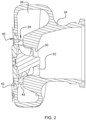
FIG. 2 is a cross-sectional view through the turbine assembly of the turbocharger, along line 2-2 inFIG. 1 ; -
FIG. 3 is an exploded view of the turbocharger ofFIG. 1 ; -
FIG. 4 is an exploded view of a vane ring in accordance with embodiments of the invention; -
FIG. 5 is an isometric view of the vane ring after the vanes have been mated with the nozzle ring; -
FIG. 6 is another isometric view of the vane ring ofFIG. 5 ; -
FIG. 7 is an axial view of the vane ring ofFIG. 5 ; -
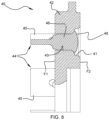
FIG. 8 is a cross-sectional view along line 8-8 inFIG. 7 , showing the vane shaft having been riveted to affix the vane shaft to the nozzle ring; -
FIG. 9 is an exploded view showing a vane-setting fixture into which the vanes are fitted to set them at the correct setting angles and locations, and also showing the nozzle ring and vanes to be placed into the fixture; -
FIG. 10 is a view similar toFIG. 9 , showing the vanes having been inserted into the vane-receiving slots in the base of the fixture; -
FIG. 11 is a view similar toFIGS. 9 and10 , showing the nozzle ring mated with the vanes in the fixture; and -
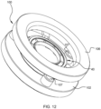
FIG. 12 is an isometric view of the fixture closed to capture the nozzle ring and vanes in preparation for affixing of the vane shafts to the nozzle ring. - The present disclosure will now be described in fuller detail with reference to the above-described drawings, which depict some but not all embodiments of the invention(s) to which the present disclosure pertains. These inventions may be embodied in various forms, including forms not expressly described herein, and should not be construed as limited to the particular exemplary embodiments described herein. In the following description, like numbers refer to like elements throughout.
-
FIGS. 1-3 illustrate aturbocharger 10 according to one exemplary embodiment of the invention. The turbocharger includes a compressor 12 (FIG. 3 ) comprising a compressor wheel (not visible) mounted within acompressor housing 16, for receiving air and compressing the air so that it can be fed to the intake of an internal combustion engine. The turbocharger further comprises a turbine comprising aturbine wheel 22 mounted within aturbine housing 24 and connected by a rotary shaft to the compressor wheel. Acenter housing 20 contains bearings for the rotary shaft. The turbine housing defines anexhaust gas inlet 25 and anannular chamber 26 that surrounds theturbine wheel 24. Exhaust gases from the internal combustion engine are fed through the exhaust gas inlet into the annular chamber. The turbine housing defines a nozzle 28 (FIG. 2 ) that directs exhaust gases from the annular chamber generally radially inwardly to theturbine wheel 22, and as the gases are expanded in their passage through the turbine wheel, the turbine wheel is rotatably driven, thereby driving the compressor wheel to compress the air for the engine. After passing through the turbine wheel, the exhaust gases are discharged out from abore 30 in the turbine housing and then proceed through an exhaust system for the engine. - As seen in
FIG. 2 , theturbine nozzle 28 includes avane ring 40 comprising anannular nozzle ring 42 and a plurality ofvanes 44 affixed to the nozzle ring. The vanes extend across the turbine nozzle and the exhaust gases pass through the vane passages, which guide and regulate the flow of exhaust gases to the turbine wheel. - In accordance with conventional fixed-vane rings of the prior art, the
nozzle ring 42 andvanes 44 comprise a monolithic part formed by casting (or alternatively by CNC machining of a billet or blank). A drawback of the conventional casting process is that a modification to the turbocharger design usually necessitates a modification to the vane ring configuration as well, such as a change in the setting angles of the vanes. Accordingly, an entirely new set of mold tooling for casting must be designed and built, which is a relatively expensive endeavor. Similarly, changing a machined vane ring configuration necessitates rewriting the CNC control instructions, which also is a relatively involved and expensive process. -
FIGS. 4 through 12 illustrate methods for constructing a vane ring in accordance with the invention, which can facilitate design changes in a relatively quick and simple manner. The method comprises providing anozzle ring 42 comprising an annular flat disk, the nozzle ring having a first face F1 (FIG. 7 ) and an opposite second face F2 (FIG. 6 ; see alsoFIG. 8 ). The method includes forming a plurality of circumferentially spaced circular bores 43 extending through the nozzle ring from the first face to the second face (FIGS. 4 and8 ). A plurality ofvanes 44 are provided, each vane comprising anairfoil portion 45 and acircular vane shaft 46 extending from one end of the airfoil portion of the vane. The method further comprises inserting thevane shafts 46 respectively into thebores 43 in the nozzle ring from said first face thereof (FIG. 5 ) so that the distal ends of the vane shafts are accessible at the second face of the nozzle ring. The vanes are oriented rotationally (with respect to the axis of rotation of each vane shaft) at a desired setting angle β for each vane (FIG. 7 ). Then, thevane shafts 46 are rigidly affixed to thenozzle ring 42 to fix the vanes at the desired setting angles and prevent relative motion between the vanes and the nozzle ring. - In accordance with a first embodiment of the invention as shown in
FIGS. 6 and8 , the rigid fixing of the vane shafts is accomplished by riveting the distal ends of the vane shafts, i.e., upsetting the ends of the shafts to form enlarged heads 48. Advantageously, a recessed area orgroove 41 is formed in the second face F2 of the nozzle ring for accommodating theenlarged heads 48 so that the heads do not protrude farther than the non-recessed portion of the second face of the nozzle ring, as best seen inFIG. 8 . This helps to protect the riveted heads of the vane shafts. - A method in accordance with a second embodiment of the invention is generally similar to that of the first embodiment, except instead of riveting the
vane shafts 46, the vane shafts are affixed to the nozzle ring via welds. Any suitable welding process can be used, such as laser welding. -
FIGS. 9-12 illustrate an optional (although advantageous) mode of practicing the invention in which afixture 100 is employed to facilitate arranging all the vanes at their proper setting angles and locations. The fixture comprises a base 102 that defines a generally planar upper surface in which a plurality of vane-receivingslots 104 are defined. The slots are configured to receive theairfoil portions 45 of thevanes 44 and orient the airfoil portions at the desired setting angles; thevane shafts 46 project upwardly with respect to the horizontally oriented base (FIG. 10 ). The fixture includes acover 106 that includes a plurality of posts orlegs 107, which are received into correspondingreceptacles 103 in the base. After the vanes are inserted in the slots in the base, thenozzle ring 42 is placed onto the vanes, thevane shafts 46 being received into thebores 43 in the nozzle ring as shown inFIG. 11 . Thecover 106 is then mated with the base (FIG. 12 ) to capture thevane ring 40 within the fixture. The vane ring is then ready for the next step of affixing the vane shafts to the nozzle ring via riveting or welding or any other suitable technique. - The invention facilitates a number of advantages over conventional vane ring fabrication processes. As noted, vane rings of various configurations can be constructed from the same configuration of nozzle ring and vanes. For example, it is a simple matter to produce a new vane ring design having the vane setting angles modified as required, using the identically same nozzle ring and vane configurations. Another potential advantage is the ability to make the nozzle ring from one material and the vanes from another different material, something that is not possible by casting or CNC machining methods.
- Persons skilled in the art, on the basis of the present disclosure, will recognize that modifications and other embodiments of the inventions described herein can be made without departing from the inventive concepts described herein. Specific terms used herein are employed for explanatory purposes rather than purposes of limitation. Accordingly, the inventions are not to be limited to the specific embodiments disclosed, and modifications and other embodiments are intended to be included within the scope of the appended claims.
Claims (5)
- A method for constructing a fixed-vane ring for a nozzle of a turbocharger turbine, comprising the steps of:providing a nozzle ring comprising an annular flat disk, the nozzle ring having a first face and an opposite second face;forming a plurality of circumferentially spaced circular bores extending through the nozzle ring from the first face to the second face;providing a plurality of vanes, each vane comprising an airfoil portion and a circular vane shaft extending from one end of the airfoil portion;inserting the vane shafts respectively into the bores in the nozzle ring from said first face thereof, each vane being oriented at a desired setting angle; andrigidly affixing the vane shafts to the nozzle ring to fix the vanes at the desired setting angles.
- The method of claim 1, wherein the rigidly affixing step comprises riveting the vane shafts to the nozzle ring.
- The method of any preceding claim, wherein the rigidly affixing step comprises welding the vane shafts to the nozzle ring.
- The method of any preceding claim, wherein the nozzle ring is provided to be constructed of a first material, and the vanes are provided to be constructed of a second material that is different from the first material.
- The method of any preceding claim, wherein the nozzle ring is provided to have an annular groove formed in the second face, the bores being located within said annular groove.
Applications Claiming Priority (1)
| Application Number | Priority Date | Filing Date | Title |
|---|---|---|---|
| US17/653,110 US11530615B1 (en) | 2022-03-01 | 2022-03-01 | Method for constructing a fixed-vane ring for a nozzle of a turbocharger turbine |
Publications (3)
| Publication Number | Publication Date |
|---|---|
| EP4239164A2 true EP4239164A2 (en) | 2023-09-06 |
| EP4239164A3 EP4239164A3 (en) | 2023-09-13 |
| EP4239164B1 EP4239164B1 (en) | 2026-04-15 |
Family
ID=84044123
Family Applications (1)
| Application Number | Title | Priority Date | Filing Date |
|---|---|---|---|
| EP22203979.4A Active EP4239164B1 (en) | 2022-03-01 | 2022-10-26 | Method for constructing a fixed-vane ring for a nozzle of a turbocharger turbine |
Country Status (3)
| Country | Link |
|---|---|
| US (1) | US11530615B1 (en) |
| EP (1) | EP4239164B1 (en) |
| CN (1) | CN116357409A (en) |
Family Cites Families (42)
| Publication number | Priority date | Publication date | Assignee | Title |
|---|---|---|---|---|
| US953526A (en) * | 1907-10-12 | 1910-03-29 | Westinghouse Machine Co | Elastic-fluid turbine. |
| US961329A (en) * | 1910-03-19 | 1910-06-14 | Henry H Wait | Turbine-blade. |
| US1158755A (en) * | 1914-07-23 | 1915-11-02 | Joseph Briggs Weaver | Method of marking, punching, and assembling shroud-bands for turbine-blades. |
| US1470507A (en) * | 1921-02-16 | 1923-10-09 | Gen Electric | Method of making rotor elements for elastic-fluid turbines |
| US1497081A (en) * | 1923-03-20 | 1924-06-10 | Midwest Engine Corp | Turbine nozzle blade and mounting therefor |
| US1717203A (en) * | 1926-02-20 | 1929-06-11 | Gen Electric | Bladed-turbine structure |
| US2417486A (en) * | 1943-02-19 | 1947-03-18 | Allis Chalmers Mfg Co | Nozzle construction |
| US2739782A (en) * | 1952-10-07 | 1956-03-27 | Fairchild Engine & Airplane | Variable area turbine nozzle |
| CH331658A (en) * | 1955-02-17 | 1958-07-31 | Buechi Alfred J Dipl Ing | Guide device on flow machines |
| US3038698A (en) * | 1956-08-30 | 1962-06-12 | Schwitzer Corp | Mechanism for controlling gaseous flow in turbo-machinery |
| US3802046A (en) * | 1972-01-27 | 1974-04-09 | Chromalloy American Corp | Method of making or reconditioning a turbine-nozzle or the like assembly |
| US4575911A (en) * | 1985-02-08 | 1986-03-18 | Abdite Industries, Inc. | Method and apparatus for constructing turbine components |
| US5207559A (en) * | 1991-07-25 | 1993-05-04 | Allied-Signal Inc. | Variable geometry diffuser assembly |
| US6419464B1 (en) * | 2001-01-16 | 2002-07-16 | Honeywell International Inc. | Vane for variable nozzle turbocharger |
| US20040213665A1 (en) * | 2001-05-10 | 2004-10-28 | Shinjiro Ohishi | Exhaust gas assembly with improved heat resistance for vgs turbocharger, method for manufacturing heat resisting member applicable thereto, and method for manufacturing shaped material for adjustable blade applicable thereto |
| CN1293291C (en) * | 2001-08-03 | 2007-01-03 | 株式会社秋田精密冲压 | Variable blade manufacturing method and variable blade in VGS type turbo charger |
| FR2853000B1 (en) * | 2003-03-25 | 2007-05-04 | Snecma Moteurs | COOLING AIR INJECTION DEVICE IN A TURBINE ROTOR |
| EP1528225B1 (en) * | 2003-10-27 | 2006-08-16 | BorgWarner Inc. | Turbomachine and production method for a stator assembly |
| CN201080832Y (en) * | 2007-07-11 | 2008-07-02 | 周彦学 | Variable section worm supercharger |
| US9017017B2 (en) * | 2009-04-10 | 2015-04-28 | Honeywell Internatonal Inc. | Variable-vane assembly having fixed guide pins for unison ring |
| US8668443B2 (en) * | 2010-01-08 | 2014-03-11 | Honeywell International Inc. | Variable-vane assembly having unison ring guided radially by rollers and fixed members, and restrained axially by one or more fixed axial stops |
| GB2481245A (en) * | 2010-06-18 | 2011-12-21 | Cummins Turbo Tech Ltd | Variable geometry turbine |
| US8616836B2 (en) * | 2010-07-19 | 2013-12-31 | Cameron International Corporation | Diffuser using detachable vanes |
| US8511981B2 (en) * | 2010-07-19 | 2013-08-20 | Cameron International Corporation | Diffuser having detachable vanes with positive lock |
| DE102011075794A1 (en) * | 2011-05-13 | 2012-11-15 | Bosch Mahle Turbo Systems Gmbh & Co. Kg | Variable turbine / compressor geometry |
| DE102012001236B4 (en) * | 2012-01-18 | 2024-10-24 | Ihi Charging Systems International Gmbh | guide device for a turbine of an exhaust gas turbocharger |
| ITCO20120014A1 (en) * | 2012-04-06 | 2013-10-07 | Nuovo Pignone Srl | DIAPHRAGM RING OF STATHY STAKE, STEAM TURBINE AND METHOD |
| EP2733311B1 (en) * | 2012-11-16 | 2019-01-02 | ABB Turbo Systems AG | Nozzle ring |
| KR102077734B1 (en) * | 2013-01-14 | 2020-02-14 | 보르그워너 인코퍼레이티드 | Split nozzle ring to control egr and exhaust flow |
| CA2899891A1 (en) * | 2013-03-14 | 2014-10-02 | Adam L. CHAMBERLAIN | Bi-cast turbine vane |
| GB2513666B (en) * | 2013-05-03 | 2015-07-15 | Dyson Technology Ltd | Compressor |
| US9938894B2 (en) * | 2015-05-06 | 2018-04-10 | Honeywell International Inc. | Turbocharger with variable-vane turbine nozzle having a bypass mechanism integrated with the vanes |
| CN107035427B (en) * | 2017-04-11 | 2023-02-28 | 奕森科技(江苏)有限公司 | Variable nozzle assembly of turbocharger and assembly method thereof |
| DE102017108057A1 (en) * | 2017-04-13 | 2018-10-18 | Abb Turbo Systems Ag | NOZZLE RING FOR AN ABGASTURBOLADER |
| US10844465B2 (en) * | 2017-08-09 | 2020-11-24 | Garrett Transportation I Inc. | Stainless steel alloys and turbocharger kinematic components formed from stainless steel alloys |
| CN207454034U (en) * | 2017-10-24 | 2018-06-05 | 奕森科技(上海)有限公司 | A kind of synchronous ring structure for nozzle assembly |
| CN108775261B (en) * | 2018-03-26 | 2020-02-21 | 北京理工大学 | A turbocharger with adjustable guide vane structure of radial turbine nozzle ring |
| US11248488B2 (en) * | 2019-03-12 | 2022-02-15 | Garrett Transportation I Inc. | Method for making a twin-vaned nozzle ring assembly for a turbocharger with twin-scroll turbine housing for directing exhaust gases from each scroll onto turbine wheel in interleaved fashion |
| US11085311B2 (en) * | 2019-03-12 | 2021-08-10 | Garrett Transportation I Inc. | Turbocharger with twin-scroll turbine housing and twin vaned nozzle ring for directing exhaust gases from each scroll onto turbine wheel in interleaved fashion |
| US10927702B1 (en) * | 2019-03-30 | 2021-02-23 | Savant Holdings LLC | Turbocharger or turbocharger component |
| EP3741960B1 (en) * | 2019-05-24 | 2023-11-01 | Garrett Transportation I Inc. | Method for making a twin-vaned nozzle ring assembly for a turbocharger |
| US11668201B2 (en) * | 2020-09-08 | 2023-06-06 | Borgwarner Inc. | Entryway system including a divided volute turbocharger having variable turbine geometry with aerodynamic spacers and vane ring with plurality of rotatable vanes |
-
2022
- 2022-03-01 US US17/653,110 patent/US11530615B1/en active Active
- 2022-10-26 EP EP22203979.4A patent/EP4239164B1/en active Active
- 2022-12-30 CN CN202211742187.3A patent/CN116357409A/en active Pending
Also Published As
| Publication number | Publication date |
|---|---|
| EP4239164A3 (en) | 2023-09-13 |
| US11530615B1 (en) | 2022-12-20 |
| EP4239164B1 (en) | 2026-04-15 |
| CN116357409A (en) | 2023-06-30 |
Similar Documents
| Publication | Publication Date | Title |
|---|---|---|
| JP5181114B2 (en) | High pressure ratio rear fan assembly and gas turbine engine | |
| US7195447B2 (en) | Gas turbine engine and method of assembling same | |
| US10900415B2 (en) | Turbocharger having a meridionally divided turbine housing and a variable turbine nozzle | |
| US9909456B2 (en) | Nozzle ring | |
| EP3401505B1 (en) | Turbocharger having a meridionally divided turbine housing and a variable turbine nozzle | |
| US20100260597A1 (en) | Variable-vane assembly having fixed guide pins for unison ring | |
| US8864458B2 (en) | Fixed vane assembly for a turbine engine having a reduced weight, and turbine engine comprising at least one such fixed vane assembly | |
| JP2004332737A (en) | Method and apparatus for controlling tip clearance of a gas turbine engine rotor | |
| EP3741960B1 (en) | Method for making a twin-vaned nozzle ring assembly for a turbocharger | |
| US11248488B2 (en) | Method for making a twin-vaned nozzle ring assembly for a turbocharger with twin-scroll turbine housing for directing exhaust gases from each scroll onto turbine wheel in interleaved fashion | |
| US7980816B2 (en) | Retainer for a turbocharger | |
| US5299910A (en) | Full-round compressor casing assembly in a gas turbine engine | |
| US11530615B1 (en) | Method for constructing a fixed-vane ring for a nozzle of a turbocharger turbine | |
| EP4067626B1 (en) | Turbocharger with vaned turbine nozzle and method of assembling same | |
| JP5072207B2 (en) | Turbine module for a gas turbine engine having a rotor including a monoblock body | |
| US7934901B2 (en) | Air directing assembly and method of assembling the same | |
| US10830441B2 (en) | Swirler for a turbine engine combustor | |
| US12000293B1 (en) | Systems and methods for multi-dimensional variable vane stage rigging utilizing coupling mechanisms | |
| US11725525B2 (en) | Engine section stator vane assembly with band stiffness features for turbine engines | |
| US11834966B1 (en) | Systems and methods for multi-dimensional variable vane stage rigging utilizing adjustable alignment mechanisms | |
| US12331660B1 (en) | Vane assemblies with overlapping band couplings in gas turbine engines | |
| US11959389B2 (en) | Turbine shroud segments with angular locating feature |
Legal Events
| Date | Code | Title | Description |
|---|---|---|---|
| PUAI | Public reference made under article 153(3) epc to a published international application that has entered the european phase |
Free format text: ORIGINAL CODE: 0009012 |
|
| STAA | Information on the status of an ep patent application or granted ep patent |
Free format text: STATUS: REQUEST FOR EXAMINATION WAS MADE |
|
| PUAL | Search report despatched |
Free format text: ORIGINAL CODE: 0009013 |
|
| 17P | Request for examination filed |
Effective date: 20221026 |
|
| AK | Designated contracting states |
Kind code of ref document: A2 Designated state(s): AL AT BE BG CH CY CZ DE DK EE ES FI FR GB GR HR HU IE IS IT LI LT LU LV MC ME MK MT NL NO PL PT RO RS SE SI SK SM TR |
|
| AK | Designated contracting states |
Kind code of ref document: A3 Designated state(s): AL AT BE BG CH CY CZ DE DK EE ES FI FR GB GR HR HU IE IS IT LI LT LU LV MC ME MK MT NL NO PL PT RO RS SE SI SK SM TR |
|
| RIC1 | Information provided on ipc code assigned before grant |
Ipc: F01D 9/04 20060101AFI20230809BHEP |
|
| P01 | Opt-out of the competence of the unified patent court (upc) registered |
Effective date: 20231110 |
|
| GRAP | Despatch of communication of intention to grant a patent |
Free format text: ORIGINAL CODE: EPIDOSNIGR1 |
|
| STAA | Information on the status of an ep patent application or granted ep patent |
Free format text: STATUS: GRANT OF PATENT IS INTENDED |
|
| GRAJ | Information related to disapproval of communication of intention to grant by the applicant or resumption of examination proceedings by the epo deleted |
Free format text: ORIGINAL CODE: EPIDOSDIGR1 |
|
| STAA | Information on the status of an ep patent application or granted ep patent |
Free format text: STATUS: REQUEST FOR EXAMINATION WAS MADE |
|
| INTG | Intention to grant announced |
Effective date: 20251017 |
|
| INTC | Intention to grant announced (deleted) | ||
| GRAP | Despatch of communication of intention to grant a patent |
Free format text: ORIGINAL CODE: EPIDOSNIGR1 |
|
| STAA | Information on the status of an ep patent application or granted ep patent |
Free format text: STATUS: GRANT OF PATENT IS INTENDED |
|
| INTG | Intention to grant announced |
Effective date: 20251210 |
|
| GRAS | Grant fee paid |
Free format text: ORIGINAL CODE: EPIDOSNIGR3 |
|
| GRAA | (expected) grant |
Free format text: ORIGINAL CODE: 0009210 |
|
| STAA | Information on the status of an ep patent application or granted ep patent |
Free format text: STATUS: THE PATENT HAS BEEN GRANTED |
|
| AK | Designated contracting states |
Kind code of ref document: B1 Designated state(s): AL AT BE BG CH CY CZ DE DK EE ES FI FR GB GR HR HU IE IS IT LI LT LU LV MC ME MK MT NL NO PL PT RO RS SE SI SK SM TR |
|
| REG | Reference to a national code |
Ref country code: CH Ref legal event code: F10 Free format text: ST27 STATUS EVENT CODE: U-0-0-F10-F00 (AS PROVIDED BY THE NATIONAL OFFICE) Effective date: 20260415 |
|
| REG | Reference to a national code |
Ref country code: DE Ref legal event code: R096 Ref document number: 602022034507 Country of ref document: DE |