EP4238886B1 - Gland anti-pinch device and apparatus having gland - Google Patents
Gland anti-pinch device and apparatus having gland Download PDFInfo
- Publication number
- EP4238886B1 EP4238886B1 EP22874331.6A EP22874331A EP4238886B1 EP 4238886 B1 EP4238886 B1 EP 4238886B1 EP 22874331 A EP22874331 A EP 22874331A EP 4238886 B1 EP4238886 B1 EP 4238886B1
- Authority
- EP
- European Patent Office
- Prior art keywords
- support
- press cover
- reset member
- locking
- pinch device
- Prior art date
- Legal status (The legal status is an assumption and is not a legal conclusion. Google has not performed a legal analysis and makes no representation as to the accuracy of the status listed.)
- Active
Links
Images




Classifications
-
- F—MECHANICAL ENGINEERING; LIGHTING; HEATING; WEAPONS; BLASTING
- F16—ENGINEERING ELEMENTS AND UNITS; GENERAL MEASURES FOR PRODUCING AND MAINTAINING EFFECTIVE FUNCTIONING OF MACHINES OR INSTALLATIONS; THERMAL INSULATION IN GENERAL
- F16B—DEVICES FOR FASTENING OR SECURING CONSTRUCTIONAL ELEMENTS OR MACHINE PARTS TOGETHER, e.g. NAILS, BOLTS, CIRCLIPS, CLAMPS, CLIPS OR WEDGES; JOINTS OR JOINTING
- F16B9/00—Connections of rods or tubular parts to flat surfaces at an angle
- F16B9/05—Connections of rods or tubular parts to flat surfaces at an angle by way of an intermediate member
-
- F—MECHANICAL ENGINEERING; LIGHTING; HEATING; WEAPONS; BLASTING
- F16—ENGINEERING ELEMENTS AND UNITS; GENERAL MEASURES FOR PRODUCING AND MAINTAINING EFFECTIVE FUNCTIONING OF MACHINES OR INSTALLATIONS; THERMAL INSULATION IN GENERAL
- F16P—SAFETY DEVICES IN GENERAL; SAFETY DEVICES FOR PRESSES
- F16P3/00—Safety devices acting in conjunction with the control or operation of a machine; Control arrangements requiring the simultaneous use of two or more parts of the body
- F16P3/12—Safety devices acting in conjunction with the control or operation of a machine; Control arrangements requiring the simultaneous use of two or more parts of the body with means, e.g. feelers, which in case of the presence of a body part of a person in or near the danger zone influence the control or operation of the machine
-
- F—MECHANICAL ENGINEERING; LIGHTING; HEATING; WEAPONS; BLASTING
- F16—ENGINEERING ELEMENTS AND UNITS; GENERAL MEASURES FOR PRODUCING AND MAINTAINING EFFECTIVE FUNCTIONING OF MACHINES OR INSTALLATIONS; THERMAL INSULATION IN GENERAL
- F16P—SAFETY DEVICES IN GENERAL; SAFETY DEVICES FOR PRESSES
- F16P1/00—Safety devices independent of the control and operation of any machine
-
- F—MECHANICAL ENGINEERING; LIGHTING; HEATING; WEAPONS; BLASTING
- F16—ENGINEERING ELEMENTS AND UNITS; GENERAL MEASURES FOR PRODUCING AND MAINTAINING EFFECTIVE FUNCTIONING OF MACHINES OR INSTALLATIONS; THERMAL INSULATION IN GENERAL
- F16P—SAFETY DEVICES IN GENERAL; SAFETY DEVICES FOR PRESSES
- F16P3/00—Safety devices acting in conjunction with the control or operation of a machine; Control arrangements requiring the simultaneous use of two or more parts of the body
- F16P3/08—Safety devices acting in conjunction with the control or operation of a machine; Control arrangements requiring the simultaneous use of two or more parts of the body in connection with the locking of doors, covers, guards, or like members giving access to moving machine parts
-
- B—PERFORMING OPERATIONS; TRANSPORTING
- B30—PRESSES
- B30B—PRESSES IN GENERAL
- B30B15/00—Details of, or accessories for, presses; Auxiliary measures in connection with pressing
- B30B15/08—Accessory tools, e.g. knives; Mountings therefor
Definitions
- the present application relates to the field of press cover apparatuses, and in particular to a press cover anti-pinch device and an apparatus having a press cover.
- Examples of anti-pinch devices are shown in CN107310689A and CN205402530U .
- press cover apparatuses have been widely used in the field of production and processing.
- a user first opens a press cover to complete a corresponding operation and then closes the press cover.
- the press cover When the press cover is in an opened state, the hand of the user are located within a vertical projection area range of the press cover, and at this time, once the press cover is faulty and then falls down, the hand of the user will be pinched, so there is a potential safety hazard. Therefore, it is very necessary to provide a press cover anti-pinch device.
- a press cover anti-pinch device comprising:
- the connector and the support are provided, so that when the support is arranged in the supporting position, the support swings down and supports the press cover on the supporting surface, and when the support is arranged in the collapsed position, the support is collapsed and the press cover is lowered.
- the support swings down and supports the press cover on the supporting surface, so that the support provides a supporting force to the press cover, and when the hand of the user perform an operation within a projection area range of the press cover, the press cover cannot fall down even if the press cover is faulty, effectively ensuring the safety of the user during the operation.
- the support is arranged in the collapsed position, and at this time, the support is collapsed and the press cover is lowered for a next operation.
- the press cover anti-pinch device further comprises: a locking mechanism arrangeable in a locking position or in an unlocking position, wherein when the locking mechanism is arranged in the locking position, the support is locked in the supporting position and/or the collapsed position, and when the locking mechanism is arranged in the unlocking position, the support is rotatable to another position other than the locking position.
- a locking mechanism arrangeable in a locking position or in an unlocking position, wherein when the locking mechanism is arranged in the locking position, the support is locked in the supporting position and/or the collapsed position, and when the locking mechanism is arranged in the unlocking position, the support is rotatable to another position other than the locking position.
- the locking mechanism comprises: a reset member configured to automatically reset the locking mechanism from the unlocking position to the locking position when the support is arranged in the supporting position and/or the collapsed position. Providing the reset member enables the locking mechanism to be automatically reset from the unlocking position to the locking position when the support is rotated to the supporting position and/or the collapsed position, so that the operation is more convenient and faster.
- the reset member is a gravitational reset member or an elastic reset member.
- the gravitational reset member automatically resets the locking mechanism from the unlocking position to the locking position by means of a downward movement due to its own gravity; and the elastic reset member automatically resets the locking mechanism from the unlocking position to the locking position by means of the action of an elastic potential energy.
- Configuring the reset member as the gravitational reset member or the elastic reset member can better meet the requirements of different application scenarios.
- the reset member is hinged to the connector or the support, and swings down by means of its own gravity to automatically reset the locking mechanism to the locking position.
- the locking mechanism is in the unlocking position, and the reset member is risen up under the pressure of the support; and when the support is rotated to the supporting position and/or the collapsed position, the reset member swings down by means of its own gravity to automatically reset the locking mechanism to the locking position so as to ensure that the locking mechanism locks the support in the supporting position and/or the collapsed position.
- Providing the reset member hinged to the connector or the support enables switching between the locking position and the unlocking position of the locking mechanism to be more convenient and faster.
- the press cover anti-pinch device further comprises: an unlocking trigger arranged in a contact position and configured to unlock the locking mechanism from the locking position to the unlocking position when the reset member comes into contact with the unlocking trigger.
- an unlocking trigger arranged in a contact position and configured to unlock the locking mechanism from the locking position to the unlocking position when the reset member comes into contact with the unlocking trigger.
- the contact position is a position where the reset member comes into contact with the unlocking trigger when the press cover is lowered.
- the reset member comes into contact with the unlocking trigger in the contact position, so that the locking mechanism is unlocked from the locking position to the unlocking position under the action of the reset member, and at this time, the support is switched from the locked state to the rotatable state, thereby ensuring that when the press cover is risen, the support can swing down and support the press cover on the supporting surface during the next operation.
- Setting the contact position as the position where the reset member comes into contact with the unlocking trigger when the press cover is lowered can ensure that the support is automatically switched to the rotatable state when the press cover is lowered, so that the operation is more convenient during next use.
- the locking mechanism comprises: a first locking structure arranged on or connected to the connector and having a first engagement portion; and a second locking structure arranged on or connected to the support and having a second engagement portion adapted to the first engagement portion, wherein when the support is arranged in the supporting position and/or the collapsed position, the first engagement portion is engaged with the second engagement portion.
- the engagement between the first locking structure and the second locking structure to lock the support in the supporting position and/or the collapsed position can prevent the support from moving in the supporting position and/or the collapsed position, improving the safety of the operation.
- the first engagement portion and the second engagement portion are separated from each other, namely, when the locking mechanism is in the unlocking position, the support is in the rotatable state again, and state switching is convenient and free.
- the connector or the support has a curved surface portion with a hinged shaft as a central axis at the end where the connector is hinged to the support, and the first engagement portion or the second engagement portion is arranged on the curved surface portion.
- the locking mechanism further comprises: a reset member hinged to the connector or the support and configured to automatically reset the locking mechanism from the unlocking position to the locking position when the support is arranged in the supporting position and/or the collapsed position, the reset member having the first locking structure or the second locking structure.
- the first locking structure or the second locking structure is arranged on the reset member, such that when the support is in the supporting position and/or the collapsed position, the support is locked by means of the engagement between the locking structure on the reset member and the locking structure on the support; and when the locking structure on the reset member is separated from the locking structure on the support, the support is in the rotatable state again, so that the two states of the support are free to switch, and the operation is more convenient and faster.
- one end of the reset member is hinged to the connector, the other end thereof is a movable end, the first locking structure is arranged on the reset member, and the first engagement portion is arranged between the hinged end and the movable end of the connector; and the unlocking position of the unlocking trigger is arranged in a path along which the movable end of the reset member is lowered with the press cover.
- the unlocking position of the unlocking trigger is arranged in the path along which the movable end of the reset member is lowered with the press cover, when the press cover is lowered, the movable end is driven to lower therewith, and when the movable end is lowered to the unlocking position of the unlocking trigger, the unlocking trigger applies an upward reaction force to the movable end of the reset member, so that the first engagement portion and the second engagement portion are separated from each other to ensure that the support is in the rotatable state when being collapsed for next use.
- the reset member is arranged transversely.
- the reset member is arranged transversely, so that it can be ensured that the movable end of the reset member can easily come into contact with the unlocking trigger during the lowering of the reset member with the press cover.
- the support swings down to the supporting position by means of its own gravity. Since the connector is arranged at the lower side of the cover body of the press cover and the support is in turn hinged to the connector, during rising, the cover body of the press cover drives the connector to rise, and due to the action of gravity, the support swings down to the supporting position, so as to support the cover body of the press cover. With such an arrangement, it can be ensured that when the cover body is risen to a certain height, the support automatically swings down to the supporting position for providing a support function to the cover body, further improving the safety of production operation.
- a handle structure for an operator to apply a force is arranged on the support. After use, the operator can apply an acting force to the support in a rotation direction by means of the handle structure, so that the support is removed from the supporting position, the press cover is then lowered, and the support is collapsed for next use.
- the inventors further provide an apparatus having a press cover, the press cover being openable or closable, and a press cover anti-pinch device as described in the first aspect being arranged at a lower side of the press cover.
- the apparatus having the press cover in the present application comprises the press cover and the press cover anti-pinch device
- the support in the press cover anti-pinch device can be in the supporting position after the press cover is risen to support the cover body of the press cover, preventing the cover body from suddenly falling down to hurt an operator due to a fault, and effectively ensuring the safety of the operator during operation.
- the apparatus is a tank-type apparatus.
- the tank-type apparatus is often used in daily production and processing. Arranging the press cover anti-pinch device in the tank-type apparatus can cover more operation scenarios as much as possible to ensure the safety of an operator during operation.
- a plurality of means two or more (including two), similarly the term “a plurality of groups” means two or more groups (including two groups), and the term “a plurality of pieces” means two or more pieces (including two pieces).
- the technical terms “mounting”, “mutual connection”, “connection”, “fixing”, etc. should be understood in a broad sense, for example, they may be a fixed connection, a detachable connection, or an integrated connection; may be a mechanical connection or an electrical connection; and may be a direct connection or an indirect connection through an intermediate medium, and may be communication between interiors of two elements or interaction between the two elements.
- mounting may be a fixed connection, a detachable connection, or an integrated connection
- the specific meaning of the above terms in the embodiments of the present application can be understood according to specific situations.
- a press cover apparatus has been widely used in the field of production and processing.
- the press cover apparatuses has a cover body, which needs to be opened during operation and is closed after an operator finishes the operation.
- the cover body of the press cover apparatus may also be opened or closed in an electric-motor-driven, hydraulically-driven, or cylinder-driven manner, etc.
- the cover body is risen to a certain height in an opened state, and the operator needs to extend the hand into a vertical projection area range of the cover body during operation. If the cover body falls down suddenly due to a fault at this time, the hand of the operator will be pinched and hurt, so there is a potential safety hazard.
- the operator often uses one or more support rods to support the cover body, one end of the support rod abutting against a lower surface of the cover body, and the other end thereof abutting against a contact surface.
- the inventors have noted that the support rod will be relatively moved on the contact surface if it is subjected to an external force, and once the support rod is moved, the support rod is very prone to being removed from a supporting state due to the action of gravity of the cover body, and if the operator is operating at this time, the cover body suddenly falling down will directly pinch and hurt the hand of the operator, so there is still a great potential safety hazard in the manner of using only the support rod to support the opened cover body.
- the inventors designed a press cover anti-pinch device, so that a support 3 can have a better stability when supporting the press cover, preventing the cover body suddenly falling down from directly pinching the hand of the operator.
- the press cover anti-pinch device includes a connector 2 and a support 3.
- the connector 2 is arranged at a lower side of a cover body 1 of a press cover and is fixed to the press cover.
- the support 3 is hinged to the connector 2 and is rotatably arranged in a supporting position or in a collapsed position. When the support 3 is arranged in the supporting position, the support 3 swings down and supports the press cover on a supporting surface 11, and when the support 3 is arranged in the collapsed position, the support 3 is collapsed and the press cover is lowered.
- the supporting position refers to a position where the support 3 is located when the support 3 plays a supporting role, and is preferably a vertical position perpendicular to the lower surface of the cover body 1 of the press cover, but may also be a position at other angles to the lower surface of the cover body 1 of the press cover.
- the position can be referred to as the supporting position.
- the collapsed position is named relative to the supporting position, and when the support 3 is in the supporting position, the support 3 applies a supporting force to the lower surface of the cover body 1 of the press cover, so that the cover body 1 of the press cover cannot fall down.
- the support 3 when it is required to lower the press cover, it is necessary to remove the support 3 from the supporting position, and the support 3 is rotated, after being removed from the supporting position, to a position allowing the cover body 1 of the press cover to be lowered, which is referred to as the collapsed position.
- the collapsed position is preferably set horizontally relative to the lower surface of the press cover, but may also be a position at other angles to the lower surface of the cover body 1 of the press cover.
- the position when the support 3 is rotated, after being removed from the supporting position, to a position where the support 3 no longer supports the cover body 1 of the press cover, and the cover body 1 of the press cover can be lowered, the position can be referred to as the collapsed position.
- the press cover anti-pinch device includes the connector 2 and the support 3, wherein when the support 3 is arranged in the supporting position, the support 3 swings down and supports the press cover on the supporting surface 11, and when the support 3 is arranged in the collapsed position, the support 3 is collapsed and the press cover is lowered.
- the support 3 swings down and supports the press cover on the supporting surface 11, so that the support 3 provides a supporting force to the press cover, and when the hand of a user perform an operation within a projection area range of the press cover, the press cover cannot fall down even if the press cover is faulty, effectively ensuring the safety of a user during the operation.
- the support 3 When the operation is completed, the support 3 is arranged in the collapsed position, and at this time, the support 3 is collapsed and the press cover is lowered for a next operation. Since the support 3 is hinged to the connector 2 and the connector 2 is in turn fixed to the lower side of the cover body 1 of the press cover, the support 3 cannot relatively move when the support 3 is in the supporting position, improving the safety of the operation.
- the press cover anti-pinch device further includes a locking mechanism 4.
- the locking mechanism 4 is arrangeable in a locking position or in an unlocking position, wherein when the locking mechanism 4 is arranged in the locking position, the support 3 is locked in the supporting position and/or the collapsed position, and when the locking mechanism 4 is arranged in the unlocking position, the support 3 is rotatable to another position other than the locking position. Providing the locking mechanism 4 enables the support 3 to be in a locked state when located in the supporting position and/or the collapsed position, avoiding relative sliding and further improving the safety of the operation.
- the locking position refers to a position in the locked state, and when the locking mechanism 4 is in the locking position, the support 3 is locked in the supporting position and/or the collapsed position, so as to avoid the relative movement of the support 3 in the supporting position and/or the collapsed position, further improving the stability of the support 3.
- the unlocking position refers to a position in an unlocked state, and when the locking mechanism 4 is in the unlocking position, the support 3 is in a rotatable state and can be rotated to another position other than the locking position.
- the locking mechanism 4 When the support 3 is in the supporting position, the locking mechanism 4 is in the unlocking position; and when the support 3 is in the collapsed position, the locking mechanism 4 is in the locking position. After the operation is finished, the operator can rotate the support 3 from the supporting position to the collapsed position so as to lower the press cover.
- the relationship between the support 3 and the locking mechanism 4 may also be set such that when the support 3 is in the supporting position, the locking mechanism 4 is in the locking position; and when the support 3 is in the collapsed position, the locking mechanism 4 is in the unlocking position.
- the relative sliding of the support 3 can be avoided, effectively improving the stability of the support 3 in the supporting position.
- the operator can first switch the locking mechanism 4 from the locking position to the unlocking position by adjusting the locking mechanism so that the support 3 is in the rotatable state, and the operator then rotates the support 3 from the supporting position to the collapsed position so as to lower the press cover to complete the operation.
- the relationship between the support 3 and the locking mechanism 4 may also be set such that when the support 3 is in the supporting position, the locking mechanism 4 is in the locking position; and when the support 3 is in the collapsed position, the locking mechanism 4 is in the locking position.
- the relative sliding of the support 3 in the supporting position and the collapsed position can be avoided, further improving the safety of the operation.
- the operator can first switch the locking mechanism from the locking position to the unlocking position by adjusting the locking mechanism so that the support 3 is in the rotatable state, the operator then rotates the support 3 from the supporting position to the collapsed position, and when the support 3 is in the collapsed position, the support 3 is locked again by the locking mechanism, so as to ensure that the support 3 cannot relatively move in the lowering process of the press cover, thus improving the safety of the operation.
- the locking mechanism is switched from the locking position to the unlocking position again so that the support 3 is in the rotatable state, so as to ensure normal use during the next operation.
- the locking mechanism 4 includes: a reset member 41.
- the reset member 41 is configured to automatically reset the locking mechanism from the unlocking position to the locking position when the support 3 is arranged in the supporting position and/or the collapsed position .
- Providing the reset member 41 enables the locking mechanism to be automatically reset from the unlocking position to the locking position when the support 3 is rotated to the supporting position and/or the collapsed position, so that the operation is more convenient and faster.
- the reset member 41 is a gravitational reset member or an elastic reset member.
- the gravitational reset member automatically resets the locking mechanism from the unlocking position to the locking position by means of a downward movement due to its own gravity; and the elastic reset member automatically resets the locking mechanism from the unlocking position to the locking position by means of the action of an elastic potential energy.
- Configuring the reset member as the gravitational reset member or the elastic reset member can better meet the requirements of different application scenarios.
- the reset member 41 in Figs. 1-4 is the gravitational reset member
- the reset member 41 in Figs. 9-12 is the elastic reset member
- the reset member 41 in Figs. 5-8 is a combination of the gravitational reset member and the elastic reset member.
- the reset member 41 is hinged to the connector 2 or the support 3, and swings down by means of its own gravity to automatically reset the locking mechanism to the locking position.
- the locking mechanism is in the unlocking position, and the reset member 41 is risen up under the pressure of the support 3; and when the support 3 is rotated to the supporting position and/or the collapsed position, the reset member 41 swings down by means of its own gravity to automatically reset the locking mechanism to the locking position so as to ensure that the locking mechanism locks the support 3 in the supporting position and/or the collapsed position.
- Providing the reset member 41 hinged to the connector 2 or the support 3 enables switching between the locking position and the unlocking position of the locking mechanism to be more convenient and faster.
- the reset member 41 may be a cross rod structure, and as shown in Figs. 9-12 , the reset member 41 may also be a cross rod structure. In some other embodiments, the reset member 41 may also be an L-shaped structure.
- the L-shaped structure includes a cross rod and a vertical rod, wherein a first locking structure 42 is arranged on the cross rod to fit with a second locking structure 32 on the support 3, thereby switching the locking mechanism between the locking position and the unlocking position, and a spring 412 connected to the support 3 is arranged on the vertical rod to automatically reset the locking mechanism to the locking position.
- the reset member 41 may also be of structures in other shapes, in short, any structure of the reset member 41 enabling the locking mechanism to be automatically reset to the locking position falls within the scope of protection of the embodiment.
- the press cover anti-pinch device further includes an unlocking trigger 5.
- the unlocking trigger 5 is arranged in a contact position and is configured to unlock the locking mechanism from the locking position to the unlocking position when the reset member 41 comes into contact with the unlocking trigger 5.
- the reset member 41 When it is required to switch the support 3 from the locked state to the rotatable state, it is only necessary to make the reset member 41 come into contact with the unlocking trigger 5, so that the reset member 41 unlocks the locking mechanism from the locking position to the unlocking position by means of a reset action, and at this time, the support 3 is switched from the locked state to the rotatable state.
- Providing the unlocking trigger 5 enables switching between the locking position and the unlocking position of the locking mechanism to be more convenient and faster, and thus switching from the locked state to the rotatable state of the support 3 to be more convenient and faster.
- the unlocking trigger 5 may be a trigger rod, a trigger block, etc., the unlocking trigger 5 may be arranged transversely or longitudinally, and the unlocking trigger 5 only needs to be capable of coming into contact with the reset member 41 and to be capable of unlocking the locking mechanism from the locking position to the unlocking position after the two comes into contact with each other. Any structure capable of meeting the functional requirement falls within the scope of protection of the embodiment. As shown in Figs. 1-12 , the unlocking trigger 5 is arranged longitudinally on a base 7.
- the contact position is a position where the reset member 41 comes into contact with the unlocking trigger when the press cover is lowered.
- the reset member 41 comes into contact with the unlocking trigger 5 in the contact position, so that the locking mechanism is unlocked from the locking position to the unlocking position under the action of the reset member 41, and at this time, the support 3 is switched from the locked state to the rotatable state, thereby ensuring that when the press cover is risen, the support 3 can swing down and support the press cover on the supporting surface 11 during the next operation.
- Setting the contact position as the position where the reset member 41 comes into contact with the unlocking trigger when the press cover is lowered can ensure that the support 3 is automatically switched to the rotatable state when the press cover is lowered, so that the operation is more convenient during next use.
- the locking mechanism 4 includes the first locking structure 42 and the second locking structure 32, wherein the first locking structure 42 is arranged on or connected to the connector 2 and has a first engagement portion, the second locking structure 32 is arranged on or connected to the support 3 and has a second engagement portion adapted to the first engagement portion, and when the support 3 is arranged in the supporting position and/or the collapsed position, the first engagement portion is engaged with the second engagement portion.
- the engagement between the first locking structure 42 and the second locking structure 32 to lock the support 3 in the supporting position and/or the collapsed position can prevent the support 3 from moving in the supporting position and/or the collapsed position, improving the safety of the operation.
- the first engagement portion and the second engagement portion are separated from each other, namely, when the locking mechanism is in the unlocking position, the support 3 is in the rotatable state again, and state switching is convenient and free.
- the first locking structure 42 may be arranged directly on the locking mechanism 4 and integrally formed with other components of the locking mechanism 4; or the first locking structure may be first arranged on a further component and is then connected to the connector 2 or the support 3 by means of the further component.
- the first locking structure 42 is first arranged on a connecting rod and is then connected to the connector 2 or the support 3 by means of the connecting rod.
- the engagement connection manner of the first engagement portion and the second engagement portion includes: various concave-convex fit structures such as a key and key groove fit connection, a protrusion and recess fit connection, and a two-boss fit structure (such as the fitting of a protrusion or a snap key, etc.). Any structure capable of achieving the engagement between the first engagement portion and the second engagement portion fall within the scope of protection of the embodiment.
- the connector 2 or the support 3 has a curved surface portion 31 with a hinged shaft as a central axis at the end where the connector 2 is hinged to the support 3, and the first engagement portion or the second engagement portion is arranged on the curved surface portion 31. In this way, when the support 3 is rotated to the supporting position and/or the collapsed position, the first engagement portion and the second engagement portion are automatically engaged closely, so that locking of the support 3 is more convenient and faster.
- the curved surface portion 31 may be in a shape of a variety of curved surfaces, such as a circular cylindrical surface, an elliptic cylindrical surface, or a parabolic surface.
- the curved surface portion 31 may be in the shape of the circular cylindrical surface.
- the locking mechanism 4 further includes: the reset member 41.
- the reset member 41 is hinged to the connector 2 or the support 3 and is configured to automatically reset the locking mechanism 4 from the unlocking position to the locking position when the support 3 is arranged in the supporting position and/or the collapsed position, and the reset member 41 has the first locking structure 42 or the second locking structure 32.
- the first locking structure 42 or the second locking structure 32 is arranged on the reset member 41, such that when the support 3 is in the supporting position and/or the collapsed position, the support 3 is locked by means of the engagement between the locking structure on the reset member 41 and the locking structure on the support 3; and when the locking structure on the reset member 41 is separated from the locking structure on the support 3, the support 3 is in the rotatable state again, so that the two states of the support 3 are free to switch, and the operation is more convenient and faster.
- one end of the reset member 41 is hinged to the connector 2, the other end thereof is a movable end 411, the first locking structure 42 is arranged on the reset member 41, and the first engagement portion is arranged between the hinged end and the movable end 411 of the connector 2; and the unlocking position of the unlocking trigger 5 is arranged in a path along which the movable end 411 of the reset member 41 is lowered with the press cover.
- the unlocking position of the unlocking trigger 5 is arranged in the path along which the movable end 411 of the reset member 41 is lowered with the press cover, when the press cover is lowered, the movable end 411 is driven to lower therewith, and when the movable end 411 is lowered to the unlocking position of the unlocking trigger 5, the unlocking trigger 5 applies an upward reaction force to the movable end 411 of the reset member 41, so that the first engagement portion and the second engagement portion are separated from each other to ensure that the support 3 is in the rotatable state when being collapsed for next use.
- the reset member 41 is arranged transversely.
- the reset member 41 is arranged transversely, so that it can be ensured that the movable end 411 of the reset member can easily come into contact with the unlocking trigger 5 during the lowering of the reset member 41 with the press cover.
- the support 3 swings down to the supporting position by means of its own gravity. Since the connector 2 is arranged at the lower side of the cover body 1 of the press cover and the support 3 is in turn hinged to the connector 2, during rising, the cover body 1 of the press cover drives the connector 2 to rise, and due to the action of gravity, the support 3 swings down to the supporting position, so as to support the cover body 1 of the press cover. With such an arrangement, it can be ensured that when the cover body 1 is risen to a certain height, the support 3 automatically swings down to the supporting position for providing a support function to the cover body 1, further improving the safety of production operation.
- a handle structure 6 for the operator to apply a force is arranged on the support 3. After use, the operator can apply an acting force to the support 3 in a rotation direction by means of the handle structure 6, so that the support 3 is removed from the supporting position, the press cover is then lowered, and the support 3 is collapsed for next use.
- Figs. 1-4 are schematic operation diagrams of a press cover anti-pinch device according to an embodiment of the present application.
- the reset member 41 is a gravitational reset member.
- the first engagement portion is a protrusion
- the second engagement portion is a recess.
- the first engagement portion is arranged on the reset member 41
- the second engagement portion is arranged on the support 3 and is located on the curved surface portion 31 with the hinged shaft as the central axis at the end of the support hinged to the connector 2.
- the operating principle of the press cover anti-pinch device in Figs. 1-4 will be described below.
- Fig. 1 is a schematic structural diagram of a press cover anti-pinch device of a press cover during rising according to an embodiment of the present application.
- the press cover is driven by a driving mechanism thereof to slowly rise, so that the connector 2 arranged on the lower surface of the cover body 1 of the press cover is risen as the cover body 1 is risen, and the support 3 swings down to the supporting position due to its own gravity.
- the support 3 swings in a counterclockwise direction under the action of its own gravity.
- Fig. 2 is a schematic structural diagram of the support 3 of the press cover anti-pinch device in the supporting position according to an embodiment of the present application.
- the operator can perform an operation, for example, a feeding or taking operation performed within the area range of the cover body 1.
- the cover body 1 does not fall down even if the cover body is faulty at this time, and the safety of the operator during the operation is effectively ensured.
- Fig. 3 is a schematic structural diagram of the press cover anti-pinch device, when the movable end 411 of the reset member 41 comes into contact with the unlocking trigger 5, according to an embodiment of the present application.
- the operator can apply an acting force to the support 3 from the supporting position to the collapsed position by means of a handle on the support 3, so that the support 3 is rotated from the supporting position to the collapsed position.
- the reset member 41 moves downwards due to the action of gravity, so that the first engagement portion on the first locking structure 42 is just engaged with the second engagement portion on the second locking structure 32, and at this time, the locking mechanism is in the locking position and no relative sliding occurs between the support 3 and the connector 2, ensuring the safety during the falling of the press cover.
- the support 3 is arranged transversely.
- the press cover is then controlled to lower, so that when the press cover is lowered to the position shown in Fig. 3 , the movable end 411 of the reset member 41 just comes into contact with the unlocking trigger 5 arranged below the movable end 411.
- Fig. 4 is a schematic structural diagram of the press cover anti-pinch device, after the movable end 411 of the reset member 41 comes into contact with the unlocking trigger 5, according to an embodiment of the present application.
- the unlocking trigger 5 applies an upward reaction force to the movable end 411 of the reset member 41, so that the first engagement portion on the first locking structure 42 is separated from the second engagement portion on the second locking structure 32 to ensure that the support 3 is in the rotatable state when being collapsed for next use.
- Figs. 5-8 are schematic operation diagrams of a press cover anti-pinch device according to another embodiment of the present application.
- the press cover anti-pinch device is provided with a spring 412 between the movable end 411 of the reset member 41 and the lower surface of the press cover body 1, wherein the spring 412 is in a compressed state when the support 3 is in the supporting position.
- the reset member 41 is a combination of a gravitational reset member and an elastic reset member.
- the first engagement portion is a protrusion
- the second engagement portion is a recess.
- the first engagement portion is arranged on the reset member 41, and the second engagement portion is arranged on the support 3 and is located on the curved surface portion 31 with the hinged shaft as the central axis at the end of the support hinged to the connector 2.
- the operating principle of the press cover anti-pinch device in Figs. 5-8 will be described below.
- Fig. 5 is a schematic structural diagram of a press cover anti-pinch device of a press cover during rising according to an embodiment of the present application.
- the press cover is driven by a driving mechanism thereof to slowly rise, so that the connector 2 arranged on the lower surface of the cover body 1 of the press cover is risen as the cover body 1 is risen, and the support 3 swings down to the supporting position due to its own gravity.
- the support 3 swings in the counterclockwise direction under the action of its own gravity.
- the movable end 411 of the reset member 41 when the support 3 swings down to the lowest supporting position, which is perpendicular to the lower surface of the press cover body 1, the movable end 411 of the reset member 41 always applies a compression force to the spring 412.
- the operator can perform an operation within the area range of the press cover, for example, a feeding or taking operation performed within the area range of the cover body 1.
- the cover body 1 does not fall down even if the cover body is faulty at this time, and the safety of the operator during the operation is effectively ensured.
- the operator can apply an acting force to the support 3 from the supporting position to the collapsed position by means of a handle on the support 3, so that the support 3 is rotated from the supporting position to the collapsed position.
- a handle on the support 3 so that the support 3 is rotated from the supporting position to the collapsed position.
- Figs. 9-12 are schematic operation diagrams of a press cover anti-pinch device according to a further embodiment of the present application.
- the reset member 41 is an elastic reset member
- the elastic reset member includes a vertical rod, a snap block and a spring 412, wherein the vertical rod is longitudinally arranged and is connected to the lower surface of the press cover body 1, the spring 412 is arranged between the snap block and the vertical rod, and the first engagement portion is arranged on the snap block.
- the side wall of the connector 2 adjacent to the snap block is provided with a notch enabling the first engagement portion to enter.
- the first engagement portion When the first engagement portion is positioned opposite the second engagement portion , the first engagement portion enters the notch and is engaged with the second engagement portion; and when the first engagement portion is not positioned opposite the second engagement portion, the first engagement portion abuts against the curved surface portion 31 with the hinged shaft as the central axis at the end of the support 3 hinged to the connector 2, and at this time, the spring 412 between the snap block and the vertical rod is in the compressed state.
- the first engagement portion is a protrusion
- the second engagement portion is a recess.
- the press cover is driven by a driving mechanism thereof to slowly rise, so that the connector 2 arranged on the lower surface of the cover body 1 of the press cover is risen as the cover body 1 is risen, and the support 3 swings down to the supporting position due to its own gravity.
- the support 3 swings in the counterclockwise direction under the action of its own gravity.
- the spring 412 on the reset member 41 and arranged between the vertical rod and the snap block is always in the compressed state.
- the movable end 411 of the reset member 41 still applies a compression force to the spring 412.
- the operator can perform an operation within the area range of the press cover, for example, a feeding or taking operation performed within the area range of the cover body 1.
- the cover body 1 does not fall down even if the cover body is faulty at this time, and the safety of the operator during the operation is effectively ensured.
- the operator can apply an acting force to the support 3 from the supporting position to the collapsed position by means of a handle on the support 3, so that the support 3 is rotated from the supporting position to the collapsed position.
- the recess of the curved surface portion 31 is just aligned with the protrusion of the snap block, and at this time, due to the action of the restoring force of the spring, a leftward elastic force is applied to the snap block, so that the protrusion on the snap block extends into the recess of the curved surface portion 31 by means of the notch in the connector 2.
- the locking mechanism is in the locking position, and the support 3 is in a locked state.
- the support 3 cannot relatively slide when the press cover falls down, and the safety is ensured during the falling of the press cover.
- the press cover can then be controlled to lower, so that when the press cover ls lowered to the position shown in Fig. 11 , a lower end face of the snap block of the reset member 41 just comes into contact with an upper end face of the unlocking trigger 5.
- the lower end face of the snap block and the upper end face of the unlocking trigger 5 are configured as inclined surfaces shaped to adapt to each other.
- the unlocking trigger 5 applies an upward reaction force to the snap block, so that the recess on the curved surface portion 31 of the support 3 is separated from the protrusion on the snap block, namely, the locking mechanism is switched from the locking position to the unlocking position again, so as to ensure that the support 3 is in the rotatable state when being collapsed for next use.
- the inventors further provide an apparatus having a press cover, the press cover being openable or closable, and a press cover anti-pinch device as described in the first aspect being arranged at a lower side of the press cover.
- the apparatus having the press cover in the present application includes the press cover and the press cover anti-pinch device
- the support 3 in the press cover anti-pinch device can be in the supporting position after the press cover is risen to support the cover body 1 of the press cover, preventing the cover body 1 from suddenly falling down to hurt an operator due to a fault, and effectively ensuring the safety of the operator during operation.
- the apparatus is a tank-type apparatus.
- the tank-type apparatus is often used in daily production and processing. Arranging the press cover anti-pinch device in the tank-type apparatus can cover more operation scenarios as much as possible to ensure the safety of an operator during operation.
- the tank-type apparatus may be a storage tank, a reaction tank, a stirring tank, etc. and any tank-type apparatus having a press cover falls within the scope of protection of the embodiment.
Landscapes
- Engineering & Computer Science (AREA)
- General Engineering & Computer Science (AREA)
- Mechanical Engineering (AREA)
- Casings For Electric Apparatus (AREA)
- Switch Cases, Indication, And Locking (AREA)
- Pressure Vessels And Lids Thereof (AREA)
- Manufacturing Of Electrical Connectors (AREA)
Description
- The present application claims the priority of
Chinese patent application no. 202122377586.1, entitled "PRESS COVER ANTI-PINCH DEVICE AND APPARATUS HAVING PRESS COVER" and filed on September 29, 2021 - The present application relates to the field of press cover apparatuses, and in particular to a press cover anti-pinch device and an apparatus having a press cover. Examples of anti-pinch devices are shown in
CN107310689A andCN205402530U . - With the development of science and technology, press cover apparatuses have been widely used in the field of production and processing. During use, a user first opens a press cover to complete a corresponding operation and then closes the press cover. When the press cover is in an opened state, the hand of the user are located within a vertical projection area range of the press cover, and at this time, once the press cover is faulty and then falls down, the hand of the user will be pinched, so there is a potential safety hazard. Therefore, it is very necessary to provide a press cover anti-pinch device.
- In view of this, there is a need to provide a press cover anti-pinch device and an apparatus having a press cover, in order to solve the technical problem in the prior art that a press cover falling down is prone to pinching the hand of a user during use of a press cover apparatus, which may bring a potential safety hazard.
- To achieve the above object, in a first aspect, the inventors provide a press cover anti-pinch device, comprising:
- a connector arranged at a lower side of a cover body of a press cover and fixed to the press cover; and
- a support hinged to the connector and rotatably arranged in a supporting position or in a collapsed position, wherein when the support is arranged in the supporting position, the support swings down and supports the press cover on a supporting surface, and when the support is arranged in the collapsed position, the support is collapsed and the press cover is lowered.
- In the technical solution of the present application, the connector and the support are provided, so that when the support is arranged in the supporting position, the support swings down and supports the press cover on the supporting surface, and when the support is arranged in the collapsed position, the support is collapsed and the press cover is lowered. During use, when the press cover is in an opened state, the support swings down and supports the press cover on the supporting surface, so that the support provides a supporting force to the press cover, and when the hand of the user perform an operation within a projection area range of the press cover, the press cover cannot fall down even if the press cover is faulty, effectively ensuring the safety of the user during the operation. When the operation is completed, the support is arranged in the collapsed position, and at this time, the support is collapsed and the press cover is lowered for a next operation.
- According to
claim 1, the press cover anti-pinch device further comprises: a locking mechanism arrangeable in a locking position or in an unlocking position, wherein when the locking mechanism is arranged in the locking position, the support is locked in the supporting position and/or the collapsed position, and when the locking mechanism is arranged in the unlocking position, the support is rotatable to another position other than the locking position. Providing the locking mechanism enables the support to be in a locked state when located in the supporting position and/or the collapsed position, avoiding relative sliding and further improving the safety of the operation. - As an embodiment of the present application, the locking mechanism comprises: a reset member configured to automatically reset the locking mechanism from the unlocking position to the locking position when the support is arranged in the supporting position and/or the collapsed position. Providing the reset member enables the locking mechanism to be automatically reset from the unlocking position to the locking position when the support is rotated to the supporting position and/or the collapsed position, so that the operation is more convenient and faster.
- As an embodiment of the present application, the reset member is a gravitational reset member or an elastic reset member. The gravitational reset member automatically resets the locking mechanism from the unlocking position to the locking position by means of a downward movement due to its own gravity; and the elastic reset member automatically resets the locking mechanism from the unlocking position to the locking position by means of the action of an elastic potential energy. Configuring the reset member as the gravitational reset member or the elastic reset member can better meet the requirements of different application scenarios.
- As an embodiment of the present application, the reset member is hinged to the connector or the support, and swings down by means of its own gravity to automatically reset the locking mechanism to the locking position. When the support is rotatable, the locking mechanism is in the unlocking position, and the reset member is risen up under the pressure of the support; and when the support is rotated to the supporting position and/or the collapsed position, the reset member swings down by means of its own gravity to automatically reset the locking mechanism to the locking position so as to ensure that the locking mechanism locks the support in the supporting position and/or the collapsed position. Providing the reset member hinged to the connector or the support enables switching between the locking position and the unlocking position of the locking mechanism to be more convenient and faster.
- As an embodiment of the present application, the press cover anti-pinch device further comprises: an unlocking trigger arranged in a contact position and configured to unlock the locking mechanism from the locking position to the unlocking position when the reset member comes into contact with the unlocking trigger. When it is required to switch the support from the locked state to a rotatable state, it is only necessary to make the reset member come into contact with the unlocking trigger, so that the reset member unlocks the locking mechanism from the locking position to the unlocking position by means of a reset action, and at this time, the support is switched from the locked state to the rotatable state. Providing the unlocking trigger enables switching between the locking position and the unlocking position of the locking mechanism to be more convenient and faster, and thus switching from the locked state to the rotatable state of the support to be more convenient and faster.
- As an embodiment of the present application, the contact position is a position where the reset member comes into contact with the unlocking trigger when the press cover is lowered. In this way, when the press cover is lowered, the reset member comes into contact with the unlocking trigger in the contact position, so that the locking mechanism is unlocked from the locking position to the unlocking position under the action of the reset member, and at this time, the support is switched from the locked state to the rotatable state, thereby ensuring that when the press cover is risen, the support can swing down and support the press cover on the supporting surface during the next operation. Setting the contact position as the position where the reset member comes into contact with the unlocking trigger when the press cover is lowered can ensure that the support is automatically switched to the rotatable state when the press cover is lowered, so that the operation is more convenient during next use.
- As an embodiment of the present application, the locking mechanism comprises: a first locking structure arranged on or connected to the connector and having a first engagement portion; and a second locking structure arranged on or connected to the support and having a second engagement portion adapted to the first engagement portion, wherein when the support is arranged in the supporting position and/or the collapsed position, the first engagement portion is engaged with the second engagement portion. The engagement between the first locking structure and the second locking structure to lock the support in the supporting position and/or the collapsed position can prevent the support from moving in the supporting position and/or the collapsed position, improving the safety of the operation. When the first engagement portion and the second engagement portion are separated from each other, namely, when the locking mechanism is in the unlocking position, the support is in the rotatable state again, and state switching is convenient and free.
- In an embodiment of the present application, the connector or the support has a curved surface portion with a hinged shaft as a central axis at the end where the connector is hinged to the support, and the first engagement portion or the second engagement portion is arranged on the curved surface portion. In this way, when the support is rotated to the supporting position and/or the collapsed position, the first engagement portion and the second engagement portion are automatically engaged closely, so that locking of the support is more convenient and faster.
- As an embodiment of the present application, the locking mechanism further comprises: a reset member hinged to the connector or the support and configured to automatically reset the locking mechanism from the unlocking position to the locking position when the support is arranged in the supporting position and/or the collapsed position, the reset member having the first locking structure or the second locking structure. The first locking structure or the second locking structure is arranged on the reset member, such that when the support is in the supporting position and/or the collapsed position, the support is locked by means of the engagement between the locking structure on the reset member and the locking structure on the support; and when the locking structure on the reset member is separated from the locking structure on the support, the support is in the rotatable state again, so that the two states of the support are free to switch, and the operation is more convenient and faster.
- As an embodiment of the present application, one end of the reset member is hinged to the connector, the other end thereof is a movable end, the first locking structure is arranged on the reset member, and the first engagement portion is arranged between the hinged end and the movable end of the connector; and the unlocking position of the unlocking trigger is arranged in a path along which the movable end of the reset member is lowered with the press cover. Since the unlocking position of the unlocking trigger is arranged in the path along which the movable end of the reset member is lowered with the press cover, when the press cover is lowered, the movable end is driven to lower therewith, and when the movable end is lowered to the unlocking position of the unlocking trigger, the unlocking trigger applies an upward reaction force to the movable end of the reset member, so that the first engagement portion and the second engagement portion are separated from each other to ensure that the support is in the rotatable state when being collapsed for next use.
- As an embodiment of the present application, the reset member is arranged transversely. The reset member is arranged transversely, so that it can be ensured that the movable end of the reset member can easily come into contact with the unlocking trigger during the lowering of the reset member with the press cover.
- As an embodiment of the present application, when the connector is risen with the cover body, the support swings down to the supporting position by means of its own gravity. Since the connector is arranged at the lower side of the cover body of the press cover and the support is in turn hinged to the connector, during rising, the cover body of the press cover drives the connector to rise, and due to the action of gravity, the support swings down to the supporting position, so as to support the cover body of the press cover. With such an arrangement, it can be ensured that when the cover body is risen to a certain height, the support automatically swings down to the supporting position for providing a support function to the cover body, further improving the safety of production operation.
- As an embodiment of the present application, a handle structure for an operator to apply a force is arranged on the support. After use, the operator can apply an acting force to the support in a rotation direction by means of the handle structure, so that the support is removed from the supporting position, the press cover is then lowered, and the support is collapsed for next use.
- In a second aspect, the inventors further provide an apparatus having a press cover, the press cover being openable or closable, and a press cover anti-pinch device as described in the first aspect being arranged at a lower side of the press cover.
- Compared with the prior art, the apparatus having the press cover in the present application comprises the press cover and the press cover anti-pinch device, the support in the press cover anti-pinch device can be in the supporting position after the press cover is risen to support the cover body of the press cover, preventing the cover body from suddenly falling down to hurt an operator due to a fault, and effectively ensuring the safety of the operator during operation.
- As an embodiment of the present application, the apparatus is a tank-type apparatus. The tank-type apparatus is often used in daily production and processing. Arranging the press cover anti-pinch device in the tank-type apparatus can cover more operation scenarios as much as possible to ensure the safety of an operator during operation.
- The aforementioned description is only an overview of the technical solutions of the present application. In order to more clearly understand the technical means of the present application to implement same according to the contents of the specification, and in order to make the aforementioned and other objects, features and advantages of the present application more obvious and understandable, specific embodiments of the present application are exemplarily described below.
- Various other advantages and benefits will become apparent to those of ordinary skill in the art upon reading the following detailed description of preferred embodiments. The drawings are merely for the purpose of illustrating the preferred embodiments and are not to be construed as limiting the present application. Moreover, like components are denoted by like reference numerals throughout the drawings. In the drawings:
-
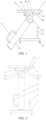
Fig. 1 is a schematic structural diagram of a press cover anti-pinch device of a press cover during rising according to an embodiment of the present application; -
Fig. 2 is a schematic structural diagram of a support of the press cover anti-pinch device in a supporting position according to an embodiment of the present application; -
Fig. 3 is a schematic structural diagram of the press cover anti-pinch device, when a movable end of a reset member comes into contact with an unlocking trigger, according to an embodiment of the present application; -
Fig. 4 is a schematic structural diagram of the press cover anti-pinch device, after the movable end of the reset member come into contact with the unlocking trigger, according to an embodiment of the present application; -
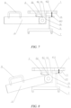
Fig. 5 is a schematic structural diagram of a press cover anti-pinch device of a press cover during rising according to another embodiment of the present application; -
Fig. 6 is a schematic structural diagram of a support of the press cover anti-pinch device in a supporting position according to another embodiment of the present application; -
Fig. 7 is a schematic structural diagram of the press cover anti-pinch device, when a movable end of a reset member comes into contact with an unlocking trigger, according to another embodiment of the present application; -
Fig. 8 is a schematic structural diagram of the press cover anti-pinch device, when the movable end of the reset member comes into contact with the unlocking trigger, according to another embodiment of the present application; -
Fig. 9 is a schematic structural diagram of a press cover anti-pinch device of a press cover during rising according to a further embodiment of the present application; -
Fig. 10 is a schematic structural diagram of a support of the press cover anti-pinch device in a supporting position according to a further embodiment of the present application; -
Fig. 11 is a schematic structural diagram of the press cover anti-pinch device, when a movable end of a reset member comes into contact with an unlocking trigger, according to a further embodiment of the present application; -
Fig. 12 is a schematic structural diagram of the press cover anti-pinch device, when the movable end of the reset member comes into contact with the unlocking trigger, according to a further embodiment of the present application. -
- 1.
- Cover body;
- 11.
- Supporting surface;
- 2.
- Connector;
- 3.
- Support;
- 31.
- Curved surface portion;
- 32.
- Second locking structure;
- 4.
- Locking mechanism;
- 41.
- Reset member; 411. Movable end; 412. Spring;
- 42.
- First locking structure;
- 5.
- Unlocking trigger;
- 6.
- Handle structure;
- 7.
- Base.
- In order to explain the technical contents, structural features and achieved objects and effects of the technical solutions in detail, the following detailed description will be given in conjunction with the specific embodiments and the accompanying drawings.
- Embodiments of the technical solutions of the present application will be described in more detail below with reference to the drawings. The following embodiments are merely intended to more clearly illustrate the technical solutions of the present application, so they merely serve as examples, but are not intended to limit the scope of protection of the present application.
- Unless otherwise defined, all technical and scientific terms used herein have the same meanings as those commonly understood by those skilled in the art to which the present application belongs. The terms used herein are merely for the purpose of describing specific embodiments, but are not intended to limit the present application. The terms "comprising" and "having" and any variations thereof in the description and the claims of the present application as well as the brief description of the accompanying drawings described above are intended to cover non-exclusive inclusion.
- In the description of the embodiments of the present application, the technical terms "first", "second", etc. are merely used for distinguishing different objects, and are not to be construed as indicating or implying relative importance or implicitly indicating the number, particular order or primary-secondary relationship of the technical features modified thereby. In the description of the embodiments of the present application, the phrase "a plurality of" means two or more, unless otherwise explicitly and specifically defined.
- The phrase "embodiment" mentioned herein means that the specific features, structures, or characteristics described in conjunction with the embodiment can be encompassed in at least one embodiment of the present application. The phrase at various locations in the description does not necessarily refer to the same embodiment, or an independent or alternative embodiment exclusive of another embodiment. Those skilled in the art understand explicitly or implicitly that the embodiment described herein may be combined with another embodiment.
- In the description of the embodiments of the present application, the term "and/or" is merely intended to describe the associated relationship of associated objects, indicating that three relationships can exist, for example, A and/or B can include: the three instances of A alone, A and B simultaneously, and B alone. In addition, the character "/" herein generally indicates an "or" relationship between the associated objects.
- In the description of the embodiments of the present application, the term "a plurality of" means two or more (including two), similarly the term "a plurality of groups" means two or more groups (including two groups), and the term "a plurality of pieces" means two or more pieces (including two pieces).
- In the description of the embodiments of the present application, the orientation or position relationship indicated by the technical terms "central", "longitudinal", "transverse", "length", "width", "thickness", "upper", "lower", "front"; "rear", "left", "right", "vertical", "horizontal", "top", "bottom", "inner", "outer", "clockwise", "counterclockwise", "axial", "radial", "circumferential", etc. are based on the orientation or position relationship shown in the drawings and are merely intended to facilitate and simplify the description of the embodiments of the present application, rather than indicating or implying that the device or element considered must have a particular orientation or be constructed and operated in a particular orientation, and therefore not to be construed as limiting the embodiments of the present application.
- In the description of the embodiments of the present application, unless otherwise explicitly specified and defined, the technical terms "mounting", "mutual connection", "connection", "fixing", etc. should be understood in a broad sense, for example, they may be a fixed connection, a detachable connection, or an integrated connection; may be a mechanical connection or an electrical connection; and may be a direct connection or an indirect connection through an intermediate medium, and may be communication between interiors of two elements or interaction between the two elements. For those of ordinary skill in the art, the specific meaning of the above terms in the embodiments of the present application can be understood according to specific situations.
- At present, a press cover apparatus has been widely used in the field of production and processing. The press cover apparatuses has a cover body, which needs to be opened during operation and is closed after an operator finishes the operation. In addition to a manual manner, the cover body of the press cover apparatus may also be opened or closed in an electric-motor-driven, hydraulically-driven, or cylinder-driven manner, etc. However, no matter what manner is used, the cover body is risen to a certain height in an opened state, and the operator needs to extend the hand into a vertical projection area range of the cover body during operation. If the cover body falls down suddenly due to a fault at this time, the hand of the operator will be pinched and hurt, so there is a potential safety hazard.
- In order to improve the safety of the operation, when the cover body of the press cover is in the opened state, the operator often uses one or more support rods to support the cover body, one end of the support rod abutting against a lower surface of the cover body, and the other end thereof abutting against a contact surface. However, the inventors have noted that the support rod will be relatively moved on the contact surface if it is subjected to an external force, and once the support rod is moved, the support rod is very prone to being removed from a supporting state due to the action of gravity of the cover body, and if the operator is operating at this time, the cover body suddenly falling down will directly pinch and hurt the hand of the operator, so there is still a great potential safety hazard in the manner of using only the support rod to support the opened cover body.
- For example, safe production is pursued during manufacturing of lithium batteries, and proportioned powder feeding is the first process of lithium battery manufacturing. Due to the constraints of production techniques and equipment technology, at present, main powder materials are mostly fed in a semi-automatic manner in a factory. When the operator operates a semi-automatic feeding system, it is required to extend under a press cover of a feeder so as to sleeve a discharge port of a jumbo bag into a liner of a delivery port. However, since the press cover is heavy and is usually driven by a cylinder or an electric motor, so there is a risk that the hand of the operator are pinched in the feeding process of the operation.
- In order to solve the problem that the cover body of the press cover suddenly falling down is prone to pinching and hurting the hand of the operator, the inventors, after intensive research, designed a press cover anti-pinch device, so that a
support 3 can have a better stability when supporting the press cover, preventing the cover body suddenly falling down from directly pinching the hand of the operator. - With reference to
Figs. 1 to 12 , the present application provides a press cover anti-pinch device. The press cover anti-pinch device includes aconnector 2 and asupport 3. Theconnector 2 is arranged at a lower side of acover body 1 of a press cover and is fixed to the press cover. Thesupport 3 is hinged to theconnector 2 and is rotatably arranged in a supporting position or in a collapsed position. When thesupport 3 is arranged in the supporting position, thesupport 3 swings down and supports the press cover on a supportingsurface 11, and when thesupport 3 is arranged in the collapsed position, thesupport 3 is collapsed and the press cover is lowered. - The supporting position refers to a position where the
support 3 is located when thesupport 3 plays a supporting role, and is preferably a vertical position perpendicular to the lower surface of thecover body 1 of the press cover, but may also be a position at other angles to the lower surface of thecover body 1 of the press cover. In short, when thesupport 3 is in a position where thesupport 3 can support thecover body 1 of the press cover, the position can be referred to as the supporting position. - The collapsed position is named relative to the supporting position, and when the
support 3 is in the supporting position, thesupport 3 applies a supporting force to the lower surface of thecover body 1 of the press cover, so that thecover body 1 of the press cover cannot fall down. Thus, when it is required to lower the press cover, it is necessary to remove thesupport 3 from the supporting position, and thesupport 3 is rotated, after being removed from the supporting position, to a position allowing thecover body 1 of the press cover to be lowered, which is referred to as the collapsed position. The collapsed position is preferably set horizontally relative to the lower surface of the press cover, but may also be a position at other angles to the lower surface of thecover body 1 of the press cover. In short, when thesupport 3 is rotated, after being removed from the supporting position, to a position where thesupport 3 no longer supports thecover body 1 of the press cover, and thecover body 1 of the press cover can be lowered, the position can be referred to as the collapsed position. - Compared with the prior art, the press cover anti-pinch device provided by the present application includes the
connector 2 and thesupport 3, wherein when thesupport 3 is arranged in the supporting position, thesupport 3 swings down and supports the press cover on the supportingsurface 11, and when thesupport 3 is arranged in the collapsed position, thesupport 3 is collapsed and the press cover is lowered. During use, when the press cover is in the opened state, thesupport 3 swings down and supports the press cover on the supportingsurface 11, so that thesupport 3 provides a supporting force to the press cover, and when the hand of a user perform an operation within a projection area range of the press cover, the press cover cannot fall down even if the press cover is faulty, effectively ensuring the safety of a user during the operation. When the operation is completed, thesupport 3 is arranged in the collapsed position, and at this time, thesupport 3 is collapsed and the press cover is lowered for a next operation. Since thesupport 3 is hinged to theconnector 2 and theconnector 2 is in turn fixed to the lower side of thecover body 1 of the press cover, thesupport 3 cannot relatively move when thesupport 3 is in the supporting position, improving the safety of the operation. - According to some embodiments of the present application, optionally, the press cover anti-pinch device further includes a
locking mechanism 4. Thelocking mechanism 4 is arrangeable in a locking position or in an unlocking position, wherein when thelocking mechanism 4 is arranged in the locking position, thesupport 3 is locked in the supporting position and/or the collapsed position, and when thelocking mechanism 4 is arranged in the unlocking position, thesupport 3 is rotatable to another position other than the locking position. Providing thelocking mechanism 4 enables thesupport 3 to be in a locked state when located in the supporting position and/or the collapsed position, avoiding relative sliding and further improving the safety of the operation. - The locking position, as the name implies, refers to a position in the locked state, and when the
locking mechanism 4 is in the locking position, thesupport 3 is locked in the supporting position and/or the collapsed position, so as to avoid the relative movement of thesupport 3 in the supporting position and/or the collapsed position, further improving the stability of thesupport 3. - The unlocking position, as the name implies, refers to a position in an unlocked state, and when the
locking mechanism 4 is in the unlocking position, thesupport 3 is in a rotatable state and can be rotated to another position other than the locking position. - When the
support 3 is in the supporting position, thelocking mechanism 4 is in the unlocking position; and when thesupport 3 is in the collapsed position, thelocking mechanism 4 is in the locking position. After the operation is finished, the operator can rotate thesupport 3 from the supporting position to the collapsed position so as to lower the press cover. - In some other embodiments, the relationship between the
support 3 and thelocking mechanism 4 may also be set such that when thesupport 3 is in the supporting position, thelocking mechanism 4 is in the locking position; and when thesupport 3 is in the collapsed position, thelocking mechanism 4 is in the unlocking position. In the embodiment, since thesupport 3 is locked by thelocking mechanism 4 when located in the supporting position, the relative sliding of thesupport 3 can be avoided, effectively improving the stability of thesupport 3 in the supporting position. After the operation is finished, the operator can first switch thelocking mechanism 4 from the locking position to the unlocking position by adjusting the locking mechanism so that thesupport 3 is in the rotatable state, and the operator then rotates thesupport 3 from the supporting position to the collapsed position so as to lower the press cover to complete the operation. - In some other embodiments, the relationship between the
support 3 and thelocking mechanism 4 may also be set such that when thesupport 3 is in the supporting position, thelocking mechanism 4 is in the locking position; and when thesupport 3 is in the collapsed position, thelocking mechanism 4 is in the locking position. In the embodiment, since thesupport 3 is locked by the locking mechanism in both the supporting position and the collapsed position, the relative sliding of thesupport 3 in the supporting position and the collapsed position can be avoided, further improving the safety of the operation. When the operator finishes the operation, if thesupport 3 is in the supporting position at this time, the operator can first switch the locking mechanism from the locking position to the unlocking position by adjusting the locking mechanism so that thesupport 3 is in the rotatable state, the operator then rotates thesupport 3 from the supporting position to the collapsed position, and when thesupport 3 is in the collapsed position, thesupport 3 is locked again by the locking mechanism, so as to ensure that thesupport 3 cannot relatively move in the lowering process of the press cover, thus improving the safety of the operation. Preferably, after the press cover is lowered to a predetermined height, namely, after thecover body 1 of the press cover is closed to complete this operation, the locking mechanism is switched from the locking position to the unlocking position again so that thesupport 3 is in the rotatable state, so as to ensure normal use during the next operation. - In some embodiments, the
locking mechanism 4 includes: areset member 41. Thereset member 41 is configured to automatically reset the locking mechanism from the unlocking position to the locking position when thesupport 3 is arranged in the supporting position and/or the collapsed position . Providing thereset member 41 enables the locking mechanism to be automatically reset from the unlocking position to the locking position when thesupport 3 is rotated to the supporting position and/or the collapsed position, so that the operation is more convenient and faster. - Preferably, the
reset member 41 is a gravitational reset member or an elastic reset member. The gravitational reset member automatically resets the locking mechanism from the unlocking position to the locking position by means of a downward movement due to its own gravity; and the elastic reset member automatically resets the locking mechanism from the unlocking position to the locking position by means of the action of an elastic potential energy. Configuring the reset member as the gravitational reset member or the elastic reset member can better meet the requirements of different application scenarios. For example, thereset member 41 inFigs. 1-4 is the gravitational reset member, thereset member 41 inFigs. 9-12 is the elastic reset member, and thereset member 41 inFigs. 5-8 is a combination of the gravitational reset member and the elastic reset member. The specific operating principles of the three forms will be described in detail below. - In some embodiments, the
reset member 41 is hinged to theconnector 2 or thesupport 3, and swings down by means of its own gravity to automatically reset the locking mechanism to the locking position. When thesupport 3 is rotatable, the locking mechanism is in the unlocking position, and thereset member 41 is risen up under the pressure of thesupport 3; and when thesupport 3 is rotated to the supporting position and/or the collapsed position, thereset member 41 swings down by means of its own gravity to automatically reset the locking mechanism to the locking position so as to ensure that the locking mechanism locks thesupport 3 in the supporting position and/or the collapsed position. Providing thereset member 41 hinged to theconnector 2 or thesupport 3 enables switching between the locking position and the unlocking position of the locking mechanism to be more convenient and faster. - As shown in
Figs. 1-8 , thereset member 41 may be a cross rod structure, and as shown inFigs. 9-12 , thereset member 41 may also be a cross rod structure. In some other embodiments, thereset member 41 may also be an L-shaped structure. The L-shaped structure includes a cross rod and a vertical rod, wherein afirst locking structure 42 is arranged on the cross rod to fit with asecond locking structure 32 on thesupport 3, thereby switching the locking mechanism between the locking position and the unlocking position, and aspring 412 connected to thesupport 3 is arranged on the vertical rod to automatically reset the locking mechanism to the locking position. Of course, thereset member 41 may also be of structures in other shapes, in short, any structure of thereset member 41 enabling the locking mechanism to be automatically reset to the locking position falls within the scope of protection of the embodiment. - In some embodiments, the press cover anti-pinch device further includes an unlocking
trigger 5. The unlockingtrigger 5 is arranged in a contact position and is configured to unlock the locking mechanism from the locking position to the unlocking position when thereset member 41 comes into contact with the unlockingtrigger 5. When it is required to switch thesupport 3 from the locked state to the rotatable state, it is only necessary to make thereset member 41 come into contact with the unlockingtrigger 5, so that thereset member 41 unlocks the locking mechanism from the locking position to the unlocking position by means of a reset action, and at this time, thesupport 3 is switched from the locked state to the rotatable state. Providing the unlockingtrigger 5 enables switching between the locking position and the unlocking position of the locking mechanism to be more convenient and faster, and thus switching from the locked state to the rotatable state of thesupport 3 to be more convenient and faster. - The unlocking
trigger 5 may be a trigger rod, a trigger block, etc., the unlockingtrigger 5 may be arranged transversely or longitudinally, and the unlockingtrigger 5 only needs to be capable of coming into contact with thereset member 41 and to be capable of unlocking the locking mechanism from the locking position to the unlocking position after the two comes into contact with each other. Any structure capable of meeting the functional requirement falls within the scope of protection of the embodiment. As shown inFigs. 1-12 , the unlockingtrigger 5 is arranged longitudinally on abase 7. - In some embodiments, the contact position is a position where the
reset member 41 comes into contact with the unlocking trigger when the press cover is lowered. In this way, when the press cover is lowered, thereset member 41 comes into contact with the unlockingtrigger 5 in the contact position, so that the locking mechanism is unlocked from the locking position to the unlocking position under the action of thereset member 41, and at this time, thesupport 3 is switched from the locked state to the rotatable state, thereby ensuring that when the press cover is risen, thesupport 3 can swing down and support the press cover on the supportingsurface 11 during the next operation. Setting the contact position as the position where thereset member 41 comes into contact with the unlocking trigger when the press cover is lowered can ensure that thesupport 3 is automatically switched to the rotatable state when the press cover is lowered, so that the operation is more convenient during next use. - In some embodiments, the
locking mechanism 4 includes thefirst locking structure 42 and thesecond locking structure 32, wherein thefirst locking structure 42 is arranged on or connected to theconnector 2 and has a first engagement portion, thesecond locking structure 32 is arranged on or connected to thesupport 3 and has a second engagement portion adapted to the first engagement portion, and when thesupport 3 is arranged in the supporting position and/or the collapsed position, the first engagement portion is engaged with the second engagement portion. The engagement between thefirst locking structure 42 and thesecond locking structure 32 to lock thesupport 3 in the supporting position and/or the collapsed position can prevent thesupport 3 from moving in the supporting position and/or the collapsed position, improving the safety of the operation. When the first engagement portion and the second engagement portion are separated from each other, namely, when the locking mechanism is in the unlocking position, thesupport 3 is in the rotatable state again, and state switching is convenient and free. - In short, as part of the
locking mechanism 4, thefirst locking structure 42 may be arranged directly on thelocking mechanism 4 and integrally formed with other components of thelocking mechanism 4; or the first locking structure may be first arranged on a further component and is then connected to theconnector 2 or thesupport 3 by means of the further component. For example, thefirst locking structure 42 is first arranged on a connecting rod and is then connected to theconnector 2 or thesupport 3 by means of the connecting rod. - The engagement connection manner of the first engagement portion and the second engagement portion includes: various concave-convex fit structures such as a key and key groove fit connection, a protrusion and recess fit connection, and a two-boss fit structure (such as the fitting of a protrusion or a snap key, etc.). Any structure capable of achieving the engagement between the first engagement portion and the second engagement portion fall within the scope of protection of the embodiment.
- In some embodiments, the
connector 2 or thesupport 3 has acurved surface portion 31 with a hinged shaft as a central axis at the end where theconnector 2 is hinged to thesupport 3, and the first engagement portion or the second engagement portion is arranged on thecurved surface portion 31. In this way, when thesupport 3 is rotated to the supporting position and/or the collapsed position, the first engagement portion and the second engagement portion are automatically engaged closely, so that locking of thesupport 3 is more convenient and faster. - The
curved surface portion 31 may be in a shape of a variety of curved surfaces, such as a circular cylindrical surface, an elliptic cylindrical surface, or a parabolic surface. Preferably, thecurved surface portion 31 may be in the shape of the circular cylindrical surface. In this way, during rotation, thesupport 3 can drive thecurved surface portion 31 with the hinged shaft as the central axis, and thus the second engagement portion arranged on thecurved surface portion 31, to move. When thesupport 3 is rotated to the supporting position and/or the collapsed position, the first engagement portion and the second engagement portion are automatically engaged closely, so that locking of thesupport 3 is more convenient and faster. - In some embodiments, the
locking mechanism 4 further includes: thereset member 41. Thereset member 41 is hinged to theconnector 2 or thesupport 3 and is configured to automatically reset thelocking mechanism 4 from the unlocking position to the locking position when thesupport 3 is arranged in the supporting position and/or the collapsed position, and thereset member 41 has thefirst locking structure 42 or thesecond locking structure 32. Thefirst locking structure 42 or thesecond locking structure 32 is arranged on thereset member 41, such that when thesupport 3 is in the supporting position and/or the collapsed position, thesupport 3 is locked by means of the engagement between the locking structure on thereset member 41 and the locking structure on thesupport 3; and when the locking structure on thereset member 41 is separated from the locking structure on thesupport 3, thesupport 3 is in the rotatable state again, so that the two states of thesupport 3 are free to switch, and the operation is more convenient and faster. - In some embodiments, one end of the
reset member 41 is hinged to theconnector 2, the other end thereof is amovable end 411, thefirst locking structure 42 is arranged on thereset member 41, and the first engagement portion is arranged between the hinged end and themovable end 411 of theconnector 2; and the unlocking position of the unlockingtrigger 5 is arranged in a path along which themovable end 411 of thereset member 41 is lowered with the press cover. Since the unlocking position of the unlockingtrigger 5 is arranged in the path along which themovable end 411 of thereset member 41 is lowered with the press cover, when the press cover is lowered, themovable end 411 is driven to lower therewith, and when themovable end 411 is lowered to the unlocking position of the unlockingtrigger 5, the unlockingtrigger 5 applies an upward reaction force to themovable end 411 of thereset member 41, so that the first engagement portion and the second engagement portion are separated from each other to ensure that thesupport 3 is in the rotatable state when being collapsed for next use. - Preferably, the
reset member 41 is arranged transversely. Thereset member 41 is arranged transversely, so that it can be ensured that themovable end 411 of the reset member can easily come into contact with the unlockingtrigger 5 during the lowering of thereset member 41 with the press cover. - In some embodiments, when the
connector 2 is risen with thecover body 1, thesupport 3 swings down to the supporting position by means of its own gravity. Since theconnector 2 is arranged at the lower side of thecover body 1 of the press cover and thesupport 3 is in turn hinged to theconnector 2, during rising, thecover body 1 of the press cover drives theconnector 2 to rise, and due to the action of gravity, thesupport 3 swings down to the supporting position, so as to support thecover body 1 of the press cover. With such an arrangement, it can be ensured that when thecover body 1 is risen to a certain height, thesupport 3 automatically swings down to the supporting position for providing a support function to thecover body 1, further improving the safety of production operation. - In some embodiments, a
handle structure 6 for the operator to apply a force is arranged on thesupport 3. After use, the operator can apply an acting force to thesupport 3 in a rotation direction by means of thehandle structure 6, so that thesupport 3 is removed from the supporting position, the press cover is then lowered, and thesupport 3 is collapsed for next use. - Reference is mad to
Figs. 1-4 , which are schematic operation diagrams of a press cover anti-pinch device according to an embodiment of the present application. In the embodiment, thereset member 41 is a gravitational reset member. The first engagement portion is a protrusion, and the second engagement portion is a recess. The first engagement portion is arranged on thereset member 41, and the second engagement portion is arranged on thesupport 3 and is located on thecurved surface portion 31 with the hinged shaft as the central axis at the end of the support hinged to theconnector 2. The operating principle of the press cover anti-pinch device inFigs. 1-4 will be described below. - Reference is made to
Fig. 1 , which is a schematic structural diagram of a press cover anti-pinch device of a press cover during rising according to an embodiment of the present application. After the press cover is opened, the press cover is driven by a driving mechanism thereof to slowly rise, so that theconnector 2 arranged on the lower surface of thecover body 1 of the press cover is risen as thecover body 1 is risen, and thesupport 3 swings down to the supporting position due to its own gravity. For example, inFig. 1 , when thecover body 1 of the press cover is risen upward, thesupport 3 swings in a counterclockwise direction under the action of its own gravity. - Reference is made to
Fig. 2 , which is a schematic structural diagram of thesupport 3 of the press cover anti-pinch device in the supporting position according to an embodiment of the present application. When thesupport 3 swings down to the lowest supporting position, which is perpendicular to the lower surface of thepress cover body 1, the operator can perform an operation, for example, a feeding or taking operation performed within the area range of thecover body 1. During the operation, due to the support of thesupport 3, thecover body 1 does not fall down even if the cover body is faulty at this time, and the safety of the operator during the operation is effectively ensured. - Reference is made to
Fig. 3 , which is a schematic structural diagram of the press cover anti-pinch device, when themovable end 411 of thereset member 41 comes into contact with the unlockingtrigger 5, according to an embodiment of the present application. After the operation is finished, the operator can apply an acting force to thesupport 3 from the supporting position to the collapsed position by means of a handle on thesupport 3, so that thesupport 3 is rotated from the supporting position to the collapsed position. When thesupport 3 is in the collapsed position, thereset member 41 moves downwards due to the action of gravity, so that the first engagement portion on thefirst locking structure 42 is just engaged with the second engagement portion on thesecond locking structure 32, and at this time, the locking mechanism is in the locking position and no relative sliding occurs between thesupport 3 and theconnector 2, ensuring the safety during the falling of the press cover. For example, inFig. 3 , when thesupport 3 is in the collapsed position, thesupport 3 is arranged transversely. The press cover is then controlled to lower, so that when the press cover is lowered to the position shown inFig. 3 , themovable end 411 of thereset member 41 just comes into contact with the unlockingtrigger 5 arranged below themovable end 411. - Reference is made to
Fig. 4 , which is a schematic structural diagram of the press cover anti-pinch device, after themovable end 411 of thereset member 41 comes into contact with the unlockingtrigger 5, according to an embodiment of the present application. When themovable end 411 of thereset member 41 is lowered to the unlocking position of the unlockingtrigger 5, the unlockingtrigger 5 applies an upward reaction force to themovable end 411 of thereset member 41, so that the first engagement portion on thefirst locking structure 42 is separated from the second engagement portion on thesecond locking structure 32 to ensure that thesupport 3 is in the rotatable state when being collapsed for next use. - Reference is made to
Figs. 5-8 , which are schematic operation diagrams of a press cover anti-pinch device according to another embodiment of the present application. The difference from the embodiment inFigs. 1-4 lies in that, the press cover anti-pinch device is provided with aspring 412 between themovable end 411 of thereset member 41 and the lower surface of thepress cover body 1, wherein thespring 412 is in a compressed state when thesupport 3 is in the supporting position. In the embodiment, thereset member 41 is a combination of a gravitational reset member and an elastic reset member. The first engagement portion is a protrusion, and the second engagement portion is a recess. The first engagement portion is arranged on thereset member 41, and the second engagement portion is arranged on thesupport 3 and is located on thecurved surface portion 31 with the hinged shaft as the central axis at the end of the support hinged to theconnector 2. The operating principle of the press cover anti-pinch device inFigs. 5-8 will be described below. - Reference is made to
Fig. 5 , which is a schematic structural diagram of a press cover anti-pinch device of a press cover during rising according to an embodiment of the present application. After the press cover is opened, the press cover is driven by a driving mechanism thereof to slowly rise, so that theconnector 2 arranged on the lower surface of thecover body 1 of the press cover is risen as thecover body 1 is risen, and thesupport 3 swings down to the supporting position due to its own gravity. For example, inFig. 5 , when thecover body 1 of the press cover is risen upward, thesupport 3 swings in the counterclockwise direction under the action of its own gravity. Since thecurved surface portion 31 with the hinged shaft as the central axis at the end of thesupport 3 hinged to theconnector 2 applies an upward acting force to the protrusion of thefirst locking structure 42, so that themovable end 411 of thereset member 41 is moved upward to compress thespring 412, and at this time, thespring 412 arranged between themovable end 411 of thereset member 41 and the lower surface of thepress cover body 1 is thus in the compressed state. - Referring to
Fig. 6 , when thesupport 3 swings down to the lowest supporting position, which is perpendicular to the lower surface of thepress cover body 1, themovable end 411 of thereset member 41 always applies a compression force to thespring 412. The operator can perform an operation within the area range of the press cover, for example, a feeding or taking operation performed within the area range of thecover body 1. During the operation, due to the support of thesupport 3, thecover body 1 does not fall down even if the cover body is faulty at this time, and the safety of the operator during the operation is effectively ensured. - Referring to
Fig. 7 , after the operation is finished, the operator can apply an acting force to thesupport 3 from the supporting position to the collapsed position by means of a handle on thesupport 3, so that thesupport 3 is rotated from the supporting position to the collapsed position. When the first engagement portion on thefirst locking structure 42 is positioned corresponding to the second engagement portion on thesecond locking structure 32, due to the action of a restoring force of thespring 412, a downward elastic force is applied to themovable end 411 of thereset member 41, so that the first engagement portion is engaged with the second engagement portion, and at this time, the locking mechanism is in the locking position and thesupport 3 is in the collapsed position. No relative sliding occurs between thesupport 3 and theconnector 2 due to the engagement between the first engagement portion and the second engagement portion, and the safety is ensured during the falling of the press cover. The press cover is then controlled to lower, so that when the press cover is lowered to the position shown inFig. 7 , themovable end 411 of thereset member 41 just comes into contact with the unlockingtrigger 5 arranged below themovable end 411. - Referring to
Fig. 8 , when themovable end 411 of thereset member 41 is lowered to the unlocking position of the unlockingtrigger 5, the unlockingtrigger 5 applies an upward reaction force to themovable end 411 of thereset member 41, so that the first engagement portion on thefirst locking structure 42 is separated from the second engagement portion on thesecond locking structure 32 to ensure that thesupport 3 is in the rotatable state when being collapsed for next use. - Reference is made to
Figs. 9-12 , which are schematic operation diagrams of a press cover anti-pinch device according to a further embodiment of the present application. The differences from the embodiments inFigs. 1-8 lie in that, thereset member 41 is an elastic reset member, and the elastic reset member includes a vertical rod, a snap block and aspring 412, wherein the vertical rod is longitudinally arranged and is connected to the lower surface of thepress cover body 1, thespring 412 is arranged between the snap block and the vertical rod, and the first engagement portion is arranged on the snap block. The side wall of theconnector 2 adjacent to the snap block is provided with a notch enabling the first engagement portion to enter. When the first engagement portion is positioned opposite the second engagement portion , the first engagement portion enters the notch and is engaged with the second engagement portion; and when the first engagement portion is not positioned opposite the second engagement portion, the first engagement portion abuts against thecurved surface portion 31 with the hinged shaft as the central axis at the end of thesupport 3 hinged to theconnector 2, and at this time, thespring 412 between the snap block and the vertical rod is in the compressed state. The first engagement portion is a protrusion, and the second engagement portion is a recess. The operating principle of the press cover anti-pinch device inFigs. 9-12 will be described below. - Referring to
Fig. 9 , after the press cover is opened, the press cover is driven by a driving mechanism thereof to slowly rise, so that theconnector 2 arranged on the lower surface of thecover body 1 of the press cover is risen as thecover body 1 is risen, and thesupport 3 swings down to the supporting position due to its own gravity. For example, inFig. 9 , when thecover body 1 of the press cover is risen upward, thesupport 3 swings in the counterclockwise direction under the action of its own gravity. Since, during the rotation of thesupport 3 from an initial position to the supporting position, the position on thecurved surface portion 31 in contact with a protrusion on the snap block is always not the position of the recess, thespring 412 on thereset member 41 and arranged between the vertical rod and the snap block is always in the compressed state. - Referring to
Fig. 10 , when thesupport 3 swings down to the lowest supporting position, which is perpendicular to the lower surface of thepress cover body 1, themovable end 411 of thereset member 41 still applies a compression force to thespring 412. The operator can perform an operation within the area range of the press cover, for example, a feeding or taking operation performed within the area range of thecover body 1. During the operation, due to the support of thesupport 3, thecover body 1 does not fall down even if the cover body is faulty at this time, and the safety of the operator during the operation is effectively ensured. - Referring to
Fig. 11 , after the operation is finished, the operator can apply an acting force to thesupport 3 from the supporting position to the collapsed position by means of a handle on thesupport 3, so that thesupport 3 is rotated from the supporting position to the collapsed position. When thesupport 3 is rotated to the collapsed position, the recess of thecurved surface portion 31 is just aligned with the protrusion of the snap block, and at this time, due to the action of the restoring force of the spring, a leftward elastic force is applied to the snap block, so that the protrusion on the snap block extends into the recess of thecurved surface portion 31 by means of the notch in theconnector 2. At this time, the locking mechanism is in the locking position, and thesupport 3 is in a locked state. Due to the engagement between the recess and the protrusion, thesupport 3 cannot relatively slide when the press cover falls down, and the safety is ensured during the falling of the press cover. The press cover can then be controlled to lower, so that when the press cover ls lowered to the position shown inFig. 11 , a lower end face of the snap block of thereset member 41 just comes into contact with an upper end face of the unlockingtrigger 5. Preferably, the lower end face of the snap block and the upper end face of the unlockingtrigger 5 are configured as inclined surfaces shaped to adapt to each other. - Referring to
Fig. 12 , after the lower end face of the snap block of thereset member 41 comes into contact with the upper end face of the unlockingtrigger 5, the snap block serves as a sliding end of thereset member 41, the unlockingtrigger 5 applies an upward reaction force to the snap block, so that the recess on thecurved surface portion 31 of thesupport 3 is separated from the protrusion on the snap block, namely, the locking mechanism is switched from the locking position to the unlocking position again, so as to ensure that thesupport 3 is in the rotatable state when being collapsed for next use. - In a second aspect, the inventors further provide an apparatus having a press cover, the press cover being openable or closable, and a press cover anti-pinch device as described in the first aspect being arranged at a lower side of the press cover.
- Compared with the prior art, the apparatus having the press cover in the present application includes the press cover and the press cover anti-pinch device, the
support 3 in the press cover anti-pinch device can be in the supporting position after the press cover is risen to support thecover body 1 of the press cover, preventing thecover body 1 from suddenly falling down to hurt an operator due to a fault, and effectively ensuring the safety of the operator during operation. - In some embodiments, the apparatus is a tank-type apparatus. The tank-type apparatus is often used in daily production and processing. Arranging the press cover anti-pinch device in the tank-type apparatus can cover more operation scenarios as much as possible to ensure the safety of an operator during operation. The tank-type apparatus may be a storage tank, a reaction tank, a stirring tank, etc. and any tank-type apparatus having a press cover falls within the scope of protection of the embodiment.
- Finally, it should be noted that the above embodiments are merely used for illustrating rather than limiting the technical solution of the present application. Although the present application has been illustrated in detail with reference to the foregoing embodiments, it should be understood by those of ordinary skill in the art that the technical solutions recorded in the foregoing embodiments may still be modified, or some or all of the technical features thereof may be equivalently substituted; and such modifications or substitutions do not make the essence of the corresponding technical solution depart from the scope of the technical solutions of the embodiments of the present application, and should fall within the scope of the claims and the description of the present application. In particular, the technical features mentioned in the embodiments can be combined in any manner, provided that there is no structural conflict. The present application is not limited to the specific embodiments disclosed herein but includes all the technical solutions that fall within the scope of the claims.
Claims (14)
- A press cover anti-pinch device, comprising:a connector (2) arranged at a lower side of a cover body (1) of a press cover and fixed to the press cover; anda support (3) hinged to the connector (2) and rotatably arranged in a supporting position or in a collapsed position, wherein when the support (3) is arranged in the supporting position, the support (3) swings down and supports the press cover on a supporting surface (11), and when the support (3) is arranged in the collapsed position, the support (3) is collapsed and the press cover is lowered; characterized in thatthe press cover anti-pinch device further comprises:
a locking mechanism (4) arrangeable in a locking position or in an unlocking position, wherein when the locking mechanism (4) is arranged in the locking position, the support (3) is locked in the supporting position and/or the collapsed position, and when the locking mechanism (4) is arranged in the unlocking position, the support (3) is rotatable to another position other than the locking position. - The press cover anti-pinch device according to claim 1, wherein the locking mechanism (4) comprises:
a reset member (41) configured to automatically reset the locking mechanism (4) from the unlocking position to the locking position when the support (3) is arranged in the supporting position and/or the collapsed position. - The press cover anti-pinch device according to claim 2, wherein the reset member (41) is a gravitational reset member or an elastic reset member.
- The press cover anti-pinch device according to claim 3, wherein the reset member (41) is hinged to the connector (2) or the support (3), and swings down by means of its own gravity to automatically reset the locking mechanism (4) to the locking position.
- The press cover anti-pinch device according to any one of claims 2 to 4, further comprising:
an unlocking trigger (5) arranged in a contact position and configured to unlock the locking mechanism (4) from the locking position to the unlocking position when the reset member (41) comes into contact with the unlocking trigger (5). - The press cover anti-pinch device according to claim 5, wherein the contact position is a position where the reset member (41) comes into contact with the unlocking trigger (5) when the press cover is lowered.
- The press cover anti-pinch device according to any one of claims 1 to 6, wherein the locking mechanism (4) comprises:a first locking structure (42) arranged on or connected to the connector (2) and having a first engagement portion; anda second locking structure (32) arranged on or connected to the support (3) and having a second engagement portion adapted to the first engagement portion, wherein when the support (3) is arranged in the supporting position and/or the collapsed position, the first engagement portion is engaged with the second engagement portion.
- The press cover anti-pinch device according to claim 7, wherein the connector (2) or the support (3) has a curved surface portion (31) with a hinged shaft as a central axis at the end where the connector (2) is hinged to the support (3), and the first engagement portion or the second engagement portion is arranged on the curved surface portion (31).
- The press cover anti-pinch device according to claim 7 or 8, wherein the locking mechanism (4) further comprises:
a reset member (41) hinged to the connector (2) or the support (3) and configured to automatically reset the locking mechanism (4) from the unlocking position to the locking position when the support (3) is arranged in the supporting position and/or the collapsed position, the reset member (41) having the first locking structure (42) or the second locking structure (32). - The press cover anti-pinch device according to claim 9, wherein one end of the reset member (41) is hinged to the connector (2), the other end thereof is a movable end (411), the first locking structure (42) is arranged on the reset member (41), and the first engagement portion is arranged between the hinged end and the movable end (411) of the connector (2); and
the unlocking position of the unlocking trigger (5) is arranged in a path along which the movable end (411) of the reset member (41) is lowered with the press cover. - The press cover anti-pinch device according to claim 10, wherein the reset member (41) is arranged transversely.
- The press cover anti-pinch device according to any one of claims 2 to 11, wherein when the connector (2) is risen with the cover body (1), the support (3) swings down to the supporting position by means of its own gravity.
- The press cover anti-pinch device according to any one of claims 2 to 12, wherein a handle structure (6) for an operator to apply a force is arranged on the support (3).
- An apparatus having a press cover, wherein the press cover is openable or closable, and a press cover anti-pinch device according to any one of claims 2 to 13 is arranged at a lower side of the press cover, preferably wherein the apparatus is a tank-type apparatus.
Applications Claiming Priority (2)
| Application Number | Priority Date | Filing Date | Title |
|---|---|---|---|
| CN202122377586.1U CN216003895U (en) | 2021-09-29 | 2021-09-29 | A gland anti-pinch device and equipment with a gland |
| PCT/CN2022/101783 WO2023050934A1 (en) | 2021-09-29 | 2022-06-28 | Gland anti-pinch device and apparatus having gland |
Publications (3)
| Publication Number | Publication Date |
|---|---|
| EP4238886A1 EP4238886A1 (en) | 2023-09-06 |
| EP4238886A4 EP4238886A4 (en) | 2024-05-01 |
| EP4238886B1 true EP4238886B1 (en) | 2025-02-26 |
Family
ID=80523138
Family Applications (1)
| Application Number | Title | Priority Date | Filing Date |
|---|---|---|---|
| EP22874331.6A Active EP4238886B1 (en) | 2021-09-29 | 2022-06-28 | Gland anti-pinch device and apparatus having gland |
Country Status (4)
| Country | Link |
|---|---|
| US (1) | US20230272878A1 (en) |
| EP (1) | EP4238886B1 (en) |
| CN (1) | CN216003895U (en) |
| WO (1) | WO2023050934A1 (en) |
Families Citing this family (1)
| Publication number | Priority date | Publication date | Assignee | Title |
|---|---|---|---|---|
| CN216003895U (en) * | 2021-09-29 | 2022-03-11 | 宁德时代新能源科技股份有限公司 | A gland anti-pinch device and equipment with a gland |
Family Cites Families (18)
| Publication number | Priority date | Publication date | Assignee | Title |
|---|---|---|---|---|
| JPH076207B2 (en) * | 1988-12-27 | 1995-01-30 | 長島鋳物株式会社 | Lid standing device for underground structures |
| DE3907334A1 (en) * | 1989-03-08 | 1990-09-20 | Schleicher Co Feinwerktech | LOCKING DEVICE FOR THE DOOR OF A BALE PRESS |
| FR2674879B1 (en) * | 1991-04-05 | 1995-08-04 | Sodif Sa | SECURITY DEVICE FOR ARTICULATED PAVEMENT OF LOOKING ROAD. |
| DE4344412A1 (en) * | 1993-12-24 | 1995-06-29 | Hess Sb Automatenbau Gmbh | Safety device for industrial shoe-sole press |
| JP3271450B2 (en) * | 1994-12-22 | 2002-04-02 | 村田機械株式会社 | Cover lock mechanism |
| JP2919468B1 (en) * | 1998-07-03 | 1999-07-12 | 長島鋳物株式会社 | Lid receiving frame with fall prevention member |
| DE10234316B4 (en) * | 2002-07-26 | 2004-09-23 | Atika Gmbh & Co. Kg | Mixing device with an electric drive motor and safety device |
| DE102004038488B4 (en) * | 2004-08-07 | 2006-06-14 | Euchner Gmbh + Co. Kg | Monitoring system for controlling access to such as a machine uses a switch that is coupled to an actuator on the door |
| CN203601830U (en) * | 2013-11-15 | 2014-05-21 | 芜湖中集瑞江汽车有限公司 | Manhole cover supporting device |
| CN205402530U (en) * | 2016-02-29 | 2016-07-27 | 国家电网公司 | New forms of energy sewer well lid |
| CN107310689A (en) * | 2017-06-23 | 2017-11-03 | 杨莉 | A kind of manhole cover supporting structure |
| ES2932051T3 (en) * | 2017-10-18 | 2023-01-09 | Euchner Gmbh Co Kg | Security switch |
| CN208429198U (en) * | 2018-05-10 | 2019-01-25 | 纳恩博(北京)科技有限公司 | Support construction and balance car |
| FR3096377B1 (en) * | 2019-05-24 | 2021-04-30 | Fond De Brousseval & Montreuil | IMPROVED SAFETY ROAD SYSTEM |
| US11959320B2 (en) * | 2020-07-08 | 2024-04-16 | Te Connectivity Solutions Gmbh | Latch mechanism for a guard assembly of a processing machine |
| CN112843616B (en) * | 2021-01-27 | 2021-11-16 | 杭州职业技术学院 | Multifunctional hip-opening assisting device and using method thereof |
| CN216003895U (en) * | 2021-09-29 | 2022-03-11 | 宁德时代新能源科技股份有限公司 | A gland anti-pinch device and equipment with a gland |
| JP2026004957A (en) * | 2024-06-26 | 2026-01-15 | セイコーエプソン株式会社 | Cartridge and liquid supply system |
-
2021
- 2021-09-29 CN CN202122377586.1U patent/CN216003895U/en active Active
-
2022
- 2022-06-28 WO PCT/CN2022/101783 patent/WO2023050934A1/en not_active Ceased
- 2022-06-28 EP EP22874331.6A patent/EP4238886B1/en active Active
-
2023
- 2023-05-08 US US18/313,437 patent/US20230272878A1/en active Pending
Also Published As
| Publication number | Publication date |
|---|---|
| EP4238886A1 (en) | 2023-09-06 |
| EP4238886A4 (en) | 2024-05-01 |
| WO2023050934A1 (en) | 2023-04-06 |
| CN216003895U (en) | 2022-03-11 |
| US20230272878A1 (en) | 2023-08-31 |
Similar Documents
| Publication | Publication Date | Title |
|---|---|---|
| JP7736767B2 (en) | Adapters and Rail Sockets | |
| EP3016223B1 (en) | Cradle with a door interlock device for a withdrawable vacuum circuit breaker | |
| CN102168351B (en) | Door lock device | |
| US20230272878A1 (en) | Press cover anti-pinch device and apparatus having press cover | |
| CN112869466B (en) | A folding bed | |
| CN113594813B (en) | Adapter and track socket | |
| CN210396411U (en) | Lock core and unlocking key | |
| CN108105544B (en) | Retractable self-locking flat plate bracket | |
| CN218385048U (en) | Pull-out locking structure of circuit breaker and plug-in circuit breaker | |
| CN115733015B (en) | Adapter and track socket | |
| CN117317742A (en) | Adapters and track sockets | |
| CN218158930U (en) | Case assembly and server | |
| CN220550983U (en) | An opening and closing mechanism for a storage bag lock | |
| CN214414537U (en) | Folding bed | |
| CN112502543B (en) | Electromechanical frequency conversion electromagnetic lock operation method and electromechanical frequency conversion electromagnetic lock | |
| CN217239653U (en) | Battery fixing mechanism and electric vehicle | |
| WO2024008170A1 (en) | Pulling and locking structure of circuit breaker and plug-in circuit breaker | |
| CN212744672U (en) | Blind plate lock | |
| CN109713538A (en) | Power supply adapter | |
| CN111946197B (en) | Intelligent safe with double-section type cabinet door design | |
| CN210396407U (en) | Lock core and unlocking key | |
| CN209942441U (en) | Safety interlock | |
| CN219329626U (en) | Charging cabinet | |
| CN212201642U (en) | Lock core and lock | |
| CN218676991U (en) | Plug-in circuit breaker |
Legal Events
| Date | Code | Title | Description |
|---|---|---|---|
| STAA | Information on the status of an ep patent application or granted ep patent |
Free format text: STATUS: THE INTERNATIONAL PUBLICATION HAS BEEN MADE |
|
| PUAI | Public reference made under article 153(3) epc to a published international application that has entered the european phase |
Free format text: ORIGINAL CODE: 0009012 |
|
| STAA | Information on the status of an ep patent application or granted ep patent |
Free format text: STATUS: REQUEST FOR EXAMINATION WAS MADE |
|
| 17P | Request for examination filed |
Effective date: 20230602 |
|
| AK | Designated contracting states |
Kind code of ref document: A1 Designated state(s): AL AT BE BG CH CY CZ DE DK EE ES FI FR GB GR HR HU IE IS IT LI LT LU LV MC MK MT NL NO PL PT RO RS SE SI SK SM TR |
|
| A4 | Supplementary search report drawn up and despatched |
Effective date: 20240405 |
|
| RIC1 | Information provided on ipc code assigned before grant |
Ipc: F16B 9/00 20060101ALI20240328BHEP Ipc: B65D 90/00 20060101ALI20240328BHEP Ipc: B65D 43/24 20060101AFI20240328BHEP |
|
| RAP1 | Party data changed (applicant data changed or rights of an application transferred) |
Owner name: CONTEMPORARY AMPEREX TECHNOLOGY(HONG KONG) LIMITED |
|
| GRAP | Despatch of communication of intention to grant a patent |
Free format text: ORIGINAL CODE: EPIDOSNIGR1 |
|
| STAA | Information on the status of an ep patent application or granted ep patent |
Free format text: STATUS: GRANT OF PATENT IS INTENDED |
|
| INTG | Intention to grant announced |
Effective date: 20241125 |
|
| DAV | Request for validation of the european patent (deleted) | ||
| DAX | Request for extension of the european patent (deleted) | ||
| GRAS | Grant fee paid |
Free format text: ORIGINAL CODE: EPIDOSNIGR3 |
|
| GRAA | (expected) grant |
Free format text: ORIGINAL CODE: 0009210 |
|
| STAA | Information on the status of an ep patent application or granted ep patent |
Free format text: STATUS: THE PATENT HAS BEEN GRANTED |
|
| P01 | Opt-out of the competence of the unified patent court (upc) registered |
Free format text: CASE NUMBER: APP_1266/2025 Effective date: 20250109 |
|
| AK | Designated contracting states |
Kind code of ref document: B1 Designated state(s): AL AT BE BG CH CY CZ DE DK EE ES FI FR GB GR HR HU IE IS IT LI LT LU LV MC MK MT NL NO PL PT RO RS SE SI SK SM TR |
|
| REG | Reference to a national code |
Ref country code: GB Ref legal event code: FG4D |
|
| REG | Reference to a national code |
Ref country code: CH Ref legal event code: EP |
|
| REG | Reference to a national code |
Ref country code: DE Ref legal event code: R096 Ref document number: 602022011260 Country of ref document: DE |
|
| REG | Reference to a national code |
Ref country code: IE Ref legal event code: FG4D |
|
| REG | Reference to a national code |
Ref country code: NL Ref legal event code: FP |
|
| PG25 | Lapsed in a contracting state [announced via postgrant information from national office to epo] |
Ref country code: RS Free format text: LAPSE BECAUSE OF FAILURE TO SUBMIT A TRANSLATION OF THE DESCRIPTION OR TO PAY THE FEE WITHIN THE PRESCRIBED TIME-LIMIT Effective date: 20250526 |
|
| PG25 | Lapsed in a contracting state [announced via postgrant information from national office to epo] |
Ref country code: FI Free format text: LAPSE BECAUSE OF FAILURE TO SUBMIT A TRANSLATION OF THE DESCRIPTION OR TO PAY THE FEE WITHIN THE PRESCRIBED TIME-LIMIT Effective date: 20250226 |
|
| PG25 | Lapsed in a contracting state [announced via postgrant information from national office to epo] |
Ref country code: PL Free format text: LAPSE BECAUSE OF FAILURE TO SUBMIT A TRANSLATION OF THE DESCRIPTION OR TO PAY THE FEE WITHIN THE PRESCRIBED TIME-LIMIT Effective date: 20250226 |
|
| PGFP | Annual fee paid to national office [announced via postgrant information from national office to epo] |
Ref country code: DE Payment date: 20250625 Year of fee payment: 4 |
|
| PG25 | Lapsed in a contracting state [announced via postgrant information from national office to epo] |
Ref country code: ES Free format text: LAPSE BECAUSE OF FAILURE TO SUBMIT A TRANSLATION OF THE DESCRIPTION OR TO PAY THE FEE WITHIN THE PRESCRIBED TIME-LIMIT Effective date: 20250226 |
|
| REG | Reference to a national code |
Ref country code: LT Ref legal event code: MG9D |
|
| PG25 | Lapsed in a contracting state [announced via postgrant information from national office to epo] |
Ref country code: IS Free format text: LAPSE BECAUSE OF FAILURE TO SUBMIT A TRANSLATION OF THE DESCRIPTION OR TO PAY THE FEE WITHIN THE PRESCRIBED TIME-LIMIT Effective date: 20250626 |
|
| PGFP | Annual fee paid to national office [announced via postgrant information from national office to epo] |
Ref country code: NO Payment date: 20250627 Year of fee payment: 4 |
|
| PGFP | Annual fee paid to national office [announced via postgrant information from national office to epo] |
Ref country code: NL Payment date: 20250619 Year of fee payment: 4 |
|
| PG25 | Lapsed in a contracting state [announced via postgrant information from national office to epo] |
Ref country code: HR Free format text: LAPSE BECAUSE OF FAILURE TO SUBMIT A TRANSLATION OF THE DESCRIPTION OR TO PAY THE FEE WITHIN THE PRESCRIBED TIME-LIMIT Effective date: 20250226 |
|
| PG25 | Lapsed in a contracting state [announced via postgrant information from national office to epo] |
Ref country code: PT Free format text: LAPSE BECAUSE OF FAILURE TO SUBMIT A TRANSLATION OF THE DESCRIPTION OR TO PAY THE FEE WITHIN THE PRESCRIBED TIME-LIMIT Effective date: 20250626 Ref country code: LV Free format text: LAPSE BECAUSE OF FAILURE TO SUBMIT A TRANSLATION OF THE DESCRIPTION OR TO PAY THE FEE WITHIN THE PRESCRIBED TIME-LIMIT Effective date: 20250226 |
|
| PGFP | Annual fee paid to national office [announced via postgrant information from national office to epo] |
Ref country code: FR Payment date: 20250620 Year of fee payment: 4 |
|
| PG25 | Lapsed in a contracting state [announced via postgrant information from national office to epo] |
Ref country code: GR Free format text: LAPSE BECAUSE OF FAILURE TO SUBMIT A TRANSLATION OF THE DESCRIPTION OR TO PAY THE FEE WITHIN THE PRESCRIBED TIME-LIMIT Effective date: 20250527 Ref country code: BG Free format text: LAPSE BECAUSE OF FAILURE TO SUBMIT A TRANSLATION OF THE DESCRIPTION OR TO PAY THE FEE WITHIN THE PRESCRIBED TIME-LIMIT Effective date: 20250226 |
|
| REG | Reference to a national code |
Ref country code: AT Ref legal event code: MK05 Ref document number: 1770453 Country of ref document: AT Kind code of ref document: T Effective date: 20250226 |
|
| PG25 | Lapsed in a contracting state [announced via postgrant information from national office to epo] |
Ref country code: SE Free format text: LAPSE BECAUSE OF FAILURE TO SUBMIT A TRANSLATION OF THE DESCRIPTION OR TO PAY THE FEE WITHIN THE PRESCRIBED TIME-LIMIT Effective date: 20250226 |
|
| PG25 | Lapsed in a contracting state [announced via postgrant information from national office to epo] |
Ref country code: SM Free format text: LAPSE BECAUSE OF FAILURE TO SUBMIT A TRANSLATION OF THE DESCRIPTION OR TO PAY THE FEE WITHIN THE PRESCRIBED TIME-LIMIT Effective date: 20250226 |
|
| PG25 | Lapsed in a contracting state [announced via postgrant information from national office to epo] |
Ref country code: DK Free format text: LAPSE BECAUSE OF FAILURE TO SUBMIT A TRANSLATION OF THE DESCRIPTION OR TO PAY THE FEE WITHIN THE PRESCRIBED TIME-LIMIT Effective date: 20250226 |
|
| PG25 | Lapsed in a contracting state [announced via postgrant information from national office to epo] |
Ref country code: IT Free format text: LAPSE BECAUSE OF FAILURE TO SUBMIT A TRANSLATION OF THE DESCRIPTION OR TO PAY THE FEE WITHIN THE PRESCRIBED TIME-LIMIT Effective date: 20250226 |
|
| PG25 | Lapsed in a contracting state [announced via postgrant information from national office to epo] |
Ref country code: AT Free format text: LAPSE BECAUSE OF FAILURE TO SUBMIT A TRANSLATION OF THE DESCRIPTION OR TO PAY THE FEE WITHIN THE PRESCRIBED TIME-LIMIT Effective date: 20250226 |
|
| PG25 | Lapsed in a contracting state [announced via postgrant information from national office to epo] |
Ref country code: EE Free format text: LAPSE BECAUSE OF FAILURE TO SUBMIT A TRANSLATION OF THE DESCRIPTION OR TO PAY THE FEE WITHIN THE PRESCRIBED TIME-LIMIT Effective date: 20250226 Ref country code: CZ Free format text: LAPSE BECAUSE OF FAILURE TO SUBMIT A TRANSLATION OF THE DESCRIPTION OR TO PAY THE FEE WITHIN THE PRESCRIBED TIME-LIMIT Effective date: 20250226 |
|
| PG25 | Lapsed in a contracting state [announced via postgrant information from national office to epo] |
Ref country code: RO Free format text: LAPSE BECAUSE OF FAILURE TO SUBMIT A TRANSLATION OF THE DESCRIPTION OR TO PAY THE FEE WITHIN THE PRESCRIBED TIME-LIMIT Effective date: 20250226 |
|
| PG25 | Lapsed in a contracting state [announced via postgrant information from national office to epo] |
Ref country code: SK Free format text: LAPSE BECAUSE OF FAILURE TO SUBMIT A TRANSLATION OF THE DESCRIPTION OR TO PAY THE FEE WITHIN THE PRESCRIBED TIME-LIMIT Effective date: 20250226 |
|
| REG | Reference to a national code |
Ref country code: DE Ref legal event code: R097 Ref document number: 602022011260 Country of ref document: DE |
|
| PLBE | No opposition filed within time limit |
Free format text: ORIGINAL CODE: 0009261 |
|
| STAA | Information on the status of an ep patent application or granted ep patent |
Free format text: STATUS: NO OPPOSITION FILED WITHIN TIME LIMIT |
|
| REG | Reference to a national code |
Ref country code: CH Ref legal event code: L10 Free format text: ST27 STATUS EVENT CODE: U-0-0-L10-L00 (AS PROVIDED BY THE NATIONAL OFFICE) Effective date: 20260107 |
|
| REG | Reference to a national code |
Ref country code: CH Ref legal event code: H13 Free format text: ST27 STATUS EVENT CODE: U-0-0-H10-H13 (AS PROVIDED BY THE NATIONAL OFFICE) Effective date: 20260127 |
|
| PG25 | Lapsed in a contracting state [announced via postgrant information from national office to epo] |
Ref country code: MC Free format text: LAPSE BECAUSE OF FAILURE TO SUBMIT A TRANSLATION OF THE DESCRIPTION OR TO PAY THE FEE WITHIN THE PRESCRIBED TIME-LIMIT Effective date: 20250226 |
|
| 26N | No opposition filed |
Effective date: 20251127 |
|
| PG25 | Lapsed in a contracting state [announced via postgrant information from national office to epo] |
Ref country code: LU Free format text: LAPSE BECAUSE OF NON-PAYMENT OF DUE FEES Effective date: 20250628 |
|
| REG | Reference to a national code |
Ref country code: BE Ref legal event code: MM Effective date: 20250630 |
|
| PG25 | Lapsed in a contracting state [announced via postgrant information from national office to epo] |
Ref country code: IE Free format text: LAPSE BECAUSE OF NON-PAYMENT OF DUE FEES Effective date: 20250628 |
|
| PG25 | Lapsed in a contracting state [announced via postgrant information from national office to epo] |
Ref country code: BE Free format text: LAPSE BECAUSE OF NON-PAYMENT OF DUE FEES Effective date: 20250630 |
|
| PG25 | Lapsed in a contracting state [announced via postgrant information from national office to epo] |
Ref country code: CH Free format text: LAPSE BECAUSE OF NON-PAYMENT OF DUE FEES Effective date: 20250630 |