EP4238864B1 - Druckminderungssystem für ein atemgerät - Google Patents
Druckminderungssystem für ein atemgerät Download PDFInfo
- Publication number
- EP4238864B1 EP4238864B1 EP23153097.3A EP23153097A EP4238864B1 EP 4238864 B1 EP4238864 B1 EP 4238864B1 EP 23153097 A EP23153097 A EP 23153097A EP 4238864 B1 EP4238864 B1 EP 4238864B1
- Authority
- EP
- European Patent Office
- Prior art keywords
- pressure
- shutter
- inlet
- valve
- balancing chamber
- Prior art date
- Legal status (The legal status is an assumption and is not a legal conclusion. Google has not performed a legal analysis and makes no representation as to the accuracy of the status listed.)
- Active
Links
Images


Classifications
-
- B—PERFORMING OPERATIONS; TRANSPORTING
- B63—SHIPS OR OTHER WATERBORNE VESSELS; RELATED EQUIPMENT
- B63C—LAUNCHING, HAULING-OUT, OR DRY-DOCKING OF VESSELS; LIFE-SAVING IN WATER; EQUIPMENT FOR DWELLING OR WORKING UNDER WATER; MEANS FOR SALVAGING OR SEARCHING FOR UNDERWATER OBJECTS
- B63C11/00—Equipment for dwelling or working underwater; Means for searching for underwater objects
- B63C11/02—Divers' equipment
- B63C11/18—Air supply
- B63C11/22—Air supply carried by diver
- B63C11/2227—Second-stage regulators
Definitions
- a second stage is known, as described for example in patent application US4002166 .
- a valve comprising a shutter with a stem; a helical spring performs an action directly on the stem of the shutter to press it against an inlet hole of the valve and prevent the passage of the breathable gas towards the mouthpiece.
- Negative pressure induced by the user's breathing brings about a deformation of a diaphragm which in turn induces the shifting of a lever and the distancing of the shutter from the inlet hole (overcoming the action of the elastic spring). In this manner, the breathable gas flows in a zone surrounding the shutter stem and reaches the mouthpiece.
- a solution is also known in which the stem has a central internal conduit that connects two opposite ends thereof. One of these ends faces the inlet of the valve and prevents/permits the passage of gas to the mouthpiece. The other end leads into and slides inside a pressure balancing chamber that is in a fixed position.
- the conduit thus allows the pressure in the balancing chamber to be balanced with the pressure at the valve inlet. Due to the ratios between the surfaces, the force exerted by the pressure in the balancing chamber only partly compensates for the force induced by the pressure at the valve inlet.
- the pressure present in the balancing chamber nonetheless helps the opposing spring to maintain the shutter in a position in which it prevents the passage of the breathable gas towards the mouthpiece.
- the above-described solutions are also known as "downstream valves". However, there is a drawback in that the presence of the spring makes a calibration and testing of the second stage necessary. This negatively impacts the costs of the product and the production speed.
- the helical spring is absent, but the stem has a first and a second opposite ends and a central conduit connecting them.
- the first end is intended to prevent the passage of gas towards the mouthpiece whereas the second end leads into and slides inside a pressure balancing chamber that is in a fixed position.
- the conduit thus allows the pressure in the balancing chamber to be balanced with the pressure at the valve inlet. Since the second end has a larger pushing surface than the first end, during use there is normally present a force that pushes the shutter against the valve inlet. In this manner the passage of the breathable gas towards the mouthpiece is prevented. Negative pressure induced by the user's breathing allows the movement of a diaphragm, which in turn activates a lever that moves the shutter away from the valve inlet, thus enabling the supply of the breathable gas to the mouthpiece.
- a first drawback is tied to the fact that, in the absence of intermediate pressure, there is no force acting upon the shutter, whose position is thus not defined when the system is depressurised. This implies two potential concerns.
- the first concern is tied to the fact that problems could occur at the time of rinsing the equipment after the dive. In fact, in a configuration in which the second stage is depressurised and the valve is open, carrying out a rinse after the dive would risk letting seawater pass through the valve of the second stage, causing it to arrive at the first stage. This is a situation to be avoided in view of the problems of corrosion associated with seawater.
- a second concern is tied to the fact that, if the valve is open, when the second stage is pressurised there is a risk that the shutter will never be able to shut off the supply. This is because the balancing chamber, in order to be able to exert its action, needs the gas to penetrate into it and pressurise it sufficiently. If the shutter were open, the gas supplied would continue to push the first end of the shutter, preventing it from moving near the closed position. Furthermore, a good part of the gas would flow outside the shutter towards the mouthpiece without being able to flow through the conduit inside the shutter in an amount capable of pressurising the balancing chamber sufficiently.
- the technical task at the basis of the present invention is to propose a pressure-reducing system for a breathing apparatus that overcomes the abovementioned drawbacks of the prior art.
- a further object of the present invention is to propose a pressure-reducing system for a breathing apparatus which offers greater breathing comfort.
- the stated technical task and specified objects are substantially achieved by a pressure-reducing system for a breathing apparatus comprising the technical features disclosed in one or more of the accompanying claims. Additional features and advantages of the present invention will become more apparent from the approximate, and thus non-limiting, description of a preferred but not exclusive embodiment of a pressure-reducing system for a breathing apparatus as illustrated in the accompanying drawings, in which:
- a pressure-reducing system for a breathing apparatus is denoted by the reference number 1.
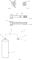
- a breathing system 10 comprising:
- intermediate pressure is understood as the pressure between the first and second stages 91, 92 (and, therefore, in the preferred application, the pressure immediately upstream of the system 1).
- the intermediate pressure can be equal to about 10 bar (though it may vary for example with depth).
- the reducing system 1 comprises a supply conduit 2 for supplying a pressurised breathable gas.
- the supply conduit 2 typically originates from the tube 93 coming from the first stage connected to the pressurised tank 9 of breathable fluid (the gas could also be in liquid form inside the tank 9).
- the breathable gas can be of various types: compressed air, nitrox, mixtures of oxygen, nitrogen and helium, or still others.
- the system 1 also comprises a suction mouthpiece 3 for a user to breathe in the breathable gas. This enables the user to keep the second stage firmly in his or her mouth and thus to breathe.
- the system 1 comprises a valve 4 interposed between the supply conduit 2 and the suction mouthpiece 3.
- the valve 4 in turn comprises:
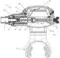
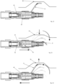
- the valve 4 also comprises a shutter 43 that is movable between a first position (see for example figure 13 ) and a second position (see for example figure 14 ) in which it respectively permits or prevents the passage of the breathable gas from the inlet 41 to the outlet 42.
- a second position see for example figure 14
- the second position is also exemplified in figures 3 , 4 , 5 , 6 , 7 , 8 , 23 , 25 .
- the shutter 43 In the first position the shutter 43 is distanced from the inlet 41 (see figure 1 ; with reference to figures 3 , 4 , 5 , 6 , 7 , 8 , 23 , 25 this means that it is shifted towards the right compared to the image represented).
- the shutter 43 In the first position the shutter 43 is thus distanced from the inlet 41.
- the shutter 43 In a zone intended to come into contact with the inlet 41 the shutter 43 comprises a sealing element 410.
- the sealing element 410 is called “pad” in technical jargon.
- the inlet 41 against which the pad is pressed can leave an imprint on the latter (called “marking” in technical jargon).
- the inlet 41 can typically have a thin profile 411 to optimise the seal with the pad.
- the valve 4 comprises a pressure balancing chamber 44.
- the expression "balancing chamber 44" is well known in the technical field, as during operation it enables at least a partial balancing of the force exerted by the pressure at the inlet 41. In the specific case, conveniently, no elastic spring is present between the shutter 43 and the balancing chamber 44.
- the shutter 43 is interposed between the inlet 41 of the valve 4 and the balancing chamber 44.
- the shutter 43 defines a passage 430 that places the inlet 41 of the valve 4 and the pressure balancing chamber 44 in fluid communication.
- the passage 430 extends inside the shutter 43.
- the passage 430 can have an outflow cross section of a size comprised between 1 mm 2 and 2 mm 2 .
- the balancing chamber 44 takes on the pressure value existing at the inlet 41 of the valve 4. This is thanks to the gas that flows from the inlet 41 to the chamber 44 by means of the passage 430.
- the gas also flows outside the shutter 43 to the outlet 42. In this case the gas flows in a space interposed between the shutter 43 and a seat 7 that laterally surrounds the shutter 43.
- the outlet 42 is advantageously obtained on a wall of the seat 7.
- the balancing chamber 44 is kept in a fixed position (towards the right for example in figure 1 ). This occurs by virtue of the intermediate pressure acting on the wall 440.
- the shutter 43 is shifted from the second to the first position as a consequence of the negative pressure caused on the mouthpiece 3 by the user, who draws gas in order to breathe it in (see figure 13 ).
- the shutter 43 returns from the first to the second position due to the pressure exerted by the balancing chamber 44 (see figure 14 ).
- the pressure in the balancing chamber 44 is the same as the pressure at the inlet 41, but the force that causes the shutter 43 to close is greater than the one opposing it (as a consequence of the fact that the pushing surface that is usable in a closing direction of the shutter 43 is larger than the pushing surface that is usable in the opening direction; this is because inside the chamber 44 the shutter 43 has a pushing surface for closing that is larger than the surface of the shutter 43 which in the second position faces the section for the passage of gas into the inlet 41).
- the system 1 also comprises a movement system 5 for moving the balancing chamber 44 towards the inlet 41 for the breathable gas to push the shutter 43 from the first to the second position, for example on the occurrence of preset operating conditions (typically depressurisation or blockage of the shutter 43 as a result of freezing).
- preset operating conditions typically depressurisation or blockage of the shutter 43 as a result of freezing.
- the movement system 5 intervenes spontaneously in the event of there being a depressurisation immediately upstream of the inlet 41 (depressurisation of the second stage typically occurs when the pressure immediately upstream of the inlet 41 is brought to "ambient pressure") or enables a manual intervention of the user in the event of occurrence of freezing which blocks the shifting of the shutter 43.
- the balancing chamber 44 is therefore movable relative to the inlet 41 (although the movement in actual fact takes places place only under certain conditions).
- the movement means 5 induces the movement of the shutter 43 from the first to the second position as a consequence of the push received by the balancing chamber 44 in its stroke towards the inlet 41 (thus the movement system 5 pushes the balancing chamber 44, which in turn pushes the shutter 43).
- the balancing chamber 44 is conveniently shaped like a cup having an opening through which the shutter 43 is inserted.
- the end of the shutter 43 that extends into the balancing chamber 44 comprises an annular gasket 99 (O-ring).
- a back wall 440 of the balancing chamber is intended to push the shutter 43 against the inlet 41. Therefore, the system 1 can take on a configuration in which the back wall 440 of the balancing chamber 44 abuts against and pushes the shutter 43 towards the second (closed) position.
- the balancing chamber 44 slides along the seat 7 under the action of the movement system 5. In particular, the balancing chamber 44 slides along the seat 7 parallel to a preponderant direction of extension of the shutter 43.
- the movement system 5 for moving the balancing chamber 44 can be of varying type.
- the system 5 is external to the balancing chamber 44.
- the balancing chamber 44 is interposed between the shutter 43 and the movement means 5.
- the movement system 5 typically comprises/coincides with a means for pushing the balancing chamber 44.
- the movement system 5 comprises/coincides with an elastic means 50 that exerts a force which pushes the balancing chamber 44 towards the inlet 41 of the valve 4.
- This force manifests itself concretely in an actual movement when the system is depressurised.
- the elastic means 50 comprises a spring, typically a helical spring.
- the elastic means 50 is external to the balancing chamber 44.
- the balancing chamber 44 is interposed between the elastic means 50 and the shutter 43.
- the elastic means 50 pushes on a rear wall (back wall 440) of the balancing chamber 44.
- the elastic means 50 is such as to offer a lesser force than is exerted by the intermediate pressure on the back wall 440 of the balancing chamber 44; consequently, it does not intervene in the operation of the system 1 if pressurised. However, when the line is purged (is depressurised upstream of the valve 4, see figure 11 ) the elastic means 50 enables the shutter 43 to be repositioned in (drawn into) the second position (closed position of the valve 4).
- the elastic means 50 could be such that in the second position (closed position of the valve 4, i.e. when the elastic means 50 is in the configuration of minimum compression) it exerts a minimal force (so as to minimise the marking of the pad, a drawback described previously).
- This effect can be optimised, given that when the spring expands the force it exerts decreases, and thus the spring can be designed in such a way as to provide a sufficient force to initiate the movement of the balancing chamber 44, but such that after the travel stroke thereof (for example about 2 millimetres) the residual force is just sufficient to prevent the entry of water towards the first stage during rinsing.
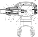
- the system 1 can comprise a means 90 for regulating a maximum stroke of the shutter 43 (appropriately between the first and second positions).
- the regulating means 90 comprises a pusher 901 intended to abut against (directly or through the interposition of other means) a wall of the balancing chamber 44 (in particular the back wall 440).
- the pusher 901 can regulate/limit the position of maximum distancing of the balancing chamber 44 from the inlet 41.
- the pusher 901 is shaped like a rod.
- the pusher 901 acts on the balancing chamber 44 so as to regulate the maximum stroke of the shutter 43 accordingly.
- the elastic means 50 surrounds at least a portion of the pusher 901.
- the pusher 901 extends from the balancing chamber 44 in an opposite direction relative to the shutter 43.
- the pusher 901 and the shutter 43 are intended to move along a same direction 903.
- the system 1 comprises a casing 902 in which the valve 4 and/or the balancing chamber 44 are placed.
- the pusher 901 is intended to abut against the balancing chamber 44 and limit the stroke of the shutter 43 accordingly; in particular, the pusher 901 can regulate/limit the position of maximum distancing of the balancing chamber 44 from the inlet 41 of the valve 4 (in this regard, the pusher 901 can advantageously be stably regulated in a plurality of positions).
- the pusher 901 comes into contact with the balancing chamber 44 inside the casing 902.
- the means 90 for regulating the maximum stroke of the shutter 43 also comprises a system 904 for controlling the pusher 901.
- the control system 904 allows the pusher to be stably positioned in a plurality of positions so as to regulate the position of maximum distancing of the balancing chamber 44 from the inlet 41 of the valve 4.
- the control system 904 is movable between a first configuration and a second configuration. The shifting between the first and second configurations takes place manually.
- a reduced stroke of the shutter 43 between the first and second positions is associated with the first configuration (see figures 22, 23 , 26, 27 ).
- An extended stroke of the shutter 43 between the first and second positions is associated with the second configuration (see figures 24, 25 , 28, 29 ).
- the action of the pusher 901 could be superfluous, since the position of maximum distancing of the balancing chamber 44 from the inlet 41 of the valve 4 could be imposed by an additional retaining element 449 (for example an annular wall as illustrated by way of example in figure 28 ). Therefore, in the second configuration the pusher 901 does not necessarily abut against the back wall 440.
- the balancing chamber 44, in particular the back wall 440, is intended to push the pusher 901 away from the shutter 43 or in any case away from the inlet 41 of the valve 4.
- the control system 904 comprises a first abutment 905, which, in the first configuration, opposes the distancing of the pusher 901 from the inlet 41 of the valve 4 (in other words towards the outside of the casing 902). In the first configuration the first abutment 905 is in contact with a first stop element 907 of the pusher 901.
- the control system 904 comprises a second abutment 906, which, in the second configuration opposes the distancing of the pusher 901 from the inlet 41 of the valve 4 (in other words, towards the outside of the casing 902).
- the second abutment 906 In the second configuration the second abutment 906 is in contact with a second stop element 908 of the pusher 901.
- the first abutment 905 is not in contact with the first stop element 907 of the pusher 901.
- the first and second stop elements 907, 908 are advantageously obtained on a same annular protrusion 910 of the pusher 901.
- the second abutment 906 is more external than the first abutment 905.
- the distance of the first abutment 905 from the inlet 401 of the valve 4 is smaller than the distance of the second abutment 906 from the inlet 401 (or at least this condition is met if one evaluates only the component of the distance along the direction 903).
- the control system 904 comprises a selector 909 integrating the first and second abutments 905, 906. In particular, they could be integrated into a single unassembled body. As exemplified in figures 22-24 , the selector 909 is movable. A shifting of the selector 909 makes it possible to move the pusher 901 and pass from the second to the first configuration. Conveniently, the selector 909 interacts with the annular protrusion 910 to bring about the movement of the pusher 901 and the passage from the second to the first configuration. In an alternative solution, not illustrated, the selector 909 can be rotated so as to pass from the first to the second configuration and vice versa. For example, there could be a lever with a cam profile.
- the pusher 901 is forced towards the inside of the casing 902 for a length comprised between 1.5 and 1.9 millimetres compared to the second configuration.
- the stroke of the shutter 43 can be comprised between 2 and 2.5 millimetres.
- the purpose of this regulation is to limit the outflow of breathable gas in situations where the second stage is necessarily made to supply air automatically; for example an instructor on the surface with a student in difficulty, who thus makes abrupt movements without the second stage in his or her mouth; in fact, in such a situation the second stage could be activated due to repeated striking of the same on the surface of the water).
- the configuration with a reduced stroke there would be a sufficient flow of gas to assure breathing at least down to 10 metres of depth.
- the means 90 for regulating a maximum stroke of the shutter 43 is exemplified as an optimisation of the solution in figures 1 and 2 , but, for example, it can also be applied to the other solutions illustrated or described.
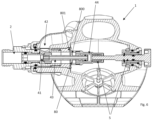
- the movement system 5 for moving the balancing chamber 44 conveniently comprises a manual push actuator 51 for pushing the balancing chamber 44 towards the inlet 41 of the valve 4.
- the actuator 51 projects outside the second stage, making it accessible by a user.
- the actuator 51 is for example a pusher. Therefore, by manually pushing the actuator 51, the user moves the balancing chamber 44, which in turn pushes the shutter 43 from the first to the second position.
- the user can act manually on the actuator 51 before rinsing the system 1, before pressurising the system (to ensure that the shutter 43 is in the closed position) or under emergency conditions should the shutter be blocked due to freezing (as explained in greater detail below).
- the valve 4 is closed by repositioning the shutter 43 in the second position.
- the actuator 51 is in a single body or assembled with the balancing chamber 44.
- the actuator 51 and the chamber 44 could be connected by means of an intermediate mechanism (solution not illustrated).
- the actuator 51 passes through the elastic means 50.
- This solution can thus be understood as a combination of the solution in figure 1 and the one in figure 3 .
- the balancing chamber 44 is movable towards the inlet 41 of the valve 4 both by means of the actuator 51 and by means of the elastic means 50.
- the actuator 51 passes through a helical spring that is part of the elastic means 50.
- the movement system 5 thus comprises a manual actuator 51 and a mechanical spring 50 (the latter being absent, by contrast, in the solution of figure 3 ).
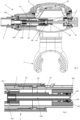
- the movement system 5 for moving the balancing chamber 44 comprises an auxiliary chamber 6 placed in fluid communication with said balancing chamber 44. Conveniently, this takes place by means of a channel 60 having an outflow cross section of reduced size.
- the cross section could be less than 1 mm 2 or less than half of the outflow cross section of the passage 430.
- the outflow cross sections are determined orthogonally to the direction of the fluid outflow. If they are not constant along the longitudinal extent, the minimum cross section can be taken into consideration.
- the balancing chamber 44 is thus interposed between the auxiliary chamber 6 and the shutter 43. When the system 1 is pressurised, in addition to the chamber 44 being pressurised, the chamber 6 is pressurised more slowly.
- the net effect of the pressurisation is that the balancing chamber 44 is distanced from the inlet 41 (i.e. it is shifted towards the right in the image in figure 7 ).
- the chamber 6 thus becomes a chamber with an intermediate pressure (the pressure between the first and second stages).
- the balancing chamber 44 will release the pressure through the passage 430 much more quickly compared to the auxiliary chamber 6 (the difference in speed is induced by the fact that the channel 60 has a reduced outflow cross section). A force is thus generated which pushes the chamber 44 towards the inlet 41 (i.e.
- the movement system 5 is similar to the one in figure 7 , but instead of being based on reduced cross sections to differentiate the speed of depressurisation of the chambers 44 and 6, it exploits a one-way valve 61 and a vent valve 62.
- the movement system 5 comprises:
- the auxiliary chamber 6 can comprise a vent valve 62 for venting pressure when a pressure threshold is exceeded. It thus operates as an overpressure relief valve. With an appropriate setting of the overpressure tolerated prior to venting, this makes it possible to avoid the drawbacks described earlier in the case of a reascent from depths that could impact the regular operation of the system 1. In fact, the pressure upstream of the pressure-reducing system 1 (i.e. the pressure between the first and second stages) increases with increasing depth. Therefore, at great depths there could be higher pressures in the auxiliary chamber 6 than foreseen at lesser depths.
- the vent valve 62 can be set at a pressure that is greater than the sum of the ambient pressure and intermediate pressure; for example, the vent valve 62 can be activated when the sum of the ambient pressure and intermediate pressure is exceeded by a preset amount; this preset amount could for example be a value comprised between 0.5 and 1 bar.
- a first of such features regards the shutter 43, which extends between a first and a second end 431, 432.
- the first end 431 is nearer the inlet 41 of the valve 4 than the second end 432.
- the second end 432 comprises a flat surface 433 which is orthogonal to a direction 45 of shifting of the shutter 43 between the first and second positions.
- a groove 434 is obtained on the flat surface 433 and intersects the passage 430.
- the passage 430 and the groove 434 extend along two reciprocally transverse, or rather orthogonal, directions. The groove 434 enables the exit of the gas from the passage 430 to be facilitated when the flat surface 433 comes to abut against a facing surface obtained in the balancing chamber 44.
- the pressure-reducing system 1 comprises a seat 7 for housing the shutter 43.
- the pressure-reducing system 1 comprises a seat 7 housing at least a first section 435 of the shutter 43 comprising the first end 431.
- the first section 435 of the shutter 43 comprises a head that is sufficiently wide and long to accommodate the pad 410.
- the first section 435 also comprises a plurality of centring fins 436 that extend towards a wall 70 delimiting the seat 7.
- the fins 436 enable, in fact, the correct positioning of a longitudinal axis of the shutter 43 with a longitudinal axis of the seat 7.
- the presence of fins 436 rather than a full surface perfectly matching in shape with the transverse profile of the seat 7 makes it possible to facilitate the passage of gas between one fin and the other.
- the fins 436 have a portion turned towards the inlet 41 of the valve 4 which is rounded or bevelled. This allows for reducing resistance to the movement of the shutter 43 (sharp edge that "scrapes") as well as to the passage of gas. In fact, the greater such resistance is, the more difficult the passage of the shutter 43 from the first to the second position will be (i.e. the more difficult it will be to close the shutter 43).
- the rounding is also present on the other extremity of the fins 436, in this case for the sole purpose of preventing a sharp edge from scraping against the inner wall of the seat 7.
- the pressure-reducing system 1 comprises a lever 8 for shifting the shutter 43 between the first and second positions.
- the reducing system 1 comprises a diaphragm 82 which is deformable by the user's breathing in.
- the user brings about a negative pressure that deforms the deformable diaphragm 82, causing it in turn to shift the lever 8 (see figure 13 ).
- This induces a shifting of the shutter 43 from the second position to the first position, thereby permitting the passage of the breathable gas.
- the lever 8 goes back into the original position (see figure 14 ).
- the shutter 43 comprises a means 80 of interacting with the lever 8.
- the interacting means 80 can comprise a wall 800 against which one or more feet 801 of the lever 8 can rest. When the lever 8 is rotated, the feet 801 rotate and, being opposed on one side, they push the shutter 43 from the second to the first position (they open the shutter 43).
- the shutter 43 also comprises a flat zone 81 that extends longitudinally parallel to a preponderant direction of extension 46 of the shutter 43.
- the flat zone 81 connects the fins 436 and the interacting means 80.
- the flat zone 81 has the purpose of minimising the risk of oscillations of the shutter 43 during opening. In fact, when the shutter 43 passes from the second to the first (open) position, the gas coming from the inlet 41 is introduced not only into the passage 430, but also flows outside the shutter 43.
- Every protuberance/wall of the shutter perpendicular to the direction of flow outside the shutter itself acts like a "sail” which, when struck by the flow of gas, causes the shutter 43 to move rearward and disrupts the correct movement thereof. This can bring about undesirable uncertainties in the shifting of the shutter 43.
- the subject matter of the present invention further relates to a method for operating the system 1 (having one or more of the features specified previously).
- the method comprises a step of pushing the balancing chamber 44 towards the inlet 41 of the breathable gas when the system is depressurised (i.e. when there is a pressure drop immediately upstream of the inlet 41, typically when the pressure in that zone becomes equal to the outside ambient pressure, in particular it becomes equal to atmospheric pressure). This takes place by means of the movement system 5. This brings about the passage of the shutter 43 from the first position, in which it permits the outflow of the gas through the valve 4, to the second position in which the flow is interrupted.
Landscapes
- Health & Medical Sciences (AREA)
- General Health & Medical Sciences (AREA)
- Pulmonology (AREA)
- Engineering & Computer Science (AREA)
- Mechanical Engineering (AREA)
- Ocean & Marine Engineering (AREA)
- Respiratory Apparatuses And Protective Means (AREA)
Claims (13)
- Druckminderungssystem für ein Atemgerät, umfassend:i) eine Zuleitung (2) zum Zuführen eines mit Druck beaufschlagten Atemgases;ii) ein Saugmundstück (3) für einen Nutzer, um das Atemgas einzuatmen;iii) ein Ventil (4), das zwischen der Zuleitung (2) und dem Saugmundstück (3) eingesetzt ist, wobei das Ventil (4) seinerseits Folgendes umfasst:dadurch gekennzeichnet, dass das Minderungssystem (1) ein Bewegungssystem (5) zum Bewegen der Druckausgleichskammer (44) hinführend zum Einlass (41) für das Atemgas umfasst, um den Schließer (43) von der ersten Position in die zweite Position zu bewegen, wenn mindestens eine voreingestellte Betriebsbedingung auftritt.- einen Einlass (41) für das aus der Zuleitung (2) einströmende Atemgas;- einen Auslass (42) für das zum Saugmundstück (3) geleitete Atemgas;- einen Schließer (43), der zwischen einer ersten und einer zweiten Position bewegbar ist, in denen er jeweils das Durchströmen des Atemgases vom Einlass (41) zum Auslass (42) erlaubt bzw. unterbindet;- eine Druckausgleichskammer (44), wobei der Schließer (43) teilweise zwischen dem Einlass (41) des Ventils (4) und der Ausgleichskammer (44) eingesetzt ist, wobei der Schließer (43) einen Durchgang (430) definiert, der den Einlass (41) des Ventils (4) und die Druckausgleichskammer (44) in Fluidkommunikation setzt, wobei zwischen dem Schließer (43) und der Druckausgleichskammer (44) keine mechanische Feder befindlich ist,
- Druckminderungssystem nach Anspruch 1, dadurch gekennzeichnet, dass das Bewegungssystem (5) elastische Mittel (50) umfasst, die die Druckausgleichskammer (44) hinführend zum Einlass (41) des Ventils (4) schieben.
- Druckminderungssystem nach Anspruch 1 oder 2, dadurch gekennzeichnet, dass das Bewegungssystem (5) einen manuellen Schiebeaktuator (51) umfasst, um die Druckausgleichskammer (44) hinführend zum Einlass (41) des Ventils (4) zu schieben, wobei der Aktuator (51) für einen Nutzer zugänglich ist.
- Druckminderungssystem nach Anspruch 3, wenn abhängig von Anspruch 2, dadurch gekennzeichnet, dass der Aktuator (51) durch die elastischen Mittel (50) führt und die Druckausgleichskammer (44) hinführend zum Einlass (41) des Ventils (4) sowohl mittels des Aktuators (51) als auch mittels der elastischen Mittel (50) bewegbar ist.
- Druckminderungssystem nach einem der vorhergehenden Ansprüche, dadurch gekennzeichnet, dass das Bewegungssystem (5) zum Bewegen der Druckausgleichskammer (44) eine Hilfskammer (6) umfasst, wobei die Hilfskammer (6) mit der Ausgleichskammer (44) durch einen Kanal (60), aufweisend einen Ausströmungsquerschnitt einer Größe, die halb so groß ist wie die des Ausströmungsquerschnitts des Durchgangs (430), in Fluidkommunikation gesetzt ist.
- Druckminderungssystem nach einem der Ansprüche 1 bis 4, dadurch gekennzeichnet, dass das Bewegungssystem (5) zum Bewegen der Druckausgleichskammer (44) Folgendes umfasst:- eine Hilfskammer (6);- ein Rückschlagventil (61), das das Ausströmen von der Druckausgleichskammer (44) zur Hilfskammer (6) ermöglicht,wobei die Hilfskammer (6) ein Entlüftungsventil (62) für den Abbau von Druck umfasst, wenn ein Druckschwellenwert überschritten ist.
- Druckminderungssystem nach einem der vorhergehenden Ansprüche, dadurch gekennzeichnet, dass sich der Schließer (43) zwischen einem ersten und einem zweiten Ende (431, 432) erstreckt, wobei das erste Ende (431) näher am Einlass (41) des Ventils (4) ist als das zweite Ende (432),
wobei das zweite Ende (432) eine flache Oberfläche (433) umfasst, die rechtwinkelig zu einer Verschieberichtung (45) des Schließers (43) zwischen der ersten und der zweiten Position angeordnet ist, wobei auf der flachen Oberfläche (433) eine Rille (434) ausgebildet ist, die sich am Durchgang (430) erstreckt. - Druckminderungssystem nach einem der vorhergehenden Ansprüche, dadurch gekennzeichnet, dass es eine Aufnahme (7) umfasst, in der mindestens eine erste Sektion (435) des Schließers (43) untergebracht ist, die sich näher am Einlass (41) befindet, wobei die erste Sektion (435) des Schließers (43) eine Vielzahl von Zentrierrippen (436) umfasst, die sich hinführend zu einer Wand (70) erstrecken, die die Aufnahme (7) abgrenzt, um den Schließer (43) korrekt zum Einlass (41) des Ventils (4) auszurichten.
- Druckminderungssystem nach einem der vorhergehenden Ansprüche, dadurch gekennzeichnet, dass es einen Hebel (8) umfasst, um den Schließer (43) zwischen der ersten und der zweiten Position zu verschieben,
wobei der Schließer (43) Folgendes umfasst:- Mittel (80) zum Interagieren mit dem Hebel (8);- eine flache Zone (81), die sich längsseitig parallel zu einer vorwiegenden Ausdehnungsrichtung (46) des Schließers (43) erstreckt und die Rippen (436) und die Mittel (80) zum Interagieren mit dem Hebel (8) verbindet. - Druckminderungssystem nach einem der vorhergehenden Ansprüche, dadurch gekennzeichnet, dass es Mittel (90) zum Regulieren eines maximalen Hubs des Schließers (43) umfasst, wobei die Regulierungsmittel einen Schieber (901) umfassen, der dazu bestimmt ist, an einer Wand der Druckausgleichskammer in Anschlag zu gelangen, um die Position der maximalen Beabstandung der Druckausgleichskammer (44) vom Einlass (41) zu regulieren/begrenzen.
- Druckminderungssystem nach Anspruch 10, dadurch gekennzeichnet, dass die Regulierungsmittel (90) ein Steuerungssystem (904) umfassen, das zum stabilen Positionieren des Schiebers (901) in einer Vielzahl von Positionen der maximalen Beabstandung der Druckausgleichskammer (44) vom Einlass (41) des Ventils (4) geeignet ist.
- Atemsystem, umfassend:- einen Behälter (9) mit Atemgas;- eine erste Druckminderungsstufe (91), die sich stromabwärts des Behälters (9) befindet;- eine zweite Druckminderungsstufe (92), die sich stromabwärts der ersten Stufe (91) befindet und ein Druckminderungssystem (1) nach einem der Ansprüche 1 bis 11 umfasst;- ein Rohr (93), das die erste Stufe (91) mit der zweiten Stufe (92) verbindet und in dem sich das Gas bewegt.
- Verfahren zur Bedienung eines Druckminderungssystems nach einem oder mehreren der Ansprüche 1 bis 11, wenn ein ausreichender Druckverlust unmittelbar stromaufwärts des Einlasses (41) erfolgt, wobei das Verfahren, wenn der Druckverlust erfolgt, den Schritt zum spontanen Schieben der Ausgleichskammer (44) hinführend zum Einlass (41) für das Atemgas mittels des Bewegungssystems (5) umfasst, wodurch der Übergang des Schließers (43) von der ersten Position, in der er das Ausströmen des Gases durch das Ventil (4) ermöglicht, in die zweite Position, in der der Strom unterbrochen ist, herbeigeführt wird.
Priority Applications (1)
| Application Number | Priority Date | Filing Date | Title |
|---|---|---|---|
| US18/169,912 US12595033B2 (en) | 2022-03-02 | 2023-02-16 | Pressure-reducing system for a breathing apparatus |
Applications Claiming Priority (1)
| Application Number | Priority Date | Filing Date | Title |
|---|---|---|---|
| IT102022000003899A IT202200003899A1 (it) | 2022-03-02 | 2022-03-02 | Sistema di riduzione di pressione per un apparato di respirazione |
Publications (3)
| Publication Number | Publication Date |
|---|---|
| EP4238864A1 EP4238864A1 (de) | 2023-09-06 |
| EP4238864B1 true EP4238864B1 (de) | 2024-05-29 |
| EP4238864C0 EP4238864C0 (de) | 2024-05-29 |
Family
ID=81648871
Family Applications (1)
| Application Number | Title | Priority Date | Filing Date |
|---|---|---|---|
| EP23153097.3A Active EP4238864B1 (de) | 2022-03-02 | 2023-01-24 | Druckminderungssystem für ein atemgerät |
Country Status (3)
| Country | Link |
|---|---|
| US (1) | US12595033B2 (de) |
| EP (1) | EP4238864B1 (de) |
| IT (1) | IT202200003899A1 (de) |
Families Citing this family (1)
| Publication number | Priority date | Publication date | Assignee | Title |
|---|---|---|---|---|
| EP4656508A1 (de) | 2024-05-30 | 2025-12-03 | Mares S.p.A. | Druckminderungssystem für ein atemgerät |
Family Cites Families (18)
| Publication number | Priority date | Publication date | Assignee | Title |
|---|---|---|---|---|
| US3329158A (en) * | 1964-03-20 | 1967-07-04 | Us Divers Co Inc | Balanced, single stage-single hose regulator |
| CH608718A5 (de) * | 1975-01-20 | 1979-01-31 | Scubapro Eu | |
| US4002166A (en) | 1975-04-23 | 1977-01-11 | Amf Incorporated | Bypassed scuba regulator |
| US5251618A (en) * | 1987-09-30 | 1993-10-12 | Tony Christianson | Regulator second stage for scuba |
| JPH0557031A (ja) * | 1991-02-04 | 1993-03-09 | Us Divers Co Inc | デマンド呼吸用二次レギユレーター |
| US5222490A (en) * | 1991-09-26 | 1993-06-29 | Dacor Corporation | Breathing regulator having air injector feature |
| EP0534741B1 (de) * | 1991-09-26 | 1996-11-13 | Dacor Corporation | Atemregulator mit Luftinjektion |
| US5233976A (en) * | 1992-04-27 | 1993-08-10 | Dacor Corporation | Second stage regulator hose with built-in cone adjusting tool |
| US5259375A (en) * | 1992-06-19 | 1993-11-09 | Manfred Schuler | Second stage scuba regulator with balanced piston volume control |
| US5660502A (en) * | 1995-02-08 | 1997-08-26 | American Underwater Products, Inc. | Adjustment mechanism for a scuba second stage airflow regulator |
| US5549107A (en) * | 1995-08-08 | 1996-08-27 | Under Sea Industries, Inc. | Second stage scuba diving regulator |
| US5803073A (en) * | 1996-03-08 | 1998-09-08 | Toth; Douglas J. | Second stage scuba diving regulator having a pneumatic-dependent anti-set feature |
| US5678541A (en) * | 1996-03-15 | 1997-10-21 | Garraffa; Dean R. | Breathing regulator apparatus having automatic flow control |
| US5690100A (en) * | 1996-08-23 | 1997-11-25 | Johnson Worldwide Assoc., Inc. | Scuba diving breathing regulator |
| ITSV20030005A1 (it) * | 2003-02-11 | 2004-08-12 | Scubapro Europ | Secondo stadio di riduzione della pressione in erogatori |
| US7171980B2 (en) | 2004-06-18 | 2007-02-06 | Johnson Outdoors Inc. | Springless regulator valve assembly |
| GB2443392B (en) * | 2006-11-01 | 2011-06-08 | Clipper Data Ltd | Pressure regulator valve for breathing apparatus |
| US8336547B1 (en) * | 2012-01-20 | 2012-12-25 | Amron International, Inc. | Breathing mask |
-
2022
- 2022-03-02 IT IT102022000003899A patent/IT202200003899A1/it unknown
-
2023
- 2023-01-24 EP EP23153097.3A patent/EP4238864B1/de active Active
- 2023-02-16 US US18/169,912 patent/US12595033B2/en active Active
Also Published As
| Publication number | Publication date |
|---|---|
| EP4238864C0 (de) | 2024-05-29 |
| US20230278683A1 (en) | 2023-09-07 |
| EP4238864A1 (de) | 2023-09-06 |
| IT202200003899A1 (it) | 2023-09-02 |
| US12595033B2 (en) | 2026-04-07 |
Similar Documents
| Publication | Publication Date | Title |
|---|---|---|
| EP4238864B1 (de) | Druckminderungssystem für ein atemgerät | |
| EP2720105B1 (de) | Mehrstufiger Druckregler. | |
| RU2667045C2 (ru) | Регулятор текучей среды с интегрированным перепускным клапаном для быстрого создания давления | |
| US3898705A (en) | Convertible inflation control for underwater diving vests | |
| US3866253A (en) | Divers buoyancy vest | |
| EP2819753B1 (de) | Luftfluss kontrollventil | |
| KR20130113416A (ko) | 충전 커넥터, 상응하는 컨테이너 및 상응하는 충전 방법 | |
| CN1300228A (zh) | 可迅速佩带的保护性呼吸装置 | |
| US20190353263A1 (en) | Poppet type pneumatic valve for inflation system | |
| EP0134447B1 (de) | Ventil für Hochdruckbehälter | |
| US20180072117A1 (en) | Rapid Opening Gas Valve | |
| US5803073A (en) | Second stage scuba diving regulator having a pneumatic-dependent anti-set feature | |
| US5549107A (en) | Second stage scuba diving regulator | |
| JP7357933B2 (ja) | 圧力リリーフバルブアセンブリ | |
| US20150020799A1 (en) | Integrated diving snorkel and regulator and methods of use | |
| US11306743B2 (en) | Aspirator integrated pressure relief valve and vent valve for an inflation system | |
| US4413645A (en) | Fluid swivel valve device | |
| US11149906B2 (en) | Valve, pressurized fluid container, and filling and withdrawal methods | |
| CA2339733A1 (en) | System for loading and unloading fluid tanks containing hazardous fluids | |
| US7322372B2 (en) | Fire-fighting monitor with remote control | |
| EP4306402A1 (de) | Druckminderungssystem für ein atemgerät | |
| EP3329159B1 (de) | Ventil | |
| US9663203B2 (en) | Buoyancy vest vent valve with reliable seating | |
| US6257275B1 (en) | Pressure reducing valve | |
| US7171980B2 (en) | Springless regulator valve assembly |
Legal Events
| Date | Code | Title | Description |
|---|---|---|---|
| PUAI | Public reference made under article 153(3) epc to a published international application that has entered the european phase |
Free format text: ORIGINAL CODE: 0009012 |
|
| STAA | Information on the status of an ep patent application or granted ep patent |
Free format text: STATUS: REQUEST FOR EXAMINATION WAS MADE |
|
| 17P | Request for examination filed |
Effective date: 20230803 |
|
| AK | Designated contracting states |
Kind code of ref document: A1 Designated state(s): AL AT BE BG CH CY CZ DE DK EE ES FI FR GB GR HR HU IE IS IT LI LT LU LV MC ME MK MT NL NO PL PT RO RS SE SI SK SM TR |
|
| P01 | Opt-out of the competence of the unified patent court (upc) registered |
Effective date: 20231010 |
|
| GRAP | Despatch of communication of intention to grant a patent |
Free format text: ORIGINAL CODE: EPIDOSNIGR1 |
|
| STAA | Information on the status of an ep patent application or granted ep patent |
Free format text: STATUS: GRANT OF PATENT IS INTENDED |
|
| INTG | Intention to grant announced |
Effective date: 20240124 |
|
| GRAS | Grant fee paid |
Free format text: ORIGINAL CODE: EPIDOSNIGR3 |
|
| GRAA | (expected) grant |
Free format text: ORIGINAL CODE: 0009210 |
|
| STAA | Information on the status of an ep patent application or granted ep patent |
Free format text: STATUS: THE PATENT HAS BEEN GRANTED |
|
| AK | Designated contracting states |
Kind code of ref document: B1 Designated state(s): AL AT BE BG CH CY CZ DE DK EE ES FI FR GB GR HR HU IE IS IT LI LT LU LV MC ME MK MT NL NO PL PT RO RS SE SI SK SM TR |
|
| REG | Reference to a national code |
Ref country code: CH Ref legal event code: EP |
|
| REG | Reference to a national code |
Ref country code: IE Ref legal event code: FG4D |
|
| REG | Reference to a national code |
Ref country code: DE Ref legal event code: R096 Ref document number: 602023000110 Country of ref document: DE |
|
| U01 | Request for unitary effect filed |
Effective date: 20240530 |
|
| U07 | Unitary effect registered |
Designated state(s): AT BE BG DE DK EE FI FR IT LT LU LV MT NL PT SE SI Effective date: 20240610 |
|
| P04 | Withdrawal of opt-out of the competence of the unified patent court (upc) registered |
Free format text: CASE NUMBER: APP_33763/2024 Effective date: 20240605 |
|
| PG25 | Lapsed in a contracting state [announced via postgrant information from national office to epo] |
Ref country code: IS Free format text: LAPSE BECAUSE OF FAILURE TO SUBMIT A TRANSLATION OF THE DESCRIPTION OR TO PAY THE FEE WITHIN THE PRESCRIBED TIME-LIMIT Effective date: 20240929 |
|
| PG25 | Lapsed in a contracting state [announced via postgrant information from national office to epo] |
Ref country code: HR Free format text: LAPSE BECAUSE OF FAILURE TO SUBMIT A TRANSLATION OF THE DESCRIPTION OR TO PAY THE FEE WITHIN THE PRESCRIBED TIME-LIMIT Effective date: 20240529 |
|
| PG25 | Lapsed in a contracting state [announced via postgrant information from national office to epo] |
Ref country code: GR Free format text: LAPSE BECAUSE OF FAILURE TO SUBMIT A TRANSLATION OF THE DESCRIPTION OR TO PAY THE FEE WITHIN THE PRESCRIBED TIME-LIMIT Effective date: 20240830 |
|
| PG25 | Lapsed in a contracting state [announced via postgrant information from national office to epo] |
Ref country code: ES Free format text: LAPSE BECAUSE OF FAILURE TO SUBMIT A TRANSLATION OF THE DESCRIPTION OR TO PAY THE FEE WITHIN THE PRESCRIBED TIME-LIMIT Effective date: 20240529 |
|
| PG25 | Lapsed in a contracting state [announced via postgrant information from national office to epo] |
Ref country code: PL Free format text: LAPSE BECAUSE OF FAILURE TO SUBMIT A TRANSLATION OF THE DESCRIPTION OR TO PAY THE FEE WITHIN THE PRESCRIBED TIME-LIMIT Effective date: 20240529 |
|
| PG25 | Lapsed in a contracting state [announced via postgrant information from national office to epo] |
Ref country code: PL Free format text: LAPSE BECAUSE OF FAILURE TO SUBMIT A TRANSLATION OF THE DESCRIPTION OR TO PAY THE FEE WITHIN THE PRESCRIBED TIME-LIMIT Effective date: 20240529 Ref country code: NO Free format text: LAPSE BECAUSE OF FAILURE TO SUBMIT A TRANSLATION OF THE DESCRIPTION OR TO PAY THE FEE WITHIN THE PRESCRIBED TIME-LIMIT Effective date: 20240829 Ref country code: IS Free format text: LAPSE BECAUSE OF FAILURE TO SUBMIT A TRANSLATION OF THE DESCRIPTION OR TO PAY THE FEE WITHIN THE PRESCRIBED TIME-LIMIT Effective date: 20240929 Ref country code: HR Free format text: LAPSE BECAUSE OF FAILURE TO SUBMIT A TRANSLATION OF THE DESCRIPTION OR TO PAY THE FEE WITHIN THE PRESCRIBED TIME-LIMIT Effective date: 20240529 Ref country code: GR Free format text: LAPSE BECAUSE OF FAILURE TO SUBMIT A TRANSLATION OF THE DESCRIPTION OR TO PAY THE FEE WITHIN THE PRESCRIBED TIME-LIMIT Effective date: 20240830 Ref country code: ES Free format text: LAPSE BECAUSE OF FAILURE TO SUBMIT A TRANSLATION OF THE DESCRIPTION OR TO PAY THE FEE WITHIN THE PRESCRIBED TIME-LIMIT Effective date: 20240529 Ref country code: RS Free format text: LAPSE BECAUSE OF FAILURE TO SUBMIT A TRANSLATION OF THE DESCRIPTION OR TO PAY THE FEE WITHIN THE PRESCRIBED TIME-LIMIT Effective date: 20240829 |
|
| P05 | Withdrawal of opt-out of the competence of the unified patent court (upc) changed |
Free format text: CASE NUMBER: APP_33763/2024 Effective date: 20240610 |
|
| PG25 | Lapsed in a contracting state [announced via postgrant information from national office to epo] |
Ref country code: CZ Free format text: LAPSE BECAUSE OF FAILURE TO SUBMIT A TRANSLATION OF THE DESCRIPTION OR TO PAY THE FEE WITHIN THE PRESCRIBED TIME-LIMIT Effective date: 20240529 |
|
| PG25 | Lapsed in a contracting state [announced via postgrant information from national office to epo] |
Ref country code: SK Free format text: LAPSE BECAUSE OF FAILURE TO SUBMIT A TRANSLATION OF THE DESCRIPTION OR TO PAY THE FEE WITHIN THE PRESCRIBED TIME-LIMIT Effective date: 20240529 Ref country code: RO Free format text: LAPSE BECAUSE OF FAILURE TO SUBMIT A TRANSLATION OF THE DESCRIPTION OR TO PAY THE FEE WITHIN THE PRESCRIBED TIME-LIMIT Effective date: 20240529 |
|
| PG25 | Lapsed in a contracting state [announced via postgrant information from national office to epo] |
Ref country code: SM Free format text: LAPSE BECAUSE OF FAILURE TO SUBMIT A TRANSLATION OF THE DESCRIPTION OR TO PAY THE FEE WITHIN THE PRESCRIBED TIME-LIMIT Effective date: 20240529 |
|
| PG25 | Lapsed in a contracting state [announced via postgrant information from national office to epo] |
Ref country code: SM Free format text: LAPSE BECAUSE OF FAILURE TO SUBMIT A TRANSLATION OF THE DESCRIPTION OR TO PAY THE FEE WITHIN THE PRESCRIBED TIME-LIMIT Effective date: 20240529 Ref country code: SK Free format text: LAPSE BECAUSE OF FAILURE TO SUBMIT A TRANSLATION OF THE DESCRIPTION OR TO PAY THE FEE WITHIN THE PRESCRIBED TIME-LIMIT Effective date: 20240529 Ref country code: RO Free format text: LAPSE BECAUSE OF FAILURE TO SUBMIT A TRANSLATION OF THE DESCRIPTION OR TO PAY THE FEE WITHIN THE PRESCRIBED TIME-LIMIT Effective date: 20240529 Ref country code: CZ Free format text: LAPSE BECAUSE OF FAILURE TO SUBMIT A TRANSLATION OF THE DESCRIPTION OR TO PAY THE FEE WITHIN THE PRESCRIBED TIME-LIMIT Effective date: 20240529 |
|
| U20 | Renewal fee for the european patent with unitary effect paid |
Year of fee payment: 3 Effective date: 20250130 |
|
| PLBE | No opposition filed within time limit |
Free format text: ORIGINAL CODE: 0009261 |
|
| STAA | Information on the status of an ep patent application or granted ep patent |
Free format text: STATUS: NO OPPOSITION FILED WITHIN TIME LIMIT |
|
| 26N | No opposition filed |
Effective date: 20250303 |
|
| PG25 | Lapsed in a contracting state [announced via postgrant information from national office to epo] |
Ref country code: MC Free format text: LAPSE BECAUSE OF FAILURE TO SUBMIT A TRANSLATION OF THE DESCRIPTION OR TO PAY THE FEE WITHIN THE PRESCRIBED TIME-LIMIT Effective date: 20240529 |
|
| U1H | Name or address of the proprietor changed after the registration of the unitary effect |
Owner name: HEAD WATERSPORTS S.P.A.; IT |
|
| PG25 | Lapsed in a contracting state [announced via postgrant information from national office to epo] |
Ref country code: IE Free format text: LAPSE BECAUSE OF NON-PAYMENT OF DUE FEES Effective date: 20250124 |
|
| U20 | Renewal fee for the european patent with unitary effect paid |
Year of fee payment: 4 Effective date: 20260128 |