EP4238862A1 - Floating offshore structure and floating offshore power generation apparatus having same - Google Patents
Floating offshore structure and floating offshore power generation apparatus having same Download PDFInfo
- Publication number
- EP4238862A1 EP4238862A1 EP21886812.3A EP21886812A EP4238862A1 EP 4238862 A1 EP4238862 A1 EP 4238862A1 EP 21886812 A EP21886812 A EP 21886812A EP 4238862 A1 EP4238862 A1 EP 4238862A1
- Authority
- EP
- European Patent Office
- Prior art keywords
- column
- pontoon
- floating offshore
- columns
- offshore structure
- Prior art date
- Legal status (The legal status is an assumption and is not a legal conclusion. Google has not performed a legal analysis and makes no representation as to the accuracy of the status listed.)
- Pending
Links
- 238000010248 power generation Methods 0.000 title claims abstract description 44
- XLYOFNOQVPJJNP-UHFFFAOYSA-N water Substances O XLYOFNOQVPJJNP-UHFFFAOYSA-N 0.000 description 12
- 230000007613 environmental effect Effects 0.000 description 4
- 238000005516 engineering process Methods 0.000 description 2
- 238000009434 installation Methods 0.000 description 2
- 238000004519 manufacturing process Methods 0.000 description 2
- 230000004048 modification Effects 0.000 description 2
- 238000012986 modification Methods 0.000 description 2
- 230000000694 effects Effects 0.000 description 1
- 230000005611 electricity Effects 0.000 description 1
- 206010016256 fatigue Diseases 0.000 description 1
- 230000002349 favourable effect Effects 0.000 description 1
- 239000002803 fossil fuel Substances 0.000 description 1
- 230000002787 reinforcement Effects 0.000 description 1
- 238000010792 warming Methods 0.000 description 1
Images



Classifications
-
- B—PERFORMING OPERATIONS; TRANSPORTING
- B63—SHIPS OR OTHER WATERBORNE VESSELS; RELATED EQUIPMENT
- B63B—SHIPS OR OTHER WATERBORNE VESSELS; EQUIPMENT FOR SHIPPING
- B63B35/00—Vessels or similar floating structures specially adapted for specific purposes and not otherwise provided for
- B63B35/44—Floating buildings, stores, drilling platforms, or workshops, e.g. carrying water-oil separating devices
-
- B—PERFORMING OPERATIONS; TRANSPORTING
- B63—SHIPS OR OTHER WATERBORNE VESSELS; RELATED EQUIPMENT
- B63B—SHIPS OR OTHER WATERBORNE VESSELS; EQUIPMENT FOR SHIPPING
- B63B1/00—Hydrodynamic or hydrostatic features of hulls or of hydrofoils
- B63B1/02—Hydrodynamic or hydrostatic features of hulls or of hydrofoils deriving lift mainly from water displacement
- B63B1/10—Hydrodynamic or hydrostatic features of hulls or of hydrofoils deriving lift mainly from water displacement with multiple hulls
- B63B1/107—Semi-submersibles; Small waterline area multiple hull vessels and the like, e.g. SWATH
-
- B—PERFORMING OPERATIONS; TRANSPORTING
- B63—SHIPS OR OTHER WATERBORNE VESSELS; RELATED EQUIPMENT
- B63B—SHIPS OR OTHER WATERBORNE VESSELS; EQUIPMENT FOR SHIPPING
- B63B1/00—Hydrodynamic or hydrostatic features of hulls or of hydrofoils
- B63B1/02—Hydrodynamic or hydrostatic features of hulls or of hydrofoils deriving lift mainly from water displacement
- B63B1/10—Hydrodynamic or hydrostatic features of hulls or of hydrofoils deriving lift mainly from water displacement with multiple hulls
- B63B1/12—Hydrodynamic or hydrostatic features of hulls or of hydrofoils deriving lift mainly from water displacement with multiple hulls the hulls being interconnected rigidly
- B63B2001/128—Hydrodynamic or hydrostatic features of hulls or of hydrofoils deriving lift mainly from water displacement with multiple hulls the hulls being interconnected rigidly comprising underwater connectors between the hulls
-
- B—PERFORMING OPERATIONS; TRANSPORTING
- B63—SHIPS OR OTHER WATERBORNE VESSELS; RELATED EQUIPMENT
- B63B—SHIPS OR OTHER WATERBORNE VESSELS; EQUIPMENT FOR SHIPPING
- B63B35/00—Vessels or similar floating structures specially adapted for specific purposes and not otherwise provided for
- B63B35/44—Floating buildings, stores, drilling platforms, or workshops, e.g. carrying water-oil separating devices
- B63B2035/4433—Floating structures carrying electric power plants
- B63B2035/446—Floating structures carrying electric power plants for converting wind energy into electric energy
-
- B—PERFORMING OPERATIONS; TRANSPORTING
- B63—SHIPS OR OTHER WATERBORNE VESSELS; RELATED EQUIPMENT
- B63B—SHIPS OR OTHER WATERBORNE VESSELS; EQUIPMENT FOR SHIPPING
- B63B39/00—Equipment to decrease pitch, roll, or like unwanted vessel movements; Apparatus for indicating vessel attitude
- B63B39/06—Equipment to decrease pitch, roll, or like unwanted vessel movements; Apparatus for indicating vessel attitude to decrease vessel movements by using foils acting on ambient water
- B63B2039/067—Equipment to decrease pitch, roll, or like unwanted vessel movements; Apparatus for indicating vessel attitude to decrease vessel movements by using foils acting on ambient water effecting motion dampening by means of fixed or movable resistance bodies, e.g. by bilge keels
-
- F—MECHANICAL ENGINEERING; LIGHTING; HEATING; WEAPONS; BLASTING
- F03—MACHINES OR ENGINES FOR LIQUIDS; WIND, SPRING, OR WEIGHT MOTORS; PRODUCING MECHANICAL POWER OR A REACTIVE PROPULSIVE THRUST, NOT OTHERWISE PROVIDED FOR
- F03D—WIND MOTORS
- F03D13/00—Assembly, mounting or commissioning of wind motors; Arrangements specially adapted for transporting wind motor components
- F03D13/20—Arrangements for mounting or supporting wind motors; Masts or towers for wind motors
- F03D13/25—Arrangements for mounting or supporting wind motors; Masts or towers for wind motors specially adapted for offshore installation
- F03D13/256—Arrangements for mounting or supporting wind motors; Masts or towers for wind motors specially adapted for offshore installation on a floating support, i.e. floating wind motors
-
- F—MECHANICAL ENGINEERING; LIGHTING; HEATING; WEAPONS; BLASTING
- F05—INDEXING SCHEMES RELATING TO ENGINES OR PUMPS IN VARIOUS SUBCLASSES OF CLASSES F01-F04
- F05B—INDEXING SCHEME RELATING TO WIND, SPRING, WEIGHT, INERTIA OR LIKE MOTORS, TO MACHINES OR ENGINES FOR LIQUIDS COVERED BY SUBCLASSES F03B, F03D AND F03G
- F05B2240/00—Components
- F05B2240/90—Mounting on supporting structures or systems
- F05B2240/93—Mounting on supporting structures or systems on a structure floating on a liquid surface
-
- Y—GENERAL TAGGING OF NEW TECHNOLOGICAL DEVELOPMENTS; GENERAL TAGGING OF CROSS-SECTIONAL TECHNOLOGIES SPANNING OVER SEVERAL SECTIONS OF THE IPC; TECHNICAL SUBJECTS COVERED BY FORMER USPC CROSS-REFERENCE ART COLLECTIONS [XRACs] AND DIGESTS
- Y02—TECHNOLOGIES OR APPLICATIONS FOR MITIGATION OR ADAPTATION AGAINST CLIMATE CHANGE
- Y02E—REDUCTION OF GREENHOUSE GAS [GHG] EMISSIONS, RELATED TO ENERGY GENERATION, TRANSMISSION OR DISTRIBUTION
- Y02E10/00—Energy generation through renewable energy sources
- Y02E10/70—Wind energy
- Y02E10/72—Wind turbines with rotation axis in wind direction
-
- Y—GENERAL TAGGING OF NEW TECHNOLOGICAL DEVELOPMENTS; GENERAL TAGGING OF CROSS-SECTIONAL TECHNOLOGIES SPANNING OVER SEVERAL SECTIONS OF THE IPC; TECHNICAL SUBJECTS COVERED BY FORMER USPC CROSS-REFERENCE ART COLLECTIONS [XRACs] AND DIGESTS
- Y02—TECHNOLOGIES OR APPLICATIONS FOR MITIGATION OR ADAPTATION AGAINST CLIMATE CHANGE
- Y02E—REDUCTION OF GREENHOUSE GAS [GHG] EMISSIONS, RELATED TO ENERGY GENERATION, TRANSMISSION OR DISTRIBUTION
- Y02E10/00—Energy generation through renewable energy sources
- Y02E10/70—Wind energy
- Y02E10/727—Offshore wind turbines
Definitions
- the present invention relates to a floating offshore structure and a floating offshore power generation apparatus having the same.
- a wind power generation apparatus is an apparatus that is installed on land or the ocean and converts wind energy into electrical energy to produce electric power.
- Wind power apparatuses have been mainly installed on land, but increasingly installed on the ocean.
- For wind power generation there is an advantage in that the quality of wind on the ocean is generally better than on land, and an easier response to a wing noise problem may also be possible on the ocean.
- the wind power generation apparatus requires to secure large-scale facility, but it is difficult to have the facility on land, and coastal or offshore ocean is emerging as a place for large-scale ocean wind facility.
- a structure for installing the wind power generation apparatus on the ocean may be largely classified into a fixed type and a floating type.
- the fixed type structure is a type in which the structure is directly fixed to the seabed and responds to the environmental load with structural deformation as on land
- the floating type structure is a type that is floating on the water surface, receives its own weight, buoyancy, environmental load, and a mooring force, and overcomes the environmental load with the motion and mooring force of the structure.
- offshore wind power generation apparatuses are fixed types and mainly installed in shallow water.
- the fixed structure is fixed to the seabed and thus provides favorable power generation conditions but when water is deep, the scale of the structure becomes too large and it is difficult to avoid the risk of fatigue failure.
- the cost of manufacturing and installing the structure increases astronomically according to the trend of increasing the size of the wind power generation apparatus.
- the present invention has been made in efforts to improve the related art and is directed to providing a floating offshore structure that may be installed regardless of the depth of water and a floating offshore power generation apparatus having the same.
- a floating offshore structure includes a plurality of columns and a plurality of pontoons installed on lower ends of the columns, wherein a polygonal shape may be formed by a virtual line connecting the columns, and the pontoons may be installed inside the polygonal shape.
- the columns may include a first column, a second column, and a third column
- a cross section of the first column parallel to a sea level may have a hexagonal shape in which regions adjacent to two facing vertices of a rectangle are chamfered, and the chamfered region is disposed to face an outside of the polygonal shape
- cross sections of the second and third columns parallel to the sea level may have rectangular shapes
- a cross-sectional area of the first column parallel to the sea level may be greater than a cross-sectional area of each of the second and third columns parallel to the sea level.
- the pontoons may include a first pontoon, a second pontoon, and a third pontoon installed on lower ends of the first to third columns, respectively, and a size of the first pontoon may be greater than a size of each of the second and third pontoons.
- Cross sections of the first to third pontoons parallel to the sea level may have shapes in which a region adjacent to at least one of the two facing vertices of the rectangle is chamfered, and the chamfered region may be disposed to face an inside of the polygonal shape.
- the floating offshore structure may further include upper braces including a first upper brace connecting upper ends of the first column and the second column, a second upper brace connecting upper ends of the first column and the third column, connecting regions of the first upper brace and the second upper brace adjacent to the second column and the third column, and lower braces including a first lower brace connecting a first pontoon and a second pontoon, a second lower brace connecting the first pontoon and a third pontoon, and a third lower brace lower portions of the second column and the third column.
- upper braces including a first upper brace connecting upper ends of the first column and the second column, a second upper brace connecting upper ends of the first column and the third column, connecting regions of the first upper brace and the second upper brace adjacent to the second column and the third column
- lower braces including a first lower brace connecting a first pontoon and a second pontoon, a second lower brace connecting the first pontoon and a third pontoon, and a third lower brace
- the pontoons may be installed on inner side surfaces of the polygonal shape of the columns, each of the pontoons may have a hollow formed in a direction perpendicular to a sea level, and a porous damper may be installed in the hollow.
- the porous damper may include a first porous plate, a second porous plate, and a third porous plate each having a plurality of through holes, and the through holes of the first and second porous plates do not overlap each other, and the through holes of the first and third porous plates may overlap each other in a plan view.
- the porous damper may include a first porous plate, a second porous plate, and a third porous plate each having a plurality of through holes, and the through holes of the first to third porous plates may overlap each other in a plan view.
- the columns may include a first column, a second column, and a third column
- the pontoons may include a first pontoon, a second pontoon, and a third pontoon connecting lower ends of the first column, the second column, and the third column
- the floating offshore structure may further include a plurality of braces connecting upper ends of the first and second columns and upper ends of the first and third columns and first and second extended pontoons installed on the lower ends of the second and third columns, wherein the first to third pontoons may be disposed to correspond to lines of the polygonal shape, and the first and second extended pontoons may be installed outside the polygonal shape.
- the first extended pontoon may have a shape extending parallel to the first pontoon
- the second extended pontoon may have a shape extending parallel to the first pontoon
- the floating offshore structure may further include a tower support column configured to support a tower of a power generation structure, wherein the tower support column may be provided at one point of one side of sides of the polygonal shape.
- a floating offshore power generation apparatus may include the above-described floating offshore structure and the power generation structure installed on the floating offshore structure.
- the floating offshore structure and the floating offshore power generation apparatus according to the present invention can be installed without being affected by the depth of water of an installation site.
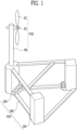
- FIG. 1 is a view for describing a floating offshore power generation apparatus having a floating offshore structure according to one embodiment of the present invention.
- a floating offshore power generation apparatus may include a floating offshore structure FOS and a power generation structure PGS.
- the floating offshore structure FOS may be a structure for supporting the power generation structure PGS.
- the floating offshore structure FOS may include a plurality of columns 100, a plurality of pontoons 200, and a plurality of braces 300.
- the plurality of columns 100 are vertical structures of the floating offshore structure FOS
- the plurality of pontoons 200 may be buoyancy bodies for providing buoyancy to the floating offshore structure FOS
- the plurality of braces 300 may connect the plurality of columns 100 and the plurality of pontoons 200, thereby improving the structural stability of the floating offshore structure FOS.
- the power generation structure PGS may be installed on the floating offshore structure FOS.
- the power generation structure PGS may include a tower TW, a nacelle NC, and a blade BL.
- the tower TW may be installed on the floating offshore structure FOS.
- the tower TW may be installed on one of the plurality of columns 100 of the floating offshore structure FOS.
- the power generation structure PGS may be eccentrically installed on one side of the floating offshore structure FOS.
- the nacelle NC may be installed on an upper portion of the tower TW.
- the nacelle NC may generate electricity using a rotational force of the blade BL.
- the blade BL may be rotatably installed on the nacelle NC and rotated by wind power.
- the power generation structure PGS is eccentrically installed on the one side of the floating offshore structure FOS
- the present invention may not be limited thereto.
- the power generation structure may also be installed on the center of the floating offshore structure FOS.
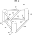
- FIG. 2 is a perspective view for describing the floating offshore structure FOS shown in FIG. 1
- FIG. 3 is a perspective view for describing a first column and a first pontoon of FIG. 2
- FIG. 4 is a perspective view for describing second and third columns and second and third pontoons of FIG. 2 .
- the floating offshore structure FOS may include a plurality of columns 110, 120, and 130, a plurality of pontoons 210, 220, and 230, and a plurality of braces 310, 320, 330, 340, 350, and 360.
- the plurality of columns 110, 120, and 130 may support upper structures, for example, the power generation structure PGS.
- the floating offshore structure FOS may have a polygonal shape by a virtual line connecting the plurality of columns 110, 120, and 130.
- the columns 110, 120, and 130 may be disposed on vertices of polygonal shapes.
- the plurality of columns 110, 120, and 130 may include the first to third columns 110, 120, and 130. Meanwhile, in the embodiment, an example in which the floating offshore structure FOS includes three columns 110, 120, and 130, but the present invention is not limited thereto. For example, the floating offshore structure FOS may also include four or more columns.
- Cross sections of the first to third columns 110, 120, and 130 parallel to a sea level may have a polygonal shape, and the first to third columns 110, 120, and 130 may have the same cross section or different cross sections.
- the cross section parallel to the sea level of the first column 110 may have a hexagonal shape in which regions adjacent to two facing vertices of a rectangle are chamfered.
- the chamfered region of the first column 110 may be disposed toward the outside of the floating offshore structure FOS.
- the chamfered region of the first column 110 may be disposed to face the outside of the polygonal shape formed by the plurality of columns 110, 120, and 130.
- cross sections of the second column 120 and the third column 130 parallel to the sea level may have rectangular shapes.
- a cross-sectional area of the first column 110 parallel to the sea level may be greater than a cross-sectional area parallel to the sea level of each of the second column 120 and the third column 130.
- the cross-sections of the first to third columns 110, 120, and 130 parallel to the sea level have the polygonal shape
- the cross sections of the first to third columns 110, 120, and 130 parallel to the sea level have straight portions in contact with the plurality of pontoons 210, 220, and 230, and the other regions may also have a curved shape.
- the cross sections of the first to third columns 110, 120, and 130 parallel to the sea level have shapes in which a portion of the circle is straightly cut, and the pontoons 210, 220, and 230 are installed in the cut region.
- the plurality of pontoons 210, 220, and 230 may include the first to third pontoons 210, 220, and 230.
- the first to third pontoons 210, 220, and 230 may be installed on lower ends of the first to third columns 110, 120, and 130.
- the first to third pontoons 210, 220, and 230 may be installed inside the polygonal shape formed by the first to third columns 110, 120, and 130.
- the size of the first pontoon 210 may be greater than the sizes of the second pontoon 220 and the third pontoon 230. Therefore, the buoyancy provided by the first pontoon 210 may be greater than the buoyancy provided by each of the second pontoon 220 and the third pontoon 230.
- Cross sections of the first to third pontoons 210, 220, and 230 parallel to the sea level may have a polygonal shape, and the first to third pontoons 210, 220, and 230 may have the same cross section or different cross sections.
- the cross section of the first pontoon 210 parallel to the sea level may have a hexagonal shape in which regions adjacent to two vertices of a rectangle disposed to be spaced apart from the first column 110 are chamfered.
- the cross sections of the second pontoon 220 and the third pontoon 230 may have rectangular shapes in which at least one of the two vertices of the rectangle disposed to be spaced apart from the second column 120 and the third column 130 is chamfered.
- the chamfered regions in the cross sections of the first to third pontoons 210, 220, and 230 may have a straight or rounded curved shape.
- the chamfered regions of the first to third pontoons 210, 220, and 230 may be disposed to face the inside of the polygonal shape formed by the plurality of columns 110, 120, and 130.
- the first to third pontoons 210, 220, and 230 may have hollows 210, 220, and 230.
- the hollow HP is formed in a direction perpendicular to the sea level and can prevent damage to the first to third columns 110, 120, and 130 caused by waves or the like.
- the plurality of braces 310, 320, 330, 340, 350, and 360 may include the upper braces 310, 320, and 330 and the lower braces 340, 350, and 360.
- the upper braces 310, 320, and 330 may include the first to third upper braces 310, 320, and 330.
- the first upper brace 310 may connect an upper end of the first column 110 and an upper end of the second column 120.
- the second upper brace 320 may connect an upper end of the first column 110 and an upper end of the third column 130.
- the third upper brace 330 may connect the first upper brace 310 and the second upper brace 320.
- the third upper brace 330 may connect regions adjacent to the second column 120 and the third column 130 of the first upper brace 310 and the second upper brace 320.
- the lower braces 340, 350, and 360 may include the first lower brace 340 connecting the first pontoon 210 and the second pontoon 220, the second lower brace 350 connecting the first pontoon 210 and the third pontoon 230, and the third lower brace 360 connecting lower portions of the second column 120 and the third column 130.
- the third lower brace 360 may also be connected to the first lower brace 340 and the second lower brace 350.
- a length of the first lower brace 340 may be smaller than a length of the first upper brace 310. This is because the first upper brace 310 connects upper portions of the first column 110 and the second column 120, but the first lower brace 340 connects the first pontoon 210 and the second pontoon 220.
- a length of the second lower brace 350 may be smaller than a length of the second upper brace 320. This is because the second upper brace 320 connects upper portions of the first column 110 and the third column 130, but the second lower brace 350 connects the first pontoon 210 and the third pontoon 230.
- a length of the third lower brace 360 may be greater than a length of the third upper brace 330. This is because the third upper brace 360 connects regions of the first upper brace 310 and the second upper brace 320 adjacent to the second column 120 and the third column 130, but the third lower brace 360 connects the lower portion of the second column 120 and the lower portion of the third column 130.
- the tower of the power generation structure PGS may be installed on the first column 110.
- the power generation structure PGS may be eccentrically installed on one side of the floating offshore structure FOS. This is because the cross-sectional area of the first column 110 is the largest, thereby sufficiently securing an installation space of the power generation structure PGS. In addition, this is because the buoyancy of the first pontoon 210 installed on the first column 110 is the greatest, thereby improving the stability of the power generation structure PGS even when the power generation structure PGS is installed on the first column 110.
- the power generation structure PGS is installed on the first column 110 of the floating offshore structure FOS
- the present invention may not be limited thereto.
- the power generation structure may also be installed on the center of the floating offshore structure FOS.
- the first to third pontoons 210, 220 and 230 may be installed on inner surfaces of lower ends of the first to third columns 110, 120, and 130. Therefore, it may be advantageous for a ship coming alongside the berth to install or maintain the floating offshore structure FOS and the power generation structure PGS.
- first lower brace 340 and the second lower brace 350 is smaller than lengths of the first upper brace 310 and the second upper brace 320, respectively, it is possible to improve the structural stability of the floating offshore structure FOS.
- FIG. 5 is a perspective view for describing a column and a pontoon of a floating offshore structure according to another embodiment of the present invention
- FIG. 6 is a plan view of the columns and pontoons shown in FIG. 5
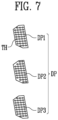
- FIG. 7 is an exploded perspective view for describing a damper shown in FIG. 5 .
- a column 100 is a vertical structure of a floating offshore structure FOS, and a cross section of the column 100 parallel to a sea level may have a polygonal shape.
- a pontoon 200 may provide buoyancy to the floating offshore structure FOS.
- the pontoon 200 may be installed on one side of a lower end of the column 100.
- a cross section of the pontoon 200 parallel to the sea level may have a polygonal shape.
- a cross section of the pontoon 200 parallel to the sea level may have a shape in which regions adjacent to two vertices of a rectangle disposed to be spaced apart from the column 100 are chamfered.
- the pontoon 200 may include a hollow HP, and the hollow HP may be formed in a direction perpendicular to the sea level, thereby preventing damage to the column 100 caused by waves or the like.
- a porous damper DP may be disposed in the hollow HP.
- the damper DP may include at least one porous plate DP1, DP2, and DP3 having a plurality of through holes TH.
- the damper DP may include the first to third porous plates DP 1, DP2, and DP3.
- the damper DP can assist dissipation of the energy of the floating offshore structure FOS. Therefore, the damper DP can reduce the vertical motion of the floating offshore structure FOS.
- the through holes TH of the porous plates DP 1, DP2, and DP3 adjacent to each other may not overlap each other.
- the through holes TH of the first porous plate DP1 and the second porous plate DP2 may not overlap each other.
- the through holes TH of the second porous plate DP2 and the third porous plate DP3 may not overlap each other in a plan view.
- the through holes TH of the first porous plate DP1 and the third porous plate DP3 may also overlap each other in a plan view.
- the through holes TH of the porous plates DP 1, DP2, and DP3 adjacent to each other may also overlap each other.
- the through holes TH of the first to third porous plates DP 1, DP2, and DP3 may overlap each other in a plan view.
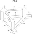
- FIG. 8 is a perspective view for describing a floating offshore structure according to still another embodiment of the present invention
- FIG. 9 is a perspective view for describing the first column shown in FIG. 8 .
- a floating offshore structure FOS may include a plurality of columns 110, 120, and 130, a plurality of pontoons 210, 220, 230, 240, and 250, and a plurality of braces 310 and 320.
- the plurality of columns 110, 120, and 130 may support upper structures, for example, a power generation structure PGS.
- the floating offshore structure FOS may have a polygonal shape by a virtual line connecting the plurality of columns 110, 120, and 130.
- the columns 110, 120, and 130 may be disposed on vertices of polygonal shapes.
- the plurality of columns 110, 120, and 130 may include the first to third columns 110, 120, and 130.
- Cross sections of the first to third columns 110, 120, and 130 parallel to the sea level may have a polygonal shape, and the first to third columns 110, 120, and 130 may have the same cross section or different cross sections.
- a cross section of the first column 110 parallel to the sea level may have a pentagonal shape in which regions adjacent to two facing vertices of a rectangle are chamfered and the chamfered lines are connected.
- Cross sections of the second column 120 and the third column 130 parallel to the sea level may have rectangular shapes.
- the chamfered portion of the first column 110 may be disposed toward the inside of the floating offshore structure FOS.
- a cross-sectional area of the first column 110 may be greater than a cross-sectional area of each of the second column 120 and the third column 130.
- the plurality of pontoons 210, 220, 230, 240, and 250 may include the first to third pontoons 210, 220, and 230, and the first and second extended pontoons 240 and 250.
- the first pontoon 210 may have a shape connecting lower ends of the first column 110 and the second column 120.
- the first pontoon 210 may be connected to one of the chamfered regions of the first column 110.
- the second pontoon 220 may have a shape connecting the first column 110 and the third column 130.
- the second pontoon 220 may be connected to the other of the chamfered regions of the first column 110.
- the third pontoon 230 may have a shape connecting lower ends of the second column 120 and the third column 130.
- the first to third pontoons 210, 220, and 230 may be disposed to correspond to lines of the polygonal shape formed by the first to third columns 110, 120, and 130.
- the first extended pontoon 240 may be installed on an outer surface of the lower end of the second column 120.
- the second extended pontoon 250 may be installed on an outer surface of the lower end of the third column 130.
- the first extended pontoon 240 may have a shape extending parallel to the first pontoon 210
- the second extended pontoon 250 may have a shape extending parallel to the second pontoon 220. Therefore, the first to third pontoons 210, 220, and 230 and the first and second extended pontoons 240 and 250 may form an A shape as a whole.
- the plurality of braces 310 and 320 may include the first brace 310 and the second brace 320.
- the first brace 310 may connect an upper end of the first column 110 and an upper end of the second column 120
- the second brace 320 may connect the upper end of the first column 110 and an upper end of the third column 130.
- the floating offshore structure FOS according to the embodiment may have higher buoyancy than the floating offshore structure in which pontoons are disposed only near the first to third columns 110, 120, and 130. Therefore, it is possible to improve the floating stability of the floating offshore structure FOS.
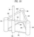
- FIG. 10 is a perspective view for describing a floating offshore structure according to yet another embodiment of the present invention
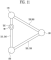
- FIG. 11 is a plan view of the floating offshore structure shown in FIG. 10 .
- a floating offshore structure FOS may include a tower TW, a plurality of columns 160, 170, 180, and TSC, a plurality of braces 310, 320, 330, 340, 350, and 360, and a plurality of horizontal reinforcement parts 410, 420, and 430.
- the plurality of columns 160, 170, 180, and TSC may support upper structures, for example, a power generation structure PGS.
- the plurality of columns 160, 170, 180, and TSC may include the first to third columns 160, 170, and 180 and a tower support column TSC.
- Cross sections of the first to third columns 160, 170, and 180 and the tower support column TSC parallel to a sea level may have various shapes such as a circle or a polygon.
- the cross sections of the first to third columns 160, 170, and 180 and the tower support column TSC parallel to the sea level may have a circular shape.
- the first to third columns 160, 170, and 180 may be disposed outside the tower support column TSC.
- the first to third columns 160, 170, and 180 may be disposed to correspond to vertices of a polygon, for example, a triangle.
- the tower TW, a nacelle NC, and a blade BL of the power generation structure PGS may be installed on the tower support column TSC.
- a height of the tower support column TSC may be greater than or equal to that of each of the first to third columns 160, 170, and 180.
- the plurality of braces 310, 320, 330, 340, 350, and 360 may include the upper braces 310, 320, and 330 and the lower braces 340, 350, and 360.
- the upper braces 310, 320, and 330 may connect upper ends of the first to third columns 160, 170, and 180, respectively.
- the lower braces 340, 350, and 360 may connect lower ends of the first to third columns 160, 170, and 180, respectively.
- the upper braces 310, 320, and 330 may include the first to third upper braces 310, 320, and 330.
- the first upper brace 310 may connect the upper end of the first column 160 and the upper end of the second column 170.
- the second upper brace 320 may connect the upper end of the first column 160 and the upper end of the third column 180.
- the third upper brace 330 may connect the upper end of the second column 170 and the upper end of the third column 180.
- the lower braces 340, 350, and 360 may include the first to third lower braces 340, 350, and 360.
- the first lower brace 340 may connect the lower end of the first column 160 and the lower end of the second column 170.
- the second lower brace 350 may connect the lower end of the first column 160 and the lower end of the third column 180.
- the third lower brace 360 may connect the lower end of the second column 170 and the lower end of the third column 180.
- the tower support column TSC may be provided at one point among sides of the polygon formed by the first to third columns 160, 170, and 180.
- the tower support column TSC may be provided at a point not including the center and end of any one of the sides of the polygon formed by the first to third columns 160, 170, and 180.
- the tower support column TSC may be provided at a position excluding the center and both ends of any one of the sides of the polygon formed by the first to third columns 160, 170, and 180.
- Inner sides of the first to third columns 160, 170, and 180 and the tower support column TSC may be filled with ballast water.
- the tower support column TSC is provided at a position other than the center of the polygon formed by the first to third columns 160, 170, and 180, the amounts of the ballast water filled in the first to third columns 160, 170, and 180 and the tower support column TSC may be different from each other for co-directional wave, current, and wind (COD) control.
- the amount of the filled ballast water may be smaller toward the tower support column TSC.
- the amount of the ballast water filled in the column adjacent to the tower support column TSC among the first to third columns 160, 170, and 180 may be smaller than the amounts of the ballast water filled in the other columns.
- the present invention may encompass all embodiments generated by a combination of two or more of the embodiments or a combination of one or more embodiments and the known technology.
Landscapes
- Engineering & Computer Science (AREA)
- Chemical & Material Sciences (AREA)
- Combustion & Propulsion (AREA)
- Mechanical Engineering (AREA)
- Ocean & Marine Engineering (AREA)
- Physics & Mathematics (AREA)
- Fluid Mechanics (AREA)
- Civil Engineering (AREA)
- Architecture (AREA)
- Structural Engineering (AREA)
- Life Sciences & Earth Sciences (AREA)
- Sustainable Development (AREA)
- Sustainable Energy (AREA)
- General Engineering & Computer Science (AREA)
- Wind Motors (AREA)
- Other Liquid Machine Or Engine Such As Wave Power Use (AREA)
Abstract
Description
- The present invention relates to a floating offshore structure and a floating offshore power generation apparatus having the same.
- As problems such as the environmental regulations due to global warming and the unstable supply and demand of fossil fuels emerge, wind power generation that is one of renewable energy production systems is attracting attention.
- A wind power generation apparatus is an apparatus that is installed on land or the ocean and converts wind energy into electrical energy to produce electric power.
- Wind power apparatuses have been mainly installed on land, but increasingly installed on the ocean. For wind power generation, there is an advantage in that the quality of wind on the ocean is generally better than on land, and an easier response to a wing noise problem may also be possible on the ocean. In particular, in order to secure economic feasibility, the wind power generation apparatus requires to secure large-scale facility, but it is difficult to have the facility on land, and coastal or offshore ocean is emerging as a place for large-scale ocean wind facility.
- A structure for installing the wind power generation apparatus on the ocean may be largely classified into a fixed type and a floating type. The fixed type structure is a type in which the structure is directly fixed to the seabed and responds to the environmental load with structural deformation as on land, and the floating type structure is a type that is floating on the water surface, receives its own weight, buoyancy, environmental load, and a mooring force, and overcomes the environmental load with the motion and mooring force of the structure.
- Until recently, offshore wind power generation apparatuses are fixed types and mainly installed in shallow water. However, the fixed structure is fixed to the seabed and thus provides favorable power generation conditions but when water is deep, the scale of the structure becomes too large and it is difficult to avoid the risk of fatigue failure. In addition, there is a problem in that the cost of manufacturing and installing the structure increases astronomically according to the trend of increasing the size of the wind power generation apparatus.
- In addition, since the wind becomes strong and constant as a distance from the land increases, power generation efficiency can be increased. Therefore, there is a need to develop wind power generation even in deep water away from the coast. Therefore, many studies have been conducted on ocean wind power generation apparatuses using a floating structure not limited by the size of the structure even when the water is deep.
- The present invention has been made in efforts to improve the related art and is directed to providing a floating offshore structure that may be installed regardless of the depth of water and a floating offshore power generation apparatus having the same.
- A floating offshore structure according to one aspect of the present invention includes a plurality of columns and a plurality of pontoons installed on lower ends of the columns, wherein a polygonal shape may be formed by a virtual line connecting the columns, and the pontoons may be installed inside the polygonal shape.
- The columns may include a first column, a second column, and a third column, a cross section of the first column parallel to a sea level may have a hexagonal shape in which regions adjacent to two facing vertices of a rectangle are chamfered, and the chamfered region is disposed to face an outside of the polygonal shape, cross sections of the second and third columns parallel to the sea level may have rectangular shapes, and a cross-sectional area of the first column parallel to the sea level may be greater than a cross-sectional area of each of the second and third columns parallel to the sea level.
- The pontoons may include a first pontoon, a second pontoon, and a third pontoon installed on lower ends of the first to third columns, respectively, and a size of the first pontoon may be greater than a size of each of the second and third pontoons.
- Cross sections of the first to third pontoons parallel to the sea level may have shapes in which a region adjacent to at least one of the two facing vertices of the rectangle is chamfered, and the chamfered region may be disposed to face an inside of the polygonal shape.
- The floating offshore structure may further include upper braces including a first upper brace connecting upper ends of the first column and the second column, a second upper brace connecting upper ends of the first column and the third column, connecting regions of the first upper brace and the second upper brace adjacent to the second column and the third column, and lower braces including a first lower brace connecting a first pontoon and a second pontoon, a second lower brace connecting the first pontoon and a third pontoon, and a third lower brace lower portions of the second column and the third column.
- The pontoons may be installed on inner side surfaces of the polygonal shape of the columns, each of the pontoons may have a hollow formed in a direction perpendicular to a sea level, and a porous damper may be installed in the hollow.
- The porous damper may include a first porous plate, a second porous plate, and a third porous plate each having a plurality of through holes, and the through holes of the first and second porous plates do not overlap each other, and the through holes of the first and third porous plates may overlap each other in a plan view.
- The porous damper may include a first porous plate, a second porous plate, and a third porous plate each having a plurality of through holes, and the through holes of the first to third porous plates may overlap each other in a plan view.
- The columns may include a first column, a second column, and a third column, the pontoons may include a first pontoon, a second pontoon, and a third pontoon connecting lower ends of the first column, the second column, and the third column, and the floating offshore structure may further include a plurality of braces connecting upper ends of the first and second columns and upper ends of the first and third columns and first and second extended pontoons installed on the lower ends of the second and third columns, wherein the first to third pontoons may be disposed to correspond to lines of the polygonal shape, and the first and second extended pontoons may be installed outside the polygonal shape.
- The first extended pontoon may have a shape extending parallel to the first pontoon, and the second extended pontoon may have a shape extending parallel to the first pontoon.
- The floating offshore structure may further include a tower support column configured to support a tower of a power generation structure, wherein the tower support column may be provided at one point of one side of sides of the polygonal shape.
- A floating offshore power generation apparatus may include the above-described floating offshore structure and the power generation structure installed on the floating offshore structure.
- The floating offshore structure and the floating offshore power generation apparatus according to the present invention can be installed without being affected by the depth of water of an installation site.
-
-
FIG. 1 is a view for describing a floating offshore power generation apparatus having a floating offshore structure according to one embodiment of the present invention. -
FIG. 2 is a perspective view for describing the floating offshore structure (FOS) shown inFIG. 1 . -
FIG. 3 is a perspective view for describing a first column and a first pontoon ofFIG. 2 . -
FIG. 4 is a perspective view for describing second and third columns and second and third pontoons ofFIG. 2 . -
FIG. 5 is a perspective view for describing a column and a pontoon of a floating offshore structure according to another embodiment of the present invention. -
FIG. 6 is a plan view of the columns and pontoons shown inFIG. 5 . -
FIG. 7 is an exploded perspective view for describing a damper shown inFIG. 5 . -
FIG. 8 is a perspective view for describing a floating offshore structure according to still another embodiment of the present invention. -
FIG. 9 is a perspective view for describing the first column shown inFIG. 8 . -
FIG. 10 is a perspective view for describing a floating offshore structure according to yet another embodiment of the present invention. -
FIG. 11 is a plan view of the floating offshore structure shown inFIG. 10 . - Objects, specific advantages and new features of the present invention will become more apparent from the following detailed description and exemplary embodiments associated with the accompanying drawings. In the specification, in adding reference numerals to components of each drawing, it should be noted that the same components have the same numbers as possible even when the components are displayed on different drawings. In addition, in describing the present invention, when it is determined that a detailed description of related known technologies may unnecessarily obscure the subject matter of the present invention, the detailed description thereof will be omitted.
- Hereinafter, exemplary embodiments according to the present invention will be described in detail with reference to the accompanying drawings.
-
FIG. 1 is a view for describing a floating offshore power generation apparatus having a floating offshore structure according to one embodiment of the present invention. - Referring to
FIG. 1 , a floating offshore power generation apparatus may include a floating offshore structure FOS and a power generation structure PGS. - The floating offshore structure FOS may be a structure for supporting the power generation structure PGS. The floating offshore structure FOS may include a plurality of
columns 100, a plurality ofpontoons 200, and a plurality ofbraces 300. - The plurality of
columns 100 are vertical structures of the floating offshore structure FOS, the plurality ofpontoons 200 may be buoyancy bodies for providing buoyancy to the floating offshore structure FOS, and the plurality ofbraces 300 may connect the plurality ofcolumns 100 and the plurality ofpontoons 200, thereby improving the structural stability of the floating offshore structure FOS. - The power generation structure PGS may be installed on the floating offshore structure FOS. The power generation structure PGS may include a tower TW, a nacelle NC, and a blade BL.
- The tower TW may be installed on the floating offshore structure FOS. Here, the tower TW may be installed on one of the plurality of
columns 100 of the floating offshore structure FOS. In other words, the power generation structure PGS may be eccentrically installed on one side of the floating offshore structure FOS. - The nacelle NC may be installed on an upper portion of the tower TW. The nacelle NC may generate electricity using a rotational force of the blade BL.
- The blade BL may be rotatably installed on the nacelle NC and rotated by wind power.
- Meanwhile, in one embodiment, an example in which the power generation structure PGS is eccentrically installed on the one side of the floating offshore structure FOS has been described, but the present invention may not be limited thereto. For example, the power generation structure may also be installed on the center of the floating offshore structure FOS.
-
FIG. 2 is a perspective view for describing the floating offshore structure FOS shown inFIG. 1 ,FIG. 3 is a perspective view for describing a first column and a first pontoon ofFIG. 2 , andFIG. 4 is a perspective view for describing second and third columns and second and third pontoons ofFIG. 2 . - Referring to
FIGS. 2 to 4 , the floating offshore structure FOS may include a plurality ofcolumns pontoons braces - The plurality of
columns columns columns - The plurality of
columns third columns columns - Cross sections of the first to
third columns third columns first column 110 may have a hexagonal shape in which regions adjacent to two facing vertices of a rectangle are chamfered. Here, the chamfered region of thefirst column 110 may be disposed toward the outside of the floating offshore structure FOS. The chamfered region of thefirst column 110 may be disposed to face the outside of the polygonal shape formed by the plurality ofcolumns - In addition, the cross sections of the
second column 120 and thethird column 130 parallel to the sea level may have rectangular shapes. A cross-sectional area of thefirst column 110 parallel to the sea level may be greater than a cross-sectional area parallel to the sea level of each of thesecond column 120 and thethird column 130. - Meanwhile, in the embodiment, an example in which the cross-sections of the first to
third columns third columns pontoons third columns pontoons - The plurality of
pontoons third pontoons third pontoons third columns third pontoons third columns - In addition, the size of the
first pontoon 210 may be greater than the sizes of thesecond pontoon 220 and thethird pontoon 230. Therefore, the buoyancy provided by thefirst pontoon 210 may be greater than the buoyancy provided by each of thesecond pontoon 220 and thethird pontoon 230. - Cross sections of the first to
third pontoons third pontoons first pontoon 210 parallel to the sea level may have a hexagonal shape in which regions adjacent to two vertices of a rectangle disposed to be spaced apart from thefirst column 110 are chamfered. In addition, the cross sections of thesecond pontoon 220 and thethird pontoon 230 may have rectangular shapes in which at least one of the two vertices of the rectangle disposed to be spaced apart from thesecond column 120 and thethird column 130 is chamfered. The chamfered regions in the cross sections of the first tothird pontoons - The chamfered regions of the first to
third pontoons columns - The first to
third pontoons hollows third columns - The plurality of
braces upper braces lower braces - The upper braces 310, 320, and 330 may include the first to third
upper braces upper brace 310 may connect an upper end of thefirst column 110 and an upper end of thesecond column 120. The secondupper brace 320 may connect an upper end of thefirst column 110 and an upper end of thethird column 130. The thirdupper brace 330 may connect the firstupper brace 310 and the secondupper brace 320. Here, the thirdupper brace 330 may connect regions adjacent to thesecond column 120 and thethird column 130 of the firstupper brace 310 and the secondupper brace 320. - The lower braces 340, 350, and 360 may include the first
lower brace 340 connecting thefirst pontoon 210 and thesecond pontoon 220, the secondlower brace 350 connecting thefirst pontoon 210 and thethird pontoon 230, and the thirdlower brace 360 connecting lower portions of thesecond column 120 and thethird column 130. The thirdlower brace 360 may also be connected to the firstlower brace 340 and the secondlower brace 350. - A length of the first
lower brace 340 may be smaller than a length of the firstupper brace 310. This is because the firstupper brace 310 connects upper portions of thefirst column 110 and thesecond column 120, but the firstlower brace 340 connects thefirst pontoon 210 and thesecond pontoon 220. - A length of the second
lower brace 350 may be smaller than a length of the secondupper brace 320. This is because the secondupper brace 320 connects upper portions of thefirst column 110 and thethird column 130, but the secondlower brace 350 connects thefirst pontoon 210 and thethird pontoon 230. - A length of the third
lower brace 360 may be greater than a length of the thirdupper brace 330. This is because the thirdupper brace 360 connects regions of the firstupper brace 310 and the secondupper brace 320 adjacent to thesecond column 120 and thethird column 130, but the thirdlower brace 360 connects the lower portion of thesecond column 120 and the lower portion of thethird column 130. - Meanwhile, the tower of the power generation structure PGS may be installed on the
first column 110. In other words, the power generation structure PGS may be eccentrically installed on one side of the floating offshore structure FOS. This is because the cross-sectional area of thefirst column 110 is the largest, thereby sufficiently securing an installation space of the power generation structure PGS. In addition, this is because the buoyancy of thefirst pontoon 210 installed on thefirst column 110 is the greatest, thereby improving the stability of the power generation structure PGS even when the power generation structure PGS is installed on thefirst column 110. - Meanwhile, in one embodiment, an example in which the power generation structure PGS is installed on the
first column 110 of the floating offshore structure FOS has been described, but the present invention may not be limited thereto. For example, the power generation structure may also be installed on the center of the floating offshore structure FOS. - In the above-described floating offshore structure FOS, the first to
third pontoons third columns - In addition, since lengths of the first
lower brace 340 and the secondlower brace 350 is smaller than lengths of the firstupper brace 310 and the secondupper brace 320, respectively, it is possible to improve the structural stability of the floating offshore structure FOS. -
FIG. 5 is a perspective view for describing a column and a pontoon of a floating offshore structure according to another embodiment of the present invention,FIG. 6 is a plan view of the columns and pontoons shown inFIG. 5 , andFIG. 7 is an exploded perspective view for describing a damper shown inFIG. 5 . - Referring to
FIGS. 5 to 7 , acolumn 100 is a vertical structure of a floating offshore structure FOS, and a cross section of thecolumn 100 parallel to a sea level may have a polygonal shape. - A
pontoon 200 may provide buoyancy to the floating offshore structure FOS. Thepontoon 200 may be installed on one side of a lower end of thecolumn 100. - A cross section of the
pontoon 200 parallel to the sea level may have a polygonal shape. For example, a cross section of thepontoon 200 parallel to the sea level may have a shape in which regions adjacent to two vertices of a rectangle disposed to be spaced apart from thecolumn 100 are chamfered. - The
pontoon 200 may include a hollow HP, and the hollow HP may be formed in a direction perpendicular to the sea level, thereby preventing damage to thecolumn 100 caused by waves or the like. In addition, a porous damper DP may be disposed in the hollow HP. The damper DP may include at least one porous plate DP1, DP2, and DP3 having a plurality of through holes TH. For example, the damper DP may include the first to third porous plates DP 1, DP2, and DP3. - The damper DP can assist dissipation of the energy of the floating offshore structure FOS. Therefore, the damper DP can reduce the vertical motion of the floating offshore structure FOS.
- Meanwhile, the through holes TH of the porous plates DP 1, DP2, and DP3 adjacent to each other may not overlap each other. For example, the through holes TH of the first porous plate DP1 and the second porous plate DP2 may not overlap each other. In addition, the through holes TH of the second porous plate DP2 and the third porous plate DP3 may not overlap each other in a plan view. In addition, the through holes TH of the first porous plate DP1 and the third porous plate DP3 may also overlap each other in a plan view.
- In addition, the through holes TH of the porous plates DP 1, DP2, and DP3 adjacent to each other may also overlap each other. For example, the through holes TH of the first to third porous plates DP 1, DP2, and DP3 may overlap each other in a plan view.
-
FIG. 8 is a perspective view for describing a floating offshore structure according to still another embodiment of the present invention, andFIG. 9 is a perspective view for describing the first column shown inFIG. 8 . - Referring to
FIGS. 8 and9 , a floating offshore structure FOS may include a plurality ofcolumns pontoons braces - The plurality of
columns columns columns - The plurality of
columns third columns - Cross sections of the first to
third columns third columns first column 110 parallel to the sea level may have a pentagonal shape in which regions adjacent to two facing vertices of a rectangle are chamfered and the chamfered lines are connected. Cross sections of thesecond column 120 and thethird column 130 parallel to the sea level may have rectangular shapes. Here, the chamfered portion of thefirst column 110 may be disposed toward the inside of the floating offshore structure FOS. In addition, a cross-sectional area of thefirst column 110 may be greater than a cross-sectional area of each of thesecond column 120 and thethird column 130. - The plurality of
pontoons third pontoons extended pontoons first pontoon 210 may have a shape connecting lower ends of thefirst column 110 and thesecond column 120. Here, thefirst pontoon 210 may be connected to one of the chamfered regions of thefirst column 110. Thesecond pontoon 220 may have a shape connecting thefirst column 110 and thethird column 130. Here, thesecond pontoon 220 may be connected to the other of the chamfered regions of thefirst column 110. Thethird pontoon 230 may have a shape connecting lower ends of thesecond column 120 and thethird column 130. In other words, the first tothird pontoons third columns - In the floating offshore structure FOS, the first
extended pontoon 240 may be installed on an outer surface of the lower end of thesecond column 120. In the floating offshore structure FOS, the secondextended pontoon 250 may be installed on an outer surface of the lower end of thethird column 130. Here, the firstextended pontoon 240 may have a shape extending parallel to thefirst pontoon 210, and the secondextended pontoon 250 may have a shape extending parallel to thesecond pontoon 220. Therefore, the first tothird pontoons extended pontoons - The plurality of
braces first brace 310 and thesecond brace 320. Thefirst brace 310 may connect an upper end of thefirst column 110 and an upper end of thesecond column 120, and thesecond brace 320 may connect the upper end of thefirst column 110 and an upper end of thethird column 130. - The floating offshore structure FOS according to the embodiment may have higher buoyancy than the floating offshore structure in which pontoons are disposed only near the first to
third columns -
FIG. 10 is a perspective view for describing a floating offshore structure according to yet another embodiment of the present invention, andFIG. 11 is a plan view of the floating offshore structure shown inFIG. 10 . - Referring to
FIGS. 10 and11 , a floating offshore structure FOS may include a tower TW, a plurality ofcolumns braces - The plurality of
columns columns third columns third columns third columns - The first to
third columns third columns - The tower TW, a nacelle NC, and a blade BL of the power generation structure PGS may be installed on the tower support column TSC. A height of the tower support column TSC may be greater than or equal to that of each of the first to
third columns - The plurality of
braces upper braces lower braces - The upper braces 310, 320, and 330 may connect upper ends of the first to
third columns - The lower braces 340, 350, and 360 may connect lower ends of the first to
third columns - The upper braces 310, 320, and 330 may include the first to third
upper braces upper brace 310 may connect the upper end of thefirst column 160 and the upper end of thesecond column 170. The secondupper brace 320 may connect the upper end of thefirst column 160 and the upper end of thethird column 180. The thirdupper brace 330 may connect the upper end of thesecond column 170 and the upper end of thethird column 180. - The lower braces 340, 350, and 360 may include the first to third
lower braces lower brace 340 may connect the lower end of thefirst column 160 and the lower end of thesecond column 170. The secondlower brace 350 may connect the lower end of thefirst column 160 and the lower end of thethird column 180. The thirdlower brace 360 may connect the lower end of thesecond column 170 and the lower end of thethird column 180. - Meanwhile, the tower support column TSC may be provided at one point among sides of the polygon formed by the first to
third columns third columns third columns - Inner sides of the first to
third columns third columns third columns third columns - In addition to the above-described embodiments, the present invention may encompass all embodiments generated by a combination of two or more of the embodiments or a combination of one or more embodiments and the known technology.
- Although the present invention has been described above in detail through specific embodiments, this is to specifically describe the present invention, the present invention is not limited thereto, and it will be apparent that modifications or improvements thereof are possible by those skilled in the art without departing from the technical spirit of the present invention.
- All simple modifications or changes of the present invention fall within the scope of the present invention, and the specific scope of the present invention will be clarified by the appended claims.
Claims (12)
- A floating offshore structure comprising:a plurality of columns; anda plurality of pontoons installed on lower ends of the columns,wherein a polygonal shape is formed by a virtual line connecting the columns, andthe pontoons are installed inside the polygonal shape.
- The floating offshore structure of claim 1, wherein the columns include a first column, a second column, and a third column,a cross section of the first column parallel to a sea level has a hexagonal shape in which regions adjacent to two facing vertices of a rectangle are chamfered, and the chamfered region is disposed to face an outside of the polygonal shape,cross sections of the second and third columns parallel to the sea level have rectangular shapes, anda cross-sectional area of the first column parallel to the sea level is greater than a cross-sectional area of each of the second and third columns parallel to the sea level.
- The floating offshore structure of claim 2, wherein the pontoons include a first pontoon, a second pontoon, and a third pontoon installed on lower ends of the first to third columns, respectively, and
a size of the first pontoon is greater than a size of each of the second and third pontoons. - The floating offshore structure of claim 3, wherein cross sections of the first to third pontoons parallel to the sea level have shapes in which a region adjacent to at least one of the two facing vertices of the rectangle is chamfered, and the chamfered region is disposed to face an inside of the polygonal shape.
- The floating offshore structure of claim 2, further comprising:upper braces including a first upper brace connecting upper ends of the first column and the second column, a second upper brace connecting upper ends of the first column and the third column, and connecting regions of the first upper brace and the second upper brace adjacent to the second column and the third column; andlower braces including a first lower brace connecting a first pontoon and a second pontoon, a second lower brace connecting the first pontoon and a third pontoon, and a third lower brace lower portions of the second column and the third column.
- The floating offshore structure of claim 1, wherein the pontoons are installed on inner side surfaces of the polygonal shape of the columns,each of the pontoons has a hollow formed in a direction perpendicular to a sea level, anda porous damper is installed in the hollow.
- The floating offshore structure of claim 6, wherein the porous damper includes a first porous plate, a second porous plate, and a third porous plate each having a plurality of through holes, and
the through holes of the first and second porous plates do not overlap each other, and the through holes of the first and third porous plates overlap each other in a plan view. - The floating offshore structure of claim 6, wherein the porous damper includes a first porous plate, a second porous plate, and a third porous plate each having a plurality of through holes, and
the through holes of the first to third porous plates overlap each other in a plan view. - The floating offshore structure of claim 1, wherein the columns include a first column, a second column, and a third column,the pontoons include a first pontoon, a second pontoon, and a third pontoon connecting lower ends of the first column, the second column, and the third column, andthe floating offshore structure further includes a plurality of braces connecting upper ends of the first and second columns and upper ends of the first and third columns, and a first extended pontoon and a second extended pontoon installed on the lower ends of the second and third columns,wherein the first to third pontoons are disposed to correspond to lines of the polygonal shape, andthe first and second extended pontoons are installed outside the polygonal shape.
- The floating offshore structure of claim 9, wherein the first extended pontoon has a shape extending parallel to the first pontoon, and
the second extended pontoon has a shape extending parallel to the first pontoon. - The floating offshore structure of claim 1, further comprising a tower support column configured to support a tower of a power generation structure,
wherein the tower support column is provided at one point of one side of sides of the polygonal shape. - A floating offshore power generation apparatus comprising:the floating offshore structure of any one of claims 1 to 11; anda power generation structure installed on the floating offshore structure.
Applications Claiming Priority (6)
| Application Number | Priority Date | Filing Date | Title |
|---|---|---|---|
| KR20200143771 | 2020-10-30 | ||
| KR1020210095144A KR102558285B1 (en) | 2020-10-30 | 2021-07-20 | Floating offshore structures and floating offshore power plant having the same |
| KR1020210095139A KR102566866B1 (en) | 2020-10-30 | 2021-07-20 | Floating offshore structures and floating offshore power plant having the same |
| KR1020210095134A KR102558282B1 (en) | 2020-10-30 | 2021-07-20 | Floating offshore structures and floating offshore power plant having the same |
| KR1020210139754A KR102623365B1 (en) | 2020-10-30 | 2021-10-19 | Floating offshore structures and floating offshore power plant having the same |
| PCT/KR2021/015242 WO2022092818A1 (en) | 2020-10-30 | 2021-10-27 | Floating offshore structure and floating offshore power generation apparatus having same |
Publications (2)
| Publication Number | Publication Date |
|---|---|
| EP4238862A1 true EP4238862A1 (en) | 2023-09-06 |
| EP4238862A4 EP4238862A4 (en) | 2024-11-06 |
Family
ID=81382865
Family Applications (1)
| Application Number | Title | Priority Date | Filing Date |
|---|---|---|---|
| EP21886812.3A Pending EP4238862A4 (en) | 2020-10-30 | 2021-10-27 | FLOATING OFFSHORE STRUCTURE AND FLOATING OFFSHORE POWER GENERATION DEVICE THEREOF |
Country Status (5)
| Country | Link |
|---|---|
| US (1) | US20230406457A1 (en) |
| EP (1) | EP4238862A4 (en) |
| JP (1) | JP7564358B2 (en) |
| CN (1) | CN116249831A (en) |
| WO (1) | WO2022092818A1 (en) |
Families Citing this family (1)
| Publication number | Priority date | Publication date | Assignee | Title |
|---|---|---|---|---|
| JP7564948B2 (en) * | 2020-10-30 | 2024-10-09 | エイチディー ヒュンダイ ヘビー インダストリーズ カンパニー リミテッド | Floating marine structure and floating marine power generation device equipped with the same |
Family Cites Families (18)
| Publication number | Priority date | Publication date | Assignee | Title |
|---|---|---|---|---|
| JPS6274100U (en) * | 1985-10-30 | 1987-05-12 | ||
| EP1196320B8 (en) * | 1999-07-08 | 2006-04-05 | Deepwater Marine Technology L.L.C. | Extended-base tension leg platform substructure |
| US7900572B2 (en) * | 2008-07-30 | 2011-03-08 | Seahorse Equipment Corporation | Drag-inducing stabilizer plates with damping apertures |
| JP2010280301A (en) * | 2009-06-04 | 2010-12-16 | Shimizu Corp | Floating structure for offshore facilities and construction method of offshore facilities |
| JP2012096601A (en) * | 2010-10-29 | 2012-05-24 | Mitsubishi Heavy Ind Ltd | Oscillation reducing device for floating body |
| FR2970696B1 (en) * | 2011-01-25 | 2013-02-08 | Ideol | ANNULAR FLOATING BODY |
| US9352808B2 (en) * | 2012-01-16 | 2016-05-31 | Seahorse Equipment Corp | Offshore platform having SCR porches mounted on riser keel guide |
| CN102758446B (en) * | 2012-07-30 | 2015-03-18 | 江苏金风科技有限公司 | Semi-submersible type offshore floating wind turbine foundation |
| KR20150100012A (en) * | 2014-02-24 | 2015-09-02 | 대우조선해양 주식회사 | Semi-submersible marine structure |
| CN204110335U (en) * | 2014-05-19 | 2015-01-21 | 中国海洋大学 | Floating-type offshore wind power foundation |
| KR20160007947A (en) * | 2014-07-10 | 2016-01-21 | 현대중공업 주식회사 | Semi-submersible marine structure |
| US11173987B2 (en) * | 2016-10-18 | 2021-11-16 | Atkins Energy, Inc. | Offshore floating structures |
| FR3064976B1 (en) * | 2017-04-11 | 2019-06-21 | Dcns Energies | FLOAT, IN PARTICULAR OFFSHORE WIND. |
| CN107539433A (en) * | 2017-07-03 | 2018-01-05 | 中国船舶工业集团公司第七0八研究所 | A kind of semi-submersible type fan platform |
| KR101956032B1 (en) * | 2018-03-26 | 2019-03-08 | 알렌 주식회사 | Offshore wind power equipment of floating type |
| FR3090567B1 (en) * | 2018-12-24 | 2021-05-21 | Doris Eng | Naval platform supporting a wind turbine and associated naval installation |
| KR102253903B1 (en) * | 2019-02-12 | 2021-05-21 | 에이커 솔루션즈 에이에스 | Wind energy power plant and construction method |
| CN110949633A (en) * | 2019-11-15 | 2020-04-03 | 中国能源建设集团广东省电力设计研究院有限公司 | Barge type floating fan system and floating fan platform |
-
2021
- 2021-10-27 US US18/250,583 patent/US20230406457A1/en active Pending
- 2021-10-27 WO PCT/KR2021/015242 patent/WO2022092818A1/en not_active Ceased
- 2021-10-27 EP EP21886812.3A patent/EP4238862A4/en active Pending
- 2021-10-27 CN CN202180067693.4A patent/CN116249831A/en active Pending
- 2021-10-27 JP JP2023524929A patent/JP7564358B2/en active Active
Also Published As
| Publication number | Publication date |
|---|---|
| WO2022092818A1 (en) | 2022-05-05 |
| US20230406457A1 (en) | 2023-12-21 |
| JP2023547426A (en) | 2023-11-10 |
| CN116249831A (en) | 2023-06-09 |
| EP4238862A4 (en) | 2024-11-06 |
| JP7564358B2 (en) | 2024-10-08 |
Similar Documents
| Publication | Publication Date | Title |
|---|---|---|
| JP4123936B2 (en) | Floating offshore wind power generation facility | |
| KR20250065782A (en) | Floating offshore structures and floating offshore power plant having the same | |
| US20230406457A1 (en) | Floating offshore structure and floating offshore power generation apparatus having same | |
| KR102566866B1 (en) | Floating offshore structures and floating offshore power plant having the same | |
| KR102916471B1 (en) | Floating offshore structures and floating offshore power plant having the same | |
| KR102637606B1 (en) | Floating offshore structures and floating offshore power plant having the same | |
| JP7817341B2 (en) | Floating marine structure and floating marine power generation device equipped with the same | |
| KR102929965B1 (en) | Floating offshore structures and floating offshore power plant having the same |
Legal Events
| Date | Code | Title | Description |
|---|---|---|---|
| STAA | Information on the status of an ep patent application or granted ep patent |
Free format text: STATUS: THE INTERNATIONAL PUBLICATION HAS BEEN MADE |
|
| PUAI | Public reference made under article 153(3) epc to a published international application that has entered the european phase |
Free format text: ORIGINAL CODE: 0009012 |
|
| STAA | Information on the status of an ep patent application or granted ep patent |
Free format text: STATUS: REQUEST FOR EXAMINATION WAS MADE |
|
| 17P | Request for examination filed |
Effective date: 20230330 |
|
| AK | Designated contracting states |
Kind code of ref document: A1 Designated state(s): AL AT BE BG CH CY CZ DE DK EE ES FI FR GB GR HR HU IE IS IT LI LT LU LV MC MK MT NL NO PL PT RO RS SE SI SK SM TR |
|
| DAV | Request for validation of the european patent (deleted) | ||
| DAX | Request for extension of the european patent (deleted) | ||
| A4 | Supplementary search report drawn up and despatched |
Effective date: 20241004 |
|
| RIC1 | Information provided on ipc code assigned before grant |
Ipc: B63B 1/10 20060101ALI20240927BHEP Ipc: F03D 13/25 20160101ALI20240927BHEP Ipc: B63B 35/44 20060101AFI20240927BHEP |