EP4238853A1 - Steer-by-wire steering column for a motor vehicle - Google Patents
Steer-by-wire steering column for a motor vehicle Download PDFInfo
- Publication number
- EP4238853A1 EP4238853A1 EP22159584.6A EP22159584A EP4238853A1 EP 4238853 A1 EP4238853 A1 EP 4238853A1 EP 22159584 A EP22159584 A EP 22159584A EP 4238853 A1 EP4238853 A1 EP 4238853A1
- Authority
- EP
- European Patent Office
- Prior art keywords
- gear
- steering column
- rotation
- steering
- transmission
- Prior art date
- Legal status (The legal status is an assumption and is not a legal conclusion. Google has not performed a legal analysis and makes no representation as to the accuracy of the status listed.)
- Pending
Links
- 230000005540 biological transmission Effects 0.000 claims abstract description 48
- 238000004804 winding Methods 0.000 claims description 56
- 230000007246 mechanism Effects 0.000 description 6
- 230000008901 benefit Effects 0.000 description 4
- 238000006243 chemical reaction Methods 0.000 description 4
- 230000006978 adaptation Effects 0.000 description 2
- 238000011161 development Methods 0.000 description 2
- 230000018109 developmental process Effects 0.000 description 2
- 238000009434 installation Methods 0.000 description 2
- 230000010354 integration Effects 0.000 description 2
- 238000004519 manufacturing process Methods 0.000 description 2
- FYYHWMGAXLPEAU-UHFFFAOYSA-N Magnesium Chemical compound [Mg] FYYHWMGAXLPEAU-UHFFFAOYSA-N 0.000 description 1
- 229910000639 Spring steel Inorganic materials 0.000 description 1
- 229910052782 aluminium Inorganic materials 0.000 description 1
- XAGFODPZIPBFFR-UHFFFAOYSA-N aluminium Chemical compound [Al] XAGFODPZIPBFFR-UHFFFAOYSA-N 0.000 description 1
- 230000000712 assembly Effects 0.000 description 1
- 238000000429 assembly Methods 0.000 description 1
- 238000005266 casting Methods 0.000 description 1
- 230000008878 coupling Effects 0.000 description 1
- 238000010168 coupling process Methods 0.000 description 1
- 238000005859 coupling reaction Methods 0.000 description 1
- 230000001419 dependent effect Effects 0.000 description 1
- 230000009977 dual effect Effects 0.000 description 1
- 229910052749 magnesium Inorganic materials 0.000 description 1
- 239000011777 magnesium Substances 0.000 description 1
- 239000000463 material Substances 0.000 description 1
- 230000009347 mechanical transmission Effects 0.000 description 1
- 229910052751 metal Inorganic materials 0.000 description 1
- 239000002184 metal Substances 0.000 description 1
- 230000009467 reduction Effects 0.000 description 1
- 238000004088 simulation Methods 0.000 description 1
Images


Classifications
-
- B—PERFORMING OPERATIONS; TRANSPORTING
- B62—LAND VEHICLES FOR TRAVELLING OTHERWISE THAN ON RAILS
- B62D—MOTOR VEHICLES; TRAILERS
- B62D5/00—Power-assisted or power-driven steering
- B62D5/001—Mechanical components or aspects of steer-by-wire systems, not otherwise provided for in this maingroup
-
- B—PERFORMING OPERATIONS; TRANSPORTING
- B62—LAND VEHICLES FOR TRAVELLING OTHERWISE THAN ON RAILS
- B62D—MOTOR VEHICLES; TRAILERS
- B62D5/00—Power-assisted or power-driven steering
- B62D5/001—Mechanical components or aspects of steer-by-wire systems, not otherwise provided for in this maingroup
- B62D5/005—Mechanical components or aspects of steer-by-wire systems, not otherwise provided for in this maingroup means for generating torque on steering wheel or input member, e.g. feedback
- B62D5/006—Mechanical components or aspects of steer-by-wire systems, not otherwise provided for in this maingroup means for generating torque on steering wheel or input member, e.g. feedback power actuated
-
- B—PERFORMING OPERATIONS; TRANSPORTING
- B62—LAND VEHICLES FOR TRAVELLING OTHERWISE THAN ON RAILS
- B62D—MOTOR VEHICLES; TRAILERS
- B62D5/00—Power-assisted or power-driven steering
- B62D5/04—Power-assisted or power-driven steering electrical, e.g. using an electric servo-motor connected to, or forming part of, the steering gear
- B62D5/0409—Electric motor acting on the steering column
- B62D5/0412—Electric motor acting on the steering column the axes of motor and steering column being parallel
Definitions
- the invention relates to a steer-by-wire steering column for a motor vehicle which has a steering shaft which is mounted so as to be rotatable about a longitudinal axis relative to a housing and which is operatively connected to a gear, the gear having at least two gear means interacting in the gear mesh.
- the steering shaft is rotatably mounted in the housing of the steering column, which is usually held by a support unit on the vehicle body.
- Steering commands for steering the motor vehicle can be entered by manually rotating the steering wheel attached to the driver's rear end of the steering shaft in order to generate a steering angle of the steerable wheels of the motor vehicle.
- a steer-by-wire steering system While in a conventional steering system the steering shaft is continuously mechanically connected to the steerable wheels via a steering gear, in a steer-by-wire steering system the rotation of the steering shaft is detected by sensors and converted into an electrical control signal for controlling electrical steering actuators, which Adjust the steering angle of the steerable wheels.
- a steer-by-wire steering system the driver does not receive any direct mechanical feedback from the steered wheels via the steering train, which in conventional mechanically coupled steering systems is a reaction or return torque depending on the road surface, vehicle speed, current steering angle and others Operating conditions are reported back to the steering wheel via the steering gear and the mechanically continuous steering shaft.
- the lack of haptic feedback makes it difficult for the driver to reliably grasp current driving situations and carry out appropriate steering maneuvers, which impairs vehicle steerability and thus driving safety.
- a steer-by-wire steering column In order to generate a realistic driving feel, it is known in the prior art for a steer-by-wire steering column to detect parameters such as vehicle speed, steering angle, steering reaction torque and the like from an actual current driving situation or to calculate them in a simulation, and from these to form a feedback signal which is fed into a feedback actuator.
- the feedback actuator has a torque generating device coupled to the steering shaft, for example a drive with an electric motor, the motor shaft of which is coupled to the steering shaft via a transmission.
- the motor can be controlled by a control unit in order to couple a restoring torque (feedback torque) corresponding to the real reaction torque into the steering wheel via the steering shaft.
- feedback torque feedback torque
- Such "force feedback" systems can give the driver the impression of a real driving situation, as with conventional steering, which facilitates an intuitive reaction.
- a rotation limiter for limiting the rotation of the steering shaft relative to the housing is formed integrally with the transmission.
- the steering shaft of the steer-by-wire steering column according to the invention has no mechanical connection to the steerable wheels of a motor vehicle. Accordingly, no means or devices are provided which could convert a rotation of the steering shaft into a steering angle of steerable wheels solely by mechanical transmission.
- a rotation limiter is provided for the first time, which limits the possible angle of rotation of the steering shaft and thus of a steering wheel attached to it to a predetermined maximum value, integrated in a steering column, which is designed to connect a feedback actuator through the gear mechanism interacting with the steering shaft.
- the steering column according to the invention has a feedback actuator. This can advantageously be connected to said transmission or have it.
- Such a feedback actuator can have a drive and/or brake device, which can preferably be structurally combined with the steering column, in other words can be detachably or permanently connected to it.
- the transmission of the steering column according to the invention to have a clutch or another mechanical interface which makes it possible to couple an external torque or an external force into the steering shaft.
- the rotation limiter is integrated into the transmission.
- the rev limiter and the gearbox together form an integrated unit.
- the functions of torque transmission of a feedback torque to the steering shaft and the rotation limitation of the steering shaft, which are implemented in separate assemblies in the prior art, can be combined with one another.
- One advantage is that the design and manufacturing complexity can be reduced.
- Another advantage is that a more compact design with less installation space and reduced weight can be implemented.
- the torque-transmitting properties of the transmission can be used to create a specific angle of rotation limitation.
- a possible angle of rotation of the steering shaft can be realized in a structurally simple manner corresponding to a predetermined transmission or reduction ratio of more than 360°. This also makes it possible to better control the forces occurring to limit the rotary movement in the stop.
- the rotation limiter is designed to directly or indirectly limit a movement of a transmission means that occurs during torque transmission.
- a mechanical stop can preferably be arranged functionally between a gear means and the housing which is fixed relative thereto.
- gear wheels include rotating gear means, such as belt wheels, toothed belt wheels, toothed wheels, or also worms, worm gears or the like.
- the belt or toothed belt circulating as a traction means also represents a circulating transmission means. Because the rotation limiter can interact directly or indirectly with each of the gear wheels to limit its rotation, better structural adaptation than in the prior art is made possible , in which the rotation limiter acts on the steering shaft.
- a transmission means can be connected to the steering shaft in a torque-proof manner.
- a first gear wheel can preferably be mounted on the steering shaft, so that this then itself forms a gear shaft of the transmission. This enables a compact structure.
- a preferred embodiment can be realized in that the transmission is operatively connected to a torque generating device of a feedback actuator.
- the steering column according to the invention can preferably have a feedback actuator. This has at least one torque generating device. This can preferably be connected on the input side to the transmission to which the steering shaft is connected on the output side. This allows a generated by the torque generating device Torque are coupled into the steering shaft, preferably as a feedback moment to simulate a mechanical feedback from steerable wheels.
- the torque generating device can include a motor drive.
- a motor drive may, for example, comprise an electric motor driving a transmission means, such as a gear wheel mounted on the motor shaft.
- another type of torque generating device can also be provided, such as a passive braking device, which can generate a braking torque through friction without an external energy supply, which can counteract a manual steering torque input into the steering shaft.
- An energy accumulator can also be provided, for example a spring accumulator, which can store a torque input manually via the steering wheel and, if necessary, can deliver it back to the steering shaft as a feedback torque.
- the rotation limiter it is possible for the rotation limiter to be designed to be integrated with a gear mechanism.
- the rotation limiter can be connected directly or indirectly to a gear wheel, or also to a traction device or another torque-transmitting transmission device of the transmission.
- a transmission means Due to the integrated design, a transmission means has a dual function, namely for torque transmission and also for limiting rotation. This enables a particularly space-saving integration into the steering column.
- the rotation limiter is designed to be structurally integrated with a gear wheel.
- a gear wheel may include, for example, a pulley or gear mounted on the steering shaft, a drive shaft of a torque generating device such as an engine shaft, or an intermediate shaft. Due to the structural integration, functional elements of the rotation limiter can be attached or formed in or on a gear wheel, such as mechanical stop elements or the like. This enables a particularly compact design, which essentially takes up no more installation space than a transmission of a feedback actuator without a rotation limiter that is known in the prior art.
- a transmission means has a stop element, and the housing has a counter-stop element that interacts with the stop element.
- the stop element moves together with the gear means, for example corresponding to the rotation of a gear wheel.
- the counter-stop element is arranged fixed relative thereto in the path of movement of the stop element, so that it blocks the path of movement.
- the stop element can strike mechanically in the direction of its movement against the counter-stop element, as a result of which, for example, the further rotation of a gear wheel is blocked and thus limited.
- the stop and counter-stop elements can have, for example, axially or radially protruding projections, cams or the like, which protrude with their cross sections into a common relative movement path, so that they can create a positive-locking limitation via a mechanical stop.
- stop and counter-stop elements can be coupled to a gear means via a spindle drive or a stop gear of a different design, so that they can be moved relative to one another and brought into abutment.
- the rotation limiter has a winding core on which a flexible band element can be wound, the winding core being rotatable relative to the housing or a gear mechanism, and the band element being fixed between the winding core and the housing or gear mechanism.
- the flexible band element comprises an elongate band and is flexibly deformable transversely to its longitudinal extension.
- the winding core is rotatable about its winding axis relative to the housing or a gear.
- a first section, for example a first end or a first intermediate section, of the ribbon element is fixed to a periphery of the winding core.
- a second section of the band element, spaced apart from the first section, is fixed to a part of the transmission which is stationary relative to the rotation of the winding core about its winding axis.
- the winding strand which is formed by a strip section of the band element that can be wound onto the winding core, extends as a tight strand between the winding core and the part that is stationary relative thereto.
- the rotation limitation is implemented in that the strip element is wound up on the winding core when the winding core rotates. As a result of the winding, the winding strand between the winding core and the part of the transmission which is stationary relative thereto is shortened. When the maximum possible angle of rotation for limiting the rotation is reached, the strip element is wound up on the winding core to such an extent that it is stretched between the circumferential sections of the winding core and the stationary part that can be rotated relative to one another and subjected to tensile stress. This implements a mechanical end stop and stops the relative rotation of the winding core. An advantage of this design is that a relative rotation of several revolutions can be provided reliably and with little effort. The arrangement can be made compact and practically maintenance-free.
- the winding core can be arranged coaxially with a gear wheel.
- the winding core can be fixed in a rotationally fixed manner, for example, on a gear wheel.
- a first portion of the ribbon member is fixed to a coaxial periphery of the hub.
- a second section of the band element is fixed to the housing, which is fixed relative thereto, so that the winding strand extends between the winding core and the housing.
- the winding core is rotationally fixed relative to the gear wheel with respect to rotation about the winding axis, which is identical to the axis of rotation of the gear wheel, and the belt element extends with its winding strand between the winding core and gear wheel.
- the winding core can be mounted on or in a gear wheel in a space-saving manner, for example within an interior space of a hollow, drum-shaped belt or gear wheel in which the toothing is arranged coaxially on the outside relative to the interior space.
- An advantageous embodiment can provide that the winding core is firmly connected to a gear wheel, for example by a one-piece design. This enables a particularly space-saving design and rational production, for example as a plastic injection-molded part or as a metal die-cast part.
- the winding core is connected to the housing in a rotationally fixed manner, the band element also being wound up to the end stop when the gear wheel rotates relative to it.
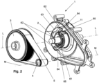
- a transmission 1 in an external view, which is attached to a steering shaft 2, which is rotatably mounted about a longitudinal axis L in a housing of a steer-by-wire steering column, not shown.
- a motor axis M is arranged at a distance. This designates the axis of rotation of a motor shaft, not shown here, of an electric motor of a motor feedback actuator, also not shown here but known in principle. For the explanation of the function according to the invention, it is sufficient that a torque about the motor axis M can be coupled into the transmission 1 and transmitted to the steering shaft 2 by means of a motor or another torque-generating device.
- the transmission 1 has a housing 11 .
- This can have a cast part, for example made of cast aluminum or magnesium, and have fastening means 12 for attachment to the steering column.
- Figures 2 to 6 show a first embodiment of the transmission 1 in different views, the exploded views in the figures 2 , 3 and 4 are pulled apart axially in the direction of the longitudinal axis L, and Figures 5 and 6 show an axial view inside the housing 11 .
- the transmission 1 comprises a belt drive, namely a toothed belt drive, with a first belt wheel 3, which forms a first gear wheel, a second belt wheel 4, which forms a second gear wheel, and a toothed belt 5 running around these belt wheels 3 and 4 as a traction mechanism.
- the belt wheel 3 is fixed in a rotationally fixed manner on the steering shaft 2, and in figures 2 , 3 and 4 shown exploded axially thereof.
- the pulley 4 is connected to a motor shaft, not shown, or a drive shaft of a torque-generating device.
- a rotation limiter 6 which comprises a coaxial winding core 61 connected in a rotationally fixed manner to the belt wheel 3 , retaining elements 62 designed to be stationary on the housing 11 , and a flexible band 63 .
- the tape 63 is designed as a closed tape loop, which is guided radially through the winding core 61 through radial slots 64 .
- Winding strands 65 extend from the winding core 61 up to a section of the band 63 which is wrapped around the holding elements 62 .
- the band 63 with one of the Fixed at a distance from the winding core 61 and connected via the winding strands 65 to the housing 11 .
- figure 3 shows an operating state within the rotation of the steering shaft 2 permitted for steering. This can be freely rotated therein together with the belt wheel 3 and the winding core 61 attached thereto in both directions of rotation, as indicated by the double arrow.
- the winding strands 65 are tension-free.
- the in figure 4 shown limiting or stop state of the rotation limiter 6 is reached.
- the tape 63 is wound onto the winding core 61 to such an extent that the winding strands 65 between the circumference of the winding core 61 and the holding elements 62 of the housing 11 which are fixed relative thereto are subjected to tensile stress.
- they oppose a counterclockwise torque introduced into the steering shaft 2 and block further rotation in this direction of rotation, which is indicated by the crossed-out arrow.
- the rotation limiter 6 is in an end stop.
- the tape 63 can be wound onto the winding core 61 in the reverse winding direction until the winding strands 65 are tensioned in the opposite direction between the winding core 61 and the holding elements 62 . This means that the rotation can be limited in the opposite direction of rotation in the same way.
- the belt wheel 3 can be hollow in the form of a pot or drum, with the winding core 61 being fixed coaxially in the interior space around which the toothed belt 5 runs around the circumference on the outside.
- the peg-shaped holding elements 62 of the housing 11 protrude axially into this interior space of the pulley 3 in such a way that they are positioned on the axial position of the winding core 61 and into the in figure 5 recognizable loop-shaped band 63 engage. This enables the rotation limiter 6 to be compactly integrated into the pulley 3 .
- the holding elements 62 can be integrally formed on the housing 11, for example in a casting process.
- the winding core 62 can be firmly connected to the pulley 3 by means of suitable connecting means, and a one-piece design is also possible.
- a highly flexible material that can withstand tensile loads for example a spring steel strip, can be used for the strip 63 .
- FIG. 7 to 9 a second embodiment of a rotation limiter 6 according to the invention is shown.
- This has axially protruding stop cams 66 and 67 attached to the pulley 3, and corresponding counter-stop cams 68 and 69 that protrude axially in opposite directions from the housing 11.
- stop cams 66 and 67 are moved circumferentially relative to counterstop cams 68 and 69 until they mechanically abut circumferentially thereagainst. This limits the angle of rotation of the pulley 3 relative to the housing.
Abstract
Die vorliegende Erfindung betrifft eine Steer-by-wire-Lenksäule für ein Kraftfahrzeug, die eine relativ zu einem Gehäuse (11) um eine Längsachse (L) drehbar gelagerte Lenkwelle (2) aufweist, die mit einem Getriebe (1) wirkungsmäßig verbunden ist, wobei das Getriebe (1) mindestens zwei im Getriebeeingriff zusammenwirkende Getriebemittel (3, 4) aufweist. Um eine Umdrehungsbegrenzung der Lenkwelle in einer kompakten Bauform mit geringem baulichen Aufwand zu ermöglichen, schlägt die Erfindung vor, dass ein Umdrehungsbegrenzer (6) zur Begrenzung der Rotation der Lenkwelle (2) relativ zum Gehäuse (11) mit dem Getriebe (1) integriert ausgebildet ist.The present invention relates to a steer-by-wire steering column for a motor vehicle, which has a steering shaft (2) which is rotatably mounted relative to a housing (11) about a longitudinal axis (L) and which is operatively connected to a gearbox (1), wherein the transmission (1) has at least two transmission means (3, 4) which interact with the transmission. In order to enable the rotation of the steering shaft to be limited in a compact design with little structural effort, the invention proposes that a rotation limiter (6) for limiting the rotation of the steering shaft (2) relative to the housing (11) is designed to be integrated with the transmission (1). is.
Description
Die Erfindung betrifft eine Steer-by-wire-Lenksäule für ein Kraftfahrzeug, die eine relativ zu einem Gehäuse um eine Längsachse drehbar gelagerte Lenkwelle aufweist, die mit einem Getriebe wirkungsmäßig verbunden ist, wobei das Getriebe mindestens zwei im Getriebeeingriff zusammenwirkende Getriebemittel aufweist.The invention relates to a steer-by-wire steering column for a motor vehicle which has a steering shaft which is mounted so as to be rotatable about a longitudinal axis relative to a housing and which is operatively connected to a gear, the gear having at least two gear means interacting in the gear mesh.
In dem üblicherweise durch eine Trageinheit an der Fahrzeugkarosserie gehaltenen Gehäuse der Lenksäule ist die Lenkwelle drehbar gelagert. Lenkbefehle zur Lenkung des Kraftfahrzeugs können durch manuelle Drehung des am fahrerseitigen, hinteren Ende der Lenkwelle angebrachten Lenkrads eingegeben werden, um einen Lenkeinschlag der lenkbaren Räder des Kraftfahrzeugs zu erzeugen.The steering shaft is rotatably mounted in the housing of the steering column, which is usually held by a support unit on the vehicle body. Steering commands for steering the motor vehicle can be entered by manually rotating the steering wheel attached to the driver's rear end of the steering shaft in order to generate a steering angle of the steerable wheels of the motor vehicle.
Während bei einem konventionellen Lenksystem die Lenkwelle über ein Lenkgetriebe durchgehend mechanisch mit den lenkbaren Rädern verbunden ist, wird in einem Steer-by-wire-Lenksystem die Rotation der Lenkwelle mittels Sensoren erfasst und in ein elektrisches Steuersignal zur Ansteuerung von elektrischen Lenkstellern umgesetzt, die einen Lenkeinschlag der lenkbaren Räder einstellen.While in a conventional steering system the steering shaft is continuously mechanically connected to the steerable wheels via a steering gear, in a steer-by-wire steering system the rotation of the steering shaft is detected by sensors and converted into an electrical control signal for controlling electrical steering actuators, which Adjust the steering angle of the steerable wheels.
Bei einem Steer-by-Wire-Lenksystem erhält der Fahrer von den gelenkten Rädern keine unmittelbare mechanische Rückmeldung über den Lenkstrang, welche bei konventionellen mechanisch gekoppelten Lenkungen als Reaktions- bzw. Rückstellmoment in Abhängigkeit von der Fahrbahnbeschaffenheit, der Fahrzeuggeschwindigkeit, dem aktuellen Lenkwinkel und weiterer Betriebszustände über das Lenkgetriebe und die mechanisch durchgehende Lenkwelle zum Lenkrad zurückgemeldet werden. Die fehlende haptische Rückmeldung erschwert dem Fahrer, aktuelle Fahrsituationen sicher zu erfassen und angemessene Lenkmanöver durchzuführen, wodurch die Fahrzeuglenkbarkeit und damit die Fahrsicherheit beeinträchtigt werden.In a steer-by-wire steering system, the driver does not receive any direct mechanical feedback from the steered wheels via the steering train, which in conventional mechanically coupled steering systems is a reaction or return torque depending on the road surface, vehicle speed, current steering angle and others Operating conditions are reported back to the steering wheel via the steering gear and the mechanically continuous steering shaft. The lack of haptic feedback makes it difficult for the driver to reliably grasp current driving situations and carry out appropriate steering maneuvers, which impairs vehicle steerability and thus driving safety.
Zur Erzeugung eines realistischen Fahrgefühls ist es im Stand der Technik bei einer Steer-by-Wire-Lenksäule bekannt, aus einer tatsächlichen momentanen Fahrsituation Parameter wie Fahrzeuggeschwindigkeit, Lenkwinkel, Lenkungs-Reaktionsmoment und dergleichen zu erfassen oder in einer Simulation zu berechnen, und aus diesen ein Rückkopplungs-Signal zu bilden, welches in einen Feedback-Aktuator eingespeist wird. Der Feedback-Aktuator weist eine mit der Lenkwelle gekuppelte Drehmomenterzeugungseinrichtung auf, beispielsweise einen Antrieb mit einem elektrischen Motor, dessen Motorwelle über ein Getriebe mit der Lenkwelle gekoppelt ist. Der Motor kann von einer Steuereinheit angesteuert werden, um ein dem realen Reaktionsmoment entsprechendes Rückstellmoment (Feedbackmoment) über die Lenkwelle in das Lenkrad einzukoppeln. Derartige "Force-feedback"-Systeme können dem Fahrer den Eindruck einer realen Fahrsituation wie bei einer konventionellen Lenkung geben, was eine intuitive Reaktion erleichtert.In order to generate a realistic driving feel, it is known in the prior art for a steer-by-wire steering column to detect parameters such as vehicle speed, steering angle, steering reaction torque and the like from an actual current driving situation or to calculate them in a simulation, and from these to form a feedback signal which is fed into a feedback actuator. The feedback actuator has a torque generating device coupled to the steering shaft, for example a drive with an electric motor, the motor shaft of which is coupled to the steering shaft via a transmission. The motor can be controlled by a control unit in order to couple a restoring torque (feedback torque) corresponding to the real reaction torque into the steering wheel via the steering shaft. Such "force feedback" systems can give the driver the impression of a real driving situation, as with conventional steering, which facilitates an intuitive reaction.
Bei einer Steer-by-Wire-Lenksäule wird durch die fehlende mechanische Kopplung mit den Rädern die Drehung des Lenkrads nicht durch den Endanschlag der Räder bei Erreichen des maximalen Lenkeinschlags begrenzt. Um dennoch ein zu starkes Einlenken zu vermeiden und auch ein realistisches Lenkgefühl zu simulieren, ist es bekannt, den maximal möglichen Drehwinkel des Lenkrads mittels eines Umdrehungsbegrenzers zu beschränken, der die maximal mögliche Rotation der Lenkwelle beschränkt.With a steer-by-wire steering column, due to the lack of mechanical coupling with the wheels, the rotation of the steering wheel is not limited by the end stop of the wheels when the maximum steering angle is reached. However, in order to avoid turning in too much and also to simulate a realistic steering feel, it is known to limit the maximum possible angle of rotation of the steering wheel by means of a rotation limiter, which limits the maximum possible rotation of the steering shaft.
Im Stand der Technik ist aus der
In der
Angesichts der vorangehend erläuterten Problematik ist es eine Aufgabe der vorliegenden Erfindung, bei einer Steer-by-wire-Lenksäule eine Umdrehungsbegrenzung der Lenkwelle in einer kompakten Bauform mit geringem baulichen Aufwand zu ermöglichen.In view of the problems explained above, it is an object of the present invention to enable rotation limitation of the steering shaft in a steer-by-wire steering column in a compact design with low structural complexity.
Diese Aufgabe wird erfindungsgemäß gelöst durch die Lenksäule mit den Merkmalen des Anspruchs 1. Vorteilhafte Weiterbildungen ergeben sich aus den Unteransprüchen.According to the invention, this object is achieved by the steering column having the features of
Bei einer Steer-by-wire-Lenksäule für ein Kraftfahrzeug, die eine relativ zu einem Gehäuse um eine Längsachse drehbar gelagerte Lenkwelle aufweist, die mit einem Getriebe wirkungsmäßig verbunden ist, wobei das Getriebe mindestens zwei im Getriebeeingriff zusammenwirkende Getriebemittel aufweist, ist erfindungsgemäß vorgesehen, dass ein Umdrehungsbegrenzer zur Begrenzung der Rotation der Lenkwelle relativ zum Gehäuse mit dem Getriebe integriert ausgebildet ist.In the case of a steer-by-wire steering column for a motor vehicle, which has a steering shaft which is mounted so as to be rotatable about a longitudinal axis relative to a housing and which is operatively connected to a gear, the gear having at least two gear means which interact in gear engagement, the invention provides that a rotation limiter for limiting the rotation of the steering shaft relative to the housing is formed integrally with the transmission.
Die Lenkwelle der erfindungsgemäßen Steer-by-wire-Lenksäule weist keine mechanische Verbindung zu lenkbaren Rädern eines Kraftfahrzeugs auf. Entsprechend sind auch keine Mittel oder Vorrichtungen vorgesehen, welche eine Drehung der Lenkwelle allein durch eine mechanische Übertragung in einen Lenkeinschlag lenkbarer Rädern umsetzen könnten.The steering shaft of the steer-by-wire steering column according to the invention has no mechanical connection to the steerable wheels of a motor vehicle. Accordingly, no means or devices are provided which could convert a rotation of the steering shaft into a steering angle of steerable wheels solely by mechanical transmission.
Bei der Erfindung ist erstmals ein Umdrehungsbegrenzer bereitgestellt, der den möglichen Drehwinkel der Lenkwelle und damit eines daran angebrachten Lenkrads, auf einen vorgegebenen Maximalwert beschränkt, in einer Lenksäule integriert, die durch das mit der Lenkwelle zusammenwirkende Getriebe zur Anbindung eines Feedback-Aktuators ausgebildet ist. Dabei kann eine vorteilhafte Ausführung vorsehen, dass die erfindungsgemäße Lenksäule einen Feedback-Aktuator aufweist. Dieser kann in vorteilhafter Weise an das besagte Getriebe angeschlossen sein, oder dieses aufweisen. Ein derartiger Feedback-Aktuator kann eine Antriebs- und/oder Bremseinrichtung aufweisen, die bevorzugt baulich mit der Lenksäule vereinigt sein kann, mit anderen Worten lösbar oder fest mit dieser verbunden sein kann. Es ist auch denkbar und möglich, dass das Getriebe der erfindungsgemäßen Lenksäule eine Kupplung oder eine andere mechanische Schnittstelle aufweist, welche es ermöglicht, ein externes Drehmoment oder eine externe Kraft in die Lenkwelle einzukoppeln.In the invention, a rotation limiter is provided for the first time, which limits the possible angle of rotation of the steering shaft and thus of a steering wheel attached to it to a predetermined maximum value, integrated in a steering column, which is designed to connect a feedback actuator through the gear mechanism interacting with the steering shaft. An advantageous embodiment can provide that the steering column according to the invention has a feedback actuator. This can advantageously be connected to said transmission or have it. Such a feedback actuator can have a drive and/or brake device, which can preferably be structurally combined with the steering column, in other words can be detachably or permanently connected to it. It is also conceivable and possible for the transmission of the steering column according to the invention to have a clutch or another mechanical interface which makes it possible to couple an external torque or an external force into the steering shaft.
Erfindungsgemäß ist der Umdrehungsbegrenzer in das Getriebe integriert. Dadurch bilden der Umdrehungsbegrenzer und das Getriebe zusammen eine integrierte Baueinheit. Die im Stand der Technik in separaten Baugruppen realisierten Funktionen der Drehmomentübertragung eines Feedback-Moments auf die Lenkwelle und der Drehbegrenzung der Lenkwelle können miteinander vereinigt werden. Ein Vorteil ist, dass der konstruktive und fertigungstechnische Aufwand verringert werden kann. Ein weiterer Vorteil ist, dass ein kompakterer Aufbau mit geringerem Bauraumbedarf und reduziertem Gewicht realisierbar ist.According to the invention, the rotation limiter is integrated into the transmission. As a result, the rev limiter and the gearbox together form an integrated unit. The functions of torque transmission of a feedback torque to the steering shaft and the rotation limitation of the steering shaft, which are implemented in separate assemblies in the prior art, can be combined with one another. One advantage is that the design and manufacturing complexity can be reduced. Another advantage is that a more compact design with less installation space and reduced weight can be implemented.
Es ist zusätzlich vorteilhaft, dass die drehmomentübertragenden Eigenschaften des Getriebes genutzt werden können, um eine spezifische Drehwinkelbegrenzung zu erzeugen. Beispielsweise kann entsprechend einem vorgegebenen Übersetzungs- oder Untersetzungsverhältnis konstruktiv einfach ein möglicher Drehwinkel der Lenkwelle realisiert werden, auch von mehr als 360°. Dadurch ist es ebenfalls möglich, die zur Begrenzung der Drehbewegung im Anschlag auftretenden Kräfte besser zu kontrollieren.It is also advantageous that the torque-transmitting properties of the transmission can be used to create a specific angle of rotation limitation. For example, a possible angle of rotation of the steering shaft can be realized in a structurally simple manner corresponding to a predetermined transmission or reduction ratio of more than 360°. This also makes it possible to better control the forces occurring to limit the rotary movement in the stop.
Bevorzugt kann vorgesehen sein, dass der Umdrehungsbegrenzer wirkungsmäßig mit einem Getriebemittel verbunden ist. Der Umdrehungsbegrenzer ist dabei ausgebildet, um eine bei der Drehmomentübertragung auftretende Bewegung eines Getriebemittels direkt oder mittelbar einzuschränken. Hierzu kann bevorzugt ein mechanischer Anschlag wirkungsmäßig zwischen einem Getriebemittel und dem relativ dazu feststehenden Gehäuse angeordnet sein. Wenn die Bewegung des mit dem Umdrehungsbegrenzer verbundenen Getriebemittels im Anschlag gestoppt wird, wird damit ebenfalls die Bewegung sämtlicher in Eingriff stehender Getriebemittel gestoppt, insbesondere auch des mit der Lenkwelle verbundenen Getriebemittels. Ein Vorteil dieser Anordnung ist, dass der Umdrehungsbegrenzer flexibel und mit hoher konstruktiver Freiheit innerhalb des Getriebes angeordnet werden kann, so dass eine optimierte Funktion und Bauraumanpassung erfolgen kann.Provision can preferably be made for the rotation limiter to be operatively connected to a gear mechanism. The rotation limiter is designed to directly or indirectly limit a movement of a transmission means that occurs during torque transmission. For this purpose, a mechanical stop can preferably be arranged functionally between a gear means and the housing which is fixed relative thereto. When the movement of the gear means connected to the rotation limiter is stopped at the stop, the movement of all engaged gear means is also stopped, in particular also the gear means connected to the steering shaft. An advantage of this arrangement is that the rotation limiter can be arranged flexibly and with a high degree of design freedom within the transmission, so that an optimized function and space adaptation can take place.
Eine vorteilhafte Ausführung kann vorsehen, dass das Getriebe mindestens zwei miteinander in Eingriff stehende Getrieberäder aufweist. Getrieberäder umfassen rotierende Getriebemittel, wie beispielsweise Riemenräder, Zahnriemenräder, Zahnräder, oder auch Schnecken, Schneckenräder oder dergleichen. Bei einem Riemen- oder Zahnriementrieb stellt der als Zugmittel umlaufende Riemen oder Zahnriemen ebenfalls ein umlaufendes Getriebemittel dar. Dadurch, dass der Umdrehungsbegrenzer direkt oder mittelbar mit jedem der Getrieberäder zur Begrenzung dessen Drehung zusammenwirken kann, wird eine bessere konstruktive Anpassung als im Stand der Technik ermöglicht, bei dem der Umdrehungsbegrenzer an der Lenkwelle angreift.An advantageous embodiment can provide that the transmission has at least two gear wheels which are in mesh with one another. Gear wheels include rotating gear means, such as belt wheels, toothed belt wheels, toothed wheels, or also worms, worm gears or the like. In the case of a belt or toothed belt drive, the belt or toothed belt circulating as a traction means also represents a circulating transmission means. Because the rotation limiter can interact directly or indirectly with each of the gear wheels to limit its rotation, better structural adaptation than in the prior art is made possible , in which the rotation limiter acts on the steering shaft.
Es kann vorteilhaft sein, dass ein Getriebemittel drehfest mit der Lenkwelle verbunden ist. Bevorzugt kann beispielsweise ein erstes Getrieberad auf der Lenkwelle angebracht sein, so dass diese dann selbst eine Getriebewelle des Getriebes bildet. Dadurch wird ein kompakter Aufbau ermöglicht.It can be advantageous for a transmission means to be connected to the steering shaft in a torque-proof manner. For example, a first gear wheel can preferably be mounted on the steering shaft, so that this then itself forms a gear shaft of the transmission. This enables a compact structure.
Eine bevorzugte Ausführung kann dadurch realisiert sein, dass das Getriebe mit einer Drehmomenterzeugungseinrichtung eines Feedback-Aktuators wirkungsmäßig verbunden ist. Die erfindungsgemäße Lenksäule kann bevorzugt einen Feedback-Aktuator aufweisen. Dieser weist zumindest eine Drehmomenterzeugungseinrichtung auf. Diese kann bevorzugt eingangsseitig an dem Getriebe angeschlossen sein, an dem die Lenkwelle ausgangsseitig angeschlossen ist. Dadurch kann ein von der Drehmomenterzeugungseinrichtung erzeugtes Drehmoment in die Lenkwelle eingekoppelt werden, bevorzugt als Feedback-Moment zur Simulation einer mechanischen Rückmeldung von lenkbaren Rädern.A preferred embodiment can be realized in that the transmission is operatively connected to a torque generating device of a feedback actuator. The steering column according to the invention can preferably have a feedback actuator. This has at least one torque generating device. This can preferably be connected on the input side to the transmission to which the steering shaft is connected on the output side. This allows a generated by the torque generating device Torque are coupled into the steering shaft, preferably as a feedback moment to simulate a mechanical feedback from steerable wheels.
Die Drehmomenterzeugungseinrichtung kann einen motorischen Antrieb umfassen. Ein derartiger aktiver Antrieb kann beispielsweise einen elektrischen Motor aufweisen, der ein Getriebemittel antreibt, wie etwa ein auf der Motorwelle angebrachtes Getrieberad.The torque generating device can include a motor drive. Such an active drive may, for example, comprise an electric motor driving a transmission means, such as a gear wheel mounted on the motor shaft.
Alternativ oder zusätzlich kann auch eine andere Art von Drehmomenterzeugungseinrichtung vorgesehen sein, wie beispielsweise eine passive Bremseinrichtung, die ohne externe Energiezufuhr ein Bremsmoment durch Reibung erzeugen kann, welches einem in die Lenkwelle eingegebenen manuellen Lenkmoment entgegenwirken kann. Es kann auch ein Energiespeicher vorgesehen sein, beispielsweise ein Federspeicher, der ein als manuell über das Lenkrad eingegebenes Drehmoment speichern kann, und bei Bedarf als Feedback-Moment wieder an die Lenkwelle abgeben kann.Alternatively or additionally, another type of torque generating device can also be provided, such as a passive braking device, which can generate a braking torque through friction without an external energy supply, which can counteract a manual steering torque input into the steering shaft. An energy accumulator can also be provided, for example a spring accumulator, which can store a torque input manually via the steering wheel and, if necessary, can deliver it back to the steering shaft as a feedback torque.
In einer vorteilhaften Weiterbildung ist es möglich, dass der Umdrehungsbegrenzer mit einem Getriebemittel integriert ausgebildet ist. Beispielsweise kann der Umdrehungsbegrenzer direkt oder mittelbar mit einem Getrieberad verbunden sein, oder auch mit einem Zugmittel oder einem anderen drehmomentübertragenden Übertragungsmittel des Getriebes. Durch die integrierte Bauweise erhält ein Getriebemittel eine Doppelfunktion, nämlich zur Drehmomentübertragung und auch zur Umdrehungsbegrenzung. Dadurch wird eine besonders bauraumsparende Integration in die Lenksäule ermöglicht.In an advantageous development, it is possible for the rotation limiter to be designed to be integrated with a gear mechanism. For example, the rotation limiter can be connected directly or indirectly to a gear wheel, or also to a traction device or another torque-transmitting transmission device of the transmission. Due to the integrated design, a transmission means has a dual function, namely for torque transmission and also for limiting rotation. This enables a particularly space-saving integration into the steering column.
Bei der vorgenannten Ausführung kann insbesondere vorgesehen sein, dass der Umdrehungsbegrenzer mit einem Getrieberad baulich integriert ausgebildet ist. Ein Getrieberad kann beispielsweise ein Riemenrad oder Zahnrad umfassen, welches auf der Lenkwelle, einer Antriebswelle einer Drehmomenterzeugungseinrichtung, wie einer Motorwelle, oder einer Zwischenwelle angebracht ist. Durch die bauliche Integration können funktionale Elemente des Umdrehungsbegrenzers in oder an einem Getrieberad angebracht oder ausgebildet sein, wie beispielsweise mechanische Anschlagelemente oder dergleichen. Dies ermöglicht eine besonders kompakte Bauweise, die im Wesentlichen nicht mehr Bauraum beansprucht, als ein im Stand der Technik bekanntes Getriebe eines Feedback-Aktuators ohne Umdrehungsbegrenzer.In the aforementioned embodiment, it can be provided in particular that the rotation limiter is designed to be structurally integrated with a gear wheel. A gear wheel may include, for example, a pulley or gear mounted on the steering shaft, a drive shaft of a torque generating device such as an engine shaft, or an intermediate shaft. Due to the structural integration, functional elements of the rotation limiter can be attached or formed in or on a gear wheel, such as mechanical stop elements or the like. This enables a particularly compact design, which essentially takes up no more installation space than a transmission of a feedback actuator without a rotation limiter that is known in the prior art.
Eine vorteilhafte Möglichkeit ist, dass ein Getriebemittel ein Anschlagelement aufweist, und das Gehäuse ein mit dem Anschlagelement zusammenwirkendes Gegenanschlagelement aufweist.An advantageous possibility is that a transmission means has a stop element, and the housing has a counter-stop element that interacts with the stop element.
Das Anschlagelement bewegt sich bei der Drehmomentübertragung zusammen mit dem Getriebemittel, beispielsweise entsprechend der Drehung eines Getrieberads. Das Gegenanschlagelement ist relativ dazu feststehend im Bewegungsweg des Anschlagelements angeordnet, so dass es den Bewegungsweg versperrt. Dadurch kann das Anschlagelement in Richtung seiner Bewegung gegen das Gegenanschlagelement mechanisch anschlagen, wodurch beispielsweise die weitere Drehung eines Getrieberads blockiert wird, und somit begrenzt wird. Die Anschlag- und Gegenanschlagelemente können beispielsweise axial oder radial vorstehende Vorsprünge, Nocken oder dergleichen aufweisen, die mit ihren Querschnitten in eine gemeinsame relative Bewegungsbahn ragen, so dass sie über einen mechanischen Anschlag eine formschlüssige Begrenzung erzeugen können.During torque transmission, the stop element moves together with the gear means, for example corresponding to the rotation of a gear wheel. The counter-stop element is arranged fixed relative thereto in the path of movement of the stop element, so that it blocks the path of movement. As a result, the stop element can strike mechanically in the direction of its movement against the counter-stop element, as a result of which, for example, the further rotation of a gear wheel is blocked and thus limited. The stop and counter-stop elements can have, for example, axially or radially protruding projections, cams or the like, which protrude with their cross sections into a common relative movement path, so that they can create a positive-locking limitation via a mechanical stop.
Es ist auch möglich, dass Anschlag- und Gegenanschlagelemente über einen Spindeltrieb oder ein anders aufgebautes Anschlaggetriebe an ein Getriebemittel angekoppelt sind, so dass sie relativ zueinander bewegt und in Anschlag gebracht werden können.It is also possible for the stop and counter-stop elements to be coupled to a gear means via a spindle drive or a stop gear of a different design, so that they can be moved relative to one another and brought into abutment.
Eine bevorzugte Ausführung kann vorsehen, dass der Umdrehungsbegrenzer einen Wickelkern aufweist, auf dem ein flexibles Bandelement aufwickelbar ist, wobei der Wickelkern relativ zum Gehäuse oder einem Getriebemittel drehbar ist, und das Bandelement zwischen dem Wickelkern und dem Gehäuse oder Getriebemittel fixiert ist. Das flexible Bandelement umfasst ein langgestrecktes Band und ist quer zu seiner Längserstreckung flexibel verformbar. Der Wickelkern ist um seine Wickelachse relativ zum Gehäuse oder einem Getriebemittel drehbar. Ein erster Abschnitt, beispielsweise ein erstes Ende oder ein erster Zwischenabschnitt des Bandelements ist an einem Umfang des Wickelkerns fixiert. Ein von dem ersten Abschnitt beabstandeter zweiter Abschnitt des Bandelements ist an einem relativ zur Drehung des Wickelkerns um seine Wickelachse feststehenden Teil des Getriebes fixiert. Dadurch erstreckt sich der Wickeltrum, der durch einen auf dem Wickelkern aufwickelbaren Bandabschnitt des Bandelements gebildet wird, und zwar als Zugtrum zwischen dem Wickelkern und dem relativ dazu feststehenden Teil.A preferred embodiment can provide that the rotation limiter has a winding core on which a flexible band element can be wound, the winding core being rotatable relative to the housing or a gear mechanism, and the band element being fixed between the winding core and the housing or gear mechanism. The flexible band element comprises an elongate band and is flexibly deformable transversely to its longitudinal extension. The winding core is rotatable about its winding axis relative to the housing or a gear. A first section, for example a first end or a first intermediate section, of the ribbon element is fixed to a periphery of the winding core. A second section of the band element, spaced apart from the first section, is fixed to a part of the transmission which is stationary relative to the rotation of the winding core about its winding axis. As a result, the winding strand, which is formed by a strip section of the band element that can be wound onto the winding core, extends as a tight strand between the winding core and the part that is stationary relative thereto.
Die Umdrehungsbegrenzung wird dadurch realisiert, dass bei einer Drehung des Wickelkerns das Bandelement auf dem Wickelkern aufgewickelt wird. Durch das Aufwickeln wird der Wickeltrum zwischen dem Wickelkern und dem relativ dazu feststehenden Teil des Getriebes verkürzt. Beim Erreichen des zur Umdrehungsbegrenzung maximal möglichen Drehwinkels ist das Bandelement auf dem Wickelkern so weit aufgewickelt, dass es zwischen den gegeneinander verdrehbaren Umfangsabschnitten von Wickelkern und feststehendem Teil gespannt und auf Zug beansprucht wird. Dadurch wird ein mechanischer Endanschlag realisiert, und die relative Drehung des Wickelkerns gestoppt. Ein Vorteil dieser Ausführung ist, dass eine relative Drehung um mehrere Umdrehungen zuverlässig und mit geringem Aufwand bereitgestellt werden kann. Dabei kann die Anordnung kompakt und praktisch wartungsfrei ausgestaltet werden.The rotation limitation is implemented in that the strip element is wound up on the winding core when the winding core rotates. As a result of the winding, the winding strand between the winding core and the part of the transmission which is stationary relative thereto is shortened. When the maximum possible angle of rotation for limiting the rotation is reached, the strip element is wound up on the winding core to such an extent that it is stretched between the circumferential sections of the winding core and the stationary part that can be rotated relative to one another and subjected to tensile stress. This implements a mechanical end stop and stops the relative rotation of the winding core. An advantage of this design is that a relative rotation of several revolutions can be provided reliably and with little effort. The arrangement can be made compact and practically maintenance-free.
In der vorgenannten Ausführung ist es möglich, dass der Wickelkern koaxial zu einem Getrieberad angeordnet ist. Der Wickelkern kann beispielsweise an einem Getrieberad drehfest fixiert sein. Ein erster Abschnitt des Bandelements ist an einem koaxialen Umfang des Wickelkerns fixiert. Ein zweiter Abschnitt des Bandelements ist an dem relativ dazu feststehenden Gehäuse fixiert, so dass sich der Wickeltrum zwischen dem Wickelkern und Gehäuse erstreckt. Alternativ kann vorgesehen sein, dass der Wickelkern relativ zum Getrieberad rotatorisch, bezüglich Drehung um die Wickelachse, die identisch ist mit der Drehachse des Getrieberads, feststehend ist, und das Bandelement erstreckt sich mit seinem Wickeltrum zwischen Wickelkern und Getrieberad.In the aforementioned embodiment, it is possible for the winding core to be arranged coaxially with a gear wheel. The winding core can be fixed in a rotationally fixed manner, for example, on a gear wheel. A first portion of the ribbon member is fixed to a coaxial periphery of the hub. A second section of the band element is fixed to the housing, which is fixed relative thereto, so that the winding strand extends between the winding core and the housing. Alternatively, it can be provided that the winding core is rotationally fixed relative to the gear wheel with respect to rotation about the winding axis, which is identical to the axis of rotation of the gear wheel, and the belt element extends with its winding strand between the winding core and gear wheel.
Der Wickelkern kann raumsparend an oder in einem Getrieberad angebracht sein, beispielsweise innerhalb eines Innenraums eines hohlen, trommelförmigen Riemen- oder Zahnrads bei dem die Verzahnung koaxial außen relativ zum Innenraum angeordnet ist.The winding core can be mounted on or in a gear wheel in a space-saving manner, for example within an interior space of a hollow, drum-shaped belt or gear wheel in which the toothing is arranged coaxially on the outside relative to the interior space.
Eine vorteilhafte Ausführung kann vorsehen, dass der Wickelkern fest mit einem Getrieberad verbunden ist, beispielsweise durch eine einstückige Ausbildung. Dadurch wird eine besonders platzsparende Bauweise ermöglicht, und eine rationelle Fertigung, beispielsweise als Kunststoff-Spritzgussteil oder als Metall-Druckgussteil.An advantageous embodiment can provide that the winding core is firmly connected to a gear wheel, for example by a one-piece design. This enables a particularly space-saving design and rational production, for example as a plastic injection-molded part or as a metal die-cast part.
Alternativ kann vorgesehen sein, dass der Wickelkern drehfest mit dem Gehäuse verbunden ist, wobei das Bandelement bei einer relativen Drehung des Getrieberads ebenfalls bis zum Endanschlag aufgewickelt wird.Alternatively, it can be provided that the winding core is connected to the housing in a rotationally fixed manner, the band element also being wound up to the end stop when the gear wheel rotates relative to it.
Vorteilhafte Ausführungsformen der Erfindung werden im Folgenden anhand der Zeichnungen näher erläutert. Im Einzelnen zeigen:
Figur 1- ein erfindungsgemäßes Getriebe in einer schematischen perspektivischen Ansicht,
Figur 2- eine schematisch auseinander gezogene Darstellung des Getriebes gemäß
Figur 1 , Figur 3- eine schematische axiale Ansicht des Getriebes gemäß
Figur 2 innerhalb des zulässigen Umdrehungswegs, Figur 4- eine schematische axiale Ansicht des Getriebes wie in
Figur 3 Figur 5- eine weitere schematisch auseinander gezogene Darstellung des Getriebes gemäß
Figur 2 , Figur 6- eine weitere Darstellung des Getriebes ähnlich
Figur 5 , - Figur 7
- eine zweite Ausführung eines erfindungsgemäßen Getriebes in einer schematischen axialen Ansicht ähnlich
Figur 3 , - Figur 8
- eine schematische perspektivische Ansicht des Gehäuses aus
Figur 7 , - Figur 9
- eine schematische perspektivische Ansicht des Getrieberads aus
Figur 7 .
- figure 1
- a transmission according to the invention in a schematic perspective view,
- figure 2
- a schematic exploded view of the transmission according to FIG
figure 1 , - figure 3
- a schematic axial view of the transmission according to FIG
figure 2 within the permissible path of rotation, - figure 4
- a schematic axial view of the transmission as in
figure 3 at rotation limit, - figure 5
- a further schematic exploded view of the transmission according to FIG
figure 2 , - figure 6
- another representation of the transmission similar
figure 5 , - figure 7
- a second embodiment of a transmission according to the invention in a schematic axial view similar
figure 3 , - figure 8
- a schematic perspective view of the housing
figure 7 , - figure 9
- a schematic perspective view of the gear wheel
figure 7 .
In den verschiedenen Figuren sind gleiche Teile stets mit den gleichen Bezugszeichen versehen und werden daher in der Regel auch jeweils nur einmal benannt bzw. erwähnt.In the various figures, the same parts are always provided with the same reference symbols and are therefore usually named or mentioned only once.
Parallel zur Längsachse L ist mit Abstand eine Motorachse M angeordnet. Diese bezeichnet die Drehachse einer hier nicht dargestellten Motorwelle eines elektrischen Motors eines hier ebenfalls nicht dargestellten, im Prinzip bekannten motorischen Feedback-Aktuators. Für die Erläuterung der erfindungsgemäßen Funktion ist es ausreichend, dass mittels eines Motors oder einer anderen Drehmomenterzeugungseinrichtung ein Drehmoment um die Motorachse M in das Getriebe 1 eingekoppelt und auf die Lenkwelle 2 übertragen werden kann.Parallel to the longitudinal axis L, a motor axis M is arranged at a distance. This designates the axis of rotation of a motor shaft, not shown here, of an electric motor of a motor feedback actuator, also not shown here but known in principle. For the explanation of the function according to the invention, it is sufficient that a torque about the motor axis M can be coupled into the
Das Getriebe 1 weist ein Gehäuse 11 auf. Dieses kann ein Gussteil aufweisen, beispielsweise aus Aluminium- oder Magnesiumguss, und Befestigungsmittel 12 zur Anbringung an der Lenksäule aufweisen.The
Die nachfolgenden
Das Getriebe 1 umfasst einen Riementrieb, nämlich einen Zahnriementrieb, mit einem ersten Riemenrad 3, welches ein erstes Getrieberad bildet, einem zweiten Riemenrad 4, welches ein zweites Getrieberad bildet, und einem als Zugmittel um diese Riemenräder 3 und 4 umlaufenden Zahnriemen 5.The
Das Riemenrad 3 ist drehfest auf der Lenkwelle 2 fixiert, und in
In der Ausführung gemäß der
Durch eine Drehung der Lenkwelle 2 entgegen dem Uhrzeigersinn wird der in
Durch Drehung in umgekehrter Richtung, also in der Ansicht der
Wie in
Die Halteelemente 62 können einstückig an dem Gehäuse 11 angeformt sein, beispielsweise in einem Gussverfahren. Der Wickelkern 62 kann über geeignete Verbindungsmittel fest mit dem Riemenrad 3 verbunden sein, und es ist ebenfalls eine einstückige Ausführung möglich.The holding
Für das Band 63 kann ein hoch flexibles, auf Zug belastbares Material eingesetzt werden, beispielsweise ein Federstahl-Band.A highly flexible material that can withstand tensile loads, for example a spring steel strip, can be used for the
In den
Bei einer relativen Drehung werden die Anschlagnocken 66 und 67 in Umfangsrichtung relativ zu den Gegenanschlagnocken 68 und 69 bewegt, bis sie in Umfangsrichtung mechanisch dagegen anschlagen. Dadurch wird der Drehwinkel einer Drehung des Riemenrads 3 relativ zum Gehäuse begrenzt.Upon relative rotation, stop
- 11
- Getriebetransmission
- 1111
- GehäuseHousing
- 1212
- Befestigungsmittelfasteners
- 22
- Lenkwellesteering shaft
- 33
- Riemenradpulley
- 44
- Riemenradpulley
- 55
- Zahnriementiming belt
- 66
- Umdrehungsbegrenzerrev limiter
- 6161
- Wickelkernwinding core
- 6262
- Halteelementholding element
- 6363
- Bandtape
- 6464
- Radialschlitzradial slot
- 6565
- Wickeltrumwinding strand
- 66, 6766, 67
- Anschlagnockenstop cam
- 68, 6968, 69
- Gegenanschlagnockencounterstop cam
- LL
- Längsachselongitudinal axis
- MM
- Motorachsemotor axis
Claims (12)
dadurch gekennzeichnet,
dass ein Umdrehungsbegrenzer (6) zur Begrenzung der Rotation der Lenkwelle (2) relativ zum Gehäuse (11) mit dem Getriebe (1) integriert ausgebildet ist.Steer-by-wire steering column for a motor vehicle, which has a steering shaft (2) which is mounted rotatably about a longitudinal axis (L) relative to a housing (11) and is operatively connected to a gear (1), the gear (1 ) has at least two gear means (3, 4) interacting in gear engagement,
characterized,
that a rotation limiter (6) for limiting the rotation of the steering shaft (2) relative to the housing (11) is integrated with the transmission (1).
Priority Applications (1)
| Application Number | Priority Date | Filing Date | Title |
|---|---|---|---|
| EP22159584.6A EP4238853A1 (en) | 2022-03-02 | 2022-03-02 | Steer-by-wire steering column for a motor vehicle |
Applications Claiming Priority (1)
| Application Number | Priority Date | Filing Date | Title |
|---|---|---|---|
| EP22159584.6A EP4238853A1 (en) | 2022-03-02 | 2022-03-02 | Steer-by-wire steering column for a motor vehicle |
Publications (1)
| Publication Number | Publication Date |
|---|---|
| EP4238853A1 true EP4238853A1 (en) | 2023-09-06 |
Family
ID=80623674
Family Applications (1)
| Application Number | Title | Priority Date | Filing Date |
|---|---|---|---|
| EP22159584.6A Pending EP4238853A1 (en) | 2022-03-02 | 2022-03-02 | Steer-by-wire steering column for a motor vehicle |
Country Status (1)
| Country | Link |
|---|---|
| EP (1) | EP4238853A1 (en) |
Citations (6)
| Publication number | Priority date | Publication date | Assignee | Title |
|---|---|---|---|---|
| DE60303081T2 (en) | 2002-02-05 | 2006-07-20 | Delphi Technologies, Inc., Troy | The hand wheel actuator |
| DE102013004055A1 (en) * | 2013-03-08 | 2014-09-11 | Audi Ag | Limiting device for the steering angle input in an electric steering |
| DE102017008651A1 (en) * | 2017-09-14 | 2018-06-07 | Daimler Ag | Variable end stop for a steer-by-wire steering system |
| DE102017206276A1 (en) * | 2017-04-12 | 2018-10-18 | Thyssenkrupp Ag | Steering column for motor vehicles |
| US20190092374A1 (en) * | 2017-09-28 | 2019-03-28 | Dura Operating, Llc | Steering control assembly for a vehicle steer-by-wire system |
| DE102019210096A1 (en) | 2019-07-09 | 2021-01-14 | Thyssenkrupp Ag | Steering column for a motor vehicle |
-
2022
- 2022-03-02 EP EP22159584.6A patent/EP4238853A1/en active Pending
Patent Citations (6)
| Publication number | Priority date | Publication date | Assignee | Title |
|---|---|---|---|---|
| DE60303081T2 (en) | 2002-02-05 | 2006-07-20 | Delphi Technologies, Inc., Troy | The hand wheel actuator |
| DE102013004055A1 (en) * | 2013-03-08 | 2014-09-11 | Audi Ag | Limiting device for the steering angle input in an electric steering |
| DE102017206276A1 (en) * | 2017-04-12 | 2018-10-18 | Thyssenkrupp Ag | Steering column for motor vehicles |
| DE102017008651A1 (en) * | 2017-09-14 | 2018-06-07 | Daimler Ag | Variable end stop for a steer-by-wire steering system |
| US20190092374A1 (en) * | 2017-09-28 | 2019-03-28 | Dura Operating, Llc | Steering control assembly for a vehicle steer-by-wire system |
| DE102019210096A1 (en) | 2019-07-09 | 2021-01-14 | Thyssenkrupp Ag | Steering column for a motor vehicle |
Similar Documents
| Publication | Publication Date | Title |
|---|---|---|
| EP3743324B1 (en) | Steering column for a motor vehicle | |
| EP1934082B1 (en) | Superimposed steering system comprising a mechanical return level | |
| EP2148589B1 (en) | Drive for a movable furniture part | |
| EP1836083B1 (en) | Device for superimposing rotational speeds, comprising a servodrive | |
| DE19541749C1 (en) | Power steering for motor vehicles | |
| DE102013014133B3 (en) | steering stop | |
| EP0981696B1 (en) | Eccentric toothed gear | |
| DE102006045382A1 (en) | Steering system for motor vehicle, has driving authorization system that causes switching of locking device in release condition when driving authorization system detects unauthorized driver | |
| EP3536580A1 (en) | Steering system | |
| EP3681750B1 (en) | Closure device for closing a through-opening in a vehicle body, and vehicle comprising such a closure device | |
| EP3634832B1 (en) | Steering column for a motor vehicle | |
| DE102009055021A1 (en) | Multi-adjustable steering confirmation unit for a motor vehicle with a carrier and a steering column | |
| WO2017182502A1 (en) | Steer-by-wire steering device for motor vehicles | |
| EP2457754A2 (en) | Suspension actuator | |
| EP3853107B1 (en) | Steering column and steer-by-wire steering system | |
| WO2015169556A1 (en) | Steering shaft for a motor vehicle steering system | |
| DE4243267B4 (en) | steering gear | |
| EP0447504B1 (en) | Electric motor servo-steering system | |
| DE4205588C2 (en) | Parking brake system | |
| DE102011121874A1 (en) | Device for stabilizing a steering gear | |
| DE102019204069A1 (en) | Actuator unit for a motor vehicle steering system | |
| EP4238853A1 (en) | Steer-by-wire steering column for a motor vehicle | |
| DE19737380C2 (en) | Cable steering device | |
| WO2005110833A1 (en) | Device for superimposing steering motions on a power steering system as an assistance to steering and process for operating the device | |
| DE102005034185B4 (en) | Device and method for controlling a torque |
Legal Events
| Date | Code | Title | Description |
|---|---|---|---|
| PUAI | Public reference made under article 153(3) epc to a published international application that has entered the european phase |
Free format text: ORIGINAL CODE: 0009012 |
|
| STAA | Information on the status of an ep patent application or granted ep patent |
Free format text: STATUS: THE APPLICATION HAS BEEN PUBLISHED |
|
| AK | Designated contracting states |
Kind code of ref document: A1 Designated state(s): AL AT BE BG CH CY CZ DE DK EE ES FI FR GB GR HR HU IE IS IT LI LT LU LV MC MK MT NL NO PL PT RO RS SE SI SK SM TR |
|
| STAA | Information on the status of an ep patent application or granted ep patent |
Free format text: STATUS: REQUEST FOR EXAMINATION WAS MADE |
|
| 17P | Request for examination filed |
Effective date: 20240306 |
|
| RBV | Designated contracting states (corrected) |
Designated state(s): AL AT BE BG CH CY CZ DE DK EE ES FI FR GB GR HR HU IE IS IT LI LT LU LV MC MK MT NL NO PL PT RO RS SE SI SK SM TR |