EP4238832A1 - Method and apparatus for accessing io devices - Google Patents
Method and apparatus for accessing io devices Download PDFInfo
- Publication number
- EP4238832A1 EP4238832A1 EP20962038.4A EP20962038A EP4238832A1 EP 4238832 A1 EP4238832 A1 EP 4238832A1 EP 20962038 A EP20962038 A EP 20962038A EP 4238832 A1 EP4238832 A1 EP 4238832A1
- Authority
- EP
- European Patent Office
- Prior art keywords
- devices
- various
- access request
- centralized controller
- resource access
- Prior art date
- Legal status (The legal status is an assumption and is not a legal conclusion. Google has not performed a legal analysis and makes no representation as to the accuracy of the status listed.)
- Granted
Links
Images




Classifications
-
- B—PERFORMING OPERATIONS; TRANSPORTING
- B60—VEHICLES IN GENERAL
- B60R—VEHICLES, VEHICLE FITTINGS, OR VEHICLE PARTS, NOT OTHERWISE PROVIDED FOR
- B60R16/00—Electric or fluid circuits specially adapted for vehicles and not otherwise provided for; Arrangement of elements of electric or fluid circuits specially adapted for vehicles and not otherwise provided for
- B60R16/02—Electric or fluid circuits specially adapted for vehicles and not otherwise provided for; Arrangement of elements of electric or fluid circuits specially adapted for vehicles and not otherwise provided for electric constitutive elements
- B60R16/023—Electric or fluid circuits specially adapted for vehicles and not otherwise provided for; Arrangement of elements of electric or fluid circuits specially adapted for vehicles and not otherwise provided for electric constitutive elements for transmission of signals between vehicle parts or subsystems
- B60R16/0231—Circuits relating to the driving or the functioning of the vehicle
-
- G—PHYSICS
- G06—COMPUTING OR CALCULATING; COUNTING
- G06F—ELECTRIC DIGITAL DATA PROCESSING
- G06F9/00—Arrangements for program control, e.g. control units
- G06F9/06—Arrangements for program control, e.g. control units using stored programs, i.e. using an internal store of processing equipment to receive or retain programs
- G06F9/44—Arrangements for executing specific programs
- G06F9/4401—Bootstrapping
- G06F9/4411—Configuring for operating with peripheral devices; Loading of device drivers
-
- H—ELECTRICITY
- H04—ELECTRIC COMMUNICATION TECHNIQUE
- H04L—TRANSMISSION OF DIGITAL INFORMATION, e.g. TELEGRAPHIC COMMUNICATION
- H04L12/00—Data switching networks
- H04L12/28—Data switching networks characterised by path configuration, e.g. LAN [Local Area Networks] or WAN [Wide Area Networks]
- H04L12/40—Bus networks
- H04L12/40006—Architecture of a communication node
- H04L12/40032—Details regarding a bus interface enhancer
-
- G—PHYSICS
- G06—COMPUTING OR CALCULATING; COUNTING
- G06F—ELECTRIC DIGITAL DATA PROCESSING
- G06F9/00—Arrangements for program control, e.g. control units
- G06F9/06—Arrangements for program control, e.g. control units using stored programs, i.e. using an internal store of processing equipment to receive or retain programs
- G06F9/44—Arrangements for executing specific programs
- G06F9/445—Program loading or initiating
- G06F9/44505—Configuring for program initiating, e.g. using registry, configuration files
-
- H—ELECTRICITY
- H04—ELECTRIC COMMUNICATION TECHNIQUE
- H04L—TRANSMISSION OF DIGITAL INFORMATION, e.g. TELEGRAPHIC COMMUNICATION
- H04L12/00—Data switching networks
- H04L12/28—Data switching networks characterised by path configuration, e.g. LAN [Local Area Networks] or WAN [Wide Area Networks]
- H04L12/40—Bus networks
- H04L12/40006—Architecture of a communication node
- H04L12/40013—Details regarding a bus controller
-
- H—ELECTRICITY
- H04—ELECTRIC COMMUNICATION TECHNIQUE
- H04L—TRANSMISSION OF DIGITAL INFORMATION, e.g. TELEGRAPHIC COMMUNICATION
- H04L12/00—Data switching networks
- H04L12/28—Data switching networks characterised by path configuration, e.g. LAN [Local Area Networks] or WAN [Wide Area Networks]
- H04L12/40—Bus networks
- H04L12/40052—High-speed IEEE 1394 serial bus
- H04L12/40078—Bus configuration
-
- B—PERFORMING OPERATIONS; TRANSPORTING
- B60—VEHICLES IN GENERAL
- B60R—VEHICLES, VEHICLE FITTINGS, OR VEHICLE PARTS, NOT OTHERWISE PROVIDED FOR
- B60R16/00—Electric or fluid circuits specially adapted for vehicles and not otherwise provided for; Arrangement of elements of electric or fluid circuits specially adapted for vehicles and not otherwise provided for
- B60R16/02—Electric or fluid circuits specially adapted for vehicles and not otherwise provided for; Arrangement of elements of electric or fluid circuits specially adapted for vehicles and not otherwise provided for electric constitutive elements
- B60R16/023—Electric or fluid circuits specially adapted for vehicles and not otherwise provided for; Arrangement of elements of electric or fluid circuits specially adapted for vehicles and not otherwise provided for electric constitutive elements for transmission of signals between vehicle parts or subsystems
-
- Y—GENERAL TAGGING OF NEW TECHNOLOGICAL DEVELOPMENTS; GENERAL TAGGING OF CROSS-SECTIONAL TECHNOLOGIES SPANNING OVER SEVERAL SECTIONS OF THE IPC; TECHNICAL SUBJECTS COVERED BY FORMER USPC CROSS-REFERENCE ART COLLECTIONS [XRACs] AND DIGESTS
- Y02—TECHNOLOGIES OR APPLICATIONS FOR MITIGATION OR ADAPTATION AGAINST CLIMATE CHANGE
- Y02P—CLIMATE CHANGE MITIGATION TECHNOLOGIES IN THE PRODUCTION OR PROCESSING OF GOODS
- Y02P90/00—Enabling technologies with a potential contribution to greenhouse gas [GHG] emissions mitigation
- Y02P90/02—Total factory control, e.g. smart factories, flexible manufacturing systems [FMS] or integrated manufacturing systems [IMS]
Definitions
- This application relates to the field of communications technologies, and in particular, to an I/O device access method and apparatus.
- I/O devices with input/output (Input/Output, I/O for short) interfaces.
- I/O devices may be various sensors such as a temperature sensor or a humidity sensor, or may be various actuators such as a motor.
- I/O devices have a plurality of types of interfaces, such as a controller area network (controller area network, CAN for short) interface, a local interconnect network (local interconnect network, LIN for short) interface, a pulse width modulation (pulse width modulation, PWM for short) interface, an H-bridge (H-bridge bus, HB for short) interface, an analog-to-digital (analog-to-digital, AD for short) conversion interface, a digital input (digital input, DI for short) interface, and a digital output (digital output, DO for short) interface.
- controller area network controller area network, CAN for short
- local interconnect network local interconnect network, LIN for short
- PWM pulse width modulation
- H-bridge H-bridge bus, HB for short
- AD analog-to-digital
- AD digital input
- DO digital output
- Embodiments of this application provide an I/O device access method and apparatus, to resolve a technical problem that flexibility and reliability are relatively poor when different types of I/O devices are accessed by a centralized controller.
- an embodiment of this application provides an I/O device access method, and the method may include:
- a first centralized controller performs object-oriented modeling on various I/O devices in a vehicle, to generate standard models of the various I/O devices, and generate a mapping configuration file between the various I/O devices and the standard models.
- the first centralized controller generates a resource access request based on an access operation of a user, where the resource access request includes a first standard model of a first I/O device accessed by the user.
- the first centralized controller sends the resource access request to the first I/O device based on the mapping configuration file.
- Object-oriented modeling is performed on the various I/O devices, so that a single standard model can be mapped to a plurality of I/O devices with different model numbers or different interfaces.
- a centralized controller can send a resource access request for a standard model corresponding to the I/O device, can accurately send the resource access request to the I/O device based on the mapping configuration file to complete access to the I/O device, and does not need to perform adjustment based on different vendors, vehicle models, device model numbers, or interface types. Therefore, flexibility and reliability of accessing the I/O device are greatly improved.
- the first centralized controller performs physical port modeling for the I/O devices based on physical ports of the various I/O devices, and configures a conversion relationship between standardized data used to control the standard model and control data used to control the I/O device.
- Upward modeling enables the application to access the I/O devices by accessing the standard models.
- Downward modeling enables the I/O devices with different interfaces to be mapped to a same physical port, and access to the I/O devices with different types of interfaces can be implemented through the physical port.
- corresponding conversion is performed on standardized data corresponding to a standard model and control data corresponding to a control device.
- An effect of shielding a type of a physical port of an I/O device can be implemented, and an upper-layer application can be kept unchanged during development of different vehicle models. This reduces a development difficulty, improves a reuse degree of application-layer software, and facilitates vehicle research and development and testing.
- a vendor a vehicle model, a model number, or an interface changes, only configuration data needs to be updated. This is convenient for upgrade.
- the resource access request further includes first standardized data used to control the first standard model; and the method further includes: The first centralized controller converts, based on the conversion relationship, the first standardized data into first control data corresponding to the first I/O device.
- the first centralized controller sends the first control data to the first I/O device.
- Data conversion is performed.
- I/O devices of different vendors in vehicles with different vehicle models, or with different model numbers or different interfaces are accessed, only a conversion relationship between data needs to be adaptively configured.
- the method further includes: The first centralized controller receives sampled data reported by the first I/O device.
- the first centralized controller converts, based on the conversion relationship, the sampled data into second standardized data corresponding to the first standard model.
- the resource access request when the first centralized controller needs to access a second I/O device controlled by a second centralized controller, the resource access request includes a second standard model of the second I/O device accessed by the user, and the method further includes: The first centralized controller sends the resource access request to the second I/O device through a communication-layer link between the first centralized controller and the second centralized controller.
- an application layer of the second centralized controller does not need to be modified, and a new communications interface does not need to be added. This improves cross-node access efficiency and reduces cross-node access costs.
- an I/O device access apparatus may include:
- the processing unit is specifically configured to:
- the resource access request further includes first standardized data used to control the first standard model.
- the processing unit is further configured to: convert, based on the conversion relationship, the first standardized data into first control data corresponding to the first I/O device.
- the transceiver unit is further configured to send the first control data to the first I/O device.
- the transceiver unit is further configured to: receive sampled data reported by the first I/O device.
- the processing unit is further configured to convert, based on the conversion relationship, the sampled data into second standardized data corresponding to the first standard model.
- the resource access request when the apparatus needs to access a second I/O device controlled by a second centralized controller, the resource access request includes a second standard model of the second I/O device accessed by the user, and the transceiver unit is further configured to: send the resource access request to the second I/O device through a communication-layer link between the first centralized controller and the second centralized controller.
- an I/O device access apparatus including:
- the device abstraction layer is further configured to send the resource access request to a communication layer.
- the communication layer is configured to send a control command to a driver layer based on the resource access request by using a transceiver, to perform an input/output operation on the I/O device.
- the driver layer is configured to send, in response to the control command, sampled data obtained through the input/output operation to the communication layer.
- the communication layer is further configured to send the sampled data to the device abstraction layer
- the device abstraction layer is further configured to convert the sampled data into standardized data corresponding to the standard model, and send the standardized data to the application layer.
- a computer-readable storage medium is provided, and is configured to store a computer program.
- the computer program includes instructions used to perform the method in any one of the first aspect or the possible implementations of the first aspect.
- a computer program product includes computer program code.
- the computer program code When the computer program code is run on a computer, the computer is enabled to perform the method according to any one of the first aspect or the possible implementations of the first aspect.
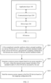
- FIG. 1 is a schematic diagram of an existing software architecture for accessing an I/O device.
- the software architecture includes an application layer, a communication layer (com layer), and a driver layer.
- the application layer 100 is configured to store program code and run a related application for accessing an I/O device.
- the applications may be some control applications for controlling an I/O device in a vehicle, or may be some applications for testing.
- the application layer may send a resource access request to the communication layer
- the communication layer 200 is configured to send the resource access request sent by the application layer to the driver layer by using a transceiver.
- the driver layer 300 is configured to drive the related I/O device.
- the embodiments of this application provide an I/O device access method and apparatus, to improve flexibility and reliability of accessing and controlling an I/O device.
- the following describes in detail the I/O device access method and apparatus provided in the embodiments of this application with reference to FIG. 2 to FIG. 9 .
- FIG. 2 is a schematic flowchart of an I/O device access method according to an embodiment of this application. The method includes the following steps:
- a first centralized controller performs object-oriented modeling on various I/O devices in a vehicle, to generate standard models of the various I/O devices, and generate a mapping configuration file between the various I/O devices and the standard models.
- the various I/O devices in the vehicle may include various parts that can be accessed or controlled in the vehicle, such as a wiper, a window, a light, a seat, a door, a sunroof, and a trunk, and may further include various sensors, such as a distance sensor, a temperature sensor, a light sensor, a gravity sensor, and an acceleration sensor.
- the I/O device may be another electronic control unit (electronic control unit, ECU for short) similar to the first centralized controller.
- ECU electronic control unit
- I/O devices with different interfaces or model numbers may be used.
- adaptation needs to be performed based on different vendors, vehicle models, device model numbers, and interface types.
- object-oriented modeling may be performed on the various I/O devices, for example, on a wiper.
- a wiper of any vendor When an application needs to access or control a wiper of any vendor, on a vehicle with any vehicle model, or with any model number or interface type, a resource access request can be made for such a standardized and object-oriented model of the "wiper".
- S202 Generate a resource access request based on an access operation of a user, where the resource access request includes a first standard model of a first I/O device accessed by the user.
- S203 Send the resource access request to the first I/O device based on the mapping configuration file.
- the centralized controller generates the mapping configuration file between the various I/O devices and the standard models, so that the application can accurately deliver the resource access request to an I/O device that needs to be accessed or controlled to complete access or control.
- obj ect-oriented modeling is performed on the various I/O devices, so that a single standard model can be mapped to a plurality of I/O devices with different model numbers or different interfaces.
- a centralized controller can send a resource access request for a standard model corresponding to the I/O device, can accurately send the resource access request to the I/O device based on the mapping configuration file to complete access to the I/O device, and does not need to perform adjustment based on different vendors, vehicle models, device model numbers, or interface types. Therefore, flexibility and reliability of accessing the I/O device are greatly improved.
- FIG. 3 is a schematic diagram of a software architecture for accessing an I/O device according to an embodiment of this application.
- the software architecture includes:
- the device abstraction layer 10 is further configured to send the resource access request to a communication layer 30.
- the communication layer 30 is configured to send a control command to a driver layer 40 based on the resource access request by using a transceiver, to perform an input/output operation on the I/O device.
- the driver layer 40 is configured to: receive the resource access request forwarded by the transceiver, drive the I/O device, and complete the input/output operation.
- FIG. 4 is a schematic diagram of I/O device modeling and physical port modeling according to an embodiment of this application.
- a device abstraction layer may include a device abstraction module 11 and a port abstraction module 12.
- the device abstraction module 11 may perform object-oriented modeling on various I/O devices in a vehicle for an application such as vehicle control unit (vehicle control unit, VCU for short) software or body control module (body control module, BCM for short) software based on types of the various I/O devices accessed by the application, to generate standard models of the various I/O devices. That is, device modeling is performed upward in an entire software architecture.
- the port abstraction module 12 may perform physical port modeling for the I/O devices based on physical ports of the various I/O devices, and configure a conversion relationship between standardized data used to control the standard model and control data used to control the I/O device. That is, port modeling is performed downward in the entire software architecture. After data is converted, the data is forwarded through a forwarding plane. In other words, an I/O interface is converted to an Ethernet interface. Finally, the data is sent to the various I/O devices through the physical ports.
- Upward modeling enables the application to access the I/O devices by accessing the standard models.
- Downward modeling enables the I/O devices with different interfaces to be mapped to a same physical port, and access to the I/O devices with different types of interfaces can be implemented through the physical port.
- corresponding conversion is performed on standardized data corresponding to a standard model and control data corresponding to a control device.
- corresponding conversion may be performed on data delivered by the first centralized controller and data reported by the first I/O device.
- the resource access request further includes first standardized data used to control the first standard model.
- the first centralized controller may convert, based on the conversion relationship, the first standardized data into first control data corresponding to the first I/O device; and send the first control data to the first I/O device.
- the first centralized controller may receive sampled data reported by the first I/O device, and convert, based on the conversion relationship, the sampled data into second standardized data corresponding to the first standard model.
- a corresponding design tool such as a management application may be used to change a temperature and/or a fitting formula used for an AD calibration configuration, change high and low thresholds and/or a calculation formula used for a PWM configuration, change high and low thresholds, high and low edge configurations and/or a calculation formula used for an output configuration, change a signal offset and/or a calculation formula used for a CAN DBC configuration, and change a switch and/or high and low mapping used for a DI configuration.
- the port abstraction module 12 may perform, based on the completed configurations, calculation according to an AD fitting formula, conversion based on a PWM frequency ratio, DI high and low value mapping, CAN/LIN signal conversion, high-side and low-side driver value mapping, HB constant current value mapping, or SENT bus mapping, to implement data conversion.
- a type of a physical port of an I/O device can be shielded, and an upper-layer application can be kept unchanged during development of different vehicle models. This reduces a development difficulty, improves a reuse degree of application-layer software, and facilitates vehicle research and development and testing.
- a vendor, a vehicle model, a model number, or an interface changes only configuration data needs to be updated. This is convenient for upgrade.
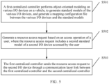
- FIG. 5 is a schematic flowchart of another I/O device access method according to this embodiment of this application. The method includes the following steps:
- a first centralized controller performs object-oriented modeling on various I/O devices in a vehicle, to generate standard models of the various I/O devices, and generate a mapping configuration file between the various I/O devices and the standard models.
- S502 Generate a resource access request based on an access operation of a user, where the resource access request includes a second standard model of a second I/O device accessed by the user.
- the first centralized controller sends the resource access request to the second I/O device through a communication-layer link between the first centralized controller and a second centralized controller.
- FIG. 6 is a schematic diagram of another software architecture for accessing an I/O device according to an embodiment of this application.
- the software architecture includes a first centralized controller and a second centralized controller.
- the first centralized controller includes a device abstraction layer 110, an application layer 120, a communication layer 130, and a driver layer 140
- the second controller includes a communication layer 230 and a driver layer 240.
- the second centralized controller may also include a device abstraction layer 210 and an application layer 220.
- the application layer 220 does not need to be modified, and a new communications interface does not need to be added. This improves cross-node access efficiency and reduces cross-node access costs.
- a specific I/O device access procedure may include local access to an I/O device and cross-node access to an I/O device.
- a local access procedure (the first centralized controller accesses a first I/O device) is as follows:
- the application layer 120 generates a resource access request and sends the resource access request to the device abstraction layer 110.
- the device abstraction layer 110 sends the resource access request to the communication layer 130.
- the device abstraction layer 110 may convert first standardized data in the resource access request into control data corresponding to the first I/O device.
- the communication layer 130 sends a corresponding control command to the driver layer 140 by using a transceiver, to perform an I/O operation on the first I/O device.
- the transceiver herein may be a general-purpose input/output (general-purpose input/output, GPIO for short) transceiver, a CAN transceiver, or the like.
- the driver layer 140 accesses the first I/O device and sends sampled data obtained through the I/O operation to the communication layer 130.
- the communication layer 130 transfers the sampled data to the device abstraction layer 130.
- the device abstraction layer 130 standardizes the access sampled data, that is, converts the sampled data into second standardized data corresponding to a first standard model, and then transfers the second standardized data to the application layer 120.
- a cross-node access procedure (for example, the first centralized controller 1 accesses a second I/O device) is as follows:
- the application layer 120 generates a resource access request and sends the resource access request to the device abstraction layer 110.
- the device abstraction layer 110 sends the resource access request to the communication layer 130.
- the device abstraction layer 110 may convert first standardized data in the resource access request into control data corresponding to the first I/O device.
- the communication layer 130 sends the resource access request to the communication layer 230 of the second centralized controller.
- the communication layer 230 of the second centralized controller sends a corresponding control command to perform an I/O operation on the second I/O device.
- the driver layer 240 of the second centralized controller accesses the second I/O device and transfers sampled data obtained through the I/O operation to the communication layer 230.
- the communication layer 230 of the second centralized controller then transfers the sampled data to the communication layer 130 of the first centralized controller.
- the communication layer 130 transfers the sampled data to the device abstraction layer 130.
- the device abstraction layer 130 standardizes the sampled data, that is, converts the sampled data into standardized data corresponding to a second standard model, and then transfers the standardized data to the application layer 120.
- FIG. 7 is a schematic diagram of a hardware architecture for accessing an I/O device according to an embodiment of this application.
- an I/O device access apparatus includes a first centralized controller and a second centralized controller.
- the two centralized controllers are connected by using the Ethernet (Ethernet, ETH for short).
- the first centralized controller includes a first micro controller unit (micro controller unit, MCU for short) 310, a first micro processing unit (micro processing unit, MPU for short) 320, a first Ethernet switching module (Ethernet switch, LSW for short) 330, and a device abstraction module 340 (the device abstraction module 340 is a function module corresponding to a device abstraction layer, and may be disposed independently, or may be integrated with the first MCU 320 or the first MPU 310).
- the second centralized controller includes a second MPU 410, a second MCU 420, and a second LSW 430 (and may or may not include a device abstraction module 440).
- An I/O device locally accessed by the first centralized controller is a first I/O device 350
- an I/O device locally accessed by the second centralized controller is a second I/O device 450.
- the MCU may be deployed with an application with high real-time performance and a high security level, and may further be responsible for resource access and data forwarding for the I/O device.
- the MPU may be deployed with an application such as an ADAS having a high calculation amount requirement.
- the LSW is used for backbone network communication.
- the first MPU 310 may be deployed with an autonomous driving related application function such as a pre-collision warning function
- the first MCU 320 may be deployed with a VCU function
- the second MPU 410 may be deployed with an advanced driver assistance systems (advanced driver assistance systems, ADAS for short) function
- the second MCU 420 may be deployed with a battery management system (battery management system, BMS) function.
- BMS battery management system
- data of the first I/O device 350 may be transferred to the first MPU 310/first MCU 320, or may be transferred to the second MPU 410/second MCU 420 of the second centralized controller through an Ethernet interface, to implement cross-node access by the second centralized controller to the first I/O device.
- the method in this embodiment may be applied not only to resource access to a vehicle-mounted I/O device, but also to resource access to an industrial I/O device. This is not limited in this embodiment of this application.
- FIG. 8 is a schematic composition diagram of an I/O device access apparatus according to an embodiment of this application.
- the apparatus includes:
- processing unit 1000 is specifically configured to:
- the resource access request further includes first standardized data used to control the first standard model.
- the processing unit 1000 is further configured to: convert, based on the conversion relationship, the first standardized data into first control data corresponding to the first I/O device.
- the transceiver unit 2000 is further configured to send the first control data to the first I/O device.
- the transceiver unit 2000 is further configured to: receive sampled data reported by the first I/O device.
- the processing unit 1000 is further configured to convert, based on the conversion relationship, the sampled data into second standardized data corresponding to the first standard model.
- the resource access request includes a second standard model of the second I/O device accessed by the user
- the transceiver unit 2000 is further configured to: send the resource access request to the second I/O device through a communication-layer link between the first centralized controller and the second centralized controller.
- FIG. 9 is a schematic composition diagram of another I/O device access apparatus according to an embodiment of this application.
- the apparatus may include a processor 1110, a memory 1120, and a transceiver 1130.
- the processor 1110, the memory 1120, and the transceiver 1130 are connected by using a bus 1140.
- the memory 1120 is configured to store instructions.
- the processor 1110 is configured to execute the instructions stored in the memory 1120, to implement steps performed by the first centralized controller in the methods corresponding to FIG. 2 to FIG. 6 .
- the processor 1110 is configured to execute the instructions stored in the memory 120, to control the transceiver 1130 to receive a signal or send a signal and complete the steps performed by the apparatus in the foregoing methods.
- the memory 1120 may be integrated into the processor 1110, or may be disposed independent of the processor 1110.
- a function of the transceiver unit 1130 is implemented by using a transceiver circuit or a dedicated transceiver chip; and it may be considered that the processor 1110 is implemented by using a dedicated processing chip, a processing circuit, a processor, or a general-purpose chip.
- the apparatus provided in this embodiment of this application is implemented by using a general-purpose computer. That is, program code for implementing functions of the processor 1110 and the transceiver 1130 is stored in the memory 1120, and a general-purpose processor implements the functions of the processor 1110 and the transceiver 1130 by executing the code in the memory 1120.
- a computer-readable storage medium stores instructions. The instructions are executed, to perform the method performed by the first centralized controller in the foregoing method embodiments.
- a computer program product including instructions is provided. The instructions are executed, to perform the method performed by the first centralized controller in the foregoing method embodiments.
- FIG. 9 shows only one memory and one processor. In an actual controller, there may be a plurality of processors and memories.
- the memory may also be referred to as a storage medium, a storage device, or the like. This is not limited in this embodiment of this application.
- the processor may be a central processing unit (central processing unit, CPU for short).
- the processor may further be another general-purpose processor, a digital signal processor (digital signal processor, DSP for short), an application-specific integrated circuit (application-specific integrated circuit, ASIC for short), a field-programmable gate array (field-programmable gate array, FPGA for short) or another programmable logic device, a discrete gate or transistor logic device, a discrete hardware component, or the like.
- the memory mentioned in this embodiment of the present invention may be a volatile memory or a nonvolatile memory, or may include a volatile memory and a nonvolatile memory.
- the nonvolatile memory may be a read-only memory (read-only memory, ROM for short), a programmable read-only memory (programmable ROM, PROM for short), an erasable programmable read-only memory (erasable PROM, EPROM for short), an electrically erasable programmable read-only memory (electrically EPROM, EEPROM for short), or a flash memory.
- the volatile memory may be a random access memory (random access memory, RAM for short) and is used as an external cache.
- RAMs may be used, for example, a static random access memory (static RAM, SRAM for short), a dynamic random access memory (dynamic RAM, DRAM for short), a synchronous dynamic random access memory (synchronous DRAM, SDRAM for short), a double data rate synchronous dynamic random access memory (double data rate SDRAM, DDR SDRAM for short), an enhanced synchronous dynamic random access memory (enhanced SDRAM, ESDRAM for short), a synchlink dynamic random access memory (synchlink DRAM, SLDRAM for short), and a direct rambus random access memory (direct rambus RAM, DR RAM for short).
- static random access memory static random access memory
- dynamic RAM dynamic random access memory
- DRAM synchronous dynamic random access memory
- double data rate SDRAM double data rate SDRAM
- ESDRAM enhanced synchronous dynamic random access memory
- synchlink dynamic random access memory synchlink dynamic random access memory
- direct rambus RAM direct rambus RAM, DR RAM for short
- the processor is a general-purpose processor, a DSP, an ASIC, an FPGA or another programmable logic device, a discrete gate or transistor logic device, or a discrete hardware component
- the memory storage module
- the memory described in this specification aims to include but is not limited to these memories and any memory of another appropriate type.
- the bus may further include a power bus, a control bus, a status signal bus, and the like, in addition to a data bus.
- a power bus may further include a power bus, a control bus, a status signal bus, and the like, in addition to a data bus.
- various buses in this figure are marked as the bus.
- steps in the foregoing methods may be implemented by using an integrated logical circuit of hardware in the processor, or by using instructions in a form of software.
- the steps of the method disclosed with reference to the embodiments of this application may be directly performed by a hardware processor, or may be performed by using a combination of hardware in the processor and a software module.
- the software module may be located in a mature storage medium in the art, such as a random access memory, a flash memory, a read-only memory, a programmable read-only memory, an electrically erasable programmable memory, a register, or the like.
- the storage medium is located in the memory, and the processor reads information in the memory and completes the steps in the foregoing methods in combination with the hardware in the processor. To avoid repetition, details are not described herein again.
- an embodiment of this application further provides a system.
- the system includes the first centralized controller and the various I/O devices, and may further include the second centralized controller, and the like.
- Sequence numbers of the foregoing processes do not mean execution sequences in the embodiments of this application.
- the execution sequences of the processes should be determined based on functions and internal logic of the processes, and should not be constructed as any limitation on the implementation processes of the embodiments of this application.
- the disclosed system, apparatus, and method may be implemented in other manners.
- the described apparatus embodiment is merely an example.
- division into the units is merely logical function division and may be other division in an actual implementation.
- a plurality of units or components may be combined or integrated into another system, or some features may be ignored or not performed.
- the displayed or discussed mutual couplings or direct couplings or communication connections may be implemented through some interfaces.
- the indirect couplings or communication connections between the apparatuses or units may be implemented in electronic, mechanical, or other forms.
- the units described as separate parts may or may not be physically separate, and parts displayed as units may or may not be physical units, may be located in one position, or may be distributed on a plurality of network units. Some or all of the units may be selected based on actual requirements to achieve the objectives of the solutions in the embodiments.
- function units in the embodiments of this application may be integrated into one processing unit, or each of the units may exist alone physically, or two or more units are integrated into one unit.
- All or some of the foregoing embodiments may be implemented by using software, hardware, firmware, or any combination thereof.
- software is used to implement the embodiments, all or some of the embodiments may be implemented in a form of a computer program product.
- the computer program product includes one or more computer instructions.
- the computer may be a general-purpose computer, a dedicated computer, a computer network, or another programmable apparatus.
- the computer instructions may be stored in a computer-readable storage medium or may be transmitted from a computer-readable storage medium to another computer-readable storage medium.
- the computer instructions may be transmitted from a website, computer, server, or data center to another website, computer, server, or data center in a wired (for example, a coaxial cable, an optical fiber, or a digital subscriber line) or wireless (for example, infrared, radio, or microwave) manner.
- the computer-readable storage medium may be any usable medium accessible by a computer, or a data storage device, for example, a server or a data center, integrating one or more usable media.
- the usable medium may be a magnetic medium (for example, a floppy disk, a hard disk, or a magnetic tape), an optical medium (for example, a DVD), a semiconductor medium (for example, a solid-state drive), or the like.
Landscapes
- Engineering & Computer Science (AREA)
- Software Systems (AREA)
- Theoretical Computer Science (AREA)
- Computer Networks & Wireless Communication (AREA)
- Signal Processing (AREA)
- Physics & Mathematics (AREA)
- General Engineering & Computer Science (AREA)
- General Physics & Mathematics (AREA)
- Automation & Control Theory (AREA)
- Mechanical Engineering (AREA)
- Computer Security & Cryptography (AREA)
- Stored Programmes (AREA)
Abstract
Description
- This application relates to the field of communications technologies, and in particular, to an I/O device access method and apparatus.
- With development of intelligent vehicles and new energy vehicles, automotive electrical and electronic architectures evolve from distribution to centralization, and controllers tend to be centralized. Current vehicles usually have dozens or even hundreds of controllers and hundreds of I/O devices with input/output (Input/Output, I/O for short) interfaces. These I/O devices may be various sensors such as a temperature sensor or a humidity sensor, or may be various actuators such as a motor. These I/O devices have a plurality of types of interfaces, such as a controller area network (controller area network, CAN for short) interface, a local interconnect network (local interconnect network, LIN for short) interface, a pulse width modulation (pulse width modulation, PWM for short) interface, an H-bridge (H-bridge bus, HB for short) interface, an analog-to-digital (analog-to-digital, AD for short) conversion interface, a digital input (digital input, DI for short) interface, and a digital output (digital output, DO for short) interface. When various I/O devices are accessed by a centralized controller, flexibility and reliability are relatively poor
- Embodiments of this application provide an I/O device access method and apparatus, to resolve a technical problem that flexibility and reliability are relatively poor when different types of I/O devices are accessed by a centralized controller.
- According to a first aspect, an embodiment of this application provides an I/O device access method, and the method may include:
- A first centralized controller performs object-oriented modeling on various I/O devices in a vehicle, to generate standard models of the various I/O devices, and generate a mapping configuration file between the various I/O devices and the standard models.
- The first centralized controller generates a resource access request based on an access operation of a user, where the resource access request includes a first standard model of a first I/O device accessed by the user.
- The first centralized controller sends the resource access request to the first I/O device based on the mapping configuration file.
- Object-oriented modeling is performed on the various I/O devices, so that a single standard model can be mapped to a plurality of I/O devices with different model numbers or different interfaces. In addition, when accessing an I/O device, a centralized controller can send a resource access request for a standard model corresponding to the I/O device, can accurately send the resource access request to the I/O device based on the mapping configuration file to complete access to the I/O device, and does not need to perform adjustment based on different vendors, vehicle models, device model numbers, or interface types. Therefore, flexibility and reliability of accessing the I/O device are greatly improved.
- In a possible implementation, that a first centralized controller performs object-oriented modeling on various I/O devices in a vehicle, to generate standard models of the various I/O devices, and generate a mapping configuration file between the various I/O devices and the standard models includes:
The first centralized controller performs object-oriented modeling on the various I/O devices in the vehicle for an application based on types of the various I/O devices accessed by the application, to generate the standard models of the various I/O devices. - The first centralized controller performs physical port modeling for the I/O devices based on physical ports of the various I/O devices, and configures a conversion relationship between standardized data used to control the standard model and control data used to control the I/O device.
- Upward modeling enables the application to access the I/O devices by accessing the standard models. Downward modeling enables the I/O devices with different interfaces to be mapped to a same physical port, and access to the I/O devices with different types of interfaces can be implemented through the physical port. When the I/O devices with different types of interfaces are accessed, corresponding conversion is performed on standardized data corresponding to a standard model and control data corresponding to a control device. An effect of shielding a type of a physical port of an I/O device can be implemented, and an upper-layer application can be kept unchanged during development of different vehicle models. This reduces a development difficulty, improves a reuse degree of application-layer software, and facilitates vehicle research and development and testing. In addition, when a vendor, a vehicle model, a model number, or an interface changes, only configuration data needs to be updated. This is convenient for upgrade.
- In a possible implementation, the resource access request further includes first standardized data used to control the first standard model; and the method further includes:
The first centralized controller converts, based on the conversion relationship, the first standardized data into first control data corresponding to the first I/O device. - The first centralized controller sends the first control data to the first I/O device.
- Data conversion is performed. When I/O devices of different vendors, in vehicles with different vehicle models, or with different model numbers or different interfaces are accessed, only a conversion relationship between data needs to be adaptively configured.
- In a possible implementation, the method further includes:
The first centralized controller receives sampled data reported by the first I/O device. - The first centralized controller converts, based on the conversion relationship, the sampled data into second standardized data corresponding to the first standard model.
- In a possible implementation, when the first centralized controller needs to access a second I/O device controlled by a second centralized controller, the resource access request includes a second standard model of the second I/O device accessed by the user, and the method further includes:
The first centralized controller sends the resource access request to the second I/O device through a communication-layer link between the first centralized controller and the second centralized controller. - In this cross-node access manner, an application layer of the second centralized controller does not need to be modified, and a new communications interface does not need to be added. This improves cross-node access efficiency and reduces cross-node access costs.
- According to a second aspect, an embodiment of this application provides an I/O device access apparatus, and the apparatus may include:
- a processing unit, configured to perform object-oriented modeling on various I/O devices in a vehicle, to generate standard models of the various I/O devices, and generate a mapping configuration file between the various I/O devices and the standard models; and generate a resource access request based on an access operation of a user, where the resource access request includes a first standard model of a first I/O device accessed by the user; and
- a transceiver unit, configured to send the resource access request to the first I/O device based on the mapping configuration file.
- In a possible implementation, the processing unit is specifically configured to:
- perform object-oriented modeling on the various I/O devices in the vehicle for an application based on types of the various I/O devices accessed by the application, to generate the standard models of the various I/O devices; and
- perform physical port modeling for the I/O devices based on physical ports of the various I/O devices, and configure a conversion relationship between standardized data used to control the standard model and control data used to control the I/O device.
- In a possible implementation, the resource access request further includes first standardized data used to control the first standard model.
- The processing unit is further configured to:
convert, based on the conversion relationship, the first standardized data into first control data corresponding to the first I/O device. - The transceiver unit is further configured to send the first control data to the first I/O device.
- In a possible implementation, the transceiver unit is further configured to:
receive sampled data reported by the first I/O device. - The processing unit is further configured to convert, based on the conversion relationship, the sampled data into second standardized data corresponding to the first standard model.
- In a possible implementation, when the apparatus needs to access a second I/O device controlled by a second centralized controller, the resource access request includes a second standard model of the second I/O device accessed by the user, and the transceiver unit is further configured to:
send the resource access request to the second I/O device through a communication-layer link between the first centralized controller and the second centralized controller. - According to a third aspect, an embodiment of this application provides an I/O device access apparatus, including:
- a device abstraction layer, configured to perform object-oriented modeling on various I/O devices in a vehicle, to generate standard models of the various I/O devices, and generate a mapping configuration file between the various I/O devices and the standard models; and
- an application layer, configured to: generate a resource access request based on an access operation of a user, and send the resource access request to the device abstraction layer, where the resource access request includes a first standard model of a first I/O device accessed by the user.
- The device abstraction layer is further configured to send the resource access request to a communication layer.
- The communication layer is configured to send a control command to a driver layer based on the resource access request by using a transceiver, to perform an input/output operation on the I/O device.
- In a possible implementation, the driver layer is configured to send, in response to the control command, sampled data obtained through the input/output operation to the communication layer.
- The communication layer is further configured to send the sampled data to the device abstraction layer
- The device abstraction layer is further configured to convert the sampled data into standardized data corresponding to the standard model, and send the standardized data to the application layer.
- According to a fourth aspect, a computer-readable storage medium is provided, and is configured to store a computer program. The computer program includes instructions used to perform the method in any one of the first aspect or the possible implementations of the first aspect.
- According to a fifth aspect, a computer program product is provided. The computer program product includes computer program code. When the computer program code is run on a computer, the computer is enabled to perform the method according to any one of the first aspect or the possible implementations of the first aspect.
- To describe technical solutions in embodiments of this application or in the background more clearly, the following describes the accompanying drawings for describing the embodiments of this application or the background.
-
FIG. 1 is a schematic diagram of an existing software architecture for accessing an I/O device; -
FIG. 2 is a schematic flowchart of an I/O device access method according to an embodiment of this application; -
FIG. 3 is a schematic diagram of a software architecture for accessing an I/O device according to an embodiment of this application; -
FIG. 4 is a schematic diagram of I/O device modeling and physical port modeling according to an embodiment of this application; -
FIG. 5 is a schematic flowchart of another I/O device access method according to an embodiment of this application; -
FIG. 6 is a schematic diagram of another software architecture for accessing an I/O device according to an embodiment of this application; -
FIG. 7 is a schematic diagram of a hardware architecture for accessing an I/O device according to an embodiment of this application; -
FIG. 8 is a schematic composition diagram of an I/O device access apparatus according to an embodiment of this application; and -
FIG. 9 is a schematic composition diagram of another I/O device access apparatus according to an embodiment of this application. - The following describes embodiments of this application with reference to the accompanying drawings in the embodiments of this application.
- Terms "include", "have", or any other variants thereof in the specification, claims, and accompanying drawings of this application, are intended to cover a non-exclusive inclusion. For example, a process, a method, a system, a product, or a device that includes a series of steps or units is not limited to the listed steps or units, but optionally further includes an unlisted step or unit, or optionally further includes another inherent step or unit of the process, the method, the product, or the device.
-
FIG. 1 is a schematic diagram of an existing software architecture for accessing an I/O device. The software architecture includes an application layer, a communication layer (com layer), and a driver layer. - The
application layer 100 is configured to store program code and run a related application for accessing an I/O device. For example, the applications may be some control applications for controlling an I/O device in a vehicle, or may be some applications for testing. When a user performs an operation for resource access to an I/O device, the application layer may send a resource access request to the communication layer - The
communication layer 200 is configured to send the resource access request sent by the application layer to the driver layer by using a transceiver. - The
driver layer 300 is configured to drive the related I/O device. - In this software architecture, when an I/O device needs to be accessed, details of inter-device communication such as the specific I/O device, an interface type, a vendor, and a vehicle model need to be indicated at the
application layer 10. When any factor changes, an application at theapplication layer 10 also needs to be updated and adjusted. Consequently, flexibility and reliability are relatively poor. In addition, in this architecture, when an I/O device controlled by another centralized controller needs to be accessed in a cross-node manner, a communications interface for communication with the another centralized controller needs to be configured, and control code of the another centralized controller needs to be changed. Consequently, access efficiency is low. - In view of this, the embodiments of this application provide an I/O device access method and apparatus, to improve flexibility and reliability of accessing and controlling an I/O device. The following describes in detail the I/O device access method and apparatus provided in the embodiments of this application with reference to
FIG. 2 to FIG. 9 . -
FIG. 2 is a schematic flowchart of an I/O device access method according to an embodiment of this application. The method includes the following steps: - S201: A first centralized controller performs object-oriented modeling on various I/O devices in a vehicle, to generate standard models of the various I/O devices, and generate a mapping configuration file between the various I/O devices and the standard models.
- The various I/O devices in the vehicle may include various parts that can be accessed or controlled in the vehicle, such as a wiper, a window, a light, a seat, a door, a sunroof, and a trunk, and may further include various sensors, such as a distance sensor, a temperature sensor, a light sensor, a gravity sensor, and an acceleration sensor. In addition, the I/O device may be another electronic control unit (electronic control unit, ECU for short) similar to the first centralized controller. For different vendors and vehicle models, I/O devices with different interfaces or model numbers may be used. When an application layer needs to access the I/O devices, adaptation needs to be performed based on different vendors, vehicle models, device model numbers, and interface types. Therefore, in this embodiment of this application, object-oriented modeling may be performed on the various I/O devices, for example, on a wiper. When an application needs to access or control a wiper of any vendor, on a vehicle with any vehicle model, or with any model number or interface type, a resource access request can be made for such a standardized and object-oriented model of the "wiper".
- S202: Generate a resource access request based on an access operation of a user, where the resource access request includes a first standard model of a first I/O device accessed by the user.
- S203: Send the resource access request to the first I/O device based on the mapping configuration file.
- The centralized controller generates the mapping configuration file between the various I/O devices and the standard models, so that the application can accurately deliver the resource access request to an I/O device that needs to be accessed or controlled to complete access or control.
- In this embodiment of this application, obj ect-oriented modeling is performed on the various I/O devices, so that a single standard model can be mapped to a plurality of I/O devices with different model numbers or different interfaces. In addition, when accessing an I/O device, a centralized controller can send a resource access request for a standard model corresponding to the I/O device, can accurately send the resource access request to the I/O device based on the mapping configuration file to complete access to the I/O device, and does not need to perform adjustment based on different vendors, vehicle models, device model numbers, or interface types. Therefore, flexibility and reliability of accessing the I/O device are greatly improved.
-
FIG. 3 is a schematic diagram of a software architecture for accessing an I/O device according to an embodiment of this application. The software architecture includes: - a
device abstraction layer 10, configured to perform object-oriented modeling on various I/O devices in a vehicle, to generate standard models of the various I/O devices, and generate a mapping configuration file between the various I/O devices and the standard models; and - an
application layer 20, configured to: generate a resource access request based on an access operation of a user, and send the resource access request to thedevice abstraction layer 10, where the resource access request includes a first standard model of a first I/O device accessed by the user. - The
device abstraction layer 10 is further configured to send the resource access request to acommunication layer 30. - The
communication layer 30 is configured to send a control command to adriver layer 40 based on the resource access request by using a transceiver, to perform an input/output operation on the I/O device. - The
driver layer 40 is configured to: receive the resource access request forwarded by the transceiver, drive the I/O device, and complete the input/output operation. -
FIG. 4 is a schematic diagram of I/O device modeling and physical port modeling according to an embodiment of this application. - A device abstraction layer may include a
device abstraction module 11 and aport abstraction module 12. As shown inFIG. 4 , thedevice abstraction module 11 may perform object-oriented modeling on various I/O devices in a vehicle for an application such as vehicle control unit (vehicle control unit, VCU for short) software or body control module (body control module, BCM for short) software based on types of the various I/O devices accessed by the application, to generate standard models of the various I/O devices. That is, device modeling is performed upward in an entire software architecture. - The
port abstraction module 12 may perform physical port modeling for the I/O devices based on physical ports of the various I/O devices, and configure a conversion relationship between standardized data used to control the standard model and control data used to control the I/O device. That is, port modeling is performed downward in the entire software architecture. After data is converted, the data is forwarded through a forwarding plane. In other words, an I/O interface is converted to an Ethernet interface. Finally, the data is sent to the various I/O devices through the physical ports. - Upward modeling enables the application to access the I/O devices by accessing the standard models. Downward modeling enables the I/O devices with different interfaces to be mapped to a same physical port, and access to the I/O devices with different types of interfaces can be implemented through the physical port. When the I/O devices with different types of interfaces are accessed, corresponding conversion is performed on standardized data corresponding to a standard model and control data corresponding to a control device.
- With reference to the I/O device access method described in
FIG. 2 , corresponding conversion may be performed on data delivered by the first centralized controller and data reported by the first I/O device. - When the first centralized controller needs to access the first I/O device, the resource access request further includes first standardized data used to control the first standard model.
- The first centralized controller may convert, based on the conversion relationship, the first standardized data into first control data corresponding to the first I/O device; and
send the first control data to the first I/O device. - When the first centralized controller indicates the first I/O device to report data or the first I/O device actively reports data, the first centralized controller may receive sampled data reported by the first I/O device, and
convert, based on the conversion relationship, the sampled data into second standardized data corresponding to the first standard model. - For example, when a vendor, a vehicle model, a device model number, or an interface type needs to be changed, a corresponding design tool such as a management application may be used to change a temperature and/or a fitting formula used for an AD calibration configuration, change high and low thresholds and/or a calculation formula used for a PWM configuration, change high and low thresholds, high and low edge configurations and/or a calculation formula used for an output configuration, change a signal offset and/or a calculation formula used for a CAN DBC configuration, and change a switch and/or high and low mapping used for a DI configuration. Then, when performing resource access to an I/O device, the
port abstraction module 12 may perform, based on the completed configurations, calculation according to an AD fitting formula, conversion based on a PWM frequency ratio, DI high and low value mapping, CAN/LIN signal conversion, high-side and low-side driver value mapping, HB constant current value mapping, or SENT bus mapping, to implement data conversion. - According to the method in this embodiment, a type of a physical port of an I/O device can be shielded, and an upper-layer application can be kept unchanged during development of different vehicle models. This reduces a development difficulty, improves a reuse degree of application-layer software, and facilitates vehicle research and development and testing. In addition, when a vendor, a vehicle model, a model number, or an interface changes, only configuration data needs to be updated. This is convenient for upgrade.
- Based on the method and architecture described in
FIG. 2 to FIG. 4 , an embodiment of this application further provides a cross-node I/O device access method.FIG. 5 is a schematic flowchart of another I/O device access method according to this embodiment of this application. The method includes the following steps: - S501: A first centralized controller performs object-oriented modeling on various I/O devices in a vehicle, to generate standard models of the various I/O devices, and generate a mapping configuration file between the various I/O devices and the standard models.
- S502: Generate a resource access request based on an access operation of a user, where the resource access request includes a second standard model of a second I/O device accessed by the user.
- S503: The first centralized controller sends the resource access request to the second I/O device through a communication-layer link between the first centralized controller and a second centralized controller.
- For a schematic diagram of a software architecture corresponding to the method in
FIG. 5 , refer toFIG. 6. FIG. 6 is a schematic diagram of another software architecture for accessing an I/O device according to an embodiment of this application. The software architecture includes a first centralized controller and a second centralized controller. The first centralized controller includes adevice abstraction layer 110, anapplication layer 120, acommunication layer 130, and adriver layer 140, and the second controller includes acommunication layer 230 and adriver layer 240. - It should be noted that the second centralized controller may also include a device abstraction layer 210 and an application layer 220. However, in the cross-node I/O device access method in this embodiment of this application, the application layer 220 does not need to be modified, and a new communications interface does not need to be added. This improves cross-node access efficiency and reduces cross-node access costs.
- Based on the software architecture shown in
FIG. 6 , a specific I/O device access procedure may include local access to an I/O device and cross-node access to an I/O device. - A local access procedure (the first centralized controller accesses a first I/O device) is as follows:
- The
application layer 120 generates a resource access request and sends the resource access request to thedevice abstraction layer 110. - The
device abstraction layer 110 sends the resource access request to thecommunication layer 130. In this step, thedevice abstraction layer 110 may convert first standardized data in the resource access request into control data corresponding to the first I/O device. - The
communication layer 130 sends a corresponding control command to thedriver layer 140 by using a transceiver, to perform an I/O operation on the first I/O device. As physical ports are different, the transceiver herein may be a general-purpose input/output (general-purpose input/output, GPIO for short) transceiver, a CAN transceiver, or the like. - In response to the control command, the
driver layer 140 accesses the first I/O device and sends sampled data obtained through the I/O operation to thecommunication layer 130. - The
communication layer 130 transfers the sampled data to thedevice abstraction layer 130. - The
device abstraction layer 130 standardizes the access sampled data, that is, converts the sampled data into second standardized data corresponding to a first standard model, and then transfers the second standardized data to theapplication layer 120. - A cross-node access procedure (for example, the first
centralized controller 1 accesses a second I/O device) is as follows: - The
application layer 120 generates a resource access request and sends the resource access request to thedevice abstraction layer 110. - The
device abstraction layer 110 sends the resource access request to thecommunication layer 130. In this step, thedevice abstraction layer 110 may convert first standardized data in the resource access request into control data corresponding to the first I/O device. - The
communication layer 130 sends the resource access request to thecommunication layer 230 of the second centralized controller. - The
communication layer 230 of the second centralized controller sends a corresponding control command to perform an I/O operation on the second I/O device. - In response to the control command, the
driver layer 240 of the second centralized controller accesses the second I/O device and transfers sampled data obtained through the I/O operation to thecommunication layer 230. - The
communication layer 230 of the second centralized controller then transfers the sampled data to thecommunication layer 130 of the first centralized controller. - The
communication layer 130 transfers the sampled data to thedevice abstraction layer 130. - The
device abstraction layer 130 standardizes the sampled data, that is, converts the sampled data into standardized data corresponding to a second standard model, and then transfers the standardized data to theapplication layer 120. - For a hardware architecture corresponding to the foregoing software architecture, refer to
FIG. 7. FIG. 7 is a schematic diagram of a hardware architecture for accessing an I/O device according to an embodiment of this application. As shown inFIG. 7 , an I/O device access apparatus includes a first centralized controller and a second centralized controller. The two centralized controllers are connected by using the Ethernet (Ethernet, ETH for short). The first centralized controller includes a first micro controller unit (micro controller unit, MCU for short) 310, a first micro processing unit (micro processing unit, MPU for short) 320, a first Ethernet switching module (Ethernet switch, LSW for short) 330, and a device abstraction module 340 (thedevice abstraction module 340 is a function module corresponding to a device abstraction layer, and may be disposed independently, or may be integrated with thefirst MCU 320 or the first MPU 310). The second centralized controller includes asecond MPU 410, a second MCU 420, and a second LSW 430 (and may or may not include a device abstraction module 440). An I/O device locally accessed by the first centralized controller is a first I/O device 350, and an I/O device locally accessed by the second centralized controller is a second I/O device 450. - The MCU may be deployed with an application with high real-time performance and a high security level, and may further be responsible for resource access and data forwarding for the I/O device. The MPU may be deployed with an application such as an ADAS having a high calculation amount requirement. The LSW is used for backbone network communication.
- For example, the
first MPU 310 may be deployed with an autonomous driving related application function such as a pre-collision warning function, thefirst MCU 320 may be deployed with a VCU function, thesecond MPU 410 may be deployed with an advanced driver assistance systems (advanced driver assistance systems, ADAS for short) function, and the second MCU 420 may be deployed with a battery management system (battery management system, BMS) function. - As shown by a dashed arrow in
FIG. 7 , when the first I/O device 350 is locally accessed, data of the first I/O device 350 may be transferred to thefirst MPU 310/first MCU 320, or may be transferred to thesecond MPU 410/second MCU 420 of the second centralized controller through an Ethernet interface, to implement cross-node access by the second centralized controller to the first I/O device. - It should be noted that the method in this embodiment may be applied not only to resource access to a vehicle-mounted I/O device, but also to resource access to an industrial I/O device. This is not limited in this embodiment of this application.
-
FIG. 8 is a schematic composition diagram of an I/O device access apparatus according to an embodiment of this application. The apparatus includes: - a
processing unit 1000, configured to perform object-oriented modeling on various I/O devices in a vehicle, to generate standard models of the various I/O devices, and generate a mapping configuration file between the various I/O devices and the standard models; and generate a resource access request based on an access operation of a user, where the resource access request includes a first standard model of a first I/O device accessed by the user; and - a
transceiver unit 2000, configured to send the resource access request to the first I/O device based on the mapping configuration file. - Optionally, the
processing unit 1000 is specifically configured to: - perform object-oriented modeling on the various I/O devices in the vehicle for an application based on types of the various I/O devices accessed by the application, to generate the standard models of the various I/O devices; and
- perform physical port modeling for the I/O devices based on physical ports of the various I/O devices, and configure a conversion relationship between standardized data used to control the standard model and control data used to control the I/O device.
- Optionally, the resource access request further includes first standardized data used to control the first standard model.
- The
processing unit 1000 is further configured to:
convert, based on the conversion relationship, the first standardized data into first control data corresponding to the first I/O device. - The
transceiver unit 2000 is further configured to send the first control data to the first I/O device. - Optionally, the
transceiver unit 2000 is further configured to:
receive sampled data reported by the first I/O device. - The
processing unit 1000 is further configured to convert, based on the conversion relationship, the sampled data into second standardized data corresponding to the first standard model. - Optionally, when the apparatus needs to access a second I/O device controlled by a second centralized controller, the resource access request includes a second standard model of the second I/O device accessed by the user, and the
transceiver unit 2000 is further configured to:
send the resource access request to the second I/O device through a communication-layer link between the first centralized controller and the second centralized controller. -
FIG. 9 is a schematic composition diagram of another I/O device access apparatus according to an embodiment of this application. As shown inFIG. 9 , the apparatus may include aprocessor 1110, amemory 1120, and atransceiver 1130. Theprocessor 1110, thememory 1120, and thetransceiver 1130 are connected by using abus 1140. Thememory 1120 is configured to store instructions. Theprocessor 1110 is configured to execute the instructions stored in thememory 1120, to implement steps performed by the first centralized controller in the methods corresponding toFIG. 2 to FIG. 6 . - The
processor 1110 is configured to execute the instructions stored in thememory 120, to control thetransceiver 1130 to receive a signal or send a signal and complete the steps performed by the apparatus in the foregoing methods. Thememory 1120 may be integrated into theprocessor 1110, or may be disposed independent of theprocessor 1110. - In an implementation, it may be considered that a function of the
transceiver unit 1130 is implemented by using a transceiver circuit or a dedicated transceiver chip; and it may be considered that theprocessor 1110 is implemented by using a dedicated processing chip, a processing circuit, a processor, or a general-purpose chip. - In another implementation, it may be considered that the apparatus provided in this embodiment of this application is implemented by using a general-purpose computer. That is, program code for implementing functions of the
processor 1110 and thetransceiver 1130 is stored in thememory 1120, and a general-purpose processor implements the functions of theprocessor 1110 and thetransceiver 1130 by executing the code in thememory 1120. - For concepts, explanations, detailed descriptions, and other steps of the apparatus that are related to the technical solutions provided in this embodiment of this application, refer to the descriptions of the content in the foregoing methods or other embodiments. Details are not described herein again.
- In another form of this embodiment, a computer-readable storage medium is provided. The computer-readable storage medium stores instructions. The instructions are executed, to perform the method performed by the first centralized controller in the foregoing method embodiments.
- In another form of this embodiment, a computer program product including instructions is provided. The instructions are executed, to perform the method performed by the first centralized controller in the foregoing method embodiments.
- A person skilled in the art may understand that for ease of description,
FIG. 9 shows only one memory and one processor. In an actual controller, there may be a plurality of processors and memories. The memory may also be referred to as a storage medium, a storage device, or the like. This is not limited in this embodiment of this application. - It should be understood that, in this embodiment of this application, the processor may be a central processing unit (central processing unit, CPU for short). The processor may further be another general-purpose processor, a digital signal processor (digital signal processor, DSP for short), an application-specific integrated circuit (application-specific integrated circuit, ASIC for short), a field-programmable gate array (field-programmable gate array, FPGA for short) or another programmable logic device, a discrete gate or transistor logic device, a discrete hardware component, or the like.
- It should be further understood that the memory mentioned in this embodiment of the present invention may be a volatile memory or a nonvolatile memory, or may include a volatile memory and a nonvolatile memory. The nonvolatile memory may be a read-only memory (read-only memory, ROM for short), a programmable read-only memory (programmable ROM, PROM for short), an erasable programmable read-only memory (erasable PROM, EPROM for short), an electrically erasable programmable read-only memory (electrically EPROM, EEPROM for short), or a flash memory. The volatile memory may be a random access memory (random access memory, RAM for short) and is used as an external cache. For example but not for limitative description, many forms of RAMs may be used, for example, a static random access memory (static RAM, SRAM for short), a dynamic random access memory (dynamic RAM, DRAM for short), a synchronous dynamic random access memory (synchronous DRAM, SDRAM for short), a double data rate synchronous dynamic random access memory (double data rate SDRAM, DDR SDRAM for short), an enhanced synchronous dynamic random access memory (enhanced SDRAM, ESDRAM for short), a synchlink dynamic random access memory (synchlink DRAM, SLDRAM for short), and a direct rambus random access memory (direct rambus RAM, DR RAM for short).
- It should be noted that when the processor is a general-purpose processor, a DSP, an ASIC, an FPGA or another programmable logic device, a discrete gate or transistor logic device, or a discrete hardware component, the memory (storage module) is integrated into the processor
- It should be noted that the memory described in this specification aims to include but is not limited to these memories and any memory of another appropriate type.
- The bus may further include a power bus, a control bus, a status signal bus, and the like, in addition to a data bus. However, for clear description, various buses in this figure are marked as the bus.
- It should be further understood that "first", "second", "third", "fourth", and various numbers in this specification are merely used for differentiation for ease of description, and are not intended to limit the scope of this application.
- It should be understood that the term "and/or" in this specification describes only an association relationship between associated objects and represents that three relationships may exist. For example, A and/or B may represent the following three cases: Only A exists, both A and B exist, and only B exists. In addition, the character "/" in this specification usually indicates an "or" relationship between associated objects.
- In an implementation process, steps in the foregoing methods may be implemented by using an integrated logical circuit of hardware in the processor, or by using instructions in a form of software. The steps of the method disclosed with reference to the embodiments of this application may be directly performed by a hardware processor, or may be performed by using a combination of hardware in the processor and a software module. The software module may be located in a mature storage medium in the art, such as a random access memory, a flash memory, a read-only memory, a programmable read-only memory, an electrically erasable programmable memory, a register, or the like. The storage medium is located in the memory, and the processor reads information in the memory and completes the steps in the foregoing methods in combination with the hardware in the processor. To avoid repetition, details are not described herein again.
- According to the method provided in the embodiments of this application, an embodiment of this application further provides a system. The system includes the first centralized controller and the various I/O devices, and may further include the second centralized controller, and the like.
- Sequence numbers of the foregoing processes do not mean execution sequences in the embodiments of this application. The execution sequences of the processes should be determined based on functions and internal logic of the processes, and should not be constructed as any limitation on the implementation processes of the embodiments of this application.
- A person of ordinary skill in the art may be aware that various illustrative logical blocks (illustrative logical block, ILB for short) and steps that are described with reference to the embodiments disclosed in this specification may be implemented by electronic hardware or a combination of computer software and electronic hardware. Whether the functions are performed by hardware or software depends on particular applications and design constraint conditions of the technical solutions. A person skilled in the art may use different methods to implement the described functions for each particular application, but it should not be considered that the implementation goes beyond the scope of this application.
- In the several embodiments provided in this application, it should be understood that the disclosed system, apparatus, and method may be implemented in other manners. For example, the described apparatus embodiment is merely an example. For example, division into the units is merely logical function division and may be other division in an actual implementation. For example, a plurality of units or components may be combined or integrated into another system, or some features may be ignored or not performed. In addition, the displayed or discussed mutual couplings or direct couplings or communication connections may be implemented through some interfaces. The indirect couplings or communication connections between the apparatuses or units may be implemented in electronic, mechanical, or other forms.
- The units described as separate parts may or may not be physically separate, and parts displayed as units may or may not be physical units, may be located in one position, or may be distributed on a plurality of network units. Some or all of the units may be selected based on actual requirements to achieve the objectives of the solutions in the embodiments.
- In addition, function units in the embodiments of this application may be integrated into one processing unit, or each of the units may exist alone physically, or two or more units are integrated into one unit.
- All or some of the foregoing embodiments may be implemented by using software, hardware, firmware, or any combination thereof. When software is used to implement the embodiments, all or some of the embodiments may be implemented in a form of a computer program product. The computer program product includes one or more computer instructions. When the computer program instructions are loaded and executed on a computer, the procedures or functions according to the embodiments of this application are all or partially generated. The computer may be a general-purpose computer, a dedicated computer, a computer network, or another programmable apparatus. The computer instructions may be stored in a computer-readable storage medium or may be transmitted from a computer-readable storage medium to another computer-readable storage medium. For example, the computer instructions may be transmitted from a website, computer, server, or data center to another website, computer, server, or data center in a wired (for example, a coaxial cable, an optical fiber, or a digital subscriber line) or wireless (for example, infrared, radio, or microwave) manner. The computer-readable storage medium may be any usable medium accessible by a computer, or a data storage device, for example, a server or a data center, integrating one or more usable media. The usable medium may be a magnetic medium (for example, a floppy disk, a hard disk, or a magnetic tape), an optical medium (for example, a DVD), a semiconductor medium (for example, a solid-state drive), or the like.
- The foregoing descriptions are merely specific implementations of this application, but are not intended to limit the protection scope of this application. Any variation or replacement readily figured out by a person skilled in the art within the technical scope disclosed in this application shall fall within the protection scope of this application. Therefore, the protection scope of this application shall be subject to the protection scope of the claims.
Claims (14)
- An I/O device access method, comprising:performing, by a first centralized controller, object-oriented modeling on various I/O devices in a vehicle, to generate standard models of the various I/O devices, and generate a mapping configuration file between the various I/O devices and the standard models;generating a resource access request based on an access operation of a user, wherein the resource access request comprises a first standard model of a first I/O device accessed by the user; andsending the resource access request to the first I/O device based on the mapping configuration file.
- The method according to claim 1, wherein the performing, by a first centralized controller, object-oriented modeling on various I/O devices in a vehicle, to generate standard models of the various I/O devices, and generate a mapping configuration file between the various I/O devices and the standard models comprises:performing, by the first centralized controller, object-oriented modeling on the various I/O devices in the vehicle for an application based on types of the various I/O devices accessed by the application, to generate the standard models of the various I/O devices; andperforming physical port modeling for the I/O devices based on physical ports of the various I/O devices, and configuring a conversion relationship between standardized data used to control the standard model and control data used to control the I/O device.
- The method according to claim 2, wherein the resource access request further comprises first standardized data used to control the first standard model; and
the method further comprises:converting, by the first centralized controller based on the conversion relationship, the first standardized data into first control data corresponding to the first I/O device; andsending the first control data to the first I/O device. - The method according to claim 2 or 3, wherein the method further comprises:receiving, by the first centralized controller, sampled data reported by the first I/O device; andconverting, based on the conversion relationship, the sampled data into second standardized data corresponding to the first standard model.
- The method according to any one of claims 1 to 4, wherein when the first centralized controller needs to access a second I/O device under a second centralized controller, the resource access request comprises a second standard model of the second I/O device accessed by the user, and the method further comprises:
sending, by the first centralized controller, the resource access request to the second I/O device through a communication-layer link between the first centralized controller and the second centralized controller - An I/O device access apparatus, comprising:a processing unit, configured to perform object-oriented modeling on various I/O devices in a vehicle, to generate standard models of the various I/O devices, and generate a mapping configuration file between the various I/O devices and the standard models; and generate a resource access request based on an access operation of a user, wherein the resource access request comprises a first standard model of a first I/O device accessed by the user; anda transceiver unit, configured to send the resource access request to the first I/O device based on the mapping configuration file.
- The apparatus according to claim 6, wherein the processing unit is specifically configured to:perform object-oriented modeling on the various I/O devices in the vehicle for an application based on types of the various I/O devices accessed by the application, to generate the standard models of the various I/O devices; andperform physical port modeling for the I/O devices based on physical ports of the various I/O devices, and configure a conversion relationship between standardized data used to control the standard model and control data used to control the I/O device.
- The apparatus according to claim 7, wherein the resource access request further comprises first standardized data used to control the first standard model;
the processing unit is further configured to:convert, based on the conversion relationship, the first standardized data into first control data corresponding to the first I/O device; andthe transceiver unit is further configured to send the first control data to the first I/O device. - The apparatus according to claim 7 or 8, wherein the transceiver unit is further configured to:receive sampled data reported by the first I/O device; andthe processing unit is further configured to convert, based on the conversion relationship, the sampled data into second standardized data corresponding to the first standard model.
- The apparatus according to any one of claims 7 to 9, wherein when the apparatus needs to access a second I/O device under a second centralized controller, the resource access request comprises a second standard model of the second I/O device accessed by the user, and the transceiver unit is further configured to:
send the resource access request to the second I/O device through a communication-layer link between the first centralized controller and the second centralized controller. - An I/O device access apparatus, comprising:a device abstraction layer, configured to perform object-oriented modeling on various I/O devices in a vehicle, to generate standard models of the various I/O devices, and generate a mapping configuration file between the various I/O devices and the standard models; andan application layer, configured to: generate a resource access request based on an access operation of a user, and send the resource access request to the device abstraction layer, wherein the resource access request comprises a first standard model of a first I/O device accessed by the user, whereinthe device abstraction layer is further configured to send the resource access request to a communication layer; andthe communication layer is configured to send a control command to a driver layer based on the resource access request by using a transceiver, to perform an input/output operation on the I/O device.
- The apparatus according to claim 11, whereinthe driver layer is configured to send, in response to the control command, sampled data obtained through the input/output operation to the communication layer;the communication layer is further configured to send the sampled data to the device abstraction layer; andthe device abstraction layer is further configured to convert the sampled data into standardized data corresponding to the standard model, and send the standardized data to the application layer.
- An I/O device access apparatus, comprising:
a processor, a memory, and a bus, wherein the processor and the memory are connected by using the bus, the memory is configured to store a group of program code, and the processor is configured to invoke the program code stored in the memory to perform the method according to any one of claims 1 to 6. - A computer-readable storage medium, wherein
the computer-readable storage medium stores instructions; and when the instructions are run on a computer, the method according to any one of claims 1 to 6 is implemented.
Applications Claiming Priority (1)
| Application Number | Priority Date | Filing Date | Title |
|---|---|---|---|
| PCT/CN2020/130639 WO2022104747A1 (en) | 2020-11-20 | 2020-11-20 | Method and apparatus for accessing io devices |
Publications (3)
| Publication Number | Publication Date |
|---|---|
| EP4238832A1 true EP4238832A1 (en) | 2023-09-06 |
| EP4238832A4 EP4238832A4 (en) | 2023-12-06 |
| EP4238832B1 EP4238832B1 (en) | 2026-01-21 |
Family
ID=75034941
Family Applications (1)
| Application Number | Title | Priority Date | Filing Date |
|---|---|---|---|
| EP20962038.4A Active EP4238832B1 (en) | 2020-11-20 | 2020-11-20 | Method and apparatus for accessing i/o-devices |
Country Status (5)
| Country | Link |
|---|---|
| US (1) | US12452099B2 (en) |
| EP (1) | EP4238832B1 (en) |
| JP (1) | JP7627816B2 (en) |
| CN (2) | CN115489459A (en) |
| WO (1) | WO2022104747A1 (en) |
Family Cites Families (38)
| Publication number | Priority date | Publication date | Assignee | Title |
|---|---|---|---|---|
| US6434459B2 (en) * | 1996-12-16 | 2002-08-13 | Microsoft Corporation | Automobile information system |
| US6055493A (en) * | 1997-01-29 | 2000-04-25 | Infovista S.A. | Performance measurement and service quality monitoring system and process for an information system |
| JP3460593B2 (en) * | 1998-09-17 | 2003-10-27 | 株式会社デンソー | Vehicle control device |
| CA2340557C (en) * | 2000-03-14 | 2004-05-25 | Honda Giken Kogyo Kabushiki Kaisha | Simulator for automatic vehicle transmission controllers |
| DE10015114A1 (en) * | 2000-03-28 | 2001-10-04 | Bosch Gmbh Robert | Method and device for modeling a mechatronic system in a motor vehicle |
| CA2354837C (en) * | 2000-08-11 | 2005-01-04 | Honda Giken Kogyo Kabushiki Kaisha | Simulator for automatic vehicle transmission controllers |
| JP3903734B2 (en) * | 2001-05-09 | 2007-04-11 | 株式会社日立製作所 | Vehicle data access method and in-vehicle terminal |
| DE10137632A1 (en) * | 2001-08-03 | 2003-02-27 | Daimler Chrysler Ag | Method and system for locating a location in a digital map |
| DE10206902A1 (en) * | 2002-02-19 | 2003-09-11 | Siemens Ag | Engineering process and engineering system for industrial automation systems |
| KR100611098B1 (en) * | 2003-12-12 | 2006-08-09 | 한국전자통신연구원 | Satellite Simulation Modeling System Using Interface Standard Model |
| JP2006270878A (en) * | 2005-03-25 | 2006-10-05 | Fujitsu Ten Ltd | Data converter and data conversion method |
| CN100399274C (en) * | 2005-09-19 | 2008-07-02 | 联想(北京)有限公司 | Method and device for dynamic allocation of input/output devices in a virtual machine system |
| JP5123321B2 (en) * | 2008-01-24 | 2013-01-23 | 株式会社オートネットワーク技術研究所 | Device control device and device control program |
| TW200941350A (en) * | 2008-03-18 | 2009-10-01 | Wistron Corp | Virtual interfacing device and related method for controlling the same |
| CN101634833B (en) | 2008-07-23 | 2011-12-21 | 沈阳中科博微自动化技术有限公司 | Open type configuration method and system for IO parameters of field device |
| US8838332B2 (en) * | 2009-10-15 | 2014-09-16 | Airbiquity Inc. | Centralized management of motor vehicle software applications and services |
| JP5406072B2 (en) * | 2010-02-18 | 2014-02-05 | 株式会社日立製作所 | Embedded control device |
| JP5589721B2 (en) * | 2010-09-27 | 2014-09-17 | トヨタ自動車株式会社 | Information processing apparatus for vehicle |
| CN102136933B (en) * | 2010-09-30 | 2013-08-28 | 华为技术有限公司 | Equipment management method, middleware and machine communication platform, equipment and system |
| JP5556824B2 (en) * | 2011-03-18 | 2014-07-23 | 株式会社デンソー | In-vehicle system, ECU, storage instruction transmission device, and storage request transmission device |
| US8955037B2 (en) * | 2011-05-11 | 2015-02-10 | Oracle International Corporation | Access management architecture |
| US9218195B2 (en) * | 2011-05-17 | 2015-12-22 | International Business Machines Corporation | Vendor-independent resource configuration interface for self-virtualizing input/output device |
| CN103150152A (en) * | 2011-12-06 | 2013-06-12 | 广东新岸线计算机系统芯片有限公司 | Peripheral equipment power management method and system of mobile terminal |
| JP5810205B1 (en) * | 2014-04-11 | 2015-11-11 | 松尾アソシエイト株式会社 | Vehicle operation management system |
| CN105610904B (en) * | 2015-12-17 | 2018-12-18 | 四川物联亿达科技有限公司 | A kind of access service system being uniformly accessed into equipment |
| US10691852B2 (en) * | 2016-07-14 | 2020-06-23 | Stefanie Pulfer | Model based analysis and control of a real-world system |
| CN107229584B (en) * | 2017-06-01 | 2020-03-13 | 西南电子技术研究所(中国电子科技集团公司第十研究所) | I/O management system of avionic simulation test platform |
| US10732634B2 (en) * | 2017-07-03 | 2020-08-04 | Baidu Us Llc | Centralized scheduling system using event loop for operating autonomous driving vehicles |
| EP3456577B1 (en) * | 2017-09-13 | 2022-01-26 | LG Electronics Inc. | User interface apparatus for vehicle |
| CN109474912B (en) * | 2018-04-10 | 2022-02-18 | 西南大学 | Vehicle-mounted gateway system and monitoring method and device of vehicle-mounted subsystem |
| CN108770016B (en) * | 2018-06-04 | 2019-07-05 | 北京邮电大学 | Template-based 5G end-to-end network slice generation method and device |
| US11627444B2 (en) * | 2018-06-06 | 2023-04-11 | Intel Corporation | Vehicle-to-everything session and service continuity in automotive edge computing systems |
| WO2020059957A1 (en) * | 2018-09-17 | 2020-03-26 | 주식회사 드림에이스 | Device for controlling software for vehicle |
| JP7215315B2 (en) * | 2019-04-26 | 2023-01-31 | トヨタ自動車株式会社 | vehicle system |
| JP7215391B2 (en) * | 2019-10-15 | 2023-01-31 | トヨタ自動車株式会社 | Vehicle control system and vehicle control device for self-driving vehicle |
| DE102019217046A1 (en) * | 2019-11-06 | 2021-06-17 | Robert Bosch Gmbh | System for exchanging messages through application software |
| CN111787049A (en) * | 2020-05-09 | 2020-10-16 | 苏州中科中霖电子科技有限公司 | Internet of things equipment management method and system based on equipment object |
| CN111949037A (en) * | 2020-08-26 | 2020-11-17 | 北京享云智汇科技有限公司 | Automatic driving system and method for internet vehicle |
-
2020
- 2020-11-20 JP JP2023530559A patent/JP7627816B2/en active Active
- 2020-11-20 CN CN202211117922.1A patent/CN115489459A/en active Pending
- 2020-11-20 WO PCT/CN2020/130639 patent/WO2022104747A1/en not_active Ceased
- 2020-11-20 EP EP20962038.4A patent/EP4238832B1/en active Active
- 2020-11-20 CN CN202080004241.7A patent/CN112566819B/en active Active
-
2023
- 2023-05-19 US US18/320,597 patent/US12452099B2/en active Active
Also Published As
| Publication number | Publication date |
|---|---|
| EP4238832B1 (en) | 2026-01-21 |
| JP2023550936A (en) | 2023-12-06 |
| US20230291604A1 (en) | 2023-09-14 |
| EP4238832A4 (en) | 2023-12-06 |
| WO2022104747A1 (en) | 2022-05-27 |
| CN115489459A (en) | 2022-12-20 |
| CN112566819A (en) | 2021-03-26 |
| JP7627816B2 (en) | 2025-02-07 |
| CN112566819B (en) | 2022-09-16 |
| US12452099B2 (en) | 2025-10-21 |
Similar Documents
| Publication | Publication Date | Title |
|---|---|---|
| US11972247B2 (en) | Software upgrading method, apparatus, and system | |
| CN112477781B (en) | System and method for realizing electronic control function in automobile and automobile | |
| CN112477782B (en) | System, method and vehicle for realizing electronic control function in vehicle | |
| JP2010524375A (en) | Vehicle communication system and communication system operation method | |
| US11433833B2 (en) | System and method for implementing automobile electronic control function | |
| CN118748652A (en) | Automatic protocol conversion method, control unit, network architecture and medium | |
| EP4238832B1 (en) | Method and apparatus for accessing i/o-devices | |
| CN114338272B (en) | Communication control method, device, vehicle and readable storage medium | |
| Sase et al. | Electric vehicle control system by using controller area network communication | |
| CN119892619A (en) | Marking and configuring devices deployed in a communication network of a vehicle | |
| CN115730395A (en) | Automobile interface model generation method and device, computer equipment and storage medium | |
| EP4350511A1 (en) | Method and apparatus for co-simulation | |
| CN115883278A (en) | Software architecture based on whole vehicle domain control, signal processing method, vehicle and equipment | |
| CN118200866B (en) | Vehicle control command execution method and device, electronic equipment and storage medium | |
| JP2026515010A (en) | Update method and related equipment |
Legal Events
| Date | Code | Title | Description |
|---|---|---|---|
| STAA | Information on the status of an ep patent application or granted ep patent |
Free format text: STATUS: THE INTERNATIONAL PUBLICATION HAS BEEN MADE |
|
| PUAI | Public reference made under article 153(3) epc to a published international application that has entered the european phase |
Free format text: ORIGINAL CODE: 0009012 |
|
| STAA | Information on the status of an ep patent application or granted ep patent |
Free format text: STATUS: REQUEST FOR EXAMINATION WAS MADE |
|
| 17P | Request for examination filed |
Effective date: 20230530 |
|
| AK | Designated contracting states |
Kind code of ref document: A1 Designated state(s): AL AT BE BG CH CY CZ DE DK EE ES FI FR GB GR HR HU IE IS IT LI LT LU LV MC MK MT NL NO PL PT RO RS SE SI SK SM TR |
|
| REG | Reference to a national code |
Ref country code: DE Ref legal event code: R079 Free format text: PREVIOUS MAIN CLASS: B60R0016023000 Ipc: G06F0009440100 Ref document number: 602020065717 Country of ref document: DE |
|
| A4 | Supplementary search report drawn up and despatched |
Effective date: 20231107 |
|
| RIC1 | Information provided on ipc code assigned before grant |
Ipc: G06F 9/445 20180101ALI20231031BHEP Ipc: G06F 9/4401 20180101AFI20231031BHEP |
|
| DAV | Request for validation of the european patent (deleted) | ||
| DAX | Request for extension of the european patent (deleted) | ||
| RAP1 | Party data changed (applicant data changed or rights of an application transferred) |
Owner name: SHENZHEN YINWANG INTELLIGENTTECHNOLOGIES CO., LTD. |
|
| GRAP | Despatch of communication of intention to grant a patent |
Free format text: ORIGINAL CODE: EPIDOSNIGR1 |
|
| STAA | Information on the status of an ep patent application or granted ep patent |
Free format text: STATUS: GRANT OF PATENT IS INTENDED |
|
| RIC1 | Information provided on ipc code assigned before grant |
Ipc: G06F 9/4401 20180101AFI20250708BHEP Ipc: G06F 9/445 20180101ALI20250708BHEP Ipc: B60R 16/023 20060101ALN20250708BHEP |
|
| INTG | Intention to grant announced |
Effective date: 20250806 |
|
| GRAS | Grant fee paid |
Free format text: ORIGINAL CODE: EPIDOSNIGR3 |
|
| GRAA | (expected) grant |
Free format text: ORIGINAL CODE: 0009210 |
|
| STAA | Information on the status of an ep patent application or granted ep patent |
Free format text: STATUS: THE PATENT HAS BEEN GRANTED |
|
| AK | Designated contracting states |
Kind code of ref document: B1 Designated state(s): AL AT BE BG CH CY CZ DE DK EE ES FI FR GB GR HR HU IE IS IT LI LT LU LV MC MK MT NL NO PL PT RO RS SE SI SK SM TR |
|
| REG | Reference to a national code |
Ref country code: CH Ref legal event code: F10 Free format text: ST27 STATUS EVENT CODE: U-0-0-F10-F00 (AS PROVIDED BY THE NATIONAL OFFICE) Effective date: 20260121 |
|
| P01 | Opt-out of the competence of the unified patent court (upc) registered |
Free format text: CASE NUMBER: UPC_APP_0019732_4238832/2025 Effective date: 20251230 |
|
| REG | Reference to a national code |
Ref country code: DE Ref legal event code: R096 Ref document number: 602020065717 Country of ref document: DE |
|
| REG | Reference to a national code |
Ref country code: IE Ref legal event code: FG4D |
|
| REG | Reference to a national code |
Ref country code: NL Ref legal event code: FP |
|
| REG | Reference to a national code |
Ref country code: CH Ref legal event code: W10 Free format text: ST27 STATUS EVENT CODE: U-0-0-W10-W00 (AS PROVIDED BY THE NATIONAL OFFICE) Effective date: 20260507 |