EP4238683B1 - Quick-replace device and method for welding head of ultrasonic metal welding machine - Google Patents
Quick-replace device and method for welding head of ultrasonic metal welding machine Download PDFInfo
- Publication number
- EP4238683B1 EP4238683B1 EP23157843.6A EP23157843A EP4238683B1 EP 4238683 B1 EP4238683 B1 EP 4238683B1 EP 23157843 A EP23157843 A EP 23157843A EP 4238683 B1 EP4238683 B1 EP 4238683B1
- Authority
- EP
- European Patent Office
- Prior art keywords
- mounting plate
- welding head
- fixing
- block
- quick
- Prior art date
- Legal status (The legal status is an assumption and is not a legal conclusion. Google has not performed a legal analysis and makes no representation as to the accuracy of the status listed.)
- Active
Links
Images


Classifications
-
- B—PERFORMING OPERATIONS; TRANSPORTING
- B23—MACHINE TOOLS; METAL-WORKING NOT OTHERWISE PROVIDED FOR
- B23K—SOLDERING OR UNSOLDERING; WELDING; CLADDING OR PLATING BY SOLDERING OR WELDING; CUTTING BY APPLYING HEAT LOCALLY, e.g. FLAME CUTTING; WORKING BY LASER BEAM
- B23K20/00—Non-electric welding by applying impact or other pressure, with or without the application of heat, e.g. cladding or plating
- B23K20/10—Non-electric welding by applying impact or other pressure, with or without the application of heat, e.g. cladding or plating making use of vibrations, e.g. ultrasonic welding
- B23K20/106—Features related to sonotrodes
-
- B—PERFORMING OPERATIONS; TRANSPORTING
- B23—MACHINE TOOLS; METAL-WORKING NOT OTHERWISE PROVIDED FOR
- B23K—SOLDERING OR UNSOLDERING; WELDING; CLADDING OR PLATING BY SOLDERING OR WELDING; CUTTING BY APPLYING HEAT LOCALLY, e.g. FLAME CUTTING; WORKING BY LASER BEAM
- B23K20/00—Non-electric welding by applying impact or other pressure, with or without the application of heat, e.g. cladding or plating
- B23K20/26—Auxiliary equipment
Definitions
- the present application relates to the technical field of ultrasonic metal welding, and more particularly to a quick-replace device and method for welding head of ultrasonic metal welding machine.
- the ultrasonic metal welding machine is generally consisted of a framework, an ultrasonic generator and an ultrasonic triplet.
- the ultrasonic triplet includes a transducer, an amplitude modulator and a welding head.
- the framework drives the welding head to move to the workpiece to be welded.
- the ultrasonic triplet converts the electric energy generated by the ultrasonic generator with a certain frequency into the mechanical energy of the same frequency and outputs it through the welding head.
- High-frequency mechanical vibration is transferred from the welding head to the surface of the workpiece, which causes the friction of the surface of the workpiece to form fusion between the molecular layers, so as to weld the workpiece.
- ultrasonic welding has the characteristics of fast welding speed, high welding strength, good sealing, low cost, clean and pollution-free, so it is widely used.
- a triple-group mounting seat fixing device of an ultrasonic welding machine comprises a welding machine body and a triplet group mounting seat, the welding machine body is provided with a guide groove extending along the linear direction, the end face of the guide groove is provided with an opening, and the triplet group mounting seat is inserted into the guide groove from the opening.
- a guide groove is formed in the middle of the three-group mounting base, a guide arm extending towards the direction of the three-group mounting base is arranged on the groove wall of the guide groove, convex blocks are arranged on the two sides of the three-group mounting base, a side face pressing block is arranged in the guide groove, and an operation piece used for pushing the side face pressing block to press the three-group mounting base is arranged on the guide groove.
- a quick-replace device for the welding head of the ultrasonic metal welding machine includes a fixing mechanism for fixedly connecting a framework and a movable mechanism for fixing an ultrasonic triplet including a transducer, an amplitude modulator and a welding head, the movable mechanism being detachably mounted in the fixing mechanism, and including a mounting plate and a connecting assembly for fixing the ultrasonic triplet, the connecting assembly being arranged on the mounting plate;
- the fixing mechanism including a fixing block for a fixed connection to the framework, a mounting groove being defined in the fixing block with at least one side thereof being open and extending in use in a direction perpendicular to the framework, the mounting plate being slidably mounted in the mounting groove, and an abutting block for fixing the mounting plate being mounted in the fixing block.
- a positioning block is detachably mounted on the fixing block in a direction perpendicular to the sliding direction of the mounting plate and abuts against the mounting plate in a direction perpendicular to the adjusting direction of the
- the mounting plate is slidably mounted into the mounting groove.
- the position limiting bars at two sides of the mounting plate are in the first limiting groove and second limiting groove, respectively.
- the cooperation of the position limiting bars with the first and second limiting grooves on the one hand realizes the support of the mounting groove to the mounting plate, and on the other hand realizes the guiding function to the mounting plate, facilitating the sliding installation of the mounting plate.
- the guiding block on the abutting block slides in the guiding groove to guide and limit the sliding direction of the abutting block, making the sliding of the abutting block more stable.
- a positioning block is detachably mounted on the fixing block and abuts against the mounting plate in a direction perpendicular to the adjusting direction of the abutting block.
- the positioning block is mounted on the fixing block after the mounting plate is assembled.
- the positioning block is pressed against the mounting plate and cooperates with the framework to limit the sliding direction of the mounting plate, so as to further fix the mounting plate.
- the positioning block needs to be removed firstly.
- a position plate for facilitating positioning of the welding head during assembly of the welding head is provided on the mounting plate.
- the welding head holding device is consisted of two separate parts, i.e., the fixing mechanism 1 and the movable mechanism 2, only the movable mechanism 2 needs to be disassembled and assembled for replacing the welding head 26, which reduces the overall weight of the part to be replaced and makes the replacement of the welding head 26 more labor-saving.
- the fixing mechanism 1 includes a fixing block 11, which is fixedly mounted onto the side wall of the framework 23.
- the fixing block 11 defines a mounting groove 3 which extends along a direction perpendicular to the framework 23. Both ends of the mounting groove 3 are open, and one of the open ends of the mounting groove 3 close to the framework 23 abuts against the framework 23.
- the movable mechanism 2 includes a mounting plate 21 and a connecting assembly 22.
- the mounting plate 21 is slidably mounted into the mounting groove 3 along the direction perpendicular to framework 23.
- the connecting assembly 22 is used to fix the ultrasonic triplet, and is fixedly mounted at an end of the mounting plate 21 away from the fixing block 11.
- An abutting block 4 is slidably mounted into the fixing block 11 along a direction perpendicular to the sliding direction of the mounting plate 21, and abuts against the mounting plate 21.
- a positioning block 14 which is generally C-shaped is detachably mounted to a side wall of the fixing block 11 away from the framework 23 by bolts. One end face of the positioning block 14 abuts against the fixing block 11, and the other end face of the positioning block 14 abuts against the mounting plate 21.
- the abutting block 4 cooperates with the mounting groove 3 to fix the mounting plate 21 in a direction perpendicular to the sliding direction of the mounting plate 21, and the positioning block 14 cooperates with the framework 23 to fix the mounting plate 21 in the sliding direction of the mounting plate 21.
- Two guiding grooves 12 are defined in the fixing block 11 along the sliding direction of the block 4, two guiding blocks 13 are fixedly mounted to a side wall of the block 4 close to the guide grooves 12 by bolts, and the guiding blocks 13 are slidably engaged into the guide grooves 12 along the sliding direction of the abutting block 4.
- the adjusting member 9 is rotated to drive the abutting block 4 to move.
- the guiding blocks 13 cooperate with the guide grooves 12 to make the movement of the abutting block 4 more stable.
- the fastener 10 is rotated to fix the adjusting member 9 to make the abutting block 4 be fixed more stable.
- two side walls of the mounting plate 21 are respectively provided with a position limiting bar 5 at an end thereof close to the fixing block 11.
- the position limiting bar 5 is fixed to the sidewall, and extends along the sliding direction of the mounting plate 21.
- a cross section of the position limiting bar 5 is generally triangular-shaped, and a width of the cross section gradually increases from bottom to top.
- a first limiting groove 6 is defined in an end of the fixing block 11 away from the abutting block 4, and communicates with the mounting groove 3.
- a chamfer 7 is formed on the abutting block 4, which cooperates with a bottom wall of the mounting groove 3 to form a second limiting groove 8.
- Cross sections of the first limiting groove 6 and second limiting groove 8 are the same as the cross section of the position limiting bar 5, and an adjustment range of the abutting block 4 is less than the maximum width of the cross section of the position limiting bar 5.
- the two position limiting bars 5 are slidably mounted into the first limiting groove 6 and second limiting groove 8 along the sliding direction of the mounting plate 21, respectively.
- the mounting groove 3 provides a support to the mounting plate 21, which makes the mounting plate 21 not easy to have a safety risk of falling of the ultrasonic triplet during the disassembly of the welding head 26 by the workers, and thus a single worker can disassemble the welding head 26 by himself.
- the steps of assembly of the welding head 26 are opposite to the above steps, and a single worker can also assemble the welding head 26 by himself. Therefore, the replacement of the welding head 26 is time-saving and labor-saving, and is more convenient and fast.
- the connection assembly 22 includes two clamping jaws 221 and a clamping member 222, wherein the clamping jaws 221 are used to fixedly clamp the welding head 26, and the clamping member 222 is used to fixedly clamp the amplitude modulator 25.
- Four sliding grooves 32 are defined in the mounting plate 21 and extend along the axial direction of the ultrasonic triplet.
- the two clamping jaws 221 are fixed to a side wall of the mounting plate 21 away from the fixing block 11 by bolts.
- the bolts are slidably mounted in the sliding grooves 32, and the two clamping jaws 221 are provided with threaded holes. When the clamping jaws 221 clamp the welding head 26, the bolts extend through the threaded holes to fix the welding head 26.
- the clamping member 222 is mounted to a side wall of the mounting plate 21, and is capable of being adjusted along the axis direction of the ultrasonic triplet.
- the clamping member 222 includes a connecting rod 2221 and a hose clamp 2222.
- a position limiting groove 19 is defined in the mounting plate 21, and the connecting rod 2221 slides into the position limiting groove 19 of the mounting plate 21 along the axis direction of the ultrasonic triplet.
- the hose clamp 2222 is fixed to an end of the connecting rod 2221 away from the mounting plate 21 by bolts, and is perpendicular to the connecting rod 2221 for fixing the amplitude modulator 25.
- a plurality of second mounting holes 29 are defined in the connecting rod 2221 and evenly spaced from each other along the sliding direction of the connecting rod 2221.
- Three first mounting holes 28 are defined in the mounting plate 21 and evenly spaced from each other, and communicate with the position limiting groove 19.
- a fixture 18 is screwed in the first mounting hole 28 of the mounting plate 21. The fixture 18 extends through the first mounting hole 28 and then threads in the second mounting hole 29.
- Two fixtures 18 are provided and mounted in the first mounting holes 28 at two ends of the connecting rod 2221 in the sliding direction of the connecting rod 2221, respectively. In this application, the fixtures 18 may be bolts. After the connecting rod 2221 slides to adjust positions, it is fixed by the fixtures 18. By means of the two fixtures 18 which are arranged at two ends of the connecting rod 2221 in the sliding direction, the fixing effect of the fixtures 18 is improved.
- a position plate 15 is detachably connected to a side wall of the mounting plate 21 far away from the fixing block 11 by bolts and located between the two clamping jaws 221.
- a width of the position plate 15 is about one half of that of the mounting plate 21, and a latching slot 27 is defined in a side wall of the position plate 15 which is close to a middle of the mounting plate 21 in the width direction.
- the welding head 26 abuts a side wall of the mounting plate 21 close to the position plate 15 and is engaged in the latching slot 27.
- a position limiting slot 16 is defined in a side wall of the mounting plate 21 close to the position plate 15 and extends along the width direction of the mounting plate 21.
- a position limiting bar 17 is provided on a side wall of the position plate 15 close to the mounting plate 21 and extends along the width direction of the position plate 15.
- the position limiting bar 17 is slidably engaged into the position limiting slot 16.
- the bolts are rotated to fix the clamping jaws 221, and at the same time, the welding head 26 in the clamping jaw 221 is fixed by the bolts .
- the position plate 15 is removed. By means of using the position plate 15 to pre-position the welding head 26, the positioning of the welding head 26 is more convenient and accurate during installation. At the same time, using the position plate 15 enables the workers with different work experience to assemble the welding head 26 accurately, thereby reducing the assembly difficulty of the welding head 26.
- the implementation principle of the second embodiment is as follows: during assembly of the welding head 26, the mounting plate 21 slides into the mounting groove 3 of the fixing block 11 to make the position limiting bar 5 slide into the first limit guide groove 6 and second limit guide groove 8, the adjusting member 9 is then rotated to drive the abutting block 4 to move to fix the mounting plate 21, the fastener 10 is then rotated to fix the adjusting member 9, and finally the positioning block 14 is fixed to the fixing block 11 by bolts to complete the assembly of the welding head 26.
- the welding head 26 can be disassembled by reverse operation according to the above steps.
- the ultrasonic triplet is mounted to the mounting plate 21, and then the mounting plate 21 slides into the fixing block 11 from the open side of the mounting groove 3.
- the mounting groove 3 of the fixing block 11 supports the mounting plate 21, and then the abutting block 4 is used to fix the mounting plate 21, thus assembly of the welding head 26 is completed.
- the whole assembly process can be completed by a single worker, and it can effectively avoid the safety risk of falling of the ultrasonic triplet.
- the method further comprises disassembling a welding head 26 to be replaced before step S11, and disassembling the welding head 26 to be replaced comprises the following steps:
- the abutting block 4 is adjusted to release the fixed state with the mounting plate 21.
- the mounting groove 3 of the fixing block 11 supports the mounting plate 21, and the ultrasonic triplet is not prone to the safety risk of falling, and then the mounting plate 21 slides out of the mounting groove 3 to complete the disassembly of the welding head 26.
- the whole disassembly process can be completed by a single worker, and it can effectively avoid the safety risk of falling of the ultrasonic triplet.
- the method further comprises: providing a positioning block 14 and connecting the positioning block 14 to the open side of the mounting groove 3 of the fixing block 11 after step S13, so as to limit the movement of the mounting plate 21 along the fourth direction; and removing the positioning block 14 which is connected to the open side of the mounting groove 3 of the fixing block 11 before step S01.
- the positioning block 14 is mounted onto the fixing block 11 to limit the sliding of the mounting plate 21 after the assembly of the mounting plate 21 is finished, so as to further fix the mounting plate 21. Similarly, during disassembly of the mounting plate 21, it is necessary to remove the positioning block 14 firstly.
- the step S11 comprises: providing a position plate 15 with a latching slot 27 and connecting the position plate 15 to the mounting plate 21 detachably; docking the welding head 26 to be assembled with the latching slot 27 for positioning, so that the welding head 26 is perpendicular to the mounting plate 21; clamping the welding head 26 through the connecting assembly 22 and moving relative to the mounting plate 21 until the connecting assembly 22 contacts with the position plate 15; fixing the connecting assembly 22 to the mounting plate 21; and removing the position plate 15 from the mounting plate 21.
- the position plate 15 is mounted onto the mounting plate 21 for positing the welding head 26, making the positioning of the welding head 26 more convenient and accurate during installation.
Landscapes
- Engineering & Computer Science (AREA)
- Mechanical Engineering (AREA)
- Pressure Welding/Diffusion-Bonding (AREA)
- Lining Or Joining Of Plastics Or The Like (AREA)
Description
- The present application relates to the technical field of ultrasonic metal welding, and more particularly to a quick-replace device and method for welding head of ultrasonic metal welding machine.
- The ultrasonic metal welding machine is generally consisted of a framework, an ultrasonic generator and an ultrasonic triplet. The ultrasonic triplet includes a transducer, an amplitude modulator and a welding head. During metal welding, the framework drives the welding head to move to the workpiece to be welded. The ultrasonic triplet converts the electric energy generated by the ultrasonic generator with a certain frequency into the mechanical energy of the same frequency and outputs it through the welding head. High-frequency mechanical vibration is transferred from the welding head to the surface of the workpiece, which causes the friction of the surface of the workpiece to form fusion between the molecular layers, so as to weld the workpiece. Compared with the traditional welding process, ultrasonic welding has the characteristics of fast welding speed, high welding strength, good sealing, low cost, clean and pollution-free, so it is widely used.
- At present, when the welding head of the existing ultrasonic metal welding machine is replaced, due to the structural characteristics of the ultrasonic triplet that the overall length is long and the weight is large, the connection and positioning with the framework, as well as the operation space after matching with automatic production line being limited, it is necessary to fix the welding head through a welding head holding device in advance, and then fix the welding head holding device on the framework through multiple bolts to realize the replacement of the welding head.
- For the above relevant technologies, due to the heavy weight of the ultrasonic triplet and the welding head holding device, two workers are required to cooperate with each other to disassemble/assemble the welding head, one of the two workers holds the ultrasonic triplet and the other disassembles/assembles it. During the disassembly/assembly process, a force is required to support the ultrasonic triplet. When the disassembly/assembly is performed by a single worker, it is not easy to hold the ultrasonic triplet and thus there is a safety risk of falling of the ultrasonic triplet and the welding head holding device. The inventor believes that there is a defect that it is time-consuming, laborious and not easy to operate for the worker to disassemble/assemble the welding head.
InCN 214602498 U (describing the preamble of claim 1), a triple-group mounting seat fixing device of an ultrasonic welding machine is described. The triplet group mounting seat fixing device comprises a welding machine body and a triplet group mounting seat, the welding machine body is provided with a guide groove extending along the linear direction, the end face of the guide groove is provided with an opening, and the triplet group mounting seat is inserted into the guide groove from the opening. A guide groove is formed in the middle of the three-group mounting base, a guide arm extending towards the direction of the three-group mounting base is arranged on the groove wall of the guide groove, convex blocks are arranged on the two sides of the three-group mounting base, a side face pressing block is arranged in the guide groove, and an operation piece used for pushing the side face pressing block to press the three-group mounting base is arranged on the guide groove. - In order to solve the problem that it is time-consuming, laborious and not easy to operate for the worker to disassemble/assemble the welding head, this invention defines a quick-replace device for the welding head of the ultrasonic metal welding machine according to
independent claim 1. - This application provides a quick-replace device for the welding head of the ultrasonic metal welding machine, which adopts a technical solution as follows:
- A quick-replace device for the welding head of the ultrasonic metal welding machine includes a fixing mechanism for fixedly connecting a framework and a movable mechanism for fixing an ultrasonic triplet including a transducer, an amplitude modulator and a welding head, the movable mechanism being detachably mounted in the fixing mechanism, and including a mounting plate and a connecting assembly for fixing the ultrasonic triplet, the connecting assembly being arranged on the mounting plate; the fixing mechanism including a fixing block for a fixed
connection to the framework, a mounting groove being defined in the fixing block with at least one side thereof being open and extending in use in a direction perpendicular to the framework, the mounting plate being slidably mounted in the mounting groove, and an abutting block for fixing the mounting plate being mounted in the fixing block. A positioning block is detachably mounted on the fixing block in a direction perpendicular to the sliding direction of the mounting plate and abuts against the mounting plate in a direction perpendicular to the adjusting direction of the abutting block. - By adopting the above technical solution, during assembly of the welding head, firstly the ultrasonic triplet is mounted to the connecting assembly, and then the mounting plate slides into the mounting groove of the fixing block via its open side. At this time, the mounting groove of the fixing block supports the mounting plate, and the assembly of the welding head is then completed by using the abutting block to fix the mounting plate. During disassembly of the welding head, firstly the abutting block is adjusted to release the fixed state with the mounting plate. At this time, the mounting groove of the fixing block supports the mounting plate, and the
ultrasonic triplet is not easy to fall. Then the mounting plate slides out of the mounting groove to complete the disassembly of the welding head. In this way, by means of providing support to the mounting plate through the mounting groove, a single worker can replace the welding head, and is not easy to occur the safety risk of falling of the ultrasonic triplet. The welding head holding device is consisted of two parts, i.e., the fixing mechanism and the movable mechanism. During replacement of the welding head, only the movable mechanism needs to be disassembled and assembled, which reduces the overall weight of the parts that need to be replaced, so that replacement of the welding head is time-saving and labor-saving, and the operation is more convenient and fast. - In some embodiments, two sides of the mounting plate along its sliding direction are provided with two position limiting bars, a first limiting groove communicating with the mounting groove is defined in the fixing block, a chamfer is formed at an end of the abutting block close to the mounting plate and cooperates with a bottom of the mounting groove to form a second limiting groove, and the two position limiting bars are slidably mounted in the first limiting groove and second limiting groove along the sliding direction of the mounting plate, respectively.
- By adopting the above technical solution, during assembly of the mounting plate, the mounting plate is slidably mounted into the mounting groove. In this time, the position limiting bars at two sides of the mounting plate are in the first limiting groove and second limiting groove, respectively. The cooperation of the position limiting bars with the first and second limiting grooves on the one hand realizes the support of the mounting groove to the mounting plate, and on the other hand realizes the guiding function to the mounting plate, facilitating the sliding installation of the mounting plate.
- In some embodiments, an end of the abutting block away from the mounting plate is provided with an adjusting member for adjusting a position of the abutting block, and the fixing the adjusting member is provided with a fastener for fixing itself.
- By adopting the above technical solution, the adjusting member is used to adjust the position of the abutting block, so that the abutting block slides in the fixing block to make the chamfer of the abutting block abut against the position limiting bar of the mounting plate, thereby fixing the mounting plate. The fasteners are used to fix the adjusting member after adjustment of the abutting block, the abutting block thus can fix the mounting plate more firmly.
- In some embodiments, a guiding groove is defined in the fixing block, a guiding block is provided on the abutting block, and the guide block matches with the guiding groove and is slidably mounted in the guiding groove along an adjusting direction of the abutting block.
- By adopting the above technical solution, during the sliding of the abutting block to fix the mounting plate, the guiding block on the abutting block slides in the guiding groove to guide and limit the sliding direction of the abutting block, making the sliding of the abutting block more stable.
- According to the invention, a positioning block is detachably mounted on the fixing block and abuts against the mounting plate in a direction perpendicular to the adjusting direction of the abutting block.
- By adopting the above technical solution, the positioning block is mounted on the fixing block after the mounting plate is assembled. The positioning block is pressed against the mounting plate and cooperates with the framework to limit the sliding direction of the mounting plate, so as to further fix the mounting plate. Similarly, during removing the mounting plate, the positioning block needs to be removed firstly.
- In some embodiments, the connecting assembly includes a clamping jaw for fixing the welding head and a clamping member for fixing the amplitude modulator, and the clamping member is mounted on the mounting plate and adjustable along an axis direction of the ultrasonic triplet.
- By adopting the above technical solution, it is necessary to pre-assemble the ultrasonic triplet to the connecting assembly when the welding head is assembled. The clamping claw is used to clamp and fix the welding head, and the clamping member is used to clamp and fix the amplitude modulator to complete the assembly of the ultrasonic triplet. The clamping member can be adjusted to make the connecting assembly suitable for ultrasonic triplets of different sizes and specifications.
- In some embodiments, the clamping member includes a connecting rod and a hose clamp, the connecting rod is slidably mounted on the mounting plate along the axis direction of the ultrasonic triplet, the hose clamp is mounted at an end of the connecting rod away from the mounting plate for fixing the amplitude modulator, and a fixture for fixing the connecting rod is mounted on the mounting plate.
- By adopting the above technical solution, during adjusting the clamping member, the connecting rod slides to drive the hose clamp to slide. When the hose clamp slides to a position where the amplitude modulator is placed, fixtures are used to fix the connecting rod, and the hose clamp is used to clamp and fix the amplitude modulator. For the sliding of the connecting rod, the adjustment of the clamping member is more convenient and fast.
- In some embodiments, a position limiting groove is defined in the mounting plate along a sliding direction of the connecting rod, and the connecting rod matched with and is slidably mounted in the position limiting groove.
- By adopting the above technical solution, the connecting rod slides in the position limiting groove of the mounting plate, which generates a position limit effect to the connecting rod and makes the sliding of the connecting rod more stable.
- In some embodiments, a position plate for facilitating positioning of the welding head during assembly of the welding head is provided on the mounting plate.
- By adopting the above technical solution, during assembly of the welding head, the position plate is arranged on the mounting plate for positioning the welding head, which makes the position of the welding head during assembly more accurate.
- In some embodiments, a position limiting slot is defined in a side wall of the mounting plate close to the position plate, and a position limiting bar is provided on a side wall of the position plate close to the mounting plate, and the position limiting bar matches with and is engaged in the position limiting slot.
- By adopting the above technical solution, during assembly of the position plate, the position limiting bar engages into the position limiting slot to limit the position of the position plate, which makes the position plate more stable. At the same time, the welding head engages into the position limiting slot to position the welding head quickly, thereby the welding head being perpendicular to the mounting head, improving the stability of the welding head during the welding process.
- In summary, the embodiments of this application has at least one of the following beneficial effects:
- 1. By means of the mounting plate and mounting groove, the mounting groove supports the mounting plate during the disassembly and assembly of the welding head, so that the welding head can be replaced by a single worker, and the safety risk of falling of the ultrasonic triplet is not easy to occur, thereby replacement of the welding head is time-saving and labor-saving, and the operation is more convenient and fast;
- 2. By means of the guiding block and guiding groove, the sliding of the abutting block is guided and limited, and thus the sliding of the abutting block is more stable;
- 3. By means of the position plate, the welding head is positioned quickly and is maintained to be perpendicular to the mounting plate, which is benefit to improve the stability of the metal welding machine.
- In order to solve the problem that it is time-consuming, laborious and not easy to operate for assembly/disassembling the welding head, the invention further defines a quick-replace method for welding head of ultrasonic metal welding machine according to
independent claim 10, which is implemented by the above quick-replace device for welding head of ultrasonic metal welding machine, wherein the method includes the following steps: - S11, connecting a welding head to be assembled to the mounting plate of the movable mechanism;
- S12, mounting the mounting plate into the mounting groove of the fixing block of the fixing mechanism along a first direction; and
- S13, moving the abutting block along a second direction to fix the mounting plate in the mounting groove, wherein the second direction and the first direction form an angle with each other.
- By adopting the above technical solution, during assembly of the welding head, firstly the ultrasonic triplet is mounted to the mounting plate, and then the mounting plate slides into the mounting groove of the fixing block via its open side. At this time, the mounting groove of the fixing block supports the mounting plate, and the assembly of the welding head is then completed by using the abutting block to fix the mounting plate. The whole assembly process can be completed by a single works, and the safety risk of falling of the ultrasonic triplet can be avoided.
- In some embodiments, the method further includes disassembling a welding head to be replaced before step S11, which includes the following steps:
- S01, moving the abutting block along a third direction to loosen the mounting plate which is fixed in the mounting groove by the abutting block, wherein the third direction is opposite to the second direction;
- S02, withdrawing the mounting plate from the mounting groove along a fourth direction, wherein the fourth direction is opposite to the first direction; and
- S03, removing the welding head to be replaced from the mounting plate to which it is connected.
- By adopting the above technical solution, during disassembly of the welding head, firstly the abutting block is adjusted to release the fixed state with the mounting plate. At this time, the mounting groove of the fixing block supports the mounting plate, and the ultrasonic triplet is not prone to the safety risk of falling, and then the mounting plate slides out of the mounting groove to complete the disassembly of the welding head. The whole disassembly process can be completed by a single worker, and the safety risk of falling of the ultrasonic triplet can be avoided.
- According to the invention, the method further includes: providing a positioning block and connecting the positioning block to the open side of the mounting groove of the fixing block after step S13, so as to limit the movement of the mounting plate along the fourth direction; and removing the positioning block which is connected to the open side of the mounting groove of the fixing block before step S01.
- By adopting the above technical solution, the positioning block is mounted onto the fixing block to limit the sliding of the mounting plate after the assembly of the mounting plate is finished, so as to further fix the mounting plate. Similarly, during disassembly of the mounting plate, it is necessary to remove the positioning block firstly.
- In some embodiments, the step S11 includes: providing a position plate with a latching slot and connecting the position plate to the mounting plate detachably; docking the welding head to be assembled with the latching slot for positioning, so that the welding head is perpendicular to the mounting plate; clamping the welding head through the connecting assembly and moving relative to the mounting plate until the connecting assembly contacts with the position plate; fixing the connecting assembly to the mounting plate; and removing the position plate from the mounting plate.
- By adopting the above technical solution, during assembly of the welding head, the position plate is mounted onto the mounting plate for positing the welding head, making the positioning of the welding head more convenient and accurate during installation.
- In some embodiments, the first direction and the second direction are perpendicular to each other, and contact surfaces of the abutting block and the mounting plate are inclined to a certain angle with respect to the first direction and the second direction.
- By adopting the above technical solution, during assembly of the welding head, the sliding direction of the mounting plate is different from the sliding direction of the abutting block, and the mounting plate and abutting block can be positioned by the inclined contact surfaces, thereby the mounting plate being better fixed in the mounting groove.
-
-
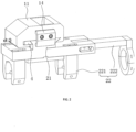
Fig. 1 is a schematic view showing a connection relationship of a quick-replace device for welding head according to a first embodiment of the present application with a framework and an ultrasonic triplet. -
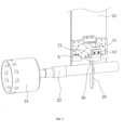
Fig. 2 is a schematic view of the quick-replace device for welding head according to the first embodiment of the present application. -
Fig. 3 is a partial structural view of the first embodiment of the present application for highlighting a fixing mechanism. -
Fig. 4 is a partial structural view of the first embodiment of the present application for highlighting a guiding groove and a guiding block. -
Fig. 5 is an exploded, partial structural view of the first embodiment of the present application for highlighting a movable mechanism. -
Fig. 6 is an exploded, partial structural view of the first embodiment of the present application for highlighting a position plate. -
Fig. 7 is a schematic view of the quick-replace device for welding head according to a second embodiment of the present application. -
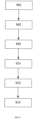
Fig. 8 is a flowchart of a quick-replace method for welding head according to an embodiment of the present application. -
- 1
- fixing mechanism
- 11
- fixing block
- 2
- movable mechanism
- 21
- mounting plate
- 22
- connecting assembly
- 221
- clamping jaw
- 222
- clamping member
- 2221
- connecting rod
- 2222
- hose clamp
- 3
- mounting groove
- 4
- abutting block
- 5
- position limiting bar
- 6
- first limiting groove
- 7
- chamfer
- 8
- second limiting groove
- 9
- adjusting member
- 10
- fastener
- 12
- guiding groove
- 13
- guiding block
- 14
- positioning block
- 15
- position plate
- 16
- position limiting slot
- 17
- position limiting bar
- 18
- fixture
- 19
- position limiting groove
- 23
- framework
- 24
- transducer
- 25
- amplitude modulator
- 26
- welding head
- 27
- latching slot
- 28
- first mounting hole
- 29
- second mounting hole
- 30
- connecting block
- 31
- connecting plate
- 32
- sliding groove
- Detailed description to the present application will be given below with reference to
Figs. 1-7 . - Embodiments of the present application disclose a quick-replace device for welding head of ultrasonic metal welding machine.
- Referring to
Fig. 1 , the quick-replace device for welding head of ultrasonic metal welding machine includes afixing mechanism 1 and amovable mechanism 2. Thefixing mechanism 1 is fixed to a side wall of aframework 23 through a connectingplate 31, and thefixing mechanism 1 is integrally formed with the connectingplate 31. Themovable mechanism 2 is used to fix the ultrasonic triplet, which includes atransducer 24, anamplitude modulator 25 and awelding head 26. Themovable mechanism 2 is detachably mounted in thefixing mechanism 1. During replacing thewelding head 26, thewelding head 26 can be removed when themovable mechanism 2 is detached from thefixing mechanism 1, and thewelding head 26 is installed when themovable mechanism 2 is mounted in thefixing mechanism 1. The welding head holding device is consisted of two separate parts, i.e., thefixing mechanism 1 and themovable mechanism 2, only themovable mechanism 2 needs to be disassembled and assembled for replacing thewelding head 26, which reduces the overall weight of the part to be replaced and makes the replacement of thewelding head 26 more labor-saving. - Referring to
Fig. 2 , thefixing mechanism 1 includes a fixingblock 11, which is fixedly mounted onto the side wall of theframework 23. The fixingblock 11 defines a mounting groove 3 which extends along a direction perpendicular to theframework 23. Both ends of the mounting groove 3 are open, and one of the open ends of the mounting groove 3 close to theframework 23 abuts against theframework 23. Themovable mechanism 2 includes a mountingplate 21 and a connectingassembly 22. The mountingplate 21 is slidably mounted into the mounting groove 3 along the direction perpendicular toframework 23. The connectingassembly 22 is used to fix the ultrasonic triplet, and is fixedly mounted at an end of the mountingplate 21 away from the fixingblock 11. Anabutting block 4 is slidably mounted into the fixingblock 11 along a direction perpendicular to the sliding direction of the mountingplate 21, and abuts against the mountingplate 21. Apositioning block 14 which is generally C-shaped is detachably mounted to a side wall of the fixingblock 11 away from theframework 23 by bolts. One end face of thepositioning block 14 abuts against the fixingblock 11, and the other end face of thepositioning block 14 abuts against the mountingplate 21. By means of sliding the mountingplate 21 into the mounting groove 3 of the fixingblock 11, themovable mechanism 2 is mounted into thefixing mechanism 1. After the assembly of the mountingplate 21, theabutting block 4 cooperates with the mounting groove 3 to fix the mountingplate 21 in a direction perpendicular to the sliding direction of the mountingplate 21, and thepositioning block 14 cooperates with theframework 23 to fix the mountingplate 21 in the sliding direction of the mountingplate 21. - Referring to
Fig. 3 andFig. 4 , an adjustingmember 9 is screwed in the fixingblock 11. The adjustingmember 9 extends through the fixingblock 11 and then threaded into theabutting block 4. Afastener 10 is mounted around and screwed on the adjustingmember 9, and abuts against an outer sidewall of the fixingblock 11. In this application, the adjustingmember 9 may be a differential screw, and thefastener 10 may be a nut. Two guidinggrooves 12 are defined in the fixingblock 11 along the sliding direction of theblock 4, two guidingblocks 13 are fixedly mounted to a side wall of theblock 4 close to theguide grooves 12 by bolts, and the guiding blocks 13 are slidably engaged into theguide grooves 12 along the sliding direction of theabutting block 4. During fixing the mountingplate 21, the adjustingmember 9 is rotated to drive the abuttingblock 4 to move. The guiding blocks 13 cooperate with theguide grooves 12 to make the movement of theabutting block 4 more stable. When theabutting block 4 moves to abut against the mountingplate 21, thefastener 10 is rotated to fix the adjustingmember 9 to make theabutting block 4 be fixed more stable. - Referring to
Fig. 3 andFig.5 , two side walls of the mountingplate 21 are respectively provided with aposition limiting bar 5 at an end thereof close to the fixingblock 11. Theposition limiting bar 5 is fixed to the sidewall, and extends along the sliding direction of the mountingplate 21. A cross section of theposition limiting bar 5 is generally triangular-shaped, and a width of the cross section gradually increases from bottom to top. A first limiting groove 6 is defined in an end of the fixingblock 11 away from theabutting block 4, and communicates with the mounting groove 3. Achamfer 7 is formed on theabutting block 4, which cooperates with a bottom wall of the mounting groove 3 to form a second limitinggroove 8. Cross sections of the first limiting groove 6 and second limitinggroove 8 are the same as the cross section of theposition limiting bar 5, and an adjustment range of theabutting block 4 is less than the maximum width of the cross section of theposition limiting bar 5. The twoposition limiting bars 5 are slidably mounted into the first limiting groove 6 and second limitinggroove 8 along the sliding direction of the mountingplate 21, respectively. When thewelding head 26 needs to be detached, firstly thepositioning block 14 is detached, and then the adjustingmember 9 is rotated to release the fixed state between theabutting block 4 and mountingplate 21. At this time, the mountingplate 21 is snapped in the first limiting groove 6 and second limitinggroove 8 of the mounting groove 3 through the position limiting bars 5. The mounting groove 3 provides a support to the mountingplate 21, which makes the mountingplate 21 not easy to have a safety risk of falling of the ultrasonic triplet during the disassembly of thewelding head 26 by the workers, and thus a single worker can disassemble thewelding head 26 by himself. The steps of assembly of thewelding head 26 are opposite to the above steps, and a single worker can also assemble thewelding head 26 by himself. Therefore, the replacement of thewelding head 26 is time-saving and labor-saving, and is more convenient and fast. - Referring to
Fig. 5 , theconnection assembly 22 includes two clampingjaws 221 and a clampingmember 222, wherein the clampingjaws 221 are used to fixedly clamp thewelding head 26, and the clampingmember 222 is used to fixedly clamp theamplitude modulator 25. Four slidinggrooves 32 are defined in the mountingplate 21 and extend along the axial direction of the ultrasonic triplet. The two clampingjaws 221 are fixed to a side wall of the mountingplate 21 away from the fixingblock 11 by bolts. The bolts are slidably mounted in the slidinggrooves 32, and the two clampingjaws 221 are provided with threaded holes. When the clampingjaws 221 clamp thewelding head 26, the bolts extend through the threaded holes to fix thewelding head 26. - The clamping
member 222 is mounted to a side wall of the mountingplate 21, and is capable of being adjusted along the axis direction of the ultrasonic triplet. The clampingmember 222 includes a connectingrod 2221 and ahose clamp 2222. Aposition limiting groove 19 is defined in the mountingplate 21, and the connectingrod 2221 slides into theposition limiting groove 19 of the mountingplate 21 along the axis direction of the ultrasonic triplet. Thehose clamp 2222 is fixed to an end of the connectingrod 2221 away from the mountingplate 21 by bolts, and is perpendicular to the connectingrod 2221 for fixing theamplitude modulator 25. By the means of sliding the connectingrod 2221 in theposition limiting groove 19 to drive thehose clamp 2222 to move, themovable mechanism 2 is suitable for ultrasonic triplets of different sizes. - A plurality of second mounting holes 29 are defined in the connecting
rod 2221 and evenly spaced from each other along the sliding direction of the connectingrod 2221. Three first mountingholes 28 are defined in the mountingplate 21 and evenly spaced from each other, and communicate with theposition limiting groove 19. Afixture 18 is screwed in the first mountinghole 28 of the mountingplate 21. Thefixture 18 extends through the first mountinghole 28 and then threads in the second mountinghole 29. Twofixtures 18 are provided and mounted in the first mountingholes 28 at two ends of the connectingrod 2221 in the sliding direction of the connectingrod 2221, respectively. In this application, thefixtures 18 may be bolts. After the connectingrod 2221 slides to adjust positions, it is fixed by thefixtures 18. By means of the twofixtures 18 which are arranged at two ends of the connectingrod 2221 in the sliding direction, the fixing effect of thefixtures 18 is improved. - Referring to
Fig. 6 , aposition plate 15 is detachably connected to a side wall of the mountingplate 21 far away from the fixingblock 11 by bolts and located between the two clampingjaws 221. A width of theposition plate 15 is about one half of that of the mountingplate 21, and a latchingslot 27 is defined in a side wall of theposition plate 15 which is close to a middle of the mountingplate 21 in the width direction. Thewelding head 26 abuts a side wall of the mountingplate 21 close to theposition plate 15 and is engaged in the latchingslot 27. Aposition limiting slot 16 is defined in a side wall of the mountingplate 21 close to theposition plate 15 and extends along the width direction of the mountingplate 21. Aposition limiting bar 17 is provided on a side wall of theposition plate 15 close to the mountingplate 21 and extends along the width direction of theposition plate 15. Theposition limiting bar 17 is slidably engaged into theposition limiting slot 16. During assembly of thewelding head 26, firstly theposition plate 15 is fix to the mountingplate 21 by bolts, and then thewelding head 26 is engaged into the latchingslot 27, so as to quickly position thewelding head 26 to make it be perpendicular to the mountingplate 21. The clampingjaws 221 clamp thewelding head 26 and slide towards theposition plate 15. When the clampingjaws 221 abut a side wall of theposition plate 15, the bolts are rotated to fix the clampingjaws 221, and at the same time, thewelding head 26 in the clampingjaw 221 is fixed by the bolts . After thewelding head 26 is assembled, theposition plate 15 is removed. By means of using theposition plate 15 to pre-position thewelding head 26, the positioning of thewelding head 26 is more convenient and accurate during installation. At the same time, using theposition plate 15 enables the workers with different work experience to assemble thewelding head 26 accurately, thereby reducing the assembly difficulty of thewelding head 26. - The implementation principle of the first embodiment is as follows: during assembly of the
welding head 26, firstly thewelding head 26 is mounted in the clampingjaw 221, and then theamplitude modulator 25 is mounted in the holdingclamp 2222, thereby finishing pre-assembly of the ultrasonic triplet. Theposition plate 15 is then mounted to the mountingplate 21 to further fix thewelding head 26, and the mountingplate 21 is slidably mounted into the mounting groove 3 of the fixingblock 11, so that theposition limiting bar 5 slides into the first limiting groove 6 and second limitinggroove 8. The adjustingmember 9 is then rotated to drive the abuttingblock 4 to move, so as to fix the mountingplate 21. Thefastener 10 is then rotated to fix the adjustingmember 9, and finally thepositioning block 14 is mounted on the fixingblock 11 by bolts to complete the assembly of thewelding head 26. Similarly, thewelding head 26 can be disassembled by reverse operation according to the above steps. During disassembling thewelding head 26, the mounting groove 3 provides a support to the mountingplate 21 through the cooperation of the first limit guide groove 6 and secondlimit guide groove 8 with theposition limiting bar 5, and thus a single worker can replace thewelding head 26, and the safety risk of falling of the ultrasonic triplet is not easy to occur, which makes the replacement of thewelding head 26 time-saving and labor-saving, and the operation more convenient and fast. - Referring to
Fig. 7 , the difference between this embodiment and the first embodiment is that: the connectingassembly 22 includes a connectingblock 30, one end of which is fixedly connected to the mountingplate 21 and the other end is fixedly connected to thewelding head 26. During assembly of thewelding head 26, the mountingplate 21 slides directly into the mounting groove 3 to assemble thewelding head 26, so that themovable mechanism 2 can be applied to different types of welding heads 26, improving the compatibility of the quick-replace device for welding head of ultrasonic metal welding machine. - The implementation principle of the second embodiment is as follows: during assembly of the
welding head 26, the mountingplate 21 slides into the mounting groove 3 of the fixingblock 11 to make theposition limiting bar 5 slide into the first limit guide groove 6 and secondlimit guide groove 8, the adjustingmember 9 is then rotated to drive the abuttingblock 4 to move to fix the mountingplate 21, thefastener 10 is then rotated to fix the adjustingmember 9, and finally thepositioning block 14 is fixed to the fixingblock 11 by bolts to complete the assembly of thewelding head 26. Similarly, thewelding head 26 can be disassembled by reverse operation according to the above steps. During assembly of thewelding head 26, the mountingplate 21 slides directly into the mounting groove 3 to assemble thewelding head 26, so that themovable mechanism 2 can be applied to different types of welding heads 26, improving the compatibility of the quick-replace device for welding head of ultrasonic metal welding machine. - In order to solve the problem that it is time-consuming, laborious and not easy to operate for assembly/disassembling the welding head, the embodiments of the present application further discloses a quick-replace method for welding head of ultrasonic metal welding machine, which is further described in detail with reference to
Figs. 1-8 below. - The quick-replace method for welding head of ultrasonic metal welding machine, which is implemented by the quick-replace device for welding head of ultrasonic metal welding machine described above, includes the following steps:
- S11, connecting a
welding head 26 to be assembled to the mountingplate 21 of themovable mechanism 2; - S12, mounting the mounting
plate 21 into the mounting groove 3 of the fixingblock 11 of thefixing mechanism 1 along a first direction; and - S13, moving the
abutting block 4 along a second direction to fix the mountingplate 21 in the mounting groove 3, wherein the second direction and the first direction form an angle with each other. - Preferably, the first direction and the second direction are perpendicular to each other, and contact surfaces of the
abutting block 4 and the mountingplate 21 are inclined to a certain angle, such as 45 degrees, with respect to the first direction and the second direction. During assembly of thewelding head 26, the sliding direction of the mountingplate 21 is different from the sliding direction of theabutting block 4, and the mountingplate 21 and abuttingblock 4 can be positioned by the inclined contact surfaces, thereby the mountingplate 21 can be better fixed in the mounting groove 3. - By adopting the above technical solution, during assembly of the
welding head 26, firstly the ultrasonic triplet is mounted to the mountingplate 21, and then the mountingplate 21 slides into the fixingblock 11 from the open side of the mounting groove 3. At this time, the mounting groove 3 of the fixingblock 11 supports the mountingplate 21, and then theabutting block 4 is used to fix the mountingplate 21, thus assembly of thewelding head 26 is completed. The whole assembly process can be completed by a single worker, and it can effectively avoid the safety risk of falling of the ultrasonic triplet. - In some embodiments, the method further comprises disassembling a
welding head 26 to be replaced before step S11, and disassembling thewelding head 26 to be replaced comprises the following steps: - S01, moving the
abutting block 4 along a third direction to loosen the mountingplate 21 which is fixed in the mounting groove 3 by theabutting block 4, wherein the third direction is opposite to the second direction; - S02, withdrawing the mounting
plate 21 from the mounting groove 3 along a fourth direction, wherein the fourth direction is opposite to the first direction; and - S03, removing the
welding head 26 to be replaced from the mountingplate 21 to which it is connected. - By adopting the above technical solution, during disassembling the
welding head 26, firstly theabutting block 4 is adjusted to release the fixed state with the mountingplate 21. At this time, the mounting groove 3 of the fixingblock 11 supports the mountingplate 21, and the ultrasonic triplet is not prone to the safety risk of falling, and then the mountingplate 21 slides out of the mounting groove 3 to complete the disassembly of thewelding head 26. The whole disassembly process can be completed by a single worker, and it can effectively avoid the safety risk of falling of the ultrasonic triplet. - According to the invention, the method further comprises: providing a
positioning block 14 and connecting thepositioning block 14 to the open side of the mounting groove 3 of the fixingblock 11 after step S13, so as to limit the movement of the mountingplate 21 along the fourth direction; and removing thepositioning block 14 which is connected to the open side of the mounting groove 3 of the fixingblock 11 before step S01. - By adopting the above technical solution, the
positioning block 14 is mounted onto the fixingblock 11 to limit the sliding of the mountingplate 21 after the assembly of the mountingplate 21 is finished, so as to further fix the mountingplate 21. Similarly, during disassembly of the mountingplate 21, it is necessary to remove thepositioning block 14 firstly. - In some embodiments, the step S11 comprises: providing a
position plate 15 with a latchingslot 27 and connecting theposition plate 15 to the mountingplate 21 detachably; docking thewelding head 26 to be assembled with the latchingslot 27 for positioning, so that thewelding head 26 is perpendicular to the mountingplate 21; clamping thewelding head 26 through the connectingassembly 22 and moving relative to the mountingplate 21 until the connectingassembly 22 contacts with theposition plate 15; fixing the connectingassembly 22 to the mountingplate 21; and removing theposition plate 15 from the mountingplate 21. - By adopting the above technical solution, during assembly of the
welding head 26, theposition plate 15 is mounted onto the mountingplate 21 for positing thewelding head 26, making the positioning of thewelding head 26 more convenient and accurate during installation. - The above descriptions are only preferred embodiments of the present invention and are not intended to limit the protection scope of the present invention, which is defined in the appended claims.
Claims (13)
- A quick-replace device for welding head of ultrasonic metal welding machine, whereinthe quick-replace device comprisesa fixing mechanism (1) for a fixed connection to a framework anda movable mechanism (2) for fixing an ultrasonic triplet, the ultrasonic triplet including a transducer, an amplitude modulator and a welding head,the movable mechanism (2) being detachably mounted in the fixing mechanism (1), and comprising a mounting plate (21) and a connecting assembly (22) for fixing the ultrasonic triplet, the connecting assembly (22) being arranged on the mounting plate (21);the fixing mechanism (1) comprising a fixing block (11) for the fixed connection to the framework,an abutting block (4) for fixing the mounting plate (21) being mounted in the fixing block (11), anda positioning block (14) which is detachably mounted on the fixing block (11) in a direction perpendicular to a sliding direction of the mounting plate (21) and abuts against the mounting plate (21) in a direction perpendicular to the adjusting direction of the abutting block (4), characterized in thatthe fixing mechanism (1) comprises a mounting groove (3) being defined in the fixing block (11) with at least one side thereof being open and extending in use in a direction perpendicular to the framework, the mounting plate (21) being slidably mounted in the mounting groove (3).
- The quick-replace device for welding head of ultrasonic metal welding machine according to claim 1, wherein
two sides of the mounting plate (21) along its sliding direction are provided with two position limiting bars (5), a first limiting groove (6) communicating with the mounting groove (3) is defined in the fixing block (11), a chamfer (7) is formed at an end of the abutting block (4) close to the mounting plate (21) and cooperates with a bottom of the mounting groove (3) to form a second limiting groove (8), and the two position limiting bars (5) are slidably mounted in the first limiting groove (6) and second limiting groove (8) along the sliding direction of the mounting plate (21), respectively. - The quick-replace device for welding head of ultrasonic metal welding machine according to claim 1, wherein
an end of the abutting block (4) away from the mounting plate (21) is provided with an adjusting member (9) for adjusting a position of the abutting block (4), and the fixing the adjusting member (9) is provided with a fastener (10) for fixing itself. - The quick-replace device for welding head of ultrasonic metal welding machine according to claim 1, wherein
a guiding groove (12) is defined in the fixing block (11), a guiding block (13) is provided on the abutting block (4), and the guide block (13) matches with the guiding groove (12)and is slidably mounted in the guiding groove (12) along an adjusting direction of the abutting block (4). - The quick-replace device for welding head of ultrasonic metal welding machine according to claim 1, wherein
the connecting assembly (22) comprises a clamping jaw (221) for fixing the welding head and a clamping member (222) for fixing the amplitude modulator, and the clamping member (222) is mounted on the mounting plate (21) and adjustable along an axis direction of the ultrasonic triplet. - The quick-replace device for welding head of ultrasonic metal welding machine according to claim 5, wherein
the clamping member (222) comprises a connecting rod (2221) and a hose clamp (2222), the connecting rod (2221) is slidably mounted on the mounting plate (21) along the axis direction of the ultrasonic triplet, the hose clamp (2222) is mounted at an end of the connecting rod (2221) away from the mounting plate (21) for fixing the amplitude modulator, and a fixture (18) for fixing the connecting rod (2221) is mounted on the mounting plate (21). - The quick-replace device for welding head of ultrasonic metal welding machine according to claim 6, wherein
a position limiting groove (19) is defined in the mounting plate (21) along a sliding direction of the connecting rod (2221), and the connecting rod (2221) matched with and is slidably mounted in the position limiting groove (19). - The quick-replace device for welding head of ultrasonic metal welding machine according to claim 1, wherein
a position plate (15) for facilitating positioning of the welding head during assembly of the welding head is provided on the mounting plate (21). - The quick-replace device for welding head of ultrasonic metal welding machine according to claim 8, wherein
a position limiting slot (16) is defined in a side wall of the mounting plate (21) close to the position plate (15), and a position limiting bar (17) is provided on a side wall of the position plate (15) close to the mounting plate (21), and the position limiting bar (17) matches with and is engaged in the position limiting slot (16). - A quick-replace method for welding head of ultrasonic metal welding machine, characterized in that the method is implemented by a quick-replace device for welding head of ultrasonic metal welding machine according to any one of claims 1-9, and the quick-replace method comprises the following steps:S11, connecting a welding head (26) to be assembled to the mounting plate (21) of the movable mechanism (2);S12, mounting the mounting plate (21) into the mounting groove (3) of the fixing block (11) of the fixing mechanism (1) along a first direction;S13, moving the abutting block (4) along a second direction to fix the mounting plate (21) in the mounting groove (3), wherein the second direction and the first direction form an angle with each other, wherein the method further comprises:providing a positioning block (14) and connecting the positioning block (14) to the open side of the mounting groove (3) of the fixing block (11) after step S13, so as to limit the movement of the mounting plate (21) along the fourth direction; and,removing the positioning block (14) which is connected to the open side of the mounting groove (3) of the fixing block (11) before step S01.
- The quick-replace method according to claim 10, wherein the method further comprises disassembling a welding head (26) to be replaced before step S11, which comprises the following steps:S01, moving the abutting block (4) along a third direction to loosen the mounting plate (21) which is fixed in the mounting groove (3) by the abutting block (4), wherein the third direction is opposite to the second direction;S02, withdrawing the mounting plate (21) from the mounting groove (3) along a fourth direction, wherein the fourth direction is opposite to the first direction;S03, removing the welding head (26) to be replaced from the mounting plate (21) to which it is connected.
- The quick-replace method according to claim 10, wherein the step S11 comprises:providing a position plate (15) with a latching slot (27) and connecting the position plate (15) to the mounting plate (21) detachably;docking the welding head (26) to be assembled with the latching slot (27) for positioning, so that the welding head (26) is perpendicular to the mounting plate (21);clamping the welding head (26) through the connecting assembly (22) and moving relative to the mounting plate (21) until the connecting assembly (22) contacts with the position plate (15);fixing the connecting assembly (22) to the mounting plate (21); andremoving the position plate (15) from the mounting plate (21).
- The quick-replace method according to claim 10, wherein the first direction and the second direction are perpendicular to each other, and contact surfaces of the abutting block (4) and the mounting plate (21) are inclined to a certain angle with respect to the first direction and the second direction.
Applications Claiming Priority (1)
| Application Number | Priority Date | Filing Date | Title |
|---|---|---|---|
| CN202210160112.8A CN114589391B (en) | 2022-02-22 | 2022-02-22 | A quick-change device for ultrasonic metal welding head |
Publications (3)
| Publication Number | Publication Date |
|---|---|
| EP4238683A1 EP4238683A1 (en) | 2023-09-06 |
| EP4238683C0 EP4238683C0 (en) | 2025-04-09 |
| EP4238683B1 true EP4238683B1 (en) | 2025-04-09 |
Family
ID=81806316
Family Applications (1)
| Application Number | Title | Priority Date | Filing Date |
|---|---|---|---|
| EP23157843.6A Active EP4238683B1 (en) | 2022-02-22 | 2023-02-21 | Quick-replace device and method for welding head of ultrasonic metal welding machine |
Country Status (2)
| Country | Link |
|---|---|
| EP (1) | EP4238683B1 (en) |
| CN (1) | CN114589391B (en) |
Families Citing this family (5)
| Publication number | Priority date | Publication date | Assignee | Title |
|---|---|---|---|---|
| CN116532778B (en) * | 2023-04-24 | 2023-11-07 | 东莞市索莱德自动化科技有限公司 | Ultrasonic seam welding equipment |
| CN117532886B (en) * | 2023-12-01 | 2024-11-12 | 江苏驰耐特防腐科技有限公司 | A device for welding PTFE lining of anti-corrosion storage tank |
| CN117733344B (en) * | 2024-02-21 | 2024-05-10 | 山西建投装备制造有限公司 | Automatic welding equipment and method for standard joint of construction lifter |
| CN117921272B (en) * | 2024-03-22 | 2024-06-21 | 安徽鸿昊钢结构彩板有限公司 | Light steel structure of movable house, assembling and welding method and device |
| CN119927495B (en) * | 2025-04-08 | 2025-06-20 | 山西瑞铭科技有限公司 | A concrete pole steel bar skeleton welding forming device |
Citations (3)
| Publication number | Priority date | Publication date | Assignee | Title |
|---|---|---|---|---|
| CN211165374U (en) | 2019-10-31 | 2020-08-04 | 无锡邦能超声科技有限公司 | Welding device holding mechanism of ultrasonic welding machine |
| CN213135413U (en) | 2020-09-04 | 2021-05-07 | 深圳市深发源精密科技有限公司 | Welding mechanism of ultrasonic welding machine |
| CN214602498U (en) | 2021-03-02 | 2021-11-05 | 上海幸义超声技术有限公司 | Triple-set mounting seat fixing device of ultrasonic welding machine |
Family Cites Families (6)
| Publication number | Priority date | Publication date | Assignee | Title |
|---|---|---|---|---|
| US9545751B2 (en) * | 2010-10-26 | 2017-01-17 | Rinco Ultrasonics USA, Inc. | Pedestal-mounted ultrasonic welding device |
| JP5737562B2 (en) * | 2011-02-09 | 2015-06-17 | 株式会社アドウェルズ | Resonator support device |
| CN207494778U (en) * | 2017-11-15 | 2018-06-15 | 东莞新能源科技有限公司 | welding device |
| JP7214991B2 (en) * | 2018-06-28 | 2023-01-31 | Tdk株式会社 | Ultrasonic bonding head, ultrasonic bonding apparatus and ultrasonic bonding method |
| CN211276959U (en) * | 2020-05-25 | 2020-08-18 | 常青智能科技(天津)有限公司 | Quick-change ultrasonic welding device |
| CN217551420U (en) * | 2022-02-22 | 2022-10-11 | 必能信超声(上海)有限公司 | Ultrasonic metal welding machine welding head quick change device |
-
2022
- 2022-02-22 CN CN202210160112.8A patent/CN114589391B/en active Active
-
2023
- 2023-02-21 EP EP23157843.6A patent/EP4238683B1/en active Active
Patent Citations (3)
| Publication number | Priority date | Publication date | Assignee | Title |
|---|---|---|---|---|
| CN211165374U (en) | 2019-10-31 | 2020-08-04 | 无锡邦能超声科技有限公司 | Welding device holding mechanism of ultrasonic welding machine |
| CN213135413U (en) | 2020-09-04 | 2021-05-07 | 深圳市深发源精密科技有限公司 | Welding mechanism of ultrasonic welding machine |
| CN214602498U (en) | 2021-03-02 | 2021-11-05 | 上海幸义超声技术有限公司 | Triple-set mounting seat fixing device of ultrasonic welding machine |
Also Published As
| Publication number | Publication date |
|---|---|
| EP4238683A1 (en) | 2023-09-06 |
| CN114589391A (en) | 2022-06-07 |
| CN114589391B (en) | 2025-09-26 |
| EP4238683C0 (en) | 2025-04-09 |
Similar Documents
| Publication | Publication Date | Title |
|---|---|---|
| EP4238683B1 (en) | Quick-replace device and method for welding head of ultrasonic metal welding machine | |
| KR200499458Y1 (en) | Quick replacement device for welding heads of an ultrasonic metal welding machine | |
| CN1590010A (en) | Tube clamping assembly | |
| KR101767345B1 (en) | Welding jig and welding method for manufacturing round metal plate for having various radius | |
| CN117086571A (en) | A kind of moving ring production equipment and production technology | |
| CN116100335B (en) | Auxiliary clamping tool for workpiece processing | |
| CN219562246U (en) | Tool clamp | |
| CN112318021A (en) | Welding positioning tool clamp | |
| CN219004634U (en) | Tool fixture of wedge type centering tensioning machine tool | |
| CN215281007U (en) | Semi-automatic hydraulic tool for special-shaped parts | |
| CN212191807U (en) | Welding robot with positioning device | |
| CN209936389U (en) | Automatic processingequipment of adjustment arm casing | |
| CN220295876U (en) | Robot clamp | |
| CN222768181U (en) | A positioning tool | |
| CN223603465U (en) | A quick-change lathe chuck | |
| CN222289912U (en) | Clamp for efficiently installing machining equipment | |
| CN222971400U (en) | Self-centering knurling device | |
| CN217912911U (en) | Machine tool clamping jaw device | |
| CN221247242U (en) | A slider groove wire cutting processing fixture | |
| CN221211459U (en) | Tool clamp | |
| CN114346566B (en) | Welding jig and welding equipment | |
| CN219837479U (en) | Multi-point machining clamp for medical instrument | |
| CN223406457U (en) | A fixing frame for hardware processing | |
| CN223834043U (en) | Beveling machine with cutter quick-release structure | |
| CN220240694U (en) | Anchor clamps are used in CNC lathe processing |
Legal Events
| Date | Code | Title | Description |
|---|---|---|---|
| PUAI | Public reference made under article 153(3) epc to a published international application that has entered the european phase |
Free format text: ORIGINAL CODE: 0009012 |
|
| STAA | Information on the status of an ep patent application or granted ep patent |
Free format text: STATUS: THE APPLICATION HAS BEEN PUBLISHED |
|
| AK | Designated contracting states |
Kind code of ref document: A1 Designated state(s): AL AT BE BG CH CY CZ DE DK EE ES FI FR GB GR HR HU IE IS IT LI LT LU LV MC ME MK MT NL NO PL PT RO RS SE SI SK SM TR |
|
| STAA | Information on the status of an ep patent application or granted ep patent |
Free format text: STATUS: REQUEST FOR EXAMINATION WAS MADE |
|
| 17P | Request for examination filed |
Effective date: 20231010 |
|
| RBV | Designated contracting states (corrected) |
Designated state(s): AL AT BE BG CH CY CZ DE DK EE ES FI FR GB GR HR HU IE IS IT LI LT LU LV MC ME MK MT NL NO PL PT RO RS SE SI SK SM TR |
|
| STAA | Information on the status of an ep patent application or granted ep patent |
Free format text: STATUS: EXAMINATION IS IN PROGRESS |
|
| 17Q | First examination report despatched |
Effective date: 20240124 |
|
| GRAP | Despatch of communication of intention to grant a patent |
Free format text: ORIGINAL CODE: EPIDOSNIGR1 |
|
| STAA | Information on the status of an ep patent application or granted ep patent |
Free format text: STATUS: GRANT OF PATENT IS INTENDED |
|
| INTG | Intention to grant announced |
Effective date: 20240816 |
|
| GRAJ | Information related to disapproval of communication of intention to grant by the applicant or resumption of examination proceedings by the epo deleted |
Free format text: ORIGINAL CODE: EPIDOSDIGR1 |
|
| STAA | Information on the status of an ep patent application or granted ep patent |
Free format text: STATUS: EXAMINATION IS IN PROGRESS |
|
| GRAP | Despatch of communication of intention to grant a patent |
Free format text: ORIGINAL CODE: EPIDOSNIGR1 |
|
| STAA | Information on the status of an ep patent application or granted ep patent |
Free format text: STATUS: GRANT OF PATENT IS INTENDED |
|
| INTC | Intention to grant announced (deleted) | ||
| INTG | Intention to grant announced |
Effective date: 20241206 |
|
| GRAS | Grant fee paid |
Free format text: ORIGINAL CODE: EPIDOSNIGR3 |
|
| GRAA | (expected) grant |
Free format text: ORIGINAL CODE: 0009210 |
|
| STAA | Information on the status of an ep patent application or granted ep patent |
Free format text: STATUS: THE PATENT HAS BEEN GRANTED |
|
| AK | Designated contracting states |
Kind code of ref document: B1 Designated state(s): AL AT BE BG CH CY CZ DE DK EE ES FI FR GB GR HR HU IE IS IT LI LT LU LV MC ME MK MT NL NO PL PT RO RS SE SI SK SM TR |
|
| REG | Reference to a national code |
Ref country code: GB Ref legal event code: FG4D |
|
| REG | Reference to a national code |
Ref country code: CH Ref legal event code: EP |
|
| REG | Reference to a national code |
Ref country code: DE Ref legal event code: R096 Ref document number: 602023002773 Country of ref document: DE |
|
| REG | Reference to a national code |
Ref country code: IE Ref legal event code: FG4D |
|
| U01 | Request for unitary effect filed |
Effective date: 20250507 |
|
| U07 | Unitary effect registered |
Designated state(s): AT BE BG DE DK EE FI FR IT LT LU LV MT NL PT RO SE SI Effective date: 20250513 |
|
| PG25 | Lapsed in a contracting state [announced via postgrant information from national office to epo] |
Ref country code: ES Free format text: LAPSE BECAUSE OF FAILURE TO SUBMIT A TRANSLATION OF THE DESCRIPTION OR TO PAY THE FEE WITHIN THE PRESCRIBED TIME-LIMIT Effective date: 20250409 |
|
| PG25 | Lapsed in a contracting state [announced via postgrant information from national office to epo] |
Ref country code: NO Free format text: LAPSE BECAUSE OF FAILURE TO SUBMIT A TRANSLATION OF THE DESCRIPTION OR TO PAY THE FEE WITHIN THE PRESCRIBED TIME-LIMIT Effective date: 20250709 Ref country code: GR Free format text: LAPSE BECAUSE OF FAILURE TO SUBMIT A TRANSLATION OF THE DESCRIPTION OR TO PAY THE FEE WITHIN THE PRESCRIBED TIME-LIMIT Effective date: 20250710 |
|
| PG25 | Lapsed in a contracting state [announced via postgrant information from national office to epo] |
Ref country code: PL Free format text: LAPSE BECAUSE OF FAILURE TO SUBMIT A TRANSLATION OF THE DESCRIPTION OR TO PAY THE FEE WITHIN THE PRESCRIBED TIME-LIMIT Effective date: 20250409 |
|
| PG25 | Lapsed in a contracting state [announced via postgrant information from national office to epo] |
Ref country code: HR Free format text: LAPSE BECAUSE OF FAILURE TO SUBMIT A TRANSLATION OF THE DESCRIPTION OR TO PAY THE FEE WITHIN THE PRESCRIBED TIME-LIMIT Effective date: 20250409 |
|
| PG25 | Lapsed in a contracting state [announced via postgrant information from national office to epo] |
Ref country code: RS Free format text: LAPSE BECAUSE OF FAILURE TO SUBMIT A TRANSLATION OF THE DESCRIPTION OR TO PAY THE FEE WITHIN THE PRESCRIBED TIME-LIMIT Effective date: 20250709 |
|
| PG25 | Lapsed in a contracting state [announced via postgrant information from national office to epo] |
Ref country code: IS Free format text: LAPSE BECAUSE OF FAILURE TO SUBMIT A TRANSLATION OF THE DESCRIPTION OR TO PAY THE FEE WITHIN THE PRESCRIBED TIME-LIMIT Effective date: 20250809 |
|
| PG25 | Lapsed in a contracting state [announced via postgrant information from national office to epo] |
Ref country code: SM Free format text: LAPSE BECAUSE OF FAILURE TO SUBMIT A TRANSLATION OF THE DESCRIPTION OR TO PAY THE FEE WITHIN THE PRESCRIBED TIME-LIMIT Effective date: 20250409 |
|
| PLBI | Opposition filed |
Free format text: ORIGINAL CODE: 0009260 |
|
| PG25 | Lapsed in a contracting state [announced via postgrant information from national office to epo] |
Ref country code: CZ Free format text: LAPSE BECAUSE OF FAILURE TO SUBMIT A TRANSLATION OF THE DESCRIPTION OR TO PAY THE FEE WITHIN THE PRESCRIBED TIME-LIMIT Effective date: 20250409 |
|
| REG | Reference to a national code |
Ref country code: CH Ref legal event code: L10 Free format text: ST27 STATUS EVENT CODE: U-0-0-L10-L00 (AS PROVIDED BY THE NATIONAL OFFICE) Effective date: 20260121 |
|
| PG25 | Lapsed in a contracting state [announced via postgrant information from national office to epo] |
Ref country code: SK Free format text: LAPSE BECAUSE OF FAILURE TO SUBMIT A TRANSLATION OF THE DESCRIPTION OR TO PAY THE FEE WITHIN THE PRESCRIBED TIME-LIMIT Effective date: 20250409 |
|
| 26 | Opposition filed |
Opponent name: HERRMANN ULTRASCHALLTECHNIK GMBH & CO. KG Effective date: 20260109 |
|
| PLAX | Notice of opposition and request to file observation + time limit sent |
Free format text: ORIGINAL CODE: EPIDOSNOBS2 |
|
| U20 | Renewal fee for the european patent with unitary effect paid |
Year of fee payment: 4 Effective date: 20260226 |