EP4238682B1 - Welding device and battery welding device - Google Patents
Welding device and battery welding device Download PDFInfo
- Publication number
- EP4238682B1 EP4238682B1 EP23156863.5A EP23156863A EP4238682B1 EP 4238682 B1 EP4238682 B1 EP 4238682B1 EP 23156863 A EP23156863 A EP 23156863A EP 4238682 B1 EP4238682 B1 EP 4238682B1
- Authority
- EP
- European Patent Office
- Prior art keywords
- welding
- drive mechanism
- fastening bracket
- welding head
- welding device
- Prior art date
- Legal status (The legal status is an assumption and is not a legal conclusion. Google has not performed a legal analysis and makes no representation as to the accuracy of the status listed.)
- Active
Links
Images



Classifications
-
- B—PERFORMING OPERATIONS; TRANSPORTING
- B23—MACHINE TOOLS; METAL-WORKING NOT OTHERWISE PROVIDED FOR
- B23K—SOLDERING OR UNSOLDERING; WELDING; CLADDING OR PLATING BY SOLDERING OR WELDING; CUTTING BY APPLYING HEAT LOCALLY, e.g. FLAME CUTTING; WORKING BY LASER BEAM
- B23K37/00—Auxiliary devices or processes, not specially adapted for a procedure covered by only one of the other main groups of this subclass
- B23K37/02—Carriages for supporting the welding or cutting element
- B23K37/0211—Carriages for supporting the welding or cutting element travelling on a guide member, e.g. rail, track
-
- B—PERFORMING OPERATIONS; TRANSPORTING
- B23—MACHINE TOOLS; METAL-WORKING NOT OTHERWISE PROVIDED FOR
- B23K—SOLDERING OR UNSOLDERING; WELDING; CLADDING OR PLATING BY SOLDERING OR WELDING; CUTTING BY APPLYING HEAT LOCALLY, e.g. FLAME CUTTING; WORKING BY LASER BEAM
- B23K20/00—Non-electric welding by applying impact or other pressure, with or without the application of heat, e.g. cladding or plating
- B23K20/10—Non-electric welding by applying impact or other pressure, with or without the application of heat, e.g. cladding or plating making use of vibrations, e.g. ultrasonic welding
-
- B—PERFORMING OPERATIONS; TRANSPORTING
- B23—MACHINE TOOLS; METAL-WORKING NOT OTHERWISE PROVIDED FOR
- B23K—SOLDERING OR UNSOLDERING; WELDING; CLADDING OR PLATING BY SOLDERING OR WELDING; CUTTING BY APPLYING HEAT LOCALLY, e.g. FLAME CUTTING; WORKING BY LASER BEAM
- B23K20/00—Non-electric welding by applying impact or other pressure, with or without the application of heat, e.g. cladding or plating
- B23K20/10—Non-electric welding by applying impact or other pressure, with or without the application of heat, e.g. cladding or plating making use of vibrations, e.g. ultrasonic welding
- B23K20/106—Features related to sonotrodes
-
- B—PERFORMING OPERATIONS; TRANSPORTING
- B23—MACHINE TOOLS; METAL-WORKING NOT OTHERWISE PROVIDED FOR
- B23K—SOLDERING OR UNSOLDERING; WELDING; CLADDING OR PLATING BY SOLDERING OR WELDING; CUTTING BY APPLYING HEAT LOCALLY, e.g. FLAME CUTTING; WORKING BY LASER BEAM
- B23K20/00—Non-electric welding by applying impact or other pressure, with or without the application of heat, e.g. cladding or plating
- B23K20/26—Auxiliary equipment
-
- B—PERFORMING OPERATIONS; TRANSPORTING
- B23—MACHINE TOOLS; METAL-WORKING NOT OTHERWISE PROVIDED FOR
- B23K—SOLDERING OR UNSOLDERING; WELDING; CLADDING OR PLATING BY SOLDERING OR WELDING; CUTTING BY APPLYING HEAT LOCALLY, e.g. FLAME CUTTING; WORKING BY LASER BEAM
- B23K37/00—Auxiliary devices or processes, not specially adapted for a procedure covered by only one of the other main groups of this subclass
- B23K37/02—Carriages for supporting the welding or cutting element
- B23K37/0247—Driving means
-
- B—PERFORMING OPERATIONS; TRANSPORTING
- B23—MACHINE TOOLS; METAL-WORKING NOT OTHERWISE PROVIDED FOR
- B23K—SOLDERING OR UNSOLDERING; WELDING; CLADDING OR PLATING BY SOLDERING OR WELDING; CUTTING BY APPLYING HEAT LOCALLY, e.g. FLAME CUTTING; WORKING BY LASER BEAM
- B23K37/00—Auxiliary devices or processes, not specially adapted for a procedure covered by only one of the other main groups of this subclass
- B23K37/04—Auxiliary devices or processes, not specially adapted for a procedure covered by only one of the other main groups of this subclass for holding or positioning work
- B23K37/0426—Fixtures for other work
-
- B—PERFORMING OPERATIONS; TRANSPORTING
- B23—MACHINE TOOLS; METAL-WORKING NOT OTHERWISE PROVIDED FOR
- B23K—SOLDERING OR UNSOLDERING; WELDING; CLADDING OR PLATING BY SOLDERING OR WELDING; CUTTING BY APPLYING HEAT LOCALLY, e.g. FLAME CUTTING; WORKING BY LASER BEAM
- B23K37/00—Auxiliary devices or processes, not specially adapted for a procedure covered by only one of the other main groups of this subclass
- B23K37/04—Auxiliary devices or processes, not specially adapted for a procedure covered by only one of the other main groups of this subclass for holding or positioning work
- B23K37/0426—Fixtures for other work
- B23K37/0435—Clamps
-
- B—PERFORMING OPERATIONS; TRANSPORTING
- B23—MACHINE TOOLS; METAL-WORKING NOT OTHERWISE PROVIDED FOR
- B23K—SOLDERING OR UNSOLDERING; WELDING; CLADDING OR PLATING BY SOLDERING OR WELDING; CUTTING BY APPLYING HEAT LOCALLY, e.g. FLAME CUTTING; WORKING BY LASER BEAM
- B23K2101/00—Articles made by soldering, welding or cutting
- B23K2101/36—Electric or electronic devices
-
- B—PERFORMING OPERATIONS; TRANSPORTING
- B23—MACHINE TOOLS; METAL-WORKING NOT OTHERWISE PROVIDED FOR
- B23K—SOLDERING OR UNSOLDERING; WELDING; CLADDING OR PLATING BY SOLDERING OR WELDING; CUTTING BY APPLYING HEAT LOCALLY, e.g. FLAME CUTTING; WORKING BY LASER BEAM
- B23K2101/00—Articles made by soldering, welding or cutting
- B23K2101/36—Electric or electronic devices
- B23K2101/38—Conductors
-
- B—PERFORMING OPERATIONS; TRANSPORTING
- B23—MACHINE TOOLS; METAL-WORKING NOT OTHERWISE PROVIDED FOR
- B23K—SOLDERING OR UNSOLDERING; WELDING; CLADDING OR PLATING BY SOLDERING OR WELDING; CUTTING BY APPLYING HEAT LOCALLY, e.g. FLAME CUTTING; WORKING BY LASER BEAM
- B23K2103/00—Materials to be soldered, welded or cut
- B23K2103/08—Non-ferrous metals or alloys
- B23K2103/10—Aluminium or alloys thereof
-
- Y—GENERAL TAGGING OF NEW TECHNOLOGICAL DEVELOPMENTS; GENERAL TAGGING OF CROSS-SECTIONAL TECHNOLOGIES SPANNING OVER SEVERAL SECTIONS OF THE IPC; TECHNICAL SUBJECTS COVERED BY FORMER USPC CROSS-REFERENCE ART COLLECTIONS [XRACs] AND DIGESTS
- Y02—TECHNOLOGIES OR APPLICATIONS FOR MITIGATION OR ADAPTATION AGAINST CLIMATE CHANGE
- Y02E—REDUCTION OF GREENHOUSE GAS [GHG] EMISSIONS, RELATED TO ENERGY GENERATION, TRANSMISSION OR DISTRIBUTION
- Y02E60/00—Enabling technologies; Technologies with a potential or indirect contribution to GHG emissions mitigation
- Y02E60/10—Energy storage using batteries
-
- Y—GENERAL TAGGING OF NEW TECHNOLOGICAL DEVELOPMENTS; GENERAL TAGGING OF CROSS-SECTIONAL TECHNOLOGIES SPANNING OVER SEVERAL SECTIONS OF THE IPC; TECHNICAL SUBJECTS COVERED BY FORMER USPC CROSS-REFERENCE ART COLLECTIONS [XRACs] AND DIGESTS
- Y02—TECHNOLOGIES OR APPLICATIONS FOR MITIGATION OR ADAPTATION AGAINST CLIMATE CHANGE
- Y02P—CLIMATE CHANGE MITIGATION TECHNOLOGIES IN THE PRODUCTION OR PROCESSING OF GOODS
- Y02P70/00—Climate change mitigation technologies in the production process for final industrial or consumer products
- Y02P70/50—Manufacturing or production processes characterised by the final manufactured product
Definitions
- the utility model pertains to the technical field of ultrasonic welding, and more specifically relates to a welding device and a battery welding according to the preamble of claims 1 and 9 respectively (see for example CN 208 961 225 U ).
- Ultrasonic welding technology is highly advantageous in the tab welding process of traction batteries.
- an existing ultrasonic welding device uses ultrasonic wave to weld a tab of a battery cell to an adapting sheet, a protective pressure plate needs to be pressed downward to fasten the battery cell, and then an ultrasonic welder is adjusted to a welding position through three-axis movements for ultrasonic welding. After welding is completed, the ultrasonic welder is adjusted back to the initial position through three-axis movements, and the protective pressure plate is lifted to leave the battery cell.
- the existing ultrasonic welding device needs to be adjusted in place through three-axis movements of its base, leading to low welding efficiency.
- US patent application 2 066 791 A discloses a welding apparatus.
- the apparatus comprises two arms A, A1 pivoted between their ends at a, a1, respectively.
- the rear ends of the arms A, A1 can be forced apart by a hydraulic ram and cylinder B, B1 to cause clamping jaws D, D1, to grip the plates E with a heavy pressure of about four to twelve tons per square inch of the clamping area.
- the forward ends of the arms A, A1, to carry the electrodes F, F1, which, can be moved by hydraulic means to contact with the plates and to bear against the plates with comparatively light pressure.
- Chinese patent application 113 290 312 A discloses an ultrasonic welding device which is not easy to cause poor welding.
- the ultrasonic welding head (21) performs ultrasonic welding on the peripheral edge parts of the laminated sheets (15, 16) by moving in the X direction in a state in which the crimping surface (21a) of the ultrasonic welding head (21) is crimped on the peripheral edge parts of the laminated sheets (15, 16).
- the crimping surface (21a) of the ultrasonic horn (21) has an arc shape protruding in the crimping direction.
- Embodiments of the present invention aim to provide a welding device and a battery welding device, to resolve a technical problem of low efficiency of welding a to-be-welded member in the prior art.
- a first aspect of the present invention is a welding device as defined in claim 1, including a frame, a welding assembly, a fastening bracket, a protective pressure plate, a first drive mechanism, and a second drive mechanism, where the welding assembly includes a first welding head and a second welding head that are arranged opposite each other, and the first welding head is fastened on the frame; the fastening bracket is movably provided on the frame, and the second welding head is fastened on the fastening bracket; the protective pressure plate is fastened on the fastening bracket or the second welding head; the first drive mechanism is drivingly connected to the fastening bracket and configured to drive the fastening bracket so that the second welding head reaches a position of a welding point and the protective pressure plate presses against a to-be-welded member; and the second drive mechanism is drivingly connected to the second welding head and configured to drive the second welding head to weld the to-be-welded member.
- the second welding head of the welding device is fastened on the fastening bracket, and the protective pressure plate is fastened on the fastening bracket or the second welding head.
- the first drive mechanism can simultaneously drive the second welding head to reach the position of the welding point and drive the protective pressure plate to press against the to-be-welded member. After the second welding head reaches the position of the welding point, the second drive mechanism drives the second welding head reaching the position of the welding point to weld the to-be-welded member.
- the first drive mechanism of the welding device is connected to the second welding head and the protective pressure plate via the fastening bracket, and the first drive mechanism drives both the second welding head and the protective pressure plate via the fastening bracket, so as to compress and weld the to-be-welded member via one shaft, thereby improving welding efficiency.
- the welding assembly further includes an ultrasonic generator, the second welding head is connected to the ultrasonic generator, and the ultrasonic generator is fixedly connected to the fastening bracket.
- the welding device adopts ultrasonic welding, achieving fast welding speed, high welding strength, and stable welding process.
- the first drive mechanism includes a servo motor, a screw rod, and a screw nut, the servo motor is drivingly connected to the screw rod, the screw nut is provided on the screw rod and drivingly connected to the screw rod, the screw rod is provided on the frame, and the fastening bracket is connected to the screw nut.
- the first drive mechanism adopts the screw rod-driven structure, achieving high drive efficiency, high drive accuracy, and stable movement of the second welding head and the protective pressure plate.
- ball screw driving is essentially rolling friction with small frictional resistance, ensuring long service life.
- the second drive mechanism is an air cylinder
- a fastening end of the air cylinder is installed on the screw nut
- a power output end of the air cylinder is drivingly connected to the fastening bracket.
- the second drive mechanism in this embodiment is an air cylinder, able to adjust the welding pressure on the second welding head by adjusting air pressure in the air cylinder.
- the air cylinder features simple structure and cost-efficient.
- the screw nut is provided with an installation plate
- the installation plate is provided with a guide structure
- the fastening bracket is slidably provided on the guide structure to limit a movement direction of the fastening bracket.
- the guide structure is provided to limit movement direction of the fastening bracket, so that the second welding head and the protective pressure plate move in the preset direction, thereby improving welding accuracy of the first welding head and the second welding head.
- the guide structure includes a slide rail and a slide block, the slide block is slidably connected to the slide rail, and the fastening bracket is fastened on the slide block.
- the guide structure uses the slide rail and the slide block, with simple structure and easy installation, which can ensure the accuracy of the pressing direction of the protective pressure plate and the movement direction of the second welding head, thereby improving the welding accuracy of the welding device.
- the welding device further includes a third drive mechanism, and the third drive mechanism is drivingly connected to the frame to drive the frame to move.
- the third drive mechanism drives the frame to move, so as to drive the first welding head to reach the position of the welding point.
- the third drive mechanism drives the first welding head to leave the position of the welding point, so that the welding fixture moves the to-be-welded member from the position of the welding point, thereby avoiding interference between the welding fixture and the first welding head and improving the welding efficiency.
- the third drive mechanism is an electric cylinder, and a power output end of the electric cylinder is connected to the frame; the frame includes a base, and the power output end of the electric cylinder is installed on the base; and the base is provided with a guide column, and a fastening end of the electric cylinder is provided with a guide sleeve matching the guide column.
- the third drive mechanism is an electric cylinder that features high accuracy, high integration, and powerful environmental adaptability.
- a motor of the electric cylinder uses a drive mechanism such as a synchronous pulley, a gear, or a worm gear to drive the screw to rotate, which has advantages such as flexible cooperation, easy installation, high strength, small return clearance, long service life, good control performance, high control precision, and low maintenance costs.
- Guide structures that cooperate with each other are provided on the frame and the electric cylinder, to ensure the linear movement of the frame, thereby improving the movement accuracy of the first welding head.
- the protective pressure plate includes a connecting bracket and a protective plate movably connected to the connecting bracket, the protective plate is configured to press against the to-be-welded member, and the connecting bracket is connected to the fastening bracket; and a guide column is provided on the protective plate, a compression spring fits around the guide column, and a guide sleeve matching the guide column is provided on the connecting bracket.
- the protective plate and the connecting bracket in this embodiment are guided by the guide structure through cooperation of the guide sleeve and the guide column, which ensures that the protective pressure plate presses against the to-be-welded member consistently in the same direction, thereby avoiding deviation of the to-be-welded member due to deflection of the pressing direction of the protective pressure plate.
- the compression spring is provided, and the compression spring can act as a cushion while the to-be-welded member is being pressed by the protective plate, thereby preventing the protective plate from damaging the to-be-welded member.
- a second aspect of the present invention is a battery welding device as defined in claim 9, including a welding fixture and the foregoing welding device, where the to-be-welded member is an electrode assembly, the welding fixture is configured to fasten the electrode assembly, and the welding device is configured to weld the electrode assembly located at a welding point.
- the battery welding device includes a welding fixture and the foregoing welding device.
- the welding fixture fastens the electrode assembly, and after the first welding head reaches the position of the welding point, the first drive mechanism can drive the second welding head to reach the position of the welding point and also drive the protective pressure plate to press against the electrode assembly. After the second welding head reaches the position of the welding point, the second drive mechanism drives the second welding head reaching the position of the welding point to weld the electrode assembly.
- the first drive mechanism of the battery welding device is connected to the second welding head and the protective pressure plate via the fastening bracket, and the first drive mechanism drives both the second welding head and the protective pressure plate via the fastening bracket, so as to compress and weld the electrode assembly via one shaft, thereby improving welding efficiency.
- connection should be understood in their general senses.
- the terms may refer to a mechanical connection or an electrical connection, or may refer to a direct connection, an indirect connection via an intermediate medium, an internal connection between two elements, or an interaction between two elements.
- connect should be understood in their general senses.
- the terms may refer to a mechanical connection or an electrical connection, or may refer to a direct connection, an indirect connection via an intermediate medium, an internal connection between two elements, or an interaction between two elements.
- orientations or positional relationships indicated by the terms “length”, “width”, “upper”, “lower”, “front”, “rear”, “left”, “right”, “perpendicular”, “horizontal”, “top”, “bottom”, “inside”, “outside”, and the like are based on the orientations or positional relationships shown in the accompanying drawings, are merely intended to facilitate the descriptions of the utility model and simplify the descriptions, are not intended to indicate or imply that the indicated apparatuses or components must have specific orientations, or be constructed and operated for a specific orientation, and therefore shall not be construed as a limitation to the utility model.
- first and second are merely intended for a purpose of description, and shall not be understood as an indication or implication of relative importance or implicit indication of the number of indicated technical features. Therefore, a feature limited by “first” or “second” may explicitly or implicitly include one or more features.
- lithium-ion batteries As a new type of secondary battery, lithium-ion batteries have advantages such as high energy density and power density, high working voltage, light weight, small size, long cycle life, good safety, and environmental friendliness, and has broad application prospects in portable electric appliances, electric tools, great energy storage, and power supplies for electric transportation.
- aluminum-shelled battery cells are most commonly used in lithium-ion batteries.
- a battery cell with multiple tabs is made through winding.
- the battery cell including multiple tabs is connected to a top cover through an adapting sheet.
- the tabs of the battery cell and the adapting sheet are usually connected through ultrasonic welding.
- a protective pressure plate needs to be pressed downward to cover the battery cell, and then an ultrasonic welder is adjusted to a welding position through three-axis movements for ultrasonic welding. After welding, the ultrasonic welder is adjusted to a zero position through three-axis movements (the three axes refer to three directions of X axis, Y axis and Z axis in the three-dimensional Cartesian coordinate system), and the protective pressure plate is lifted to leave the battery cell.
- the existing ultrasonic welder has the following disadvantages: First, it takes long for adjusting the welder to the position for welding through three-axis movements of the base.
- a protective pressure plate is in an independent position, and after the welding fixture drives the battery cell in place, the protective pressure plate first presses against the battery cell for protection, which wastes time and reduces efficiency.
- the welding efficiency of the ultrasonic welder is usually improved by increasing the number of ultrasonic welders, which increases costs of devices.
- the utility model provides a welding device and a battery welding device. The welding device in this application can also be applied to ultrasonic welding in another field.
- FIG. 1 is a schematic structural diagram of a welding device and a welding fixture at a viewing angle.
- FIG. 2 is a schematic structural diagram of a welding device and a welding fixture at another viewing angle.
- FIG. 3 is a schematic structural diagram of a welding device and a welding fixture at still another viewing angle according to an embodiment of the utility mode angle.
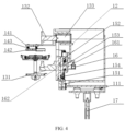
- FIG. 4 is a schematic structural diagram of a cross section along A-A in FIG. 3 .
- a first aspect provides a welding device 1, including a frame 11, a fastening bracket 12, a welding assembly 13, a protective pressure plate 14, a first drive mechanism 15, and a second drive mechanism 16.
- the welding assembly 13 includes a first welding head 131 and a second welding head 132 that are arranged opposite each other, and the first welding head 131 is fastened on the frame 11.
- the fastening bracket 12 is movably provided on the frame 11, and the second welding head 132 is fastened on the fastening bracket 12.
- the protective pressure plate 14 is fastened on the fastening bracket 12.
- the first drive mechanism 15 is drivingly connected to the fastening bracket 12 and configured to drive the fastening bracket 12 so that the second welding head 132 reaches a position of a welding point and the protective pressure plate 14 presses against a to-be-welded member.
- the second drive mechanism 16 is drivingly connected to the second welding head 132 and configured to drive the second welding head 132 to weld the to-be-welded member.
- the frame 11 is configured to mount the welding assembly 13, the fastening bracket 12, the protective pressure plate 14, the first drive mechanism 15, and the second drive mechanism 16.
- a specific size and material of the frame 11 are not specifically limited in this embodiment.
- the frame is generally a metal structure.
- the welding assembly 13 includes the first welding head 131 and the second welding head 132, and the first welding head 131 mates with the second welding head 132 to finish welding the to-be-welded member.
- the welding assembly 13 can be an ultrasonic welding assembly.
- the first welding head 131 and the second welding head 132 are ultrasonic welding heads that cooperate with each other.
- the protective pressure plate 14 is configured to press against the to-be-welded member in a welding process, to avoid movement of the to-be-welded member in the welding process which otherwise affects welding quality.
- a specific structure of the protective pressure plate 14 is not specifically limited in this embodiment.
- the protective pressure plate 14 in this embodiment is fastened on the fastening bracket 12.
- the protective pressure plate 14 may alternatively fastened on the second welding head 132.
- the second welding head 132 and the protective pressure plate 14 in this embodiment are both connected to one shaft of the fastening bracket 12.
- the first drive mechanism 15 is drivingly connected to the fastening bracket 12, when driving the fastening bracket 12 to move, the first drive mechanism 15 in this embodiment drives both the second welding head 132 and the protective pressure plate 14 to move, so that the first drive mechanism 15 is drivingly connected to the second welding head 132 and the protective pressure plate 14 via one shaft.
- a specific structure and size of the fastening bracket 12 are not specifically limited in this embodiment.
- the first drive mechanism 15 is configured to drive the fastening bracket 12 so that the second welding head 132 reaches the position of the welding point and the protective pressure plate 14 presses against the to-be-welded member. Because both the second welding head 132 and the protective pressure plate 14 are connected to the fastening bracket 12, when the first drive mechanism 15 drives the fastening bracket 12 to move, the second welding head 132 and the protective pressure plate 14 in this embodiment move synchronously. To be specific, the protective pressure plate 14 and the second welding head 132 complete compression and welding via one shaft.
- the first drive mechanism 15 in this embodiment is configured to drive the fastening bracket 12, so that the fastening bracket 12 drives the second welding head 132 to reach the position of the welding point, and the protective pressure plate 14 to press against the to-be-welded member.
- a specific structure of the first drive mechanism 15 is not specifically limited in this embodiment.
- the second drive mechanism 16 is configured to drive the second welding head 132 to weld the to-be-welded member.
- the second drive mechanism 16 in this embodiment drives the second welding head 132 to the position of the welding point and cooperate with the first welding head 131 to weld the to-be-welded member.
- a specific structure of the second drive mechanism 16 is not specifically limited in this embodiment.
- the second drive mechanism 16 may be an air cylinder.
- the second welding head 132 of the welding device is fastened on the fastening bracket 12, and the protective pressure plate 14 is fastened on the fastening bracket 12.
- the first drive mechanism 15 can drive the second welding head 132 to reach the position of the welding point and also drive the protective pressure plate 14 to press against the to-be-welded member.
- the second drive mechanism 16 drives the second welding head 132 reaching the position of the welding point to weld the to-be-welded member.
- the first drive mechanism 15 of the welding device is connected to the second welding head 132 and the protective pressure plate 14 via the fastening bracket 12, and the first drive mechanism 15 drives both the second welding head 132 and the protective pressure plate 14 via the fastening bracket 12, to compress and weld the to-be-welded member via one shaft, thereby improving welding efficiency.
- the welding assembly further includes an ultrasonic generator 133, the second welding head 132 is connected to the ultrasonic generator 133, and the ultrasonic generator 133 and the protective pressure plate 14 are both connected to an end of the fastening bracket 12.
- the welding assembly 13 of the welding device includes the ultrasonic generator 133.
- the welding device welds the to-be-welded member via ultrasonic welding.
- the ultrasonic welding is to transfer high-frequency vibration waves to surfaces of two to-be-welded objects to cause the surfaces of the two objects to rub against each other under pressure, so as to fuse molecular layers.
- the ultrasonic generator 133 is fixedly connected to the second welding head 132, and the welding device implements ultrasonic welding via cooperation of the second welding head 132 and the first welding head 131.
- the first welding head 131 in this embodiment is designed with knurling, and cooperates with the second welding head 132 to weld the to-be-welded member during the ultrasonic welding.
- a specific structure of the ultrasonic generator 133 in the welding device in this embodiment is not specifically limited.
- the welding device in this embodiment adopts ultrasonic welding, achieving fast welding speed, high welding strength, and stable welding process.
- the welding device in this embodiment can be used for welding tabs in the electrode assembly, or welding tabs and an adapting sheet in the electrode assembly.
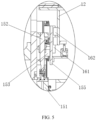
- FIG. 5 is an enlarged schematic diagram of a local structure in FIG. 4 .
- the first drive mechanism 15 is a screw rod-driven structure
- the first drive mechanism includes a servo motor 151, a screw rod 152, and a screw nut 153
- the servo motor 151 is drivingly connected to the screw rod 152
- the screw nut 153 is provided on the screw rod 151 and drivingly connected to the screw rod 151
- another end of the fastening bracket 12 is connected to the screw nut 153.
- the servo motor 151 is configured to drive the screw rod 152 to rotate.
- a specific form of the servo motor is not specifically limited in this embodiment.
- the screw rod 152 may be a slide screw rod or a rolling screw rod.
- the screw rod 152 in this embodiment is a ball screw.
- the fastening bracket 12 is fastened on the screw nut 153.
- the first drive mechanism 15 is configured to drive the fastening bracket 12 so that the second welding head 132 reaches the position of the welding point and the protective pressure plate 14 presses against the to-be-welded member.
- the first drive mechanism 15 adopts the screw rod-driven structure, achieving high drive efficiency, high drive accuracy, and stable movement of the second welding head 132 and the protective pressure plate 14.
- ball screw driving is essentially rolling friction with small frictional resistance, thereby implementing long service life.
- the second drive mechanism 16 is an air cylinder, a fastening end of the air cylinder is installed on the screw nut 153, and a power output end of the air cylinder is drivingly connected to the fastening bracket 12.
- the second drive mechanism 16 in this embodiment is configured to drive the second welding head 132 to weld the to-be-welded member, and the second drive mechanism 16 is a drive mechanism that can adjust welding force.
- the second drive mechanism 16 in this embodiment is an air cylinder, a power output end of the air cylinder (piston rod of the air cylinder) is fixedly connected to the fastening bracket 12, and the power output end of the air cylinder drives the fastening bracket 12 to move. Because the second welding head 132 is fixedly connected to the fastening bracket 12, the fastening bracket 12 drives the second welding head 132 to perform a welding motion.
- the second drive mechanism 16 is an air cylinder.
- Adjusting air pressure in the air cylinder can change magnitude of pressure output by the air cylinder, thereby adjusting magnitude of welding force applied on the second welding head 132.
- a technician can adjust the air pressure in the air cylinder based on a welding effect of the to-be-welded member, so as to adjust the welding force to make the welding effect of the welding device meet a preset requirement.
- the second drive mechanism 16 implements welding, and the second drive mechanism 16 is an air cylinder, facilitating adjustment of the welding pressure on the second welding head 132.
- the air cylinder has a simple structure and low cost.
- the screw nut 153 is provided with an installation plate 155
- the installation plate 155 is provided with a guide structure
- the fastening bracket 12 is slidably provided on the guide structure to limit a movement direction of the fastening bracket 12.
- the screw nut 153 in this embodiment is provided with the guide structure for limiting the movement direction of the fastening bracket 12, so that the fastening bracket 12 moves in the preset movement direction. Because the second welding head 132 and the protective pressure plate 14 are fixedly connected to the fastening bracket 12 directly or indirectly, the second welding head 132 and the protective pressure plate 14 move in a preset direction.
- the first welding head 131 and the second welding head 132 in this embodiment are arranged vertically, and the guide structure limits movement of the second welding head 132 in the vertical direction, so that the second welding head 132 is always aligned with the first welding head 131.
- a specific structure of the guide structure is not specifically limited in this embodiment.
- the guide structure is provided to limit the movement direction of the fastening bracket 12, so that the second welding head 132 and the protective pressure plate 14 move in the preset direction and the second welding head 132 is always aligned with the first welding head 131, thereby improving welding accuracy of the first welding head 131 and the second welding head 132.
- the guide structure includes a slide rail 161 and a slide block 162, the slide block 162 is slidably connected to the slide rail 161, and the fastening bracket 12 is fastened on the slide block 162.
- the guide structure in this embodiment is the slide rail structure, and the slide rail structure includes the slide rail 161 and the slide block 162.
- the slide rail 161 in this embodiment is installed on the installation plate, the fastening bracket 12 is fastened on the slide block 162, and the fastening bracket 12 moves along the slide rail 161, so that the second welding head 132 and the protective pressure plate 14 move in the preset direction.
- the welding device can ensure that the second welding head 132 and the protective pressure plate 14 move in the preset direction, and ensure accuracy of a pressing direction of the protective pressure plate 14 and the movement direction of the second welding head 132, thereby ensuring the welding accuracy of the welding assembly.
- the guide structure in this embodiment uses the slide rail 161 and the slide block 162, with simple structure and easy installation, which can ensure the accuracy of the pressing direction of the protective pressure plate 14 and the movement direction of the second welding head 132, thereby improving the welding accuracy of the welding device.
- the welding device further includes a third drive mechanism 17, and the third drive mechanism 17 is configured to drive the frame 11 to move.
- the third drive mechanism 17 is configured to drive the frame 11 to move. For example, before welding, the third drive mechanism 17 drives the frame 11 to move to a welding position. Because the first welding head 131 is fastened on the frame 11, after the third drive mechanism 17 drives the frame 11 to the welding position, the first welding head 131 reaches the position of the welding point. Then the first drive mechanism 15 drives the fastening bracket 12 to cause the second welding head 132 to reach the position of the welding point and the protective pressure plate 14 to press against the to-be-welded member, and the second drive mechanism 16 drives the second welding head 132 to weld the to-be-welded member. After the welding is completed, the first drive mechanism 15 drives the protective pressure plate 14 and the second welding head 132 to leave the position of the welding point, and the third drive mechanism 17 drives the frame to cause the first welding head 132 to leave the position of the welding point.
- the third drive mechanism 17 drives the frame 11 to move, so as to drive the first welding head 132 to reach the position of the welding point.
- the third drive mechanism 17 drives the first welding head 131 to leave the position of the welding point, so that the welding fixture moves the to-be-welded member from the position of the welding point, thereby avoiding interference between the welding fixture and the first welding head 131 and improving the welding efficiency.
- the third drive mechanism 17 is an electric cylinder, a power output end of the electric cylinder is connected to the frame 11, the frame 11 includes a base 111, the power output end of the electric cylinder is installed on the base 111, the base 111 is provided with a guide column, and a fastening end of the electric cylinder is provided with a guide sleeve matching the guide column.
- the electric cylinder in this embodiment is configured to drive the frame 11 to move, so that the first welding head 131 reaches the position of the welding point.
- a specific structure of the electric cylinder is not specifically limited in this embodiment.
- the frame 11 in this embodiment includes the base 111, the power output end of the electric cylinder is installed on the base 111 in a simple installation way.
- the guide column is provided on the base 111, and the fastening end of the electric cylinder is provided with the guide sleeve.
- the third drive mechanism 17 in this embodiment is an electric cylinder that has high accuracy, high integration, and strong environmental adaptability.
- a motor of the electric cylinder drives the screw to rotate via a drive mechanism such as a synchronous pulley, a gear, or a worm gear, which has advantages such as flexible cooperation, easy installation, high strength, small return space, long service life, good control performance, high control precision, and low maintenance costs.
- Guide structures that cooperate with each other are provided on the frame and the electric cylinder, to ensure the linear movement of the frame, thereby improving the movement accuracy of the first welding head 131.
- the protective pressure plate 14 includes a connecting bracket 141 and a protective plate 142 connected to the connecting bracket 141 movably, the protective plate 142 is configured to press against the to-be-welded member, and the connecting bracket 141 is connected to the fastening bracket 12.
- the guide column is provided on the protective plate 142, a compression spring 143 fits around the guide column, and a guide sleeve matching the guide column is provided on the connecting bracket 141.
- the protective pressure plate 14 includes the connecting bracket 141 and the protective plate 142, and the protective plate 142 is configured to press against the to-be-welded member in a welding process.
- a shape and size of the protective plate 142 in this embodiment can be preset based on a shape and size of the to-be-welded member, area of a pressing surface of the protective plate 142 is generally greater than area of a to-be-pressed surface of the to-be-welded member.
- the dimension of the protective plate 142 is not specifically limited in this embodiment.
- the connecting bracket 141 in this embodiment is fixedly connected to the fastening bracket 12, the protective plate 142 and the connecting bracket 141 are guided by the guide structure through cooperation of the guide sleeve and the guide column, and the compression spring 143 fits around the guide column.
- the guide sleeve and the guide column cooperate to guide the pressing of the protective plate 142. Specific numbers of guide sleeves and guide columns are not specifically limited in this embodiment.
- the protective plate 142 and the connecting bracket 141 in this embodiment are guided by the guide structure through cooperation of the guide sleeve and the guide column, which ensures that the protective pressure plate 14 presses against the to-be-welded member consistently in the same direction, thereby avoiding deviation of the to-be-welded member due to deflection of the pressing direction of the protective pressure plate 14.
- the compression spring 143 is provided, and the compression spring 143 can act as a cushion while the to-be-welded member is being pressed by the protective plate 142, thereby preventing the protective plate 142 from damaging the to-be-welded member.
- a second aspect of the embodiments of this application provides a battery welding device, including a welding fixture 2 and the welding device 1 in the foregoing embodiments, where the to-be-welded member is an electrode assembly, the welding fixture 2 is configured to fasten the electrode assembly, and the welding device 1 is configured to weld the electrode assembly at a position of a welding point.
- the welding device 1 includes a frame 11, a fastening bracket 12, a welding assembly 13, a protective pressure plate 14, a first drive mechanism 15, and a second drive mechanism 16.
- the welding assembly 13 includes a first welding head 131 and a second welding head 132 that are arranged opposite each other, and the first welding head 131 is fastened on the frame 11.
- the fastening bracket 12 is movably provided on the frame 11, and the second welding head 132 is fastened on the fastening bracket 12.
- the protective pressure plate 14 is fastened on the fastening bracket 12 or the second welding head 132.
- the first drive mechanism 15 is drivingly connected to the fastening bracket 12 and configured to drive the fastening bracket 12 so that the second welding head 132 reaches a position of a welding point and the protective pressure plate 14 presses against a to-be-welded member.
- the second drive mechanism 16 is drivingly connected to the second welding head 132 and configured to drive the second welding head 132 to weld the to-be-welded member.
- the battery welding device in this embodiment can be used to weld multiple tabs in a battery cell, for example, multiple positive tabs or multiple negative tabs in one battery cell.
- FIG. 6 is a schematic structural diagram of an electrode assembly in a welding process according to an embodiment of the present invention. Referring to FIG. 6 , the battery welding device in this embodiment can also be used for welding tabs B and adapting sheets C of two battery cells A.
- a third drive mechanism 17 drives a frame 11 to move up to cause a first welding head 131 to move to a position of a welding point, a servo motor 151 of the first drive mechanism 15 rotates to drive coupling 154 and a screw rod 152 to rotate, the screw rod 152 rotates to drive a screw nut 153 to move down, the fastening bracket 12 moves down, and the second welding head 132 moves to the position of the welding point;
- the battery welding device provided in this embodiment of the present invention includes a welding fixture and the welding device in the foregoing embodiments.
- the welding fixture fastens the electrode assembly
- the first drive mechanism can drive the second welding head to reach the position of the welding point and also drive the protective pressure plate to press against the electrode assembly.
- the second drive mechanism drives the second welding head reaching the position of the welding point to weld the electrode assembly.
- the first drive mechanism of the battery welding device is connected to the second welding head and the protective pressure plate via the fastening bracket.
- the first drive mechanism drives both the second welding head and the protective pressure plate via the fastening bracket, to compress and weld the electrode assembly via one shaft, thereby improving welding efficiency.
Landscapes
- Engineering & Computer Science (AREA)
- Mechanical Engineering (AREA)
- Physics & Mathematics (AREA)
- Optics & Photonics (AREA)
- Resistance Welding (AREA)
Description
- The utility model pertains to the technical field of ultrasonic welding, and more specifically relates to a welding device and a battery welding according to the preamble of
claims 1 and 9 respectively (see for exampleCN 208 961 225 U ). - Ultrasonic welding technology is highly advantageous in the tab welding process of traction batteries. When an existing ultrasonic welding device uses ultrasonic wave to weld a tab of a battery cell to an adapting sheet, a protective pressure plate needs to be pressed downward to fasten the battery cell, and then an ultrasonic welder is adjusted to a welding position through three-axis movements for ultrasonic welding. After welding is completed, the ultrasonic welder is adjusted back to the initial position through three-axis movements, and the protective pressure plate is lifted to leave the battery cell. The existing ultrasonic welding device needs to be adjusted in place through three-axis movements of its base, leading to low welding efficiency.
US discloses a welding apparatus. The apparatus comprises two arms A, A1 pivoted between their ends at a, a1, respectively. The rear ends of the arms A, A1 can be forced apart by a hydraulic ram and cylinder B, B1 to cause clamping jaws D, D1, to grip the plates E with a heavy pressure of about four to twelve tons per square inch of the clamping area. The forward ends of the arms A, A1, to carry the electrodes F, F1, which, can be moved by hydraulic means to contact with the plates and to bear against the plates with comparatively light pressure. Further,patent application 2 066 791 AChinese patent application 113 290 312 A discloses an ultrasonic welding device which is not easy to cause poor welding. The ultrasonic welding head (21) performs ultrasonic welding on the peripheral edge parts of the laminated sheets (15, 16) by moving in the X direction in a state in which the crimping surface (21a) of the ultrasonic welding head (21) is crimped on the peripheral edge parts of the laminated sheets (15, 16). The crimping surface (21a) of the ultrasonic horn (21) has an arc shape protruding in the crimping direction. - Embodiments of the present invention aim to provide a welding device and a battery welding device, to resolve a technical problem of low efficiency of welding a to-be-welded member in the prior art.
- To achieve the foregoing objective, the technical solutions used in the utility model are as follows: A first aspect of the present invention is a welding device as defined in
claim 1, including a frame, a welding assembly, a fastening bracket, a protective pressure plate, a first drive mechanism, and a second drive mechanism, where the welding assembly includes a first welding head and a second welding head that are arranged opposite each other, and the first welding head is fastened on the frame; the fastening bracket is movably provided on the frame, and the second welding head is fastened on the fastening bracket; the protective pressure plate is fastened on the fastening bracket or the second welding head; the first drive mechanism is drivingly connected to the fastening bracket and configured to drive the fastening bracket so that the second welding head reaches a position of a welding point and the protective pressure plate presses against a to-be-welded member; and the second drive mechanism is drivingly connected to the second welding head and configured to drive the second welding head to weld the to-be-welded member. - The second welding head of the welding device is fastened on the fastening bracket, and the protective pressure plate is fastened on the fastening bracket or the second welding head. When the to-be-welded member is being welded, the first drive mechanism can simultaneously drive the second welding head to reach the position of the welding point and drive the protective pressure plate to press against the to-be-welded member. After the second welding head reaches the position of the welding point, the second drive mechanism drives the second welding head reaching the position of the welding point to weld the to-be-welded member. The first drive mechanism of the welding device is connected to the second welding head and the protective pressure plate via the fastening bracket, and the first drive mechanism drives both the second welding head and the protective pressure plate via the fastening bracket, so as to compress and weld the to-be-welded member via one shaft, thereby improving welding efficiency.
- In some embodiments, the welding assembly further includes an ultrasonic generator, the second welding head is connected to the ultrasonic generator, and the ultrasonic generator is fixedly connected to the fastening bracket. The welding device adopts ultrasonic welding, achieving fast welding speed, high welding strength, and stable welding process.
- According to the present invention, the first drive mechanism includes a servo motor, a screw rod, and a screw nut, the servo motor is drivingly connected to the screw rod, the screw nut is provided on the screw rod and drivingly connected to the screw rod, the screw rod is provided on the frame, and the fastening bracket is connected to the screw nut. The first drive mechanism adopts the screw rod-driven structure, achieving high drive efficiency, high drive accuracy, and stable movement of the second welding head and the protective pressure plate. In addition, ball screw driving is essentially rolling friction with small frictional resistance, ensuring long service life.
- In some embodiments, the second drive mechanism is an air cylinder, a fastening end of the air cylinder is installed on the screw nut, and a power output end of the air cylinder is drivingly connected to the fastening bracket. The second drive mechanism in this embodiment is an air cylinder, able to adjust the welding pressure on the second welding head by adjusting air pressure in the air cylinder. In addition, the air cylinder features simple structure and cost-efficient.
- In some embodiments, the screw nut is provided with an installation plate, the installation plate is provided with a guide structure, and the fastening bracket is slidably provided on the guide structure to limit a movement direction of the fastening bracket. The guide structure is provided to limit movement direction of the fastening bracket, so that the second welding head and the protective pressure plate move in the preset direction, thereby improving welding accuracy of the first welding head and the second welding head.
- In some embodiments, the guide structure includes a slide rail and a slide block, the slide block is slidably connected to the slide rail, and the fastening bracket is fastened on the slide block. The guide structure uses the slide rail and the slide block, with simple structure and easy installation, which can ensure the accuracy of the pressing direction of the protective pressure plate and the movement direction of the second welding head, thereby improving the welding accuracy of the welding device.
- In some embodiments, the welding device further includes a third drive mechanism, and the third drive mechanism is drivingly connected to the frame to drive the frame to move. Before the welding, the third drive mechanism drives the frame to move, so as to drive the first welding head to reach the position of the welding point. After the welding is completed, the third drive mechanism drives the first welding head to leave the position of the welding point, so that the welding fixture moves the to-be-welded member from the position of the welding point, thereby avoiding interference between the welding fixture and the first welding head and improving the welding efficiency.
- In some embodiments, the third drive mechanism is an electric cylinder, and a power output end of the electric cylinder is connected to the frame; the frame includes a base, and the power output end of the electric cylinder is installed on the base; and the base is provided with a guide column, and a fastening end of the electric cylinder is provided with a guide sleeve matching the guide column. The third drive mechanism is an electric cylinder that features high accuracy, high integration, and powerful environmental adaptability. A motor of the electric cylinder uses a drive mechanism such as a synchronous pulley, a gear, or a worm gear to drive the screw to rotate, which has advantages such as flexible cooperation, easy installation, high strength, small return clearance, long service life, good control performance, high control precision, and low maintenance costs. Guide structures that cooperate with each other are provided on the frame and the electric cylinder, to ensure the linear movement of the frame, thereby improving the movement accuracy of the first welding head.
- In some embodiments, the protective pressure plate includes a connecting bracket and a protective plate movably connected to the connecting bracket, the protective plate is configured to press against the to-be-welded member, and the connecting bracket is connected to the fastening bracket; and
a guide column is provided on the protective plate, a compression spring fits around the guide column, and a guide sleeve matching the guide column is provided on the connecting bracket. The protective plate and the connecting bracket in this embodiment are guided by the guide structure through cooperation of the guide sleeve and the guide column, which ensures that the protective pressure plate presses against the to-be-welded member consistently in the same direction, thereby avoiding deviation of the to-be-welded member due to deflection of the pressing direction of the protective pressure plate. The compression spring is provided, and the compression spring can act as a cushion while the to-be-welded member is being pressed by the protective plate, thereby preventing the protective plate from damaging the to-be-welded member. - A second aspect of the present invention is a battery welding device as defined in claim 9, including a welding fixture and the foregoing welding device, where the to-be-welded member is an electrode assembly, the welding fixture is configured to fasten the electrode assembly, and the welding device is configured to weld the electrode assembly located at a welding point.
- The battery welding device includes a welding fixture and the foregoing welding device. In welding of the electrode assembly, the welding fixture fastens the electrode assembly, and after the first welding head reaches the position of the welding point, the first drive mechanism can drive the second welding head to reach the position of the welding point and also drive the protective pressure plate to press against the electrode assembly. After the second welding head reaches the position of the welding point, the second drive mechanism drives the second welding head reaching the position of the welding point to weld the electrode assembly. The first drive mechanism of the battery welding device is connected to the second welding head and the protective pressure plate via the fastening bracket, and the first drive mechanism drives both the second welding head and the protective pressure plate via the fastening bracket, so as to compress and weld the electrode assembly via one shaft, thereby improving welding efficiency.
- The foregoing description is merely an overview of the technical solution of this application. For a better understanding of the technical means in this application such that they can be implemented according to the content of the specification, and to make the above and other objectives, features and advantages of this application more obvious and easier to understand, the following describes specific embodiments of this application.
- To describe the technical solutions in the embodiments of the present invention more clearly, the following briefly describes the accompanying drawings required for describing the embodiments or the prior art. Apparently, the accompanying drawings in the following description show merely some of the embodiments of the present invention as defined in the appended claims, and persons of ordinary skill in the art may still derive other drawings from these accompanying drawings without creative efforts.
-
FIG. 1 is a schematic structural diagram of a welding device and a welding fixture at a viewing angle; -
FIG. 2 is a schematic structural diagram of a welding device and a welding fixture at another viewing angle; -
FIG. 3 is a schematic structural diagram of a welding device and a welding fixture at still another viewing angle; -
FIG. 4 is a schematic structural diagram of a cross section along A-A inFIG. 3 ; -
FIG. 5 is an enlarged schematic diagram of a local structure inFIG. 4 ; and -
FIG. 6 is a schematic structural diagram of an electrode assembly in a welding process. - Reference signs in the figure:
- 1. welding device; 2. welding fixture; 11. frame; 12. fastening bracket; 13. welding assembly;
- 14. protective pressure plate; 15. first drive mechanism; 16. second drive mechanism; 111. base;
- 131. first welding head; 132. second welding head; 133. ultrasonic generator; 141. connecting bracket;
- 142. protective plate; 143. compression spring; 151. servo motor; 152. screw rod; 153. screw nut;
- 154. coupling; 161. slide rail; 162. slide block; and 17. third drive mechanism.
- To make the objectives, technical solutions, and advantages of the embodiments of the present invention clearer, the following clearly and completely describes the technical solutions in the embodiments of the present invention with reference to the accompanying drawings in the embodiments of the present invention.
- In the description of the present invention, it should be noted that the terms "include", "contain" and any other variants used herein mean to cover the non-exclusive inclusion, for example, a process, method, system, product, or device that includes a list of steps or units is not necessarily limited to those units, but may include other units not expressly listed or inherent to such a process, method, system, product, or device.
- In addition, in this application, unless otherwise specified and defined explicitly, the terms "connect", "join", "fix", and "install" should be understood in their general senses. For example, the terms may refer to a mechanical connection or an electrical connection, or may refer to a direct connection, an indirect connection via an intermediate medium, an internal connection between two elements, or an interaction between two elements. Unless otherwise defined explicitly, persons of ordinary skill in the art can understand specific meanings of the foregoing terms in this application based on specific situations.
- It should be understood that the orientations or positional relationships indicated by the terms "length", "width", "upper", "lower", "front", "rear", "left", "right", "perpendicular", "horizontal", "top", "bottom", "inside", "outside", and the like are based on the orientations or positional relationships shown in the accompanying drawings, are merely intended to facilitate the descriptions of the utility model and simplify the descriptions, are not intended to indicate or imply that the indicated apparatuses or components must have specific orientations, or be constructed and operated for a specific orientation, and therefore shall not be construed as a limitation to the utility model.
- In addition, the terms "first" and "second" are merely intended for a purpose of description, and shall not be understood as an indication or implication of relative importance or implicit indication of the number of indicated technical features. Therefore, a feature limited by "first" or "second" may explicitly or implicitly include one or more features.
- As a new type of secondary battery, lithium-ion batteries have advantages such as high energy density and power density, high working voltage, light weight, small size, long cycle life, good safety, and environmental friendliness, and has broad application prospects in portable electric appliances, electric tools, great energy storage, and power supplies for electric transportation. Currently, aluminum-shelled battery cells are most commonly used in lithium-ion batteries. A battery cell with multiple tabs is made through winding. The battery cell including multiple tabs is connected to a top cover through an adapting sheet. The tabs of the battery cell and the adapting sheet are usually connected through ultrasonic welding.
- When an existing ultrasonic welder uses ultrasonic wave to weld a tab to an adapting sheet, a protective pressure plate needs to be pressed downward to cover the battery cell, and then an ultrasonic welder is adjusted to a welding position through three-axis movements for ultrasonic welding. After welding, the ultrasonic welder is adjusted to a zero position through three-axis movements (the three axes refer to three directions of X axis, Y axis and Z axis in the three-dimensional Cartesian coordinate system), and the protective pressure plate is lifted to leave the battery cell. The existing ultrasonic welder has the following disadvantages: First, it takes long for adjusting the welder to the position for welding through three-axis movements of the base. Second, a protective pressure plate is in an independent position, and after the welding fixture drives the battery cell in place, the protective pressure plate first presses against the battery cell for protection, which wastes time and reduces efficiency. Currently, the welding efficiency of the ultrasonic welder is usually improved by increasing the number of ultrasonic welders, which increases costs of devices. In view of the foregoing problems, the utility model provides a welding device and a battery welding device. The welding device in this application can also be applied to ultrasonic welding in another field.
- The following describes in detail the welding device and the battery welding device provided in the utility model with reference to specific embodiments.
-
FIG. 1 is a schematic structural diagram of a welding device and a welding fixture at a viewing angle.FIG. 2 is a schematic structural diagram of a welding device and a welding fixture at another viewing angle.FIG. 3 is a schematic structural diagram of a welding device and a welding fixture at still another viewing angle according to an embodiment of the utility mode angle.FIG. 4 is a schematic structural diagram of a cross section along A-A inFIG. 3 . As shown inFIG. 1 to FIG. 4 , a first aspect provides awelding device 1, including aframe 11, afastening bracket 12, awelding assembly 13, aprotective pressure plate 14, afirst drive mechanism 15, and asecond drive mechanism 16. Thewelding assembly 13 includes afirst welding head 131 and asecond welding head 132 that are arranged opposite each other, and thefirst welding head 131 is fastened on theframe 11. Thefastening bracket 12 is movably provided on theframe 11, and thesecond welding head 132 is fastened on thefastening bracket 12. Theprotective pressure plate 14 is fastened on thefastening bracket 12. Thefirst drive mechanism 15 is drivingly connected to thefastening bracket 12 and configured to drive thefastening bracket 12 so that thesecond welding head 132 reaches a position of a welding point and theprotective pressure plate 14 presses against a to-be-welded member. Thesecond drive mechanism 16 is drivingly connected to thesecond welding head 132 and configured to drive thesecond welding head 132 to weld the to-be-welded member. - The
frame 11 is configured to mount thewelding assembly 13, thefastening bracket 12, theprotective pressure plate 14, thefirst drive mechanism 15, and thesecond drive mechanism 16. A specific size and material of theframe 11 are not specifically limited in this embodiment. To improve service life of theframe 11, the frame is generally a metal structure. - The
welding assembly 13 includes thefirst welding head 131 and thesecond welding head 132, and thefirst welding head 131 mates with thesecond welding head 132 to finish welding the to-be-welded member. For example, thewelding assembly 13 can be an ultrasonic welding assembly. For example, thefirst welding head 131 and thesecond welding head 132 are ultrasonic welding heads that cooperate with each other. - The
protective pressure plate 14 is configured to press against the to-be-welded member in a welding process, to avoid movement of the to-be-welded member in the welding process which otherwise affects welding quality. A specific structure of theprotective pressure plate 14 is not specifically limited in this embodiment. Theprotective pressure plate 14 in this embodiment is fastened on thefastening bracket 12. In another embodiment, theprotective pressure plate 14 may alternatively fastened on thesecond welding head 132. Thesecond welding head 132 and theprotective pressure plate 14 in this embodiment are both connected to one shaft of thefastening bracket 12. Because thefirst drive mechanism 15 is drivingly connected to thefastening bracket 12, when driving thefastening bracket 12 to move, thefirst drive mechanism 15 in this embodiment drives both thesecond welding head 132 and theprotective pressure plate 14 to move, so that thefirst drive mechanism 15 is drivingly connected to thesecond welding head 132 and theprotective pressure plate 14 via one shaft. A specific structure and size of thefastening bracket 12 are not specifically limited in this embodiment. - The
first drive mechanism 15 is configured to drive thefastening bracket 12 so that thesecond welding head 132 reaches the position of the welding point and theprotective pressure plate 14 presses against the to-be-welded member. Because both thesecond welding head 132 and theprotective pressure plate 14 are connected to thefastening bracket 12, when thefirst drive mechanism 15 drives thefastening bracket 12 to move, thesecond welding head 132 and theprotective pressure plate 14 in this embodiment move synchronously. To be specific, theprotective pressure plate 14 and thesecond welding head 132 complete compression and welding via one shaft. - The
first drive mechanism 15 in this embodiment is configured to drive thefastening bracket 12, so that thefastening bracket 12 drives thesecond welding head 132 to reach the position of the welding point, and theprotective pressure plate 14 to press against the to-be-welded member. A specific structure of thefirst drive mechanism 15 is not specifically limited in this embodiment. - The
second drive mechanism 16 is configured to drive thesecond welding head 132 to weld the to-be-welded member. Thesecond drive mechanism 16 in this embodiment drives thesecond welding head 132 to the position of the welding point and cooperate with thefirst welding head 131 to weld the to-be-welded member. A specific structure of thesecond drive mechanism 16 is not specifically limited in this embodiment. For example, thesecond drive mechanism 16 may be an air cylinder. - The
second welding head 132 of the welding device is fastened on thefastening bracket 12, and theprotective pressure plate 14 is fastened on thefastening bracket 12. In welding of the to-be-welded member, thefirst drive mechanism 15 can drive thesecond welding head 132 to reach the position of the welding point and also drive theprotective pressure plate 14 to press against the to-be-welded member. After thesecond welding head 132 reaches the position of the welding point, thesecond drive mechanism 16 drives thesecond welding head 132 reaching the position of the welding point to weld the to-be-welded member. Thefirst drive mechanism 15 of the welding device is connected to thesecond welding head 132 and theprotective pressure plate 14 via thefastening bracket 12, and thefirst drive mechanism 15 drives both thesecond welding head 132 and theprotective pressure plate 14 via thefastening bracket 12, to compress and weld the to-be-welded member via one shaft, thereby improving welding efficiency. - In some embodiments, referring to
FIG. 1 andFIG. 4 , the welding assembly further includes anultrasonic generator 133, thesecond welding head 132 is connected to theultrasonic generator 133, and theultrasonic generator 133 and theprotective pressure plate 14 are both connected to an end of thefastening bracket 12. - The
welding assembly 13 of the welding device includes theultrasonic generator 133. The welding device welds the to-be-welded member via ultrasonic welding. The ultrasonic welding is to transfer high-frequency vibration waves to surfaces of two to-be-welded objects to cause the surfaces of the two objects to rub against each other under pressure, so as to fuse molecular layers. Theultrasonic generator 133 is fixedly connected to thesecond welding head 132, and the welding device implements ultrasonic welding via cooperation of thesecond welding head 132 and thefirst welding head 131. Thefirst welding head 131 in this embodiment is designed with knurling, and cooperates with thesecond welding head 132 to weld the to-be-welded member during the ultrasonic welding. A specific structure of theultrasonic generator 133 in the welding device in this embodiment is not specifically limited. - The welding device in this embodiment adopts ultrasonic welding, achieving fast welding speed, high welding strength, and stable welding process. The welding device in this embodiment can be used for welding tabs in the electrode assembly, or welding tabs and an adapting sheet in the electrode assembly.
-
FIG. 5 is an enlarged schematic diagram of a local structure inFIG. 4 . Referring toFIG. 1 ,FIG. 4 , andFIG. 5 , thefirst drive mechanism 15 is a screw rod-driven structure, the first drive mechanism includes aservo motor 151, ascrew rod 152, and ascrew nut 153, theservo motor 151 is drivingly connected to thescrew rod 152, thescrew nut 153 is provided on thescrew rod 151 and drivingly connected to thescrew rod 151, and another end of thefastening bracket 12 is connected to thescrew nut 153. - According to the present invention, the
servo motor 151 is configured to drive thescrew rod 152 to rotate. A specific form of the servo motor is not specifically limited in this embodiment. Thescrew rod 152 may be a slide screw rod or a rolling screw rod. For example, thescrew rod 152 in this embodiment is a ball screw. Thefastening bracket 12 is fastened on thescrew nut 153. When theservo motor 151 drives thescrew rod 152 to rotate, thescrew nut 153 moves on thescrew rod 152 linearly, and thescrew nut 153 drives thefastening bracket 12 to move linearly, thereby driving thesecond welding head 132 and theprotective pressure plate 14 to move linearly. - According to the present invention, the
first drive mechanism 15 is configured to drive thefastening bracket 12 so that thesecond welding head 132 reaches the position of the welding point and theprotective pressure plate 14 presses against the to-be-welded member. Thefirst drive mechanism 15 adopts the screw rod-driven structure, achieving high drive efficiency, high drive accuracy, and stable movement of thesecond welding head 132 and theprotective pressure plate 14. In addition, ball screw driving is essentially rolling friction with small frictional resistance, thereby implementing long service life. - In some embodiments, referring to
FIG. 4 , thesecond drive mechanism 16 is an air cylinder, a fastening end of the air cylinder is installed on thescrew nut 153, and a power output end of the air cylinder is drivingly connected to thefastening bracket 12. - The
second drive mechanism 16 in this embodiment is configured to drive thesecond welding head 132 to weld the to-be-welded member, and thesecond drive mechanism 16 is a drive mechanism that can adjust welding force. Thesecond drive mechanism 16 in this embodiment is an air cylinder, a power output end of the air cylinder (piston rod of the air cylinder) is fixedly connected to thefastening bracket 12, and the power output end of the air cylinder drives thefastening bracket 12 to move. Because thesecond welding head 132 is fixedly connected to thefastening bracket 12, thefastening bracket 12 drives thesecond welding head 132 to perform a welding motion. In this embodiment, thesecond drive mechanism 16 is an air cylinder. Adjusting air pressure in the air cylinder can change magnitude of pressure output by the air cylinder, thereby adjusting magnitude of welding force applied on thesecond welding head 132. For example, in the welding process, a technician can adjust the air pressure in the air cylinder based on a welding effect of the to-be-welded member, so as to adjust the welding force to make the welding effect of the welding device meet a preset requirement. - In this embodiment, the
second drive mechanism 16 implements welding, and thesecond drive mechanism 16 is an air cylinder, facilitating adjustment of the welding pressure on thesecond welding head 132. In addition, the air cylinder has a simple structure and low cost. - In some embodiments, referring to
FIG. 4 andFIG. 5 , thescrew nut 153 is provided with aninstallation plate 155, theinstallation plate 155 is provided with a guide structure, and thefastening bracket 12 is slidably provided on the guide structure to limit a movement direction of thefastening bracket 12. - The
screw nut 153 in this embodiment is provided with the guide structure for limiting the movement direction of thefastening bracket 12, so that thefastening bracket 12 moves in the preset movement direction. Because thesecond welding head 132 and theprotective pressure plate 14 are fixedly connected to thefastening bracket 12 directly or indirectly, thesecond welding head 132 and theprotective pressure plate 14 move in a preset direction. For example, thefirst welding head 131 and thesecond welding head 132 in this embodiment are arranged vertically, and the guide structure limits movement of thesecond welding head 132 in the vertical direction, so that thesecond welding head 132 is always aligned with thefirst welding head 131. A specific structure of the guide structure is not specifically limited in this embodiment. - In this embodiment, the guide structure is provided to limit the movement direction of the
fastening bracket 12, so that thesecond welding head 132 and theprotective pressure plate 14 move in the preset direction and thesecond welding head 132 is always aligned with thefirst welding head 131, thereby improving welding accuracy of thefirst welding head 131 and thesecond welding head 132. - In some embodiments, referring to
FIG. 4 andFIG. 5 , the guide structure includes aslide rail 161 and aslide block 162, theslide block 162 is slidably connected to theslide rail 161, and thefastening bracket 12 is fastened on theslide block 162. - The guide structure in this embodiment is the slide rail structure, and the slide rail structure includes the
slide rail 161 and theslide block 162. Theslide rail 161 in this embodiment is installed on the installation plate, thefastening bracket 12 is fastened on theslide block 162, and thefastening bracket 12 moves along theslide rail 161, so that thesecond welding head 132 and theprotective pressure plate 14 move in the preset direction. When thesecond drive mechanism 16 drives thefastening bracket 12 to move, the welding device can ensure that thesecond welding head 132 and theprotective pressure plate 14 move in the preset direction, and ensure accuracy of a pressing direction of theprotective pressure plate 14 and the movement direction of thesecond welding head 132, thereby ensuring the welding accuracy of the welding assembly. - The guide structure in this embodiment uses the
slide rail 161 and theslide block 162, with simple structure and easy installation, which can ensure the accuracy of the pressing direction of theprotective pressure plate 14 and the movement direction of thesecond welding head 132, thereby improving the welding accuracy of the welding device. - In some embodiments, referring to
FIG. 1 andFIG. 4 , the welding device further includes athird drive mechanism 17, and thethird drive mechanism 17 is configured to drive theframe 11 to move. - The
third drive mechanism 17 is configured to drive theframe 11 to move. For example, before welding, thethird drive mechanism 17 drives theframe 11 to move to a welding position. Because thefirst welding head 131 is fastened on theframe 11, after thethird drive mechanism 17 drives theframe 11 to the welding position, thefirst welding head 131 reaches the position of the welding point. Then thefirst drive mechanism 15 drives thefastening bracket 12 to cause thesecond welding head 132 to reach the position of the welding point and theprotective pressure plate 14 to press against the to-be-welded member, and thesecond drive mechanism 16 drives thesecond welding head 132 to weld the to-be-welded member. After the welding is completed, thefirst drive mechanism 15 drives theprotective pressure plate 14 and thesecond welding head 132 to leave the position of the welding point, and thethird drive mechanism 17 drives the frame to cause thefirst welding head 132 to leave the position of the welding point. - In this embodiment, before the welding, the
third drive mechanism 17 drives theframe 11 to move, so as to drive thefirst welding head 132 to reach the position of the welding point. After the welding is completed, thethird drive mechanism 17 drives thefirst welding head 131 to leave the position of the welding point, so that the welding fixture moves the to-be-welded member from the position of the welding point, thereby avoiding interference between the welding fixture and thefirst welding head 131 and improving the welding efficiency. - In some embodiments, referring to
FIG. 4 , thethird drive mechanism 17 is an electric cylinder, a power output end of the electric cylinder is connected to theframe 11, theframe 11 includes abase 111, the power output end of the electric cylinder is installed on thebase 111, thebase 111 is provided with a guide column, and a fastening end of the electric cylinder is provided with a guide sleeve matching the guide column. - The electric cylinder in this embodiment is configured to drive the
frame 11 to move, so that thefirst welding head 131 reaches the position of the welding point. A specific structure of the electric cylinder is not specifically limited in this embodiment. - A specific structure of the electric cylinder is not specifically limited in this embodiment. The
frame 11 in this embodiment includes thebase 111, the power output end of the electric cylinder is installed on the base 111 in a simple installation way. The guide column is provided on thebase 111, and the fastening end of the electric cylinder is provided with the guide sleeve. When theframe 11 is driven by the electric cylinder to move up and down, the guide column and the guide sleeve cooperate to guide theframe 11 to move linearly. - The
third drive mechanism 17 in this embodiment is an electric cylinder that has high accuracy, high integration, and strong environmental adaptability. A motor of the electric cylinder drives the screw to rotate via a drive mechanism such as a synchronous pulley, a gear, or a worm gear, which has advantages such as flexible cooperation, easy installation, high strength, small return space, long service life, good control performance, high control precision, and low maintenance costs. Guide structures that cooperate with each other are provided on the frame and the electric cylinder, to ensure the linear movement of the frame, thereby improving the movement accuracy of thefirst welding head 131. - In some embodiments, referring to
FIG. 1 andFIG. 4 , theprotective pressure plate 14 includes a connectingbracket 141 and aprotective plate 142 connected to the connectingbracket 141 movably, theprotective plate 142 is configured to press against the to-be-welded member, and the connectingbracket 141 is connected to thefastening bracket 12. The guide column is provided on theprotective plate 142, acompression spring 143 fits around the guide column, and a guide sleeve matching the guide column is provided on the connectingbracket 141. - The
protective pressure plate 14 includes the connectingbracket 141 and theprotective plate 142, and theprotective plate 142 is configured to press against the to-be-welded member in a welding process. A shape and size of theprotective plate 142 in this embodiment can be preset based on a shape and size of the to-be-welded member, area of a pressing surface of theprotective plate 142 is generally greater than area of a to-be-pressed surface of the to-be-welded member. The dimension of theprotective plate 142 is not specifically limited in this embodiment. The connectingbracket 141 in this embodiment is fixedly connected to thefastening bracket 12, theprotective plate 142 and the connectingbracket 141 are guided by the guide structure through cooperation of the guide sleeve and the guide column, and thecompression spring 143 fits around the guide column. In this embodiment, the guide sleeve and the guide column cooperate to guide the pressing of theprotective plate 142. Specific numbers of guide sleeves and guide columns are not specifically limited in this embodiment. - The
protective plate 142 and the connectingbracket 141 in this embodiment are guided by the guide structure through cooperation of the guide sleeve and the guide column, which ensures that theprotective pressure plate 14 presses against the to-be-welded member consistently in the same direction, thereby avoiding deviation of the to-be-welded member due to deflection of the pressing direction of theprotective pressure plate 14. Thecompression spring 143 is provided, and thecompression spring 143 can act as a cushion while the to-be-welded member is being pressed by theprotective plate 142, thereby preventing theprotective plate 142 from damaging the to-be-welded member. - Referring to
FIG. 1 to FIG. 5 , a second aspect of the embodiments of this application provides a battery welding device, including awelding fixture 2 and thewelding device 1 in the foregoing embodiments, where the to-be-welded member is an electrode assembly, thewelding fixture 2 is configured to fasten the electrode assembly, and thewelding device 1 is configured to weld the electrode assembly at a position of a welding point. - The
welding device 1 includes aframe 11, afastening bracket 12, awelding assembly 13, aprotective pressure plate 14, afirst drive mechanism 15, and asecond drive mechanism 16. Thewelding assembly 13 includes afirst welding head 131 and asecond welding head 132 that are arranged opposite each other, and thefirst welding head 131 is fastened on theframe 11. Thefastening bracket 12 is movably provided on theframe 11, and thesecond welding head 132 is fastened on thefastening bracket 12. Theprotective pressure plate 14 is fastened on thefastening bracket 12 or thesecond welding head 132. Thefirst drive mechanism 15 is drivingly connected to thefastening bracket 12 and configured to drive thefastening bracket 12 so that thesecond welding head 132 reaches a position of a welding point and theprotective pressure plate 14 presses against a to-be-welded member. Thesecond drive mechanism 16 is drivingly connected to thesecond welding head 132 and configured to drive thesecond welding head 132 to weld the to-be-welded member. - The battery welding device in this embodiment can be used to weld multiple tabs in a battery cell, for example, multiple positive tabs or multiple negative tabs in one battery cell.
FIG. 6 is a schematic structural diagram of an electrode assembly in a welding process according to an embodiment of the present invention. Referring toFIG. 6 , the battery welding device in this embodiment can also be used for welding tabs B and adapting sheets C of two battery cells A. - An operation procedure of the battery welding device in a specific embodiment is as follows:
- A
third drive mechanism 17 drives aframe 11 to move up to cause afirst welding head 131 to move to a position of a welding point, aservo motor 151 of thefirst drive mechanism 15 rotates to drivecoupling 154 and ascrew rod 152 to rotate, thescrew rod 152 rotates to drive ascrew nut 153 to move down, thefastening bracket 12 moves down, and thesecond welding head 132 moves to the position of the welding point; - the
protective pressure plate 14 in this embodiment is connected to thesecond welding head 132, thesecond welding head 132 moves down to drive theprotective pressure plate 14 to move down and theprotective pressure plate 14 to press against the battery cell; the compression spring is compressed, and thesecond welding head 132 moves down to the position of the welding point; and thesecond drive mechanism 16 drives thesecond welding head 132 via thefastening support 12 to apply welding pressure downward for ultrasonic welding; and - after the welding is completed, the
servo motor 151 reversely rotates to lift thesecond welding head 132, and thethird drive mechanism 17 drives theframe 11 to move down, leave the welding point, and return to an original position; and thewelding fixture 2 changes its position for welding of a next battery cell. - The battery welding device provided in this embodiment of the present invention includes a welding fixture and the welding device in the foregoing embodiments. In welding of an electrode assembly, the welding fixture fastens the electrode assembly, and after the first welding head reaches the position of the welding point, the first drive mechanism can drive the second welding head to reach the position of the welding point and also drive the protective pressure plate to press against the electrode assembly. After the second welding head reaches the position of the welding point, the second drive mechanism drives the second welding head reaching the position of the welding point to weld the electrode assembly. The first drive mechanism of the battery welding device is connected to the second welding head and the protective pressure plate via the fastening bracket. The first drive mechanism drives both the second welding head and the protective pressure plate via the fastening bracket, to compress and weld the electrode assembly via one shaft, thereby improving welding efficiency.
- Although the present invention is described in detail with reference to the foregoing embodiments, persons of ordinary skill in the art should understand that they may still make modifications to the technical solutions described in the foregoing embodiments or make equivalent replacements to some or all technical features thereof, without departing from the scope of the present invention as defined in the appended claims.
Claims (9)
- A welding device (1), comprising:a frame (11);a welding assembly (13), wherein the welding assembly (13) comprises a first welding head (131) and a second welding head (132) that are arranged opposite each other, and the first welding head (131) is fastened on the frame (11);the welding device being characterised by the following:a fastening bracket (12), movably provided on the frame (11), wherein the second welding head (132) is fastened on the fastening bracket (12);a protective pressure plate (14), fastened on the fastening bracket (12) or the second welding head (132);a first drive mechanism (15), drivingly connected to the fastening bracket (12) and configured to drive the fastening bracket (12) so that the second welding head (132) reaches a position of a welding point and the protective pressure plate (14) presses against a to-be-welded member; anda second drive mechanism (16), drivingly connected to the second welding head (132) and configured to drive the second welding head (132) to weld the to-be-welded member,whereinthe first drive mechanism (15) comprises a servo motor (151), a screw rod (152), and a screw nut (153), the servo motor (151) is drivingly connected to the screw rod (152), the screw nut (153) is provided on the screw rod (152) and drivingly connected to the screw rod (152), the screw rod (152) is provided on the frame (11), and the fastening bracket (12) is connected to the screw nut (153).
- The welding device (1) according to claim 1, wherein the welding assembly (13) further comprises an ultrasonic generator (133), the second welding head (132) is connected to the ultrasonic generator (133), and the ultrasonic generator (133) is fixedly connected to the fastening bracket (12).
- The welding device (1) according to claim 1, wherein the second drive mechanism (16) is an air cylinder, a fastening end of the air cylinder is installed on the screw nut (153), and a power output end of the air cylinder is drivingly connected to the fastening bracket (12).
- The welding device (1) according to claim 3, wherein the screw nut (153) is provided with an installation plate, the installation plate is provided with a guide structure, and the fastening bracket (12) is slidably provided on the guide structure to limit a movement direction of the fastening bracket (12).
- The welding device (1) according to claim 4, wherein the guide structure comprises a slide rail (161) and a slide block (162), the slide block (162) is slidably connected to the slide rail (161), and the fastening bracket (12) is fastened on the slide block (162).
- The welding device (1) according to claim 1 to 5, wherein the welding device (1) further comprises a third drive mechanism (17), and the third drive mechanism (17) is drivingly connected to the frame (11) to drive the frame (11) to move.
- The welding device (1) according to claim 6, wherein the third drive mechanism (17) is an electric cylinder, and a power output end of the electric cylinder is connected to the frame (11);the frame (11) comprises a base (111), and the power output end of the electric cylinder is installed on the base (111); andthe base (111) is provided with a guide column, and a fastening end of the electric cylinder is provided with a guide sleeve matching the guide column.
- The welding device (1) according to any one of claims 1 to 7, wherein the protective pressure plate (14) comprises a connecting bracket (141) and a protective plate (142) connected to the connecting bracket (141) movably, the protective plate (142) is configured to press against the to-be-welded member, and the connecting bracket (141) is connected to the fastening bracket (12); and
a guide column is provided on the protective plate (142), a compression spring (143) fits around the guide column, and a guide sleeve matching the guide column is provided on the connecting bracket (141). - A battery welding device (1), comprising:a welding fixture (2); andthe battery welding device (1) being characterised by:
the welding device (1) according to any one of claims 1 to 8, wherein the to-be-welded member is an electrode assembly, the welding fixture (2) is configured to fasten the electrode assembly, and the welding device (1) is configured to weld the electrode assembly located at a welding point.
Applications Claiming Priority (1)
| Application Number | Priority Date | Filing Date | Title |
|---|---|---|---|
| CN202220417733.5U CN217142691U (en) | 2022-02-28 | 2022-02-28 | Welding equipment and battery welding equipment |
Publications (3)
| Publication Number | Publication Date |
|---|---|
| EP4238682A1 EP4238682A1 (en) | 2023-09-06 |
| EP4238682C0 EP4238682C0 (en) | 2025-02-12 |
| EP4238682B1 true EP4238682B1 (en) | 2025-02-12 |
Family
ID=82691745
Family Applications (1)
| Application Number | Title | Priority Date | Filing Date |
|---|---|---|---|
| EP23156863.5A Active EP4238682B1 (en) | 2022-02-28 | 2023-02-15 | Welding device and battery welding device |
Country Status (4)
| Country | Link |
|---|---|
| US (1) | US12311476B2 (en) |
| EP (1) | EP4238682B1 (en) |
| CN (1) | CN217142691U (en) |
| ES (1) | ES3026764T3 (en) |
Families Citing this family (12)
| Publication number | Priority date | Publication date | Assignee | Title |
|---|---|---|---|---|
| CN217142771U (en) * | 2022-02-28 | 2022-08-09 | 宁德时代新能源科技股份有限公司 | Protective device |
| KR20240114210A (en) * | 2023-01-16 | 2024-07-23 | 삼성에스디아이 주식회사 | Ultrasonic welding device |
| US12502726B1 (en) * | 2023-10-16 | 2025-12-23 | Bond Technologies, Inc. | Continuous rod feed for additive friction stir deposition |
| CN221251990U (en) * | 2023-11-01 | 2024-07-02 | 无锡先导智能装备股份有限公司 | Hot ironing head mechanism and Mylar film wrapping device |
| CN117718641A (en) * | 2023-12-14 | 2024-03-19 | 中国电子科技集团公司第十八研究所 | A kind of single-sided batch automatic welding equipment for micro thermoelectric components |
| CN117583787B (en) * | 2024-01-12 | 2024-03-19 | 山东希格斯新能源有限责任公司 | Lithium battery Pack pole piece welding device |
| CN118060697B (en) * | 2024-03-01 | 2025-01-03 | 青岛奥博智能科技有限公司 | Semi-automatic ultrasonic seam welder |
| CN117900710B (en) * | 2024-03-18 | 2024-05-28 | 常州市佳乐车辆配件制造有限公司 | Steering column rear bracket assembly welding equipment |
| CN118371858B (en) * | 2024-06-24 | 2024-11-05 | 宁德思客琦智能装备有限公司 | Battery cell sealing nail welding equipment |
| CN119238106B (en) * | 2024-10-22 | 2025-10-31 | 广东沃德精密科技股份有限公司 | Sensor element protective cover assembly machine |
| CN120115917B (en) * | 2025-04-15 | 2025-11-21 | 临舟(宁波)科技有限公司 | Flexible lithium battery tab welding fixture |
| KR102955639B1 (en) * | 2025-08-27 | 2026-04-22 | 주식회사 두민 | Ultrasonic welding device for cylindrical battery cells |
Citations (2)
| Publication number | Priority date | Publication date | Assignee | Title |
|---|---|---|---|---|
| US20120055910A1 (en) * | 2010-09-08 | 2012-03-08 | Fuji Jukogyo Kabushiki Kaisha | Spot-welding method and spot-welding device |
| CN106825890A (en) * | 2017-02-27 | 2017-06-13 | 浙江工业职业技术学院 | A kind of new pressure welding system |
Family Cites Families (15)
| Publication number | Priority date | Publication date | Assignee | Title |
|---|---|---|---|---|
| US2066791A (en) * | 1935-07-04 | 1937-01-05 | Swan Hunter & Wigham Richardson | Welding apparatus |
| US2583575A (en) * | 1942-04-21 | 1952-01-29 | Casson Ernest Henry | Welding machine |
| BE794053A (en) * | 1972-04-13 | 1973-05-02 | Eltra Corp | PROCESS FOR MAKING A CONNECTION BETWEEN THE ELEMENTS OF AN ELECTRIC ACCUMULATOR |
| US3947290A (en) * | 1973-11-23 | 1976-03-30 | General Motors Corporation | Process and apparatus for making intercell connectors by an extrusion-fusion technique |
| US4100674A (en) * | 1977-02-02 | 1978-07-18 | Tiegel Manufacturing Company | Method for making a side terminal weld |
| JP2628424B2 (en) * | 1992-01-24 | 1997-07-09 | 信越半導体株式会社 | Polishing method and apparatus for wafer chamfer |
| JP3290632B2 (en) * | 1999-01-06 | 2002-06-10 | 株式会社アルテクス | Ultrasonic vibration bonding equipment |
| CN107096990B (en) | 2017-06-21 | 2022-07-05 | 宁德时代新能源科技股份有限公司 | Power battery ultrasonic welding equipment |
| CN208961225U (en) * | 2018-09-29 | 2019-06-11 | 芜湖顺威精密塑料有限公司 | A kind of ultrasonic brazing unit for centrifugal wind wheel |
| KR102738519B1 (en) * | 2019-09-30 | 2024-12-04 | 현대자동차 주식회사 | Ultrasonic welding system of secondary battery and manufacturing method of secondary battery using the same |
| JP6905610B1 (en) * | 2020-02-21 | 2021-07-21 | 株式会社ジェイ・イー・ティ | Ultrasonic welding device |
| CN111430771B (en) | 2020-04-29 | 2021-08-20 | 深圳科易设计服务有限公司 | A lithium battery automatic ultrasonic welding and film integration equipment |
| WO2022014895A1 (en) * | 2020-07-17 | 2022-01-20 | 주식회사 엘지에너지솔루션 | Secondary battery, and ultrasonic welding device and welding method for secondary battery |
| KR102716986B1 (en) * | 2020-07-20 | 2024-10-15 | 주식회사 엘지에너지솔루션 | Ultrasonic welding device and method for secondary battery |
| US12415232B2 (en) * | 2020-10-22 | 2025-09-16 | Ferrari S.P.A. | Method to execute a weld of an electrode of a cell which is part of a battery |
-
2022
- 2022-02-28 CN CN202220417733.5U patent/CN217142691U/en active Active
-
2023
- 2023-02-15 EP EP23156863.5A patent/EP4238682B1/en active Active
- 2023-02-15 ES ES23156863T patent/ES3026764T3/en active Active
- 2023-02-23 US US18/113,073 patent/US12311476B2/en active Active
Patent Citations (2)
| Publication number | Priority date | Publication date | Assignee | Title |
|---|---|---|---|---|
| US20120055910A1 (en) * | 2010-09-08 | 2012-03-08 | Fuji Jukogyo Kabushiki Kaisha | Spot-welding method and spot-welding device |
| CN106825890A (en) * | 2017-02-27 | 2017-06-13 | 浙江工业职业技术学院 | A kind of new pressure welding system |
Also Published As
| Publication number | Publication date |
|---|---|
| CN217142691U (en) | 2022-08-09 |
| EP4238682C0 (en) | 2025-02-12 |
| US20230271278A1 (en) | 2023-08-31 |
| US12311476B2 (en) | 2025-05-27 |
| EP4238682A1 (en) | 2023-09-06 |
| ES3026764T3 (en) | 2025-06-12 |
Similar Documents
| Publication | Publication Date | Title |
|---|---|---|
| US12311476B2 (en) | Welding device and battery welding device | |
| US20250196252A1 (en) | Ultrasonic Welding Machine and Welding Method | |
| CN114160976B (en) | Motor stator silicon steel sheet laser welding device | |
| CN214161738U (en) | Positive negative pole welding all-in-one | |
| CN116550848B (en) | Multi-point electromagnetic forming equipment and method for sheet metal workpiece | |
| CN216990341U (en) | Laser welding device for silicon steel sheets of motor stator | |
| CN215880298U (en) | A-side spot welding mechanical arm for nickel belt of lithium battery pack | |
| CN212311254U (en) | Double-station welding robot | |
| CN215588257U (en) | Weld joint processing device | |
| CN119188037B (en) | Welding station | |
| CN215545979U (en) | Barrel head group is to welding set | |
| CN223108928U (en) | Battery cell folding forming jig | |
| CN115156691A (en) | Ultrasonic welding system for power battery | |
| CN115194315A (en) | Ultrasonic welding machine and welding method thereof | |
| CN221087585U (en) | Automatic spot welding special plane that snatchs of stationary blade | |
| CN220259911U (en) | Battery tab welding device | |
| CN117644287A (en) | Lithium battery module side seam welding device | |
| CN216939124U (en) | Metal welding machine | |
| CN211416336U (en) | Ultrasonic rotary welding mechanism and ultrasonic rolling welding equipment | |
| CN219419117U (en) | Battery stacks extrusion frock | |
| CN220480531U (en) | Connecting equipment for multi-layer composite foil pole piece | |
| CN223129685U (en) | Welding device for periphery of battery | |
| CN224058906U (en) | Beam converging device for ultrasonic welding and ultrasonic welding machine | |
| CN217618569U (en) | Fixing device for steel structure welding | |
| CN218783067U (en) | Battery module stacks welding set |
Legal Events
| Date | Code | Title | Description |
|---|---|---|---|
| PUAI | Public reference made under article 153(3) epc to a published international application that has entered the european phase |
Free format text: ORIGINAL CODE: 0009012 |
|
| STAA | Information on the status of an ep patent application or granted ep patent |
Free format text: STATUS: THE APPLICATION HAS BEEN PUBLISHED |
|
| AK | Designated contracting states |
Kind code of ref document: A1 Designated state(s): AL AT BE BG CH CY CZ DE DK EE ES FI FR GB GR HR HU IE IS IT LI LT LU LV MC ME MK MT NL NO PL PT RO RS SE SI SK SM TR |
|
| STAA | Information on the status of an ep patent application or granted ep patent |
Free format text: STATUS: REQUEST FOR EXAMINATION WAS MADE |
|
| 17P | Request for examination filed |
Effective date: 20231211 |
|
| RBV | Designated contracting states (corrected) |
Designated state(s): AL AT BE BG CH CY CZ DE DK EE ES FI FR GB GR HR HU IE IS IT LI LT LU LV MC ME MK MT NL NO PL PT RO RS SE SI SK SM TR |
|
| STAA | Information on the status of an ep patent application or granted ep patent |
Free format text: STATUS: EXAMINATION IS IN PROGRESS |
|
| 17Q | First examination report despatched |
Effective date: 20240207 |
|
| RAP1 | Party data changed (applicant data changed or rights of an application transferred) |
Owner name: CONTEMPORARY AMPEREX TECHNOLOGY(HONG KONG) LIMITED |
|
| GRAP | Despatch of communication of intention to grant a patent |
Free format text: ORIGINAL CODE: EPIDOSNIGR1 |
|
| STAA | Information on the status of an ep patent application or granted ep patent |
Free format text: STATUS: GRANT OF PATENT IS INTENDED |
|
| RIC1 | Information provided on ipc code assigned before grant |
Ipc: B23K 103/10 20060101ALN20241106BHEP Ipc: B23K 101/38 20060101ALN20241106BHEP Ipc: B23K 101/36 20060101ALN20241106BHEP Ipc: B23K 37/04 20060101ALI20241106BHEP Ipc: B23K 20/26 20060101ALI20241106BHEP Ipc: B23K 20/10 20060101AFI20241106BHEP |
|
| RIC1 | Information provided on ipc code assigned before grant |
Ipc: B23K 103/10 20060101ALN20241111BHEP Ipc: B23K 101/38 20060101ALN20241111BHEP Ipc: B23K 101/36 20060101ALN20241111BHEP Ipc: B23K 37/04 20060101ALI20241111BHEP Ipc: B23K 20/26 20060101ALI20241111BHEP Ipc: B23K 20/10 20060101AFI20241111BHEP |
|
| GRAS | Grant fee paid |
Free format text: ORIGINAL CODE: EPIDOSNIGR3 |
|
| INTG | Intention to grant announced |
Effective date: 20241122 |
|
| GRAA | (expected) grant |
Free format text: ORIGINAL CODE: 0009210 |
|
| STAA | Information on the status of an ep patent application or granted ep patent |
Free format text: STATUS: THE PATENT HAS BEEN GRANTED |
|
| AK | Designated contracting states |
Kind code of ref document: B1 Designated state(s): AL AT BE BG CH CY CZ DE DK EE ES FI FR GB GR HR HU IE IS IT LI LT LU LV MC ME MK MT NL NO PL PT RO RS SE SI SK SM TR |
|
| REG | Reference to a national code |
Ref country code: GB Ref legal event code: FG4D |
|
| REG | Reference to a national code |
Ref country code: CH Ref legal event code: EP |
|
| REG | Reference to a national code |
Ref country code: DE Ref legal event code: R096 Ref document number: 602023001949 Country of ref document: DE |
|
| REG | Reference to a national code |
Ref country code: IE Ref legal event code: FG4D |
|
| U01 | Request for unitary effect filed |
Effective date: 20250305 |
|
| U07 | Unitary effect registered |
Designated state(s): AT BE BG DE DK EE FI FR IT LT LU LV MT NL PT RO SE SI Effective date: 20250312 |
|
| U20 | Renewal fee for the european patent with unitary effect paid |
Year of fee payment: 3 Effective date: 20250318 |
|
| PGFP | Annual fee paid to national office [announced via postgrant information from national office to epo] |
Ref country code: AT Payment date: 20250417 Year of fee payment: 3 |
|
| REG | Reference to a national code |
Ref country code: ES Ref legal event code: FG2A Ref document number: 3026764 Country of ref document: ES Kind code of ref document: T3 Effective date: 20250612 |
|
| PG25 | Lapsed in a contracting state [announced via postgrant information from national office to epo] |
Ref country code: RS Free format text: LAPSE BECAUSE OF FAILURE TO SUBMIT A TRANSLATION OF THE DESCRIPTION OR TO PAY THE FEE WITHIN THE PRESCRIBED TIME-LIMIT Effective date: 20250512 |
|
| PG25 | Lapsed in a contracting state [announced via postgrant information from national office to epo] |
Ref country code: PL Free format text: LAPSE BECAUSE OF FAILURE TO SUBMIT A TRANSLATION OF THE DESCRIPTION OR TO PAY THE FEE WITHIN THE PRESCRIBED TIME-LIMIT Effective date: 20250212 |
|
| PG25 | Lapsed in a contracting state [announced via postgrant information from national office to epo] |
Ref country code: IS Free format text: LAPSE BECAUSE OF FAILURE TO SUBMIT A TRANSLATION OF THE DESCRIPTION OR TO PAY THE FEE WITHIN THE PRESCRIBED TIME-LIMIT Effective date: 20250612 Ref country code: NO Free format text: LAPSE BECAUSE OF FAILURE TO SUBMIT A TRANSLATION OF THE DESCRIPTION OR TO PAY THE FEE WITHIN THE PRESCRIBED TIME-LIMIT Effective date: 20250512 |
|
| PG25 | Lapsed in a contracting state [announced via postgrant information from national office to epo] |
Ref country code: HR Free format text: LAPSE BECAUSE OF FAILURE TO SUBMIT A TRANSLATION OF THE DESCRIPTION OR TO PAY THE FEE WITHIN THE PRESCRIBED TIME-LIMIT Effective date: 20250212 |
|
| PG25 | Lapsed in a contracting state [announced via postgrant information from national office to epo] |
Ref country code: GR Free format text: LAPSE BECAUSE OF FAILURE TO SUBMIT A TRANSLATION OF THE DESCRIPTION OR TO PAY THE FEE WITHIN THE PRESCRIBED TIME-LIMIT Effective date: 20250513 |
|
| PG25 | Lapsed in a contracting state [announced via postgrant information from national office to epo] |
Ref country code: SM Free format text: LAPSE BECAUSE OF FAILURE TO SUBMIT A TRANSLATION OF THE DESCRIPTION OR TO PAY THE FEE WITHIN THE PRESCRIBED TIME-LIMIT Effective date: 20250212 |
|
| PG25 | Lapsed in a contracting state [announced via postgrant information from national office to epo] |
Ref country code: CZ Free format text: LAPSE BECAUSE OF FAILURE TO SUBMIT A TRANSLATION OF THE DESCRIPTION OR TO PAY THE FEE WITHIN THE PRESCRIBED TIME-LIMIT Effective date: 20250212 |
|
| PG25 | Lapsed in a contracting state [announced via postgrant information from national office to epo] |
Ref country code: SK Free format text: LAPSE BECAUSE OF FAILURE TO SUBMIT A TRANSLATION OF THE DESCRIPTION OR TO PAY THE FEE WITHIN THE PRESCRIBED TIME-LIMIT Effective date: 20250212 |
|
| PLBE | No opposition filed within time limit |
Free format text: ORIGINAL CODE: 0009261 |
|
| STAA | Information on the status of an ep patent application or granted ep patent |
Free format text: STATUS: NO OPPOSITION FILED WITHIN TIME LIMIT |
|
| PG25 | Lapsed in a contracting state [announced via postgrant information from national office to epo] |
Ref country code: MC Free format text: LAPSE BECAUSE OF FAILURE TO SUBMIT A TRANSLATION OF THE DESCRIPTION OR TO PAY THE FEE WITHIN THE PRESCRIBED TIME-LIMIT Effective date: 20250212 |
|
| PG25 | Lapsed in a contracting state [announced via postgrant information from national office to epo] |
Ref country code: IE Free format text: LAPSE BECAUSE OF NON-PAYMENT OF DUE FEES Effective date: 20250215 |
|
| 26N | No opposition filed |
Effective date: 20251113 |
|
| U20 | Renewal fee for the european patent with unitary effect paid |
Year of fee payment: 4 Effective date: 20260224 |
|
| PGFP | Annual fee paid to national office [announced via postgrant information from national office to epo] |
Ref country code: ES Payment date: 20260303 Year of fee payment: 4 |
|
| PG25 | Lapsed in a contracting state [announced via postgrant information from national office to epo] |
Ref country code: CY Free format text: LAPSE BECAUSE OF FAILURE TO SUBMIT A TRANSLATION OF THE DESCRIPTION OR TO PAY THE FEE WITHIN THE PRESCRIBED TIME-LIMIT Effective date: 20250212 |
|
| PG25 | Lapsed in a contracting state [announced via postgrant information from national office to epo] |
Ref country code: TR Free format text: LAPSE BECAUSE OF FAILURE TO SUBMIT A TRANSLATION OF THE DESCRIPTION OR TO PAY THE FEE WITHIN THE PRESCRIBED TIME-LIMIT Effective date: 20250212 |