EP4238601A1 - Vorrichtung und verfahren zur regelung eines gasflusses - Google Patents
Vorrichtung und verfahren zur regelung eines gasflusses Download PDFInfo
- Publication number
- EP4238601A1 EP4238601A1 EP23157936.8A EP23157936A EP4238601A1 EP 4238601 A1 EP4238601 A1 EP 4238601A1 EP 23157936 A EP23157936 A EP 23157936A EP 4238601 A1 EP4238601 A1 EP 4238601A1
- Authority
- EP
- European Patent Office
- Prior art keywords
- gas
- predicted
- flow
- control unit
- method step
- Prior art date
- Legal status (The legal status is an assumption and is not a legal conclusion. Google has not performed a legal analysis and makes no representation as to the accuracy of the status listed.)
- Granted
Links
Images



Classifications
-
- A—HUMAN NECESSITIES
- A61—MEDICAL OR VETERINARY SCIENCE; HYGIENE
- A61M—DEVICES FOR INTRODUCING MEDIA INTO, OR ONTO, THE BODY; DEVICES FOR TRANSDUCING BODY MEDIA OR FOR TAKING MEDIA FROM THE BODY; DEVICES FOR PRODUCING OR ENDING SLEEP OR STUPOR
- A61M16/00—Devices for influencing the respiratory system of patients by gas treatment, e.g. ventilators; Tracheal tubes
- A61M16/10—Preparation of respiratory gases or vapours
- A61M16/1005—Preparation of respiratory gases or vapours with O2 features or with parameter measurement
-
- G—PHYSICS
- G05—CONTROLLING; REGULATING
- G05D—SYSTEMS FOR CONTROLLING OR REGULATING NON-ELECTRIC VARIABLES
- G05D7/00—Control of flow
- G05D7/06—Control of flow characterised by the use of electric means
- G05D7/0617—Control of flow characterised by the use of electric means specially adapted for fluid materials
- G05D7/0629—Control of flow characterised by the use of electric means specially adapted for fluid materials characterised by the type of regulator means
- G05D7/0635—Control of flow characterised by the use of electric means specially adapted for fluid materials characterised by the type of regulator means by action on throttling means
-
- A—HUMAN NECESSITIES
- A61—MEDICAL OR VETERINARY SCIENCE; HYGIENE
- A61M—DEVICES FOR INTRODUCING MEDIA INTO, OR ONTO, THE BODY; DEVICES FOR TRANSDUCING BODY MEDIA OR FOR TAKING MEDIA FROM THE BODY; DEVICES FOR PRODUCING OR ENDING SLEEP OR STUPOR
- A61M16/00—Devices for influencing the respiratory system of patients by gas treatment, e.g. ventilators; Tracheal tubes
- A61M16/021—Devices for influencing the respiratory system of patients by gas treatment, e.g. ventilators; Tracheal tubes operated by electrical means
- A61M16/022—Control means therefor
- A61M16/024—Control means therefor including calculation means, e.g. using a processor
- A61M16/026—Control means therefor including calculation means, e.g. using a processor specially adapted for predicting, e.g. for determining an information representative of a flow limitation during a ventilation cycle by using a root square technique or a regression analysis
-
- A—HUMAN NECESSITIES
- A61—MEDICAL OR VETERINARY SCIENCE; HYGIENE
- A61M—DEVICES FOR INTRODUCING MEDIA INTO, OR ONTO, THE BODY; DEVICES FOR TRANSDUCING BODY MEDIA OR FOR TAKING MEDIA FROM THE BODY; DEVICES FOR PRODUCING OR ENDING SLEEP OR STUPOR
- A61M16/00—Devices for influencing the respiratory system of patients by gas treatment, e.g. ventilators; Tracheal tubes
- A61M16/10—Preparation of respiratory gases or vapours
- A61M16/12—Preparation of respiratory gases or vapours by mixing different gases
-
- G—PHYSICS
- G16—INFORMATION AND COMMUNICATION TECHNOLOGY [ICT] SPECIALLY ADAPTED FOR SPECIFIC APPLICATION FIELDS
- G16H—HEALTHCARE INFORMATICS, i.e. INFORMATION AND COMMUNICATION TECHNOLOGY [ICT] SPECIALLY ADAPTED FOR THE HANDLING OR PROCESSING OF MEDICAL OR HEALTHCARE DATA
- G16H20/00—ICT specially adapted for therapies or health-improving plans, e.g. for handling prescriptions, for steering therapy or for monitoring patient compliance
- G16H20/40—ICT specially adapted for therapies or health-improving plans, e.g. for handling prescriptions, for steering therapy or for monitoring patient compliance relating to mechanical, radiation or invasive therapies, e.g. surgery, laser therapy, dialysis or acupuncture
-
- G—PHYSICS
- G16—INFORMATION AND COMMUNICATION TECHNOLOGY [ICT] SPECIALLY ADAPTED FOR SPECIFIC APPLICATION FIELDS
- G16H—HEALTHCARE INFORMATICS, i.e. INFORMATION AND COMMUNICATION TECHNOLOGY [ICT] SPECIALLY ADAPTED FOR THE HANDLING OR PROCESSING OF MEDICAL OR HEALTHCARE DATA
- G16H40/00—ICT specially adapted for the management or administration of healthcare resources or facilities; ICT specially adapted for the management or operation of medical equipment or devices
- G16H40/60—ICT specially adapted for the management or administration of healthcare resources or facilities; ICT specially adapted for the management or operation of medical equipment or devices for the operation of medical equipment or devices
- G16H40/63—ICT specially adapted for the management or administration of healthcare resources or facilities; ICT specially adapted for the management or operation of medical equipment or devices for the operation of medical equipment or devices for local operation
-
- G—PHYSICS
- G16—INFORMATION AND COMMUNICATION TECHNOLOGY [ICT] SPECIALLY ADAPTED FOR SPECIFIC APPLICATION FIELDS
- G16H—HEALTHCARE INFORMATICS, i.e. INFORMATION AND COMMUNICATION TECHNOLOGY [ICT] SPECIALLY ADAPTED FOR THE HANDLING OR PROCESSING OF MEDICAL OR HEALTHCARE DATA
- G16H50/00—ICT specially adapted for medical diagnosis, medical simulation or medical data mining; ICT specially adapted for detecting, monitoring or modelling epidemics or pandemics
- G16H50/20—ICT specially adapted for medical diagnosis, medical simulation or medical data mining; ICT specially adapted for detecting, monitoring or modelling epidemics or pandemics for computer-aided diagnosis, e.g. based on medical expert systems
-
- A—HUMAN NECESSITIES
- A61—MEDICAL OR VETERINARY SCIENCE; HYGIENE
- A61M—DEVICES FOR INTRODUCING MEDIA INTO, OR ONTO, THE BODY; DEVICES FOR TRANSDUCING BODY MEDIA OR FOR TAKING MEDIA FROM THE BODY; DEVICES FOR PRODUCING OR ENDING SLEEP OR STUPOR
- A61M16/00—Devices for influencing the respiratory system of patients by gas treatment, e.g. ventilators; Tracheal tubes
- A61M16/0057—Pumps therefor
- A61M16/0066—Blowers or centrifugal pumps
- A61M16/0069—Blowers or centrifugal pumps the speed thereof being controlled by respiratory parameters, e.g. by inhalation
-
- A—HUMAN NECESSITIES
- A61—MEDICAL OR VETERINARY SCIENCE; HYGIENE
- A61M—DEVICES FOR INTRODUCING MEDIA INTO, OR ONTO, THE BODY; DEVICES FOR TRANSDUCING BODY MEDIA OR FOR TAKING MEDIA FROM THE BODY; DEVICES FOR PRODUCING OR ENDING SLEEP OR STUPOR
- A61M16/00—Devices for influencing the respiratory system of patients by gas treatment, e.g. ventilators; Tracheal tubes
- A61M16/10—Preparation of respiratory gases or vapours
- A61M16/1005—Preparation of respiratory gases or vapours with O2 features or with parameter measurement
- A61M16/101—Preparation of respiratory gases or vapours with O2 features or with parameter measurement using an oxygen concentrator
-
- A—HUMAN NECESSITIES
- A61—MEDICAL OR VETERINARY SCIENCE; HYGIENE
- A61M—DEVICES FOR INTRODUCING MEDIA INTO, OR ONTO, THE BODY; DEVICES FOR TRANSDUCING BODY MEDIA OR FOR TAKING MEDIA FROM THE BODY; DEVICES FOR PRODUCING OR ENDING SLEEP OR STUPOR
- A61M16/00—Devices for influencing the respiratory system of patients by gas treatment, e.g. ventilators; Tracheal tubes
- A61M16/10—Preparation of respiratory gases or vapours
- A61M16/12—Preparation of respiratory gases or vapours by mixing different gases
- A61M16/122—Preparation of respiratory gases or vapours by mixing different gases with dilution
- A61M16/125—Diluting primary gas with ambient air
-
- A—HUMAN NECESSITIES
- A61—MEDICAL OR VETERINARY SCIENCE; HYGIENE
- A61M—DEVICES FOR INTRODUCING MEDIA INTO, OR ONTO, THE BODY; DEVICES FOR TRANSDUCING BODY MEDIA OR FOR TAKING MEDIA FROM THE BODY; DEVICES FOR PRODUCING OR ENDING SLEEP OR STUPOR
- A61M16/00—Devices for influencing the respiratory system of patients by gas treatment, e.g. ventilators; Tracheal tubes
- A61M16/20—Valves specially adapted to medical respiratory devices
- A61M16/201—Controlled valves
- A61M16/202—Controlled valves electrically actuated
- A61M16/203—Proportional
-
- A—HUMAN NECESSITIES
- A61—MEDICAL OR VETERINARY SCIENCE; HYGIENE
- A61M—DEVICES FOR INTRODUCING MEDIA INTO, OR ONTO, THE BODY; DEVICES FOR TRANSDUCING BODY MEDIA OR FOR TAKING MEDIA FROM THE BODY; DEVICES FOR PRODUCING OR ENDING SLEEP OR STUPOR
- A61M16/00—Devices for influencing the respiratory system of patients by gas treatment, e.g. ventilators; Tracheal tubes
- A61M16/0003—Accessories therefor, e.g. sensors, vibrators, negative pressure
- A61M2016/0027—Accessories therefor, e.g. sensors, vibrators, negative pressure pressure meter
-
- A—HUMAN NECESSITIES
- A61—MEDICAL OR VETERINARY SCIENCE; HYGIENE
- A61M—DEVICES FOR INTRODUCING MEDIA INTO, OR ONTO, THE BODY; DEVICES FOR TRANSDUCING BODY MEDIA OR FOR TAKING MEDIA FROM THE BODY; DEVICES FOR PRODUCING OR ENDING SLEEP OR STUPOR
- A61M16/00—Devices for influencing the respiratory system of patients by gas treatment, e.g. ventilators; Tracheal tubes
- A61M16/0003—Accessories therefor, e.g. sensors, vibrators, negative pressure
- A61M2016/003—Accessories therefor, e.g. sensors, vibrators, negative pressure with a flowmeter
- A61M2016/0033—Accessories therefor, e.g. sensors, vibrators, negative pressure with a flowmeter electrical
- A61M2016/0036—Accessories therefor, e.g. sensors, vibrators, negative pressure with a flowmeter electrical in the breathing tube and used in both inspiratory and expiratory phase
-
- A—HUMAN NECESSITIES
- A61—MEDICAL OR VETERINARY SCIENCE; HYGIENE
- A61M—DEVICES FOR INTRODUCING MEDIA INTO, OR ONTO, THE BODY; DEVICES FOR TRANSDUCING BODY MEDIA OR FOR TAKING MEDIA FROM THE BODY; DEVICES FOR PRODUCING OR ENDING SLEEP OR STUPOR
- A61M16/00—Devices for influencing the respiratory system of patients by gas treatment, e.g. ventilators; Tracheal tubes
- A61M16/10—Preparation of respiratory gases or vapours
- A61M16/1005—Preparation of respiratory gases or vapours with O2 features or with parameter measurement
- A61M2016/102—Measuring a parameter of the content of the delivered gas
- A61M2016/1025—Measuring a parameter of the content of the delivered gas the O2 concentration
-
- A—HUMAN NECESSITIES
- A61—MEDICAL OR VETERINARY SCIENCE; HYGIENE
- A61M—DEVICES FOR INTRODUCING MEDIA INTO, OR ONTO, THE BODY; DEVICES FOR TRANSDUCING BODY MEDIA OR FOR TAKING MEDIA FROM THE BODY; DEVICES FOR PRODUCING OR ENDING SLEEP OR STUPOR
- A61M2202/00—Special media to be introduced, removed or treated
- A61M2202/02—Gases
- A61M2202/0208—Oxygen
-
- A—HUMAN NECESSITIES
- A61—MEDICAL OR VETERINARY SCIENCE; HYGIENE
- A61M—DEVICES FOR INTRODUCING MEDIA INTO, OR ONTO, THE BODY; DEVICES FOR TRANSDUCING BODY MEDIA OR FOR TAKING MEDIA FROM THE BODY; DEVICES FOR PRODUCING OR ENDING SLEEP OR STUPOR
- A61M2205/00—General characteristics of the apparatus
- A61M2205/18—General characteristics of the apparatus with alarm
-
- A—HUMAN NECESSITIES
- A61—MEDICAL OR VETERINARY SCIENCE; HYGIENE
- A61M—DEVICES FOR INTRODUCING MEDIA INTO, OR ONTO, THE BODY; DEVICES FOR TRANSDUCING BODY MEDIA OR FOR TAKING MEDIA FROM THE BODY; DEVICES FOR PRODUCING OR ENDING SLEEP OR STUPOR
- A61M2205/00—General characteristics of the apparatus
- A61M2205/33—Controlling, regulating or measuring
- A61M2205/3331—Pressure; Flow
- A61M2205/3334—Measuring or controlling the flow rate
-
- A—HUMAN NECESSITIES
- A61—MEDICAL OR VETERINARY SCIENCE; HYGIENE
- A61M—DEVICES FOR INTRODUCING MEDIA INTO, OR ONTO, THE BODY; DEVICES FOR TRANSDUCING BODY MEDIA OR FOR TAKING MEDIA FROM THE BODY; DEVICES FOR PRODUCING OR ENDING SLEEP OR STUPOR
- A61M2205/00—General characteristics of the apparatus
- A61M2205/35—Communication
- A61M2205/3546—Range
- A61M2205/3553—Range remote, e.g. between patient's home and doctor's office
Definitions
- the invention relates to a control unit and a method for regulating the gas flow of a first gas for admixture to a second gas.
- the second gas is a gas mixture which already includes a certain concentration of the first gas.
- the flow and thus the quantity of at least one of the gases (or gas mixtures) to be mixed are regulated or generated by a valve.
- a control circuit or control circuit is used, after which the valve is controlled based on the concentration of the first gas, for example oxygen, in the resulting mixture.
- the measurement of the oxygen concentration is usually imprecise and slow. Problems arise, for example, in supplying patients with the right amount of oxygen at the right time. There are also delays in setting the correct concentration.
- the object of the present invention is therefore to provide a method and a device for efficiently regulating the gas composition.
- the invention relates to a control unit for a ventilator, the control unit being set up and designed to carry out a method for regulating a gas flow of at least one first gas for admixture to at least one second gas, the method comprising at least one method step of controlling a gas valve, wherein at least one manipulated variable for controlling the gas valve is determined from at least one correction controller component and at least one feedforward component, characterized in that the input variable of the feedforward component is a predicted gas flow target value of the first gas.
- control unit indicates that the method further comprises: a first step of total flow prediction; a second flow scaling step; a third step in the process determining a predicted gas flow setpoint and/or a scaled predicted gas flow setpoint.
- the control unit indicates that, in the first method step, a predicted total flow target value of the gas mixture of the at least two gases is determined based on a set pressure value and a ventilation situation.
- the control unit indicates that the first method step comprises a patient flow model, the set pressure value and the ventilation situation being at least partially included in the patient flow model, and the result of the patient flow model and at least partially respond to the ventilation situation.
- the control unit indicates that in the first method step, starting values for the patient flow model are determined from the ventilation situation via a patient model, in particular in the form of an RC substitute model.
- control unit indicates that in the second method step, a scaled, predicted total flow target value and/or the scaled, predicted gas flow target value is obtained from the predicted total flow target value alone or from the predicted total flow target value together with the predicted gas flow target value is calculated. In some embodiments, the control unit indicates that in the second method step a scaled, predicted total flow target value and/or the scaled, predicted gas flow target value is calculated from the predicted gas flow target value. In some embodiments, the control unit indicates that the second method step includes scaling, wherein separate scaling factors and/or scaling functions are determined for inspiration and expiration and a switch is used to switch between the scaling factors and/or scaling functions depending on inspiration or expiration. In some embodiments, the control unit indicates that at least one comparison between an intended inspiration or expiration volume and an inspiration or expiration volume actually applied is taken into account for determining the scaling factors and/or the scaling functions.
- control unit indicates that the third method step comprises a calculation of the predicted gas flow target value from the predicted total flow target value. In some embodiments, the control unit indicates that the third method step includes determining an average concentration mcO2% of the first gas in the second gas, wherein when determining the average concentration mcO2% of the first gas rebreathing volume is included. In some specific embodiments, the control unit indicates that, in the third method step, the determined average concentration mcO2% of the first gas is included in the determination of the predicted desired gas flow value.
- control unit indicates that the input variable for the feedforward portion for determining the manipulated variable for controlling the gas valve is the scaled, predicted gas flow target value, optionally taking into account the rebreathing volume.
- control unit indicates that the input variable for the correction controller component includes at least one parameter which describes a deviation of an actual gas flow value determined by at least one flow sensor from a specified gas flow setpoint value.
- control unit indicates that the correction controller portion of the manipulated variable for controlling the gas valve becomes zero when the gas flow value corresponds to the gas flow setpoint.
- control unit indicates that the first gas is oxygen and the second gas is ambient air or compressed air/compressed air or a gas mixture of ambient air and/or compressed air/compressed air and/or an at least partially rebreathed breathing gas.
- control unit indicates that the control unit is designed to calculate the rebreathing volume using measurement data from at least one flow sensor
- control unit indicates that, in the first method step, a predicted total flow target value is calculated from at least one ventilation situation, a set pressure value and at least partially via a patient flow model; in the second method step, a scaled predicted total flow setpoint is determined from the predicted total flow setpoint and inspiration data and expiration data via a scaling, the scaling being adapted to the respective breathing phase; in the third method step, a scaled predicted gas flow setpoint value is determined from the scaled predicted total flow setpoint value and an average concentration mcO2% of the first gas, determined with a rebreathing volume; in a fourth method step, the input variable for the feedforward component is the scaled, predicted gas flow target value.
- the invention also relates to a ventilator comprising at least one control unit as described above.
- the invention also relates to a method for controlling a gas flow of at least one first gas for admixture to at least one second gas, the method comprising at least one method step of controlling a gas valve, wherein at least one manipulated variable for controlling the gas valve consists of at least one correction controller component and at least one feedforward portion is determined.
- the method indicates that the input of the feedforward portion is a predicted gas flow setpoint of the first gas.
- the method features that at least one method step of the total flow forecast; a flow scaling step; a method step for determining a predicted gas flow target value and/or scaled, predicted gas flow target value; and a method step for controlling the gas valve.
- the method includes at least one procedural step of the total flow prognosis, wherein a predicted total flow target value of the gas mixture of the at least two gases is determined based on a set pressure value and a ventilation situation.
- the method indicates that the procedural step of the overall flow prognosis includes a patient flow model, with the set pressure value and the ventilation situation being at least partially included in the patient flow model, and with the calculation of the predicted overall flow setpoint being based on the result of the patient flow model and at least partially the ventilation situation enter.
- the method indicates that in the method step, starting values for the patient flow model are determined from the ventilation situation via a patient model. In some embodiments, the method indicates that the patient model in the method step is an RC surrogate model.
- the method features that the method comprises at least one method step for flow scaling, wherein in the method step for flow scaling a scaled, predicted total flow setpoint and/or a predicted total flow setpoint and/or a predicted gas flow setpoint or a scaled predicted gas flow setpoint is calculated.
- the method characterizes that the method step includes scaling, wherein separate scaling factors and/or scaling functions are determined for inspiration and expiration and a switch is used to switch between the scaling factors and/or scaling functions depending on inspiration or expiration. In some embodiments, the method characterizes that at least one comparison between the intended inspiration or expiration volume and the inspiration or expiration volume actually applied is taken into account for determining the scaling factors and/or scaling functions.
- the method features that the method step for determining a predicted gas flow target value comprises calculating a predicted gas flow target value from a predicted total flow target value.
- the method characterizes that the method step comprises the determination of an average concentration mcO2% of the first gas in the second gas, a rebreathing volume being included in the determination of the average concentration mcO2% of the first gas. In some embodiments, the method characterizes that in the method step the determined mean concentration mcO2% of the first gas is included in the determination of the predicted desired gas flow value.
- the method features that the scaled, predicted gas flow setpoint is determined in the method step.
- the method indicates that in the method step the input variable for the feedforward portion for determining the manipulated variable for controlling the gas valve is the scaled, predicted gas flow target value, optionally taking into account the rebreathing volume V_schreib.
- the method characterizes that the input variable for the correction controller component includes at least one parameter that describes the deviation of the gas flow value from the gas flow setpoint value.
- the method indicates that the correction controller portion of the manipulated variable for controlling the gas valve becomes zero when the gas flow value corresponds to the gas flow setpoint.
- the method features the flow scaling step and the determining step of a predicted gas flow target value are interchangeable, wherein the predicted gas flow target value is calculated in the method step if the method step follows the method step or the scaled, predicted gas flow target value is determined if the method step follows the method step.
- the method features that the first gas is oxygen and the second gas is ambient air or compressed air/compressed air and/or a gas mixture of ambient air and/or compressed air/compressed air and/or an at least partially rebreathed breathing gas.
- the control unit is set up and configured to carry out a method for regulating a gas flow of at least one first gas for admixture to at least one second gas, the method comprising at least one method step of controlling a gas valve, wherein at least one manipulated variable for controlling the gas valve consists of at least a correction controller portion and at least one feedforward portion is determined, characterized in that the Input variable of the feedforward portion is a predicted gas flow target value of the first gas.
- control unit indicates that the control unit includes a calculation unit, the calculation unit being set up and designed to determine the predicted gas flow target value of a first gas from a predicted total flow target value.
- control unit indicates that the calculation unit is set up and designed to determine the predicted total flow target value from a set pressure value and a ventilation situation.
- the invention also relates to a ventilator, the ventilator comprising a gas valve and a control unit, the control unit being set up and designed to carry out the method described above.
- the ventilator indicates that the ventilator comprises at least one flow sensor, the control unit being set up and designed to calculate the rebreathing volume V_Return using the measurement data from at least one flow sensor.
- the ventilator indicates that the control unit is set up and designed to determine the correction controller component of the manipulated variable for controlling the gas valve from a comparison of a specified gas flow setpoint and a gas flow value of the gas flow of the first gas determined by a flow sensor.
- the ventilator indicates that the control unit is set up and designed to control the gas valve using a manipulated variable, the manipulated variable consisting of a feedforward component and a correction controller component, and the feedforward component being the predicted gas flow setpoint as an input variable of the first gas.
- the ventilator characterizes that the ventilator and/or the control unit comprises a calculation unit, wherein the calculation unit is set up and configured to determine the predicted gas flow target value of a first gas from a predicted total flow target value.
- the ventilator indicates that the calculation unit is designed to determine the predicted total flow target value from a set pressure value and a ventilation situation.
- the ventilator indicates that the calculation unit is set up and designed to include a patient flow model in the determination of the predicted total flow target value.
- the ventilator indicates that the calculation unit is set up and designed to calculate a scaled, predicted total flow target value and/or a scaled, predicted gas flow target value from the predicted total flow target value.
- the ventilator indicates that the calculation unit is set up and configured to scale the predicted total flow target value depending on the breathing phase.
- the ventilator indicates that the calculation unit includes an average ambient air concentration of the first gas in the calculation of the scaled, predicted gas flow target value, with the average ambient air concentration of the first gas being determined, among other things, via a rebreathing volume V_schreib.
- the ventilator indicates that the calculation unit is set up and designed to calculate the rebreathing volume V_Return using the measurement data from at least one flow sensor.
- the ventilator indicates that the calculation unit is set up and designed to determine the correction controller component of the manipulated variable for controlling the gas valve from a comparison of a specified gas flow setpoint and a gas flow value of the gas flow of the first gas determined by a flow sensor.
- the presented control, the presented method as well as the presented ventilator is designed to achieve a total concentration of a specific gas in a gas mixture.
- a first gas is mixed with a second gas or a gas mixture, the second gas/gas mixture containing a concentration of the first gas. This is achieved through targeted control of a gas valve, which generates a flow of the first gas, which is mixed with the second gas.
- the gas mixture of the first and second gas can at least partially flow back. It can be provided that the concentration of the first gas in the gas flowing back is also taken into account and that the control of the gas valve for the flow of the first gas is adjusted accordingly.
- a ventilator is any device that supports a user or patient in breathing naturally, takes over the ventilation of the user or living being (e.g. patient and/or newborn and/or premature baby) and/or is used for respiratory therapy and/or otherwise affects the breathing of the user or patient.
- Ventilators can also be understood as diagnostic devices for ventilation. Diagnostic devices can generally be used to record medical and/or respiration-related parameters of a living being. This also includes devices that can record and optionally process medical parameters of patients in combination with breathing or exclusively relating to breathing.
- a patient interface can be understood as any peripheral device which is intended for interaction, in particular for therapy, ventilation and/or diagnostic purposes, of a ventilation device with a living being and vice versa.
- a patient interface can be understood as a mask of a ventilator or a mask connected to the ventilator.
- This mask can be a full-face mask, i.e. one that encloses the nose and mouth, or a nasal mask, i.e. a mask that only encloses the nose.
- Tracheal tubes or cannulas and so-called nasal cannulas can also be used as masks or patient interfaces.
- the patient interface can also be a simple mouthpiece, for example a tube, through which the living being at least breathes out and/or breathes in.
- connection between the patient interface and the ventilator can be made using a variety of different connection or tube systems.
- a leakage system can be provided in which exhaled respiratory gas can escape through a deliberate leakage at the patient interface and/or the breathing tube.
- a 2-hose system can also be provided, in which the exhaled breathing gas is fed back into the ventilator through an expiration hose, the exhaled volume is optionally measured there and can escape through the ventilator into the ambient air.
- a valve essentially prevents the exhaled respiratory gas from entering the inspiration hose.
- Provision can also be made for the patient interface and ventilator to be connected to the patient valve via a 1-hose system, which is connected, for example, via the ventilator is controlled. At least during expiration, the valve can be switched in such a way that the exhaled air can escape directly from the tube system into the ambient air.
- a gas can also describe a gas mixture.
- the second gas can be a gas mixture.
- the second gas can be, for example, the ambient air that is sucked in or also compressed air/compressed air that is supplied from gas cylinders or a supply line.
- the second gas can also be a mixture of the ambient air sucked in or the compressed air/compressed air together with a gas mixture that is breathed back or flows back.
- the gas mixture flowing back can have a concentration of the first gas which deviates from the gas mixture originally produced.
- the first gas is oxygen and the second gas is ambient air and/or a return gas mixture and/or a mixture thereof.
- predicted gas flow set point means any type of predicted gas flow set point unless clearly stated otherwise.
- predicted gas flow setpoint can also include a scaled predicted gas flow setpoint in addition to the (non-scaled) predicted gas flow setpoint.
- predicted total flow target value is to be understood as meaning any type of predicted total flow target value, unless clearly described otherwise.
- predicted total flow setpoint can also include a scaled predicted total flow setpoint.
- the invention follows the basic idea of replacing the input variable for the feedforward portion of the manipulated variable.
- at least one input variable for the feedforward component is a gas flow setpoint value calculated from a measured total flow.
- This gas flow target value calculated from a measured total flow is replaced by a predicted gas flow target value, which is determined from a predicted total flow.
- the concentration of a first gas is adjusted, inter alia, by feedforward control of the Gas flow of the first gas regulated.
- the goal of feedforward control is to predetermine the gas flow and regulate it appropriately for the next or current breath.
- a correction controller component similar to feedback, is also provided.
- the correction controller component is based on a comparison of the gas flow actually measured with the intended value in order to correct any inaccuracies or deviations, regardless of the source of the error. If the feedforward component results in a gas flow that corresponds exactly to the set target value, no correction control takes place. For example, systematic errors in the feedforward control can also be compensated for by the correction control. For example, if the resulting gas flow from the feedforward control always deviates from the specified target value by a certain percentage, this can be compensated for by the correction control.
- a predicted gas flow target value of the gas to be regulated serves as the input variable for determining the feedforward component.
- a total flow target value of the breathing gas is predicted in a first method step.
- the current ventilation situation is included in the prognosis.
- the ventilation situation can, on the one hand, reflect settings/parameters for ventilation of the patient and, on the other hand, patient-related factors, for example the patient's physiology, can also be included.
- a patient flow model is also included in the calculation of the total flow forecast. Input variables and/or factors for the patient flow model are at least part of the current ventilation situation and the specified (ventilation) pressure.
- the current ventilation situation is converted, for example, using an RC replacement model.
- inaccuracies occurring as a result of the actuation of the gas valve can also be compensated for by the regulation or control of the gas flow for adjusting the gas concentration of the first gas.
- a correction factor is determined in a further method step, which is applied, for example, to the overall flow prognosis.
- This correction factor can, for example, also be adapted to the breathing phase of the patient—that is, inspiration and expiration.
- a ratio between a volume specification and/or an expected volume and the actually measured volume is created, optionally averaged over several breaths. Based on these Depending on the ratio, a correction factor is determined for the respective breathing phase, which is applied to the total flow prognosis.
- the predicted flow value of the gas to be regulated is first determined from the total flow prediction and this predicted flow value is then scaled using the correction factor.
- a method step that optionally a part of the volume breathed back into the ventilator and/or pushed back by the exhalation of the patient is also taken into account.
- the rebreathed volume fraction is included in the determination of the predicted flow value of the gas to be controlled.
- This method step can take place parallel to, before or after the method step of determining the correction factor.
- the method step of considering the rebreathing volume takes place after the method step of determining the correction factor.
- the method sequence is provided such that an overall flow forecast is carried out in a first method step.
- a correction factor is determined, which is offset against the overall flow forecast.
- an optional determination of the rebreathing volume takes place.
- the predicted gas flow of the gas to be regulated is then determined, optionally including the rebreathing volume.
- the predicted gas flow of the gas to be controlled is then used as an input variable for feedforward control of the gas flow.
- a control signal for the valve switching is generated together with a correction regulation, as a result of which the actual gas flow is regulated or generated.
- the measured actual gas flow is a variable that is used for correction control.
- the invention is based on the Figures 1 to 6 described in more detail as an example.
- the process of the method 100 for controlling the gas flow 146 is in figure 1 shown in a schematic overview of an exemplary embodiment.
- the method 100 includes a method step 110 of the overall flow forecast, a method step 120 of flow scaling, a method step 130 of determining a scaled, forecast gas flow setpoint 133 with optional Consideration of the rebreathing volume and a method step 140 of controlling the gas valve.
- Method step 140 of controlling the gas valve also includes determining the manipulated variable for controlling the gas valve from a correction controller component and a feedforward component.
- the method 100 for controlling the gas flow 146 is based on feedforward control, the input variable of the feedforward portion of the manipulated variable for controlling the gas valve being replaced.
- feedforward control is that the control is not pure control, so that an increased reaction time, for example in the case of gas flow changes, can be achieved.
- at least one input variable for the feedforward component can be a gas flow setpoint value 141 calculated from a measured total flow.
- This gas flow target value 141 calculated from a measured total flow is replaced by a predicted gas flow target value, which is determined from a predicted total flow target value 116 .
- the determination of the predicted total flow target value 116 takes place, for example, in method step 110 of the total flow prognosis.
- the predicted desired gas flow value is determined from the predicted total flow desired value 116 and scaled in order to arrive at a scaled predicted desired gas flow value 133 .
- the predicted total flow target value 116 is first scaled and the scaled, predicted total flow target value 127 is determined in method step 130 the scaled, predicted gas flow target value 133 .
- the predicted target gas flow value is determined directly from the predicted target total flow value 116 , which is then scaled accordingly in method step 130 . If the optional consideration of the rebreathing volume V_Rear is provided, then V_Rear is included in the calculation of the predicted desired gas flow value before the scaling.
- the rebreathing volume V_schreib is also included in order to arrive at the correspondingly adjusted gas flow setpoint 133 .
- the predicted gas flow setpoint 133 is used in method step 140 as an input variable for the feedforward portion of the manipulated variable for controlling the gas valve.
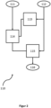
- the method step 110 for the overall flow forecast in which the forecast overall flow setpoint 116 is determined, is in an exemplary embodiment in figure 2 shown schematically.
- FIG 2 shows a schematic of an exemplary sequence of method step 110 for the overall flow forecast.
- the input variables for the total flow prognosis are the pressure 111 specified for ventilation and the current ventilation situation 112.
- the ventilation situation 112 can on the one hand reflect settings/parameters for ventilation of the patient and on the other hand patient-related factors, for example the physiology of the patient, be included. Ventilation settings/parameters can be pressures (IPAP, EPAP, PEEP, etc.), flows, volumes, ventilation times, ventilation mode (CPAP, APAP, BiLevel, etc.), respiratory rates, etc.
- Patient-related factors, such as the patient's physiology include age, height, weight, gender, diseases, etc.
- the patient flow model 114 is parameterized by, among other things, evaluating the parameters of the previous breaths. For example, the profile of the patient parameters from the pressure and flow are estimated or determined via the RC substitute model 113 . Together with at least the specified pressure 111, it is determined in a patient flow model 114, for example, which gas flow should reach the patient.
- the patient is initially represented as the starting point via the exemplary RC substitute model 113 and a patient flow is determined in the following patient flow model 114 together with the ventilation pressure 111 set, among other things.
- the parameters of the penultimate breath are used and the last breath is evaluated.
- the predicted total flow 116 is calculated via a calculation 115 from the calculations of the patient flow model 114 and the current ventilation situation 112 .
- the parameters/factors of the current ventilation situation 112, which are included in the patient flow model and directly in the calculation 115 of the predicted total flow 116, can be the same or different. Provision can be made for some parameters of the current ventilation situation 112 to be included both in the patient flow model 114 and directly in the calculation 115 of the predicted total flow 116 . Some parameters of the current ventilation situation 112 can only go directly into the patient flow model 114 or the calculation 115 .
- the predicted total flow target value 116 reflects the total flow that is delivered to/from the patient. For example, the flow of the ambient air drawn in plus the gas flow 146.
- the method step 120 of flow scaling is in an exemplary embodiment in figure 3 shown schematically.
- a scaling step 126 the predicted total flow setpoint 116 is scaled. Inspiration data 121 and expiration data 122 of the patient 212 are used as a further input variable for the scaling 126 .
- a scaling factor or a scaling function is determined, with which the predicted total flow target value 116 is scaled.
- a switch 125 is used to switch between scaling for inspiration and expiration.
- the inspiration data 121 or expiration data 122 are calculated values, for example, which take into account at least one ratio between an intended inspiration or expiration volume and the inspiration or expiration volume actually applied. Optionally, this ratio is averaged over several breaths and, if necessary, weighted. A weighting can take place, for example, on the basis of how up-to-date the breaths are, for example more recent breaths are weighted more highly than breaths that lie further in the past. In some embodiments, the determination of the scaling factor or the scaling function can also take into account other data and influences.
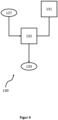
- the method step 130 for determining the scaled, predicted gas flow setpoint value 133 is shown schematically.
- the method step 130 also includes the optional consideration of the rebreathing volume V_Return.
- the rebreathing volume V_schreib is included in the calculation 132 of the scaled, predicted gas flow setpoint value 133 via the determination 131 of a mean concentration mcO2% of the first gas (for example oxygen) in the second gas/gas mixture.
- the second gas is, for example, a gas mixture, which may include a certain concentration of the first gas.
- the gas mixture (second gas) breathing gas, which contains a certain concentration of oxygen (first gas) can be cited here as an example.
- the mean concentration mcO2% takes into account both the freshly drawn in ambient air and the rebreathed respiratory gas.
- the aim of considering the rebreathing volume V_Return is that a total concentration of the first gas in the second gas can be set.
- the concentrations of the first gas in the first gas (100%) and in the second gas are at least approximately known.
- the rebreathing ie the backflow of the gas mixture produced from the first and second gas, changes the concentration of the first gas in the gas mixture to which the first gas is to be admixed.
- the target concentration of the first gas (here: oxygen) in the second gas here: the respiratory gas
- the target concentration of the first gas here: oxygen
- the respiratory gas can also be used.
- the specified 21% refers to the oxygen content of the ambient air.
- the oxygen content of the ambient air sucked in is measured and the measured value is replaced instead of the specified 21%. If the proposed method is intended to regulate the flow of a gas other than oxygen, the values must be adjusted accordingly.
- a supplementary or alternative approach can also be that a concentration of the first gas that is not constant, but rather a high and then decreasing one, is used as the target variable. For example, the concentration in the rebreathing volume can be smaller and the first gas can be added in accordance with the target concentration in the next breath.
- At least the target concentration of the first gas in the respiratory gas is included in the calculation 132 of the scaled, predicted gas flow setpoint 133.
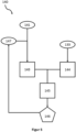
- the method step 140 for controlling 145 the gas valve is in an exemplary embodiment in figure 5 shown schematically.
- the exemplary embodiment in figure 5 also includes the determination of the manipulated variable for control 145 of the gas valve 203 from the correction controller component 143 and the feedforward component 144.
- One of the input variables for the feedforward component 144 is the scaled, predicted gas flow setpoint 133, which, for example, in method step 130 is determined.
- the actual gas flow value 147 is compared with the specified gas flow setpoint value 141 for the correction control component 143 . Corresponds to the actual If the actual gas flow value 147 corresponds to the specified gas flow setpoint value 141, then the correction controller component 143 becomes zero, so no deviation can be determined.
- the correction controller component 143 is, for example, independent of the cause of a possible deviation, but only indicates whether and by how much the set gas flow setpoint value 141 and the actual gas flow value 147 differ from one another. In some specific embodiments, it can additionally be provided that an error analysis is carried out and the cause of the deviation is also included in the correction controller component 143 .
- a cause-independent correction is carried out via the correction controller component 143.
- an error analysis is also carried out and this influences the feedforward component 144 finds.
- the feedforward component 144 is designed in such a way that any faults and/or inaccuracies in the valve control can be included in advance.
- the feedforward component 144 can be determined on the basis of the specified gas flow setpoint value 141, which in turn is determined from a measured total flow.
- the feedforward component 144 is based on a predicted gas flow target value, for example a scaled, predicted gas flow target value 133. This can, for example, minimize the response time and/or improve the control quality.
- the feedforward portion 144 is determined in accordance with the known prior art.
- the feedforward component 144 can be determined, for example, using a model, such as an inverse system model, of the valve to be controlled or a characteristic curve of the valve. In some embodiments, a mixture of the shapes and/or other models and/or characteristics for determining the feedforward component 144 can also be provided.
- FIG figure 6 An exemplary embodiment of a ventilator 200 is shown schematically and greatly simplified in FIG figure 6 shown.
- the ventilator 200 is set up and configured, in particular by the control unit 214 and the calculation unit 213, to control a gas valve 203 via feedforward regulation.
- the ventilator 200 is designed and set up to monitor and at least partially analyze the breathing of the patient 212 .
- the ventilator 200 is set up to recognize the breathing phases (inspiration, expiration).
- the ventilator 200 can also be set up to to recognize various breathing situations such as apnea, snoring, breathing pauses, irregular breathing, weak breathing, etc. Provision can be made for the ventilator 200 to be set up to automatically set, at least in part, specific ventilation parameters such as pressure and/or flow and/or volume and/or frequency to support and/or specify breathing.
- the ventilator 200 is set up and designed to support the patient 212 in breathing at least in phases and/or to specify the breathing of the patient 212 .
- the ventilator 200 comprises at least two gas sources 201, 206.
- the gas sources 201, 206 are set up to provide the ventilator 200 with at least one gas or gas mixture.
- the gas source 201 represents an oxygen source.
- the oxygen source 201 comprises at least one connection for a compressed gas connection, such as an oxygen cylinder.
- the oxygen source 201 comprises an oxygen concentrator integrated into or connected to the ventilator 200 .
- a compressed gas source for example an oxygen bottle
- a pressure reducer to be arranged between the compressed gas source and the ventilator 200 .
- a pressure reducer from the oxygen source 201 can also be arranged in or on the ventilator 200 .
- the oxygen source 201 includes a filter.
- a pressure sensor 202 is pneumatically connected to the oxygen source 201 and is set up to measure the pressure of the oxygen supplied.
- the ventilator 200 is set up and configured to use the measured pressure of the pressure sensor 202 to draw conclusions about the filling level of the oxygen source 201 or a pressurized gas source connected thereto.
- a low level warning or alarm is provided via user interface 218 .
- the pressure sensor 202 is followed by a controllable valve 203, via which the oxygen flow 106 from the oxygen source 201 to the mixing area 205 is regulated.
- the valve 203 is controlled, for example, via the control unit 214 using the inventive method.
- a flow sensor 204 is arranged downstream of the valve 203 and is set up and configured to measure the flow of the oxygen stream.
- the at least second gas source 206 is designed, for example, as an intake area 206 for ambient air.
- the intake area 206 is optionally equipped with a filter which filters the ambient air. For example, pathogens and other contaminants are at least partially filtered out of the ambient air.
- the intake area 206 can include a gas delivery unit, which is designed to suck in ambient air. In the exemplary embodiment shown in FIG figure 5 the ambient air is sucked in by the blower 208 via the intake area 206 .
- the respirator 200 can also have a connection to a compressed gas source, such as a compressed air bottle.
- a flow sensor 207 is arranged downstream of the gas source 206 or the intake area 206 , which is designed and configured to measure the gas flow from the intake area 206 in the direction of the mixing area 205 .
- the ventilator 200 comprises a mixing area 205 in which the gas flow from the gas source 201 and from the gas source 206 come together and are at least partially mixed.
- the mixing area 205 is designed as a mixing chamber, which has a volume and optionally has specific structures that improve mixing of the two gases. Alternatively or additionally, it can also be provided that active mixing is provided, for example by rotors and/or swirlers.
- the mixing area 205 is implemented by simply combining the two gas paths from the gas sources 201, 206. For example, a Y-piece can be provided for this purpose.
- a controllable blower 208 is arranged downstream of the mixing area 205 and is designed and set up to convey the gas mixture, for example as respiratory gas, out of the mixing area 205 . It should be noted that in some situations the valve 203 is closed and no gas flows from the gas source 201 into the mixing area 205, so that the gas mixture or the breathing gas from the mixing area 205 may only come from the sucked gas/gas mixture from the Gas source / the intake area 206 is. In some embodiments, the fan 208 is also set up and configured to draw in ambient air via the intake area 206 . The blower 208 is set up to provide an adjustable pressure and/or flow of breathing gas—promoted from the mixing area 205.
- the oxygen content of the respiratory gas delivered is measured via the oxygen sensor 209 .
- the measured oxygen content can, for example, be included in the control of the valve 203, for example in order to be able to correct deviations from a target value.
- the ambient air can have a different oxygen concentration than the assumed 21%, so that although the correct oxygen flow 116 is set, the oxygen concentration in the breathing gas still does not correspond to the setpoint.
- a pressure sensor 210 is arranged, for example, after the oxygen sensor 209 and is set up to detect the breathing gas pressure of the breathing gas line behind the blower 208 .
- a flow sensor 211 is arranged after the pressure sensor 210, which is set up and designed to detect or measure the respiratory gas flow.
- the ventilator 200 is connected to the patient 212 via a hose system 219 and a patient interface (not shown), for example.
- a leakage system or a 2-hose system or a 1-hose-valve system can be used as the hose system 219 .
- the tube system and/or the patient interface has an intended leakage through which the breathing gas exhaled by the patient 212 can at least partially escape.
- part of the exhaled breathing gas is also conducted in the direction of the ventilator 200 . Provision can be made here for the volume of the patient interface and the tube system to be taken into account in such a way that the exhaled respiratory gas can essentially be prevented from penetrating into the ventilator 200 .
- an additional valve for example a non-return valve, is provided in the area where the hose system 219 is connected to the ventilator 200, which essentially prevents rebreathing into the ventilator 200.
- a valve near the patient is controlled by the ventilator 200 in such a way that the exhaled air can escape directly through the valve into the environment at least temporarily during the expiration of the patient.
- the ventilator 200 has separate inspiratory and expiratory branches (not shown) for use with a 2-hose system. Breathing gas is conveyed to the patient 212 via the inspiration branch during the inspiration of the patient 212 . During the expiration of the patient 212, the exhaled breathing gas is conducted through the ventilator 200 via the expiration branch and is conducted into the environment. In some embodiments, the exhaled Breathing gas filtered through a filter in the expiratory branch.
- a valve is arranged in the hose system 219, for example, which closes the inspiration branch during the expiration phase, so that no exhaled breathing gas can penetrate into the inspiration branch.
- the exhaled breathing gas is fed back through a second tube to an expiration branch in the ventilator 200 and is conducted through it, for example, into the ambient air. For example, due to valve delays, it can happen that a small part of the respiratory gas is pushed back within the inspiratory branch of the ventilator 200 . Essentially, however, exhaled breathing gas is prevented from reaching the inspiratory branch of the ventilator 200 .
- the ventilator 200 comprises at least one calculation unit 213, a control unit 214, a detection unit 215, a monitoring unit 216, a storage unit 217 and a user interface 218.
- Calculation unit 213 is set up and designed to use the manipulated variable for controlling gas valve 203 and/or feedforward component 144 and/or correction controller component 143 and/or the input variable, e.g. a predicted gas flow setpoint, for the feedforward component 144 to calculate.
- the calculation unit 213 is designed, for example, to carry out the method 100 at least partially. In some embodiments, the calculation unit 213 is set up to carry out the calculation steps of the method 100 and the control unit 214 to control the gas valve 203 based thereon. The calculation unit 213 is designed for this in a first method step 110 from the current ventilation situation 112 and a set ventilation pressure 111 (PressureSetpoint ) to predict/forecast a total flow setpoint 116 . In a further procedural step 120, the calculation unit 213 calculates a scaled total flow reference value 127 from the predicted total flow target value 116 and inspiration and expiration data 12. From the scaled total flow target value 127 and optionally including the rebreathing volume V_rück, the calculation unit determines in a further procedural step 130 a scaled, predicted gas flow setpoint 133.
- the calculation unit 213 first calculates a predicted gas flow target value from the predicted total flow target value 116 in method step 130, optionally including the rebreathing volume V_schreib. This predicted gas flow setpoint is then used instead of the total flow setpoint 116 in method step 120 as an input value for determining a scaled gas flow setpoint 133 (instead of a scaled total flow setpoint 127).
- Method step 120 and method step 130 can therefore be interchangeable, with a scaled total flow setpoint 127 and then the scaled gas flow setpoint 133 being determined first, depending on the sequence, or a predicted gas flow setpoint being first calculated from the predicted total flow setpoint 116, which is then scaled to obtain the scaled gas flow setpoint 133 .
- the scaled, predicted gas flow setpoint value 133 is then used as the input variable for the feedforward component 144 of the manipulated variable for controlling 145 the gas valve 203.
- the manipulated variable can be determined, for example, by the control unit 214 and/or by the calculation unit 213.
- the control unit 214 is set up to control the gas valve 203 using the manipulated variable determined from the feedforward component 144 and a correction controller component 143 .
- the one calculation also includes the determination of the manipulated variable for control 145 of the gas valve 203 .
- the method steps shown can therefore be carried out at least partially in a single calculation, with the individual method steps representing, for example, individual parts of an equation.
- the correction controller component 143 is based on a comparison of a set gas flow setpoint 141 and the actual, measured gas flow actual value 147.
- the gas flow actual value 147 is measured, for example, by the flow sensor 204 and detected by the detection unit 215.
- the control unit 214 is set up and designed to control at least the valve 203 . In some embodiments, the control unit 214 is also configured to control the fan 208 . Provision can also be made for the control unit 214 to be designed and set up to control the entire ventilator 200 . In some embodiments, it can alternatively or additionally be provided that separate control units are present for different functions and/or modules and/or components.
- the calculation unit 213 is at least partially integrated into the control unit 214 and/or the control unit 214 comprises the calculation unit 213 .
- the acquisition unit 215 is set up and designed to acquire the values measured by the sensors and, if necessary, to process them.
- the detection unit 215 is set up to receive and/or record a signal generated by the sensors, for example in the form of voltage and/or current and/or frequency.
- the detection unit 215 is also designed to convert the signals of the sensors into values.
- the monitoring unit 216 is set up and designed to detect (technical) problems of the ventilator 200 .
- Technical problems can be, for example, a low battery level, an error in the electronics, a defective battery, a defective component and/or module, a power failure, an accessory that is not working correctly, an implausible measured value or a deviation from a permitted temperature range.
- the monitoring unit 216 can also be designed to generate an alarm and/or a message when a technical problem is detected.
- the monitoring unit 216 is designed to detect a low fill level and/or an insufficient supply of an operating medium, for example a gas.
- the monitoring unit 216 is designed to be able to use a pressure of the gas source 201 of the first gas to detect whether the supply is decreasing and/or insufficient.
- the (intermediate) results of the calculation unit 213 and the measured values recorded by the recording unit 215 are stored and/or temporarily stored in the storage unit 217 .
- Intermediate storage means that the data is automatically deleted or released for overwriting after a certain period of time and/or an (automatically) executed action and/or an event.
- Data and/or information can be input and output via the user interface 218, for example a unit comprising input elements and output elements.
- settings for ventilation and for the configuration of the ventilator 200 can be made via the input elements.
- the output element for example a display, is set up to show information and data on the current ventilation and settings.
- the user interface 218 can also be used to trigger alarms and warnings regarding the functionality of the device and also for the ventilation of the patient 212 are issued. Specifications for ventilation, for example pressures, flow, volume, duration, program, can be entered via the user interface 218 .
- An (initial) target value for the oxygen concentration in the breathing gas can also be set. In some embodiments, the target value of the oxygen concentration in the respiratory gas is optionally automatically adjusted by the ventilator 200 during ventilation.
- an initial oxygen concentration is specified by a user and the ventilator 200 automatically adjusts the oxygen concentration during use. Provision can also be made, for example, for an oxygen concentration to be initially specified and for the ventilator 200 to automatically set the specified oxygen concentration only if, for example, the oxygen supply to the patient 212 can no longer be maintained at the preset value and/or the patient 212 is in a is oversupplied to a harmful degree. For this purpose, it can be provided, for example, that the ventilator 200 is supplied with data on the oxygen saturation of the blood of the patient 212 via a pulse oximeter.
- threshold values and limit values for example for minimum and maximum oxygen concentration, minimum and maximum oxygen flow, minimum and maximum breathing gas pressures, etc. can also be entered via the user interface.
- the threshold and limit values can also apply as alarm limits.
- the user interface 218 alternatively or additionally comprises an interface for connecting external display and/or input devices such as screens, keyboards and/or remote controls.
- an additional breathing gas humidifier optionally with breathing gas heating
- Provision can also be made, for example, for a nebulizer to be arranged in the ventilator 200 and/or to be connected to the ventilator 200 .
- an expiratory branch may also be provided along with appropriate valving and controls. The breathing gas exhaled by the patient 212 is routed to the ambient air in the ventilator 200 via such an expiration branch.
- one or more bypass valves can optionally be installed in the pneumatics of the Ventilation device 200 may be arranged, for example to enable the patient to breathe at least temporarily when there is no energy supply.
- a change in the gas flow through the use of a nebulizer and/or respiratory gas humidifier can be taken into account.
- the ventilator 200 can also have at least one interface for connecting to remote remote stations, for example for telemedicine.
- the ventilator 200 is designed as an anesthetic device.
- at least one, preferably additional, gas source is provided in such a way that an anesthetic gas is introduced into the respiratory gas via this source.
- the inventive control is used to control the flow of the anesthetic gas.
- the inventive controller is used in parallel for controlling the gas valve 203 for the first gas source 201 and also for controlling, for example, a further gas valve of the anesthetic gas source.
- control unit 214 is used separately, that is to say independently of a ventilator 200, in order to control a gas valve 203. Provision can also be made, for example, for the control unit 214 to be used to control a gas valve 203 in other contexts in which mixing of at least two gases is provided. The same applies to the procedure.
- the patient model 114 is replaced by a model of a consumer.
- inspiration can be viewed, for example, as delivery of the gas mixture to the consumer, with expiration being able to correspond, for example, to expulsion of the used or converted gas mixture.
Landscapes
- Health & Medical Sciences (AREA)
- Engineering & Computer Science (AREA)
- Biomedical Technology (AREA)
- Public Health (AREA)
- General Health & Medical Sciences (AREA)
- Heart & Thoracic Surgery (AREA)
- Hematology (AREA)
- Life Sciences & Earth Sciences (AREA)
- Animal Behavior & Ethology (AREA)
- Anesthesiology (AREA)
- Pulmonology (AREA)
- Veterinary Medicine (AREA)
- Emergency Medicine (AREA)
- Medical Informatics (AREA)
- Primary Health Care (AREA)
- Epidemiology (AREA)
- Physics & Mathematics (AREA)
- Surgery (AREA)
- Urology & Nephrology (AREA)
- Nuclear Medicine, Radiotherapy & Molecular Imaging (AREA)
- General Physics & Mathematics (AREA)
- Automation & Control Theory (AREA)
- Business, Economics & Management (AREA)
- General Business, Economics & Management (AREA)
- Data Mining & Analysis (AREA)
- Databases & Information Systems (AREA)
- Pathology (AREA)
- Measurement Of The Respiration, Hearing Ability, Form, And Blood Characteristics Of Living Organisms (AREA)
Abstract
Description
- Die Erfindung betrifft eine Steuereinheit und ein Verfahren zur Regelung des Gasflusses eines ersten Gases zur Beimischung zu einem zweiten Gas.
- In vielen Geräte, insbesondere in medizintechnischen Geräten, ist es vorgesehen, dass zwei Gase miteinander gemischt werden. Zum Teil kann es vorkommen, dass das zweite Gas ein Gasgemisch ist, welches bereits eine bestimmte Konzentration des ersten Gases umfasst. In der Regel werden der Fluss und damit die Menge zumindest eins der zu mischenden Gase (oder Gasgemische) durch ein Ventil geregelt bzw. erzeugt. In der Regel wird dabei ein Regelkreis oder Steuerkreis verwendet, wonach das Ventil anhand der Konzentration des ersten Gases, beispielsweise Sauerstoff, in dem entstehenden Gemisch gesteuert wird. Die Messung der Sauerstoffkonzentration ist in der Regel aber ungenau und langsam. Dabei ergeben sich zum Beispiel Probleme bei der Versorgung von Patienten mit der richtigen Menge an Sauerstoff zur richtigen Zeit. Auch treten Verzögerungen in der Einstellung der richtigen Konzentration auf.
- Aufgabe der vorliegenden Erfindung ist daher die Bereitstellung eines Verfahrens und einer Vorrichtung zur effizienten Regulierung der Gaszusammensetzung.
- Die Erfindung betrifft eine Steuereinheit für ein Beatmungsgerät, wobei die Steuereinheit dazu eingerichtet und ausgebildet ist, ein Verfahren zur Regelung eines Gasflusses zumindest eines ersten Gases zur Beimischung zu zumindest einem zweiten Gas auszuführen, wobei das Verfahren zumindest einen Verfahrensschritt einer Steuerung eines Gasventils umfasst, wobei zumindest eine Stellgröße für die Steuerung des Gasventils aus zumindest einem Korrekturregler-Anteil und zumindest einem Feedforward-Anteil bestimmt wird, dadurch gekennzeichnet, dass die Eingangsgröße des Feedforward-Anteils ein prognostizierter Gasfluss-Sollwert des ersten Gases ist.
- In manchen Ausführungsformen kennzeichnet die Steuereinheit, dass das Verfahren ferner umfasst: einen ersten Verfahrensschritt der Gesamtfluss-Prognose; einen zweiten Verfahrensschritt zur Fluss-Skalierung; einen dritten Verfahrensschritt zur Bestimmung eines prognostizierten Gasfluss-Sollwerts und/oder eines skalierten, prognostizierten Gasfluss-Sollwerts.
- In manchen Ausführungsformen kennzeichnet die Steuereinheit, dass in dem ersten Verfahrensschritt ausgehend von einem eingestellten Druckwert und einer Beatmungssituation ein prognostizierter Gesamtfluss-Sollwert des Gasgemisches der zumindest zwei Gase bestimmt wird. In manchen Ausführungsformen kennzeichnet die Steuereinheit, dass der erste Verfahrensschritt ein Patientenfluss-Modell umfasst, wobei der eingestellte Druckwert und die Beatmungssituation zumindest teilweise in das Patientenfluss-Modell eingehen und wobei in eine Berechnung des prognostizierten Gesamtfluss-Sollwertes das Ergebnis des Patientenfluss-Modells sowie zumindest teilweise die Beatmungssituation eingehen. In manchen Ausführungsformen kennzeichnet die Steuereinheit, dass im ersten Verfahrensschritt über ein Patientenmodell, insbesondere in Form eines RC-Ersatzmodells, aus der Beatmungssituation Ausgangswerte für das Patientenfluss-Modell bestimmt werden.
- In manchen Ausführungsformen kennzeichnet die Steuereinheit, dass in dem zweiten Verfahrensschritt aus dem prognostizierten Gesamtfluss-Sollwert allein oder aus dem prognostizierten Gesamtfluss-Sollwert zusammen mit dem prognostizierten Gasfluss-Sollwert ein skalierter, prognostizierter Gesamtfluss-Sollwert und/oder der skalierte, prognostizierte Gasfluss-Sollwert berechnet wird. In manchen Ausführungsformen kennzeichnet die Steuereinheit, dass in dem zweiten Verfahrensschritt aus dem prognostizierten Gasfluss-Sollwert ein skalierter, prognostizierter Gesamtfluss-Sollwert und/oder der skalierte, prognostizierte Gasfluss-Sollwert berechnet wird. In manchen Ausführungsformen kennzeichnet die Steuereinheit, dass der zweite Verfahrensschritt eine Skalierung umfasst, wobei für die Inspiration und Exspiration separate Skalierungsfaktoren und/oder Skalierungsfunktionen bestimmt werden und je nach Inspiration oder Exspiration über einen Schalter zwischen den Skalierungsfaktoren und/oder Skalierungsfunktionen umgeschaltet wird. In manchen Ausführungsformen kennzeichnet die Steuereinheit, dass zur Bestimmung der Skalierungsfaktoren und/oder der Skalierungsfunktionen zumindest ein Vergleich zwischen einem vorgesehenen Inspirations- oder Exspirationsvolumen und einem tatsächlich applizierten Inspirations- oder Exspirationsvolumen berücksichtigt wird.
- In manchen Ausführungsformen kennzeichnet die Steuereinheit, dass der dritte Verfahrensschritt eine Berechnung des prognostizierten Gasfluss-Sollwerts aus dem prognostizierten Gesamtfluss-Sollwert umfasst. In manchen Ausführungsformen kennzeichnet die Steuereinheit, dass der dritte Verfahrensschritt die Bestimmung einer mittleren Konzentration mc02% des ersten Gases im zweiten Gas umfasst, wobei bei der Bestimmung der mittleren Konzentration mcO2% des ersten Gases ein Rückatemvolumen miteinbezogen wird. In manchen Ausführungsformen kennzeichnet die Steuereinheit, dass im dritten Verfahrensschritt die bestimmte mittlere Konzentration mcO2% des ersten Gases mit in die Bestimmung des prognostizierten Gasfluss-Sollwertes einbezogen wird.
- In manchen Ausführungsformen kennzeichnet die Steuereinheit, dass die Eingangsgröße für den Feedforward-Anteil zur Bestimmung der Stellgröße zur Steuerung des Gasventils der skalierte, prognostizierte Gasfluss-Sollwert ist, optional mit Berücksichtigung des Rückatemvolumens.
- In manchen Ausführungsformen kennzeichnet die Steuereinheit, dass die Eingangsgröße für den Korrekturregler-Anteil zumindest einen Parameter umfasst, welcher eine Abweichung eines durch zumindest einen Flusssensor bestimmten Gasfluss-Istwerts von einem vorgegebenen Gasfluss-Sollwert beschreibt.
- In manchen Ausführungsformen kennzeichnet die Steuereinheit, dass der Korrekturregler-Anteil der Stellgröße zur Steuerung des Gasventils Null wird, wenn der Gasflusswert dem Gasfluss-Sollwert entspricht.
- In manchen Ausführungsformen kennzeichnet die Steuereinheit, dass das erste Gas Sauerstoff ist und das zweite Gas Umgebungsluft oder Druckluft/Pressluft oder ein Gasgemisch aus Umgebungsluft und/oder Druckluft/Pressluft und/oder einem zumindest teilweise zurückgeatmeten Atemgas ist.
- In manchen Ausführungsformen kennzeichnet die Steuereinheit, dass die Steuereinheit dazu ausgebildet ist, das Rückatemvolumen anhand von Messdaten zumindest eines Flusssensors zu berechnen
- In manchen Ausführungsformen kennzeichnet die Steuereinheit, dass im ersten Verfahrensschritt aus zumindest einer Beatmungssituation, einem eingestellten Druckwert und zumindest teilweise über ein Patientenfluss-Modell ein prognostizierter Gesamtfluss-Sollwert berechnet wird; im zweiten Verfahrensschritt aus dem prognostizierten Gesamtfluss-Sollwert sowie Inspirationsdaten und Exspirationsdaten über eine Skalierung ein skalierter prognostizierter Gesamtfluss-Sollwert bestimmt wird, wobei die Skalierung auf die jeweilige Atemphase angepasst wird; im dritten Verfahrensschritt ein skalierter prognostizierter Gasfluss-Sollwert aus dem skalierten prognostizierten Gesamtfluss-Sollwert und einer, mit einem Rückatemvolumen bestimmten, mittleren Konzentration mcO2% des ersten Gases bestimmt wird; in einem vierten Verfahrensschritt die Eingangsgröße für den Feedforward-Anteil der skalierte prognostizierte Gasfluss-Sollwert ist.
- Die Erfindung betrifft auch ein Beatmungsgerät umfassend zumindest eine Steuereinheit wie zuvor beschrieben.
- Die Erfindung betrifft ferner ein Verfahren zur Regelung eines Gasflusses zumindest eines ersten Gases zur Beimischung zu zumindest einem zweiten Gas, wobei das Verfahren zumindest einen Verfahrensschritt einer Steuerung eines Gasventils umfasst, wobei zumindest eine Stellgröße für die Steuerung des Gasventils aus zumindest einem Korrekturregler-Anteil und zumindest einem Feedforward-Anteil bestimmt wird. Das Verfahren kennzeichnet, dass die Eingangsgröße des Feedforward-Anteils ein prognostizierter Gasfluss-Sollwert des ersten Gases ist.
- In manchen Ausführungsformen kennzeichnet das Verfahren, dass zumindest einen Verfahrensschritt der Gesamtfluss-Prognose; einen Verfahrensschritt zur Fluss-Skalierung; einen Verfahrensschritt zur Bestimmung eines prognostizierten Gasfluss-Sollwerts und/oder skalierten, prognostizierten Gasfluss-Sollwerts; und einen Verfahrensschritt zur Steuerung des Gasventils umfasst.
- In manchen Ausführungsformen kennzeichnet das Verfahren, dass zumindest einen Verfahrensschritt der Gesamtfluss-Prognose umfasst, wobei ausgehend von einem eingestellten Druckwert und einer Beatmungssituation ein prognostizierter Gesamtfluss-Sollwert des Gasgemisches der zumindest zwei Gase bestimmt wird.
- In manchen Ausführungsformen kennzeichnet das Verfahren, dass der Verfahrensschritt der Gesamtfluss-Prognose ein Patientenflussmodell umfasst, wobei der eingestellte Druckwert und die Beatmungssituation zumindest teilweise in das Patientenflussmodell eingehen und wobei in die Berechnung des prognostizierten Gesamtfluss-Sollwertes das Ergebnis des Patientenflussmodells sowie zumindest teilweise die Beatmungssituation eingehen.
- In manchen Ausführungsformen kennzeichnet das Verfahren, dass im Verfahrensschritt über ein Patientenmodell aus der Beatmungssituation Ausgangswerte für das Patientenflussmodell bestimmt werden. In manchen Ausführungsformen kennzeichnet das Verfahren, dass das Patientenmodell in Verfahrensschritt ein RC-Ersatzmodell ist.
- In manchen Ausführungsformen kennzeichnet das Verfahren, dass das Verfahren zumindest einen Verfahrensschritt zur Fluss-Skalierung umfasst, wobei in dem Verfahrensschritt zur Fluss-Skalierung aus dem prognostizierten Gesamtfluss-Sollwert und/oder einem prognostizierten Gasfluss-Sollwert ein skalierter, prognostizierter Gesamtfluss-Sollwert und/oder ein skalierter, prognostizierter Gasfluss-Sollwert berechnet wird.
- In manchen Ausführungsformen kennzeichnet das Verfahren, dass der Verfahrensschritt eine Skalierung umfasst, wobei für die Inspiration und Exspiration separate Skalierungsfaktoren und/oder Skalierungsfunktionen bestimmt werden und je nach Inspiration oder Exspiration über einen Schalter zwischen den Skalierungsfaktoren und/oder Skalierungsfunktionen umgeschaltet wird. In manchen Ausführungsformen kennzeichnet das Verfahren, dass zur Bestimmung der Skalierungsfaktoren und/oder Skalierungsfunktionen zumindest ein Vergleich zwischen den vorgesehen Inspirations- bzw. Exspirationsvolumen und den tatsächlich applizierten Inspirations- bzw. Exspirationsvolumen berücksichtigt werden.
- In manchen Ausführungsformen kennzeichnet das Verfahren, dass der Verfahrensschritt zur Bestimmung eines prognostizierten Gasfluss-Sollwerts die Berechnung eines prognostizierten Gasfluss-Sollwerts aus einem prognostizierten Gesamtfluss-Sollwert umfasst.
- In manchen Ausführungsformen kennzeichnet das Verfahren, dass der Verfahrensschritt die Bestimmung einer mittleren Konzentration mcO2% des ersten Gases im zweiten Gas umfasst, wobei bei der Bestimmung der mittleren Konzentration mcO2% des ersten Gases ein Rückatemvolumen miteinbezogen wird. In manchen Ausführungsformen kennzeichnet das Verfahren, dass im Verfahrensschritt die bestimmte mittlere Konzentration mcO2% des ersten Gases mit in die Bestimmung des prognostizierten Gasfluss-Sollwertes einbezogen wird.
- In manchen Ausführungsformen kennzeichnet das Verfahren, dass im Verfahrensschritt der skalierte, prognostizierte Gasfluss-Sollwert bestimmt wird.
- In manchen Ausführungsformen kennzeichnet das Verfahren, dass im Verfahrensschritt die Eingangsgröße für den Feedforward-Anteil zur Bestimmung der Stellgröße zur Steuerung des Gasventils der skalierte, prognostizierte Gasfluss-Sollwert ist, optional mit Berücksichtigung des Rückatemvolumens V_Rück.
- In manchen Ausführungsformen kennzeichnet das Verfahren, dass die Eingangsgröße für den Korrekturregler-Anteil zumindest einen Parameter umfasst, welcher die Abweichung des Gasflusswerts vom Gasfluss-Sollwert beschreibt.
- In manchen Ausführungsformen kennzeichnet das Verfahren, dass der Korrekturregler-Anteil der Stellgröße zur Steuerung des Gasventils Null wird, wenn der Gasflusswert dem Gasfluss-Sollwert entspricht.
- In manchen Ausführungsformen kennzeichnet das Verfahren, dass der Verfahrensschritt zur Fluss-Skalierung und der Verfahrensschritt zur Bestimmung eines prognostizierten Gasfluss-Sollwertes vertauschbar sind, wobei in dem Verfahrensschritt der prognostizierte Gasfluss-Sollwert berechnet wird, wenn der Verfahrensschritt auf den Verfahrensschritt folgt oder der skalierte, prognostizierte Gasfluss-Sollwert bestimmt wird, falls der Verfahrensschritt auf den Verfahrensschritt folgt.
- In manchen Ausführungsformen kennzeichnet das Verfahren, dass das erste Gas Sauerstoff ist und das zweite Gas Umgebungsluft oder Druckluft/Pressluft und oder ein Gasgemisch aus Umgebungsluft und/oder Druckluft/Pressluft und/oder einem zumindest teilweise zurückgeatmeten Atemgas ist.
- Die Erfindung betrifft ferner ein Verfahren zur Regelung des Gasflusses zumindest eines ersten Gases zur Beimischung zu zumindest einem zweiten Gas, wobei das Verfahren zumindest einen Verfahrensschritt einer Steuerung eines Gasventils umfasst, wobei zumindest eine Stellgröße für die Steuerung des Gasventils aus zumindest einem Korrekturregler-Anteil und zumindest einem Feedforward-Anteil bestimmt wird. Das Verfahren kennzeichnet ferner, dass
- a. in einem ersten Verfahrensschritt aus zumindest einer Beatmungssituation, einem eingestellten Druckwert und zumindest teilweise über ein Patientenflussmodell eine prognostizierter Gesamtfluss-Sollwert berechnet wird;
- b. in einem zweiten Verfahrensschritt aus dem Gesamtfluss-Sollwert sowie Inspirationsdaten und Exspirationsdaten über eine Skalierung ein skalierter prognostizierter Gesamtfluss-Sollwert bestimmt wird, wobei die Skalierung auf die jeweilige Atemphase angepasst wird;
- c. in einem dritten Verfahrensschritt ein skalierter prognostizierter Gasfluss-Sollwert aus dem skalierten prognostizierten Gesamtfluss-Sollwert und einer, mit einem Rückatemvolumen V_Rück bestimmten, mittleren Konzentration mcO2% des ersten Gases bestimmt wird;
- d. in einem der Verfahrensschritt der Steuerung des Gasventils ist, wobei die Eingangsgröße für den Feedforward-Anteil der skalierte prognostizierte Gasfluss-Sollwert aus dem dritten Verfahrensschritt ist.
- Die Steuereinheit ist dazu eingerichtet und ausgebildet, ein Verfahren zur Regelung eines Gasflusses zumindest eines ersten Gases zur Beimischung zu zumindest einem zweiten Gas auszuführen, wobei das Verfahren zumindest einen Verfahrensschritt einer Steuerung eines Gasventils umfasst, wobei zumindest eine Stellgröße für die Steuerung des Gasventils aus zumindest einem Korrekturregler-Anteil und zumindest einem Feedforward-Anteil bestimmt wird, dadurch gekennzeichnet, dass die Eingangsgröße des Feedforward-Anteils ein prognostizierter Gasfluss-Sollwert des ersten Gases ist.
- In manchen Ausführungsformen kennzeichnet die Steuereinheit, dass die Steuereinheit eine Berechnungseinheit umfasst, wobei die Berechnungseinheit dazu eingerichtet und ausgebildet ist, den prognostizierten Gasfluss-Sollwert eines ersten Gases aus einem prognostizierten Gesamtfluss-Sollwert zu bestimmen.
- In manchen Ausführungsformen kennzeichnet die Steuereinheit, dass die Berechnungseinheit dazu eingerichtet und ausgebildet ist, den prognostizierten Gesamtfluss-Sollwert aus einem eingestellten Druckwert und einer Beatmungssituation zu bestimmen.
- Die Erfindung betrifft auch ein Beatmungsgerät, wobei das Beatmungsgerät ein Gasventil und eine Steuereinheit umfasst, wobei die Steuereinheit dazu eingerichtet und ausgebildet ist das zuvor beschriebene Verfahren auszuführen.
- In manchen Ausführungsformen kennzeichnet das Beatmungsgerät, dass das Beatmungsgerät zumindest einen Flusssensor umfasst, wobei die Steuereinheit dazu eingerichtet und ausgebildet ist, das Rückatemvolumen V_Rück anhand der Messdaten zumindest eines Flusssensors zu berechnen.
- In manchen Ausführungsformen kennzeichnet das Beatmungsgerät, dass die Steuereinheit dazu eingerichtet und ausgebildet ist, aus einem Vergleich eines vorgegebenen Gasfluss-Sollwerts und einem durch einen Flusssensor bestimmten Gasflusswerts des Gasflusses des ersten Gases den Korrekturregler-Anteil der Stellgröße zur Steuerung des Gasventils zu bestimmen.
- In manchen Ausführungsformen kennzeichnet das Beatmungsgerät, dass die Steuereinheit dazu eingerichtet und ausgebildet ist das Gasventil anhand einer Stellgröße zu steuern, wobei die Stellgröße aus einem Feedforward-Anteil und einem Korrekturregler-Anteil besteht und wobei der Feedforward-Anteil als Eingangsgröße den prognostizierten Gasfluss-Sollwert des ersten Gases hat.
- In manchen Ausführungsformen kennzeichnet das Beatmungsgerät, dass das Beatmungsgerät und/oder die Steuereinheit eine Berechnungseinheit umfasst, wobei die Berechnungseinheit dazu eingerichtet und ausgebildet ist, den prognostizierten Gasfluss-Sollwert eines ersten Gases aus einem prognostizierten Gesamtfluss-Sollwert zu bestimmen.
- In manchen Ausführungsformen kennzeichnet das Beatmungsgerät, dass die Berechnungseinheit dazu ausgebildet ist aus einem eingestellten Druckwert und einer Beatmungssituation den prognostizierten Gesamtfluss-Sollwert zu bestimmen.
- In manchen Ausführungsformen kennzeichnet das Beatmungsgerät, dass die Berechnungseinheit dazu eingerichtet und ausgebildet ist ein Patientenflussmodell in die Bestimmung des prognostizierten Gesamtfluss-Sollwertes einzubeziehen.
- In manchen Ausführungsformen kennzeichnet das Beatmungsgerät, dass die Berechnungseinheit dazu eingerichtet und ausgebildet ist, aus dem prognostizierten Gesamtfluss-Sollwert einen skalierten, prognostizierten Gesamtfluss-Sollwert und/oder einen skalierten, prognostizierten Gasfluss-Sollwert zu berechnen.
- In manchen Ausführungsformen kennzeichnet das Beatmungsgerät, dass die Berechnungseinheit dazu eingerichtet und ausgebildet ist, den prognostizierten Gesamtfluss-Sollwert je nach Atemphase zu skalieren.
- In manchen Ausführungsformen kennzeichnet das Beatmungsgerät, dass die Berechnungseinheit in die Berechnung des skalierten, prognostizierten Gasfluss-Sollwerts eine mittlere Umgebungsluftkonzentration des ersten Gases miteinbezogen wird, wobei die mittlere Umgebungsluftkonzentration des ersten Gases unter anderem über ein Rückatemvolumen V_Rück bestimmt wird.
- In manchen Ausführungsformen kennzeichnet das Beatmungsgerät, dass die Berechnungseinheit dazu eingerichtet und ausgebildet ist, das Rückatemvolumen V_Rück anhand der Messdaten zumindest eines Flusssensors zu berechnen.
- In manchen Ausführungsformen kennzeichnet das Beatmungsgerät, dass die Berechnungseinheit dazu eingerichtet und ausgebildet ist, aus einem Vergleich eines vorgegebenen Gasfluss-Sollwerts und einem durch einen Flusssensor bestimmten Gasflusswerts des Gasflusses des ersten Gases den Korrekturregler-Anteil der Stellgröße zur Steuerung des Gasventils zu bestimmen.
- In manchen Ausführungsformen ist die Steuereinheit dazu ausgebildet und eingerichtet, ein Verfahren zur Regelung des Gasflusses zumindest eines ersten Gases zur Beimischung zu zumindest einem zweiten Gas auszuführen, wobei das Verfahren zumindest einen Verfahrensschritt einer Steuerung eines Gasventils umfasst, wobei zumindest eine Stellgröße für die Steuerung des Gasventils aus zumindest einem Korrekturregler-Anteil und zumindest einem Feedforward-Anteil bestimmt wird, dadurch gekennzeichnet, dass
- a. in einem ersten Verfahrensschritt aus zumindest einer Beatmungssituation, einem eingestellten Druckwert und zumindest teilweise über ein Patientenflussmodell eine prognostizierter Gesamtfluss-Sollwert berechnet wird;
- b. in einem zweiten Verfahrensschritt aus dem Gesamtfluss-Sollwert sowie Inspirationsdaten und Exspirationsdaten über eine Skalierung ein skalierter prognostizierter Gesamtfluss-Sollwert bestimmt wird, wobei die Skalierung auf die jeweilige Atemphase angepasst wird;
- c. in einem dritten Verfahrensschritt ein skalierter prognostizierter Gasfluss-Sollwert aus dem skalierten prognostizierten Gesamtfluss-Sollwert und einer, mit einem Rückatemvolumen V_Rück bestimmten, mittleren Konzentratio des ersten Gases mcO2% bestimmt wird;
- d. der Verfahrensschritt der vierte Verfahrensschritt ist, wobei die Eingangsgröße für den Feedforward-Anteil der skalierte prognostizierte Gasfluss-Sollwert aus dem dritten Verfahrensschritt ist.
- Die vorgestellte Steuerung, das vorgestellte Verfahren sowie das vorgestellte Beatmungsgerät ist dazu konzipiert, eine Gesamtkonzentration eines spezifischen Gases in einem Gasgemisch zu erreichen. Dabei wird ein erstes Gas einem zweiten Gas bzw. einem Gasgemisch zugemischt, wobei das zweite Gas/Gasgemisch eine Konzentration des ersten Gases beinhaltet. Erreicht wird dies durch eine gezielte Steuerung eines Gasventils, welches einen Fluss des ersten Gases erzeugt, welches dem zweiten Gas beigemischt wird. In manchen Ausführungsformen ist vorgesehen, dass das Gasgemisch aus erstem und zweitem Gas zumindest teilweise zurückfließen kann. Es kann dabei vorgesehen sein, die Konzentration des ersten Gases in dem zurückfließenden Gas mit zu berücksichtigen und die Steuerung des Gasventils für den Fluss des ersten Gases entsprechend anzupassen.
- Es ist darauf hinzuweisen, dass die in den Ansprüchen einzeln aufgeführten Merkmale in beliebiger, technisch sinnvoller Weise miteinander kombiniert werden können und weitere Ausgestaltungen der Erfindung aufzeigen. Die Beschreibung charakterisiert und spezifiziert die Erfindung insbesondere im Zusammenhang mit den Figuren zusätzlich.
- Es sei ferner darauf hingewiesen, dass eine hierin verwendete, zwischen zwei Merkmalen stehende und diese miteinander verknüpfende Konjunktion "und/oder" stets so auszulegen ist, dass in einer ersten Ausgestaltung des erfindungsgemäßen Gegenstands lediglich das erste Merkmal vorhanden sein kann, in einer zweiten Ausgestaltung lediglich das zweite Merkmal vorhanden sein kann und in einer dritten Ausgestaltung sowohl das erste als auch das zweite Merkmal vorhanden sein können.
- Unter einem Beatmungsgerät ist jedwedes Gerät zu verstehen, welches einen Anwender oder Patienten bei der natürlichen Atmung unterstützt, die Beatmung des Anwenders bzw. Lebewesens (z.B. Patient und/oder Neugeborener und/oder Frühgeborene) übernimmt und/oder zur Atemtherapie dient und/oder anderweitig die Atmung des Anwenders bzw. Patienten beeinflusst. Darunter fallen zum Beispiel, aber nicht ausschließend, CPAP- sowie BiLevel-Geräte, Narkose- bzw. Anästhesiegeräte, Atemtherapiegeräte, (klinische, außerklinische oder Notfall-) Beatmungsgeräte, Highflow-Therapiegeräte und Hustenmaschinen. Beatmungsgeräte können auch als Diagnosegeräte für die Beatmung verstanden werden. Diagnosegeräte können dabei allgemein zur Erfassung von medizinischen und/oder atmungsbezogenen Parametern eines Lebewesens dienen. Darunter fallen auch Geräte, welche medizinische Parameter von Patienten in Kombination mit der Atmung oder ausschließlich die Atmung betreffend, erfassen und optional verarbeiten können.
- Als Patienteninterface kann, soweit nicht ausdrücklich anders beschrieben, jegliches Peripheriegerät verstanden werden, welches zur Interaktion, insbesondere zu Therapie-, Beatmungs- und/oder Diagnosezwecken, eines Beatmungsgeräts mit einem Lebewesen und andersrum gedacht ist. Insbesondere kann ein Patienteninterface als Maske eines Beatmungsgerätes bzw. eine mit dem Beatmungsgerät verbundene Maske verstanden werden. Diese Maske kann eine Full-Face Maske, also Nase und Mund umschließende, oder eine Nasenmaske, also eine nur die Nase umschließende Maske, sein. Auch Trachealtuben bzw. -kanülen und sogenannte Nasenbrillen können als Maske beziehungsweise Patienteninterface eingesetzt werden. In manchen Fällen kann das Patienteninterface auch ein einfaches Mundstück, beispielsweise ein Rohr, sein, durch welches das Lebewesen zumindest ausatmet und/oder einatmet.
- Die Verbindung zwischen Patienteninterface und Beatmungsgerät kann über eine Vielzahl verschiedener Verbindungs- bzw. Schlauchsysteme erfolgen. Beispielsweise kann ein Leckagesystem vorgesehen sein, bei welchem ausgeatmetes Atemgas durch eine gewollte Leckage am Patienteninterface und/oder dem Beatmungsschlauch entweichen kann. Auch kann ein 2-Schlauch-System vorgesehen sein, bei dem das ausgeatmete Atemgas durch einen Exspirationsschlauch in das Beatmungsgerät zurückgeführt wird, das Ausatemvolumen gegebenenfalls dort gemessen wird und durch das Beatmungsgerät in die Umgebungsluft entweichen kann. Über ein Ventil wird dabei im Wesentlichen verhindert, dass das ausgeatmete Atemgas in den Inspirationsschlauch gelangt. Auch kann vorgesehen sein, dass das Patienteninterface und Beatmungsgerät über ein 1-Schlauch-System mit Patientenventil verbunden sind, welches zum Beispiel über das Beatmungsgerät gesteuert wird. Zumindest während der Exspiration kann das Ventil so geschaltet werden, dass die Ausatemluft direkt aus dem Schlauchsystem in die Umgebungsluft entweichen kann.
- In der Beschreibung und den Ansprüchen werden die Begriffe Gas und Gasgemisch synonym verwendet. Insbesondere kann ein Gas auch ein Gasgemisch beschreiben. Insbesondere kann es sich bei dem zweiten Gas um ein Gasgemisch handeln. Das zweite Gas kann dabei beispielsweise die Umgebungsluft sein, welche angesaugt wird oder auch Druckluft/Pressluft, welche aus Gasflaschen oder einer Versorgungsleitung zugeführt wird. In manchen Ausführungsformen kann das zweite Gas auch eine Mischung aus der angesaugten Umgebungsluft bzw. der Druckluft/Pressluft zusammen mit einem zurückgeatmeten bzw. zurückfließenden Gasgemisch sein. Das zurückfließende Gasgemisch kann dabei eine Konzentration des ersten Gases aufweisen, welche von dem ursprünglich erzeugten Gasgemisch abweicht. In manchen Ausführungsformen handelt es sich bei dem ersten Gas um Sauerstoff und bei dem zweiten Gas um Umgebungsluft und/oder einem zurückfließenden Gasgemisch und/oder eine Mischung daraus.
- Es ist ferner darauf hinzuweisen, dass unter "prognostizierter Gasfluss-Sollwert" jede Art von prognostiziertem Gasfluss-Sollwert zu verstehen ist, soweit nicht eindeutig anders beschrieben. Insbesondere kann "prognostizierter Gasfluss-Sollwert" neben dem (nicht skalierten) prognostizierten Gasfluss-Sollwert auch einen skalierten prognostizierten Gasfluss-Sollwert umfassen. Ebenso ist gilt, dass unter "prognostizierter Gesamtfluss-Sollwert" jede Art von prognostiziertem Gesamtfluss-Sollwert zu verstehen ist, soweit nicht eindeutig anders beschrieben. Insbesondere kann "prognostizierter Gesamtfluss-Sollwert" neben dem (nicht skalierten) prognostizierten Gesamtfluss-Sollwert auch einen skalierten prognostizierten Gesamtfluss-Sollwert umfassen.
- Die Erfindung folgt dem Grundgedanken, die Eingangsgröße für den Feedforward-Anteil der Stellgröße zu ersetzen. Bei einer klassischen Feedforward-Regelung für den Gasfluss ist zumindest eine Eingangsgröße für den Feedforward-Anteil ein aus einem gemessenen Gesamtfluss berechneter Gasfluss-Sollwert. Dieser aus einem gemessenen Gesamtfluss berechnete Gasfluss-Sollwert wird durch einen prognostizierten Gasfluss-Sollwert ersetzt, welcher aus einem prognostizierten Gesamtfluss ermittelt wird.
- Gemäß dem erfinderischen Verfahren, welches zum Beispiel von dem erfinderischen Beatmungsgerät ausgeführt werden kann, wird die Konzentration eines ersten Gases, beispielsweise Sauerstoff, unter anderem durch eine Feedforward-Regelung des Gasflusses des ersten Gases geregelt. Ziel der Feedforward-Regelung ist es, den Gasfluss vorzubestimmen und passend auf den nächsten bzw. aktuellen Atemzug zu regeln. Neben dem Feedforward-Anteil ist auch ein Korrekturregler-Anteil, ähnlich eines Feedbacks, vorgesehen. Der Korrekturregler-Anteil basiert dabei auf einem Vergleich des tatsächlich gemessenen Gasflusses mit dem vorgesehenen Wert um so etwaige Ungenauigkeiten oder Abweichungen zu korrigieren, unabhängig von der Fehlerquelle. Kommt durch den Feedforward-Anteil ein Gasfluss zustande, welcher genau dem eingestellten Zielwert entspricht, so findet keine Korrekturregelung statt. Durch die Korrekturregelung können beispielsweise auch systematische Fehler der Feedforward-Regelung ausgeglichen werden. Weicht der resultierende Gasfluss aus der Feedforward-Regelung beispielsweise immer um einen bestimmten Prozentsatz von dem vorgegebenen Zielwert ab, kann dieser durch die Korrekturregelung ausgeglichen werden.
- Als Eingangsgröße zur Bestimmung des Feedforward-Anteils dient ein prognostizierter Gasfluss-Sollwert des zu regelnden Gases. Zur Bestimmung des prognostizierten Gasfluss-Sollwerts wird in einem ersten Verfahrensschritt ein Gesamtfluss-Sollwert des Atemgases prognostiziert. In die Prognose wird dabei die aktuelle Beatmungssituation mit einbezogen. Die Beatmungssituation kann dabei zum einen Einstellungen/Parameter zur Beatmung des Patienten wiederspiegeln und zum anderen können auch patientenbezogene Faktoren, zum Beispiel die Physiologie des Patienten, miteinbezogen werden. Neben der aktuellen Beatmungssituation wird in die Berechnung der Gesamtfluss-Prognose auch ein Patientenfluss-Modell einbezogen. Eingangsgrößen und/oder Faktoren für das Patientenfluss-Modell sind zumindest ein Teil der aktuellen Beatmungssituation sowie der vorgegebene (Beatmungs-)Druck. Um in das Patientenfluss-Modell einbezogen zu werden, wird die aktuelle Beatmungssituation beispielsweise über ein RC-Ersatzmodell umgewandelt.
- In manchen Ausführungsformen ist vorgesehen, dass durch die Regelung bzw. Steuerung des Gasflusses zum Einstellen der Gaskonzentration des ersten Gases auch durch die Ansteuerung des Gasventils auftretende Ungenauigkeiten kompensiert werden können. Dazu wird in einem weiteren Verfahrensschritt ein Korrekturfaktor bestimmt, welcher beispielsweise auf die Gesamtfluss-Prognose angewendet wird. Dieser Korrekturfaktor kann beispielsweise auch auf die Atemphase des Patienten - also Inspiration und Exspiration - angepasst sein. Zur Bestimmung des Korrekturfaktors kann vorgesehen sein, dass, optional über mehrere Atemzüge gemittelt, ein Verhältnis zwischen einer Volumenvorgabe und/oder einem erwarteten Volumen und dem tatsächlich gemessenen Volumen erstellt wird. Anhand diesen Verhältnisses wird für die jeweilige Atemphase ein Korrekturfaktor bestimmt, welcher auf die Gesamtfluss-Prognose anwendet wird.
- Es kann vorgesehen sein, dass der prognostizierte Gasfluss-Sollwert des zu regelnden ersten Gases anhand der mit dem Korrekturfaktor verrechneten Gesamtfluss-Prognose bestimmt wird. In manchen Ausführungsformen kann auch vorgesehen sein, dass zunächst der prognostizierte Flusswert des zu regelnden Gases aus der Gesamtfluss-Prognose bestimmt wird und dieser prognostizierte Flusswert dann über den Korrekturfaktor skaliert wird.
- In manchen Ausführungsformen ist in einem Verfahrensschritt vorgesehen, dass optional auch ein in das Beatmungsgerät zurückgeatmeter und/oder durch die Ausatmung des Patienten zurückgeschobener Volumenteil berücksichtigt wird. Dabei wird der zurückgeatmete Volumenanteil bei der Bestimmung des prognostizierten Flusswertes des zu regelnden Gases miteinbezogen. Dieser Verfahrensschritt kann parallel zu, vor oder nach dem Verfahrensschritt der Bestimmung des Korrekturfaktors erfolgen. In manchen Ausführungsformen ist vorgesehen, dass der Verfahrensschritt der Berücksichtigung des Rückatemvolumens nach dem Verfahrensschritt der Bestimmung des Korrekturfaktors erfolgt.
- In einer Ausführungsform ist der Verfahrensablauf so vorgesehen, dass in einem ersten Verfahrensschritt eine Gesamtfluss-Prognose durchgeführt wird. In einem zweiten Verfahrensschritt ist dann vorgesehen, dass ein Korrekturfaktor bestimmt wird, welcher mit der Gesamtfluss-Prognose verrechnet wird. In einem dritten Verfahrensschritt erfolgt eine optionale Bestimmung des Rückatemvolumens. Danach erfolgt die Bestimmung des prognostizierten Gasflusses des zu regelnden Gases, optional unter Einbezug des Rückatemvolumens. Der prognostizierte Gasfluss des zu regelnden Gases wird dann als Eingangsgröße zur Feedforward-Regelung des Gasflusses genutzt. Zusammen mit einer Korrekturreglung wird ein Steuersignal für die Ventilschaltung erzeugt, wodurch der tatsächliche Gasfluss geregelt bzw. erzeugt wird. Der gemessene tatsächliche Gasfluss ist dabei eine Größe, welche zur Korrekturregelung herangezogen wird.
- Die Erfindung wird anhand der
Figuren 1 bis 6 beispielhaft näher beschrieben. - Der Ablauf des Verfahrens 100 zur Regelung des Gasflusses 146 ist in
Figur 1 in einer schematischen Übersicht einer beispielhaften Ausführungsform dargestellt. Das Verfahren 100 umfasst dabei einen Verfahrensschritt 110 der Gesamtfluss-Prognose, einen Verfahrensschritt 120 der Fluss-Skalierung, einen Verfahrensschritt 130 der Bestimmung eines skalierten, prognostizierten Gasfluss-Sollwerts 133 mit optionaler Berücksichtigung des Rückatemvolumens sowie einen Verfahrensschritt 140 der Steuerung des Gasventils. Der Verfahrensschritt 140 der Steuerung des Gasventils umfasst dabei auch die Bestimmung der Stellgröße zur Steuerung des Gasventils aus einem Korrekturregler-Anteil und einem Feedforward-Anteil. - Das Verfahren 100 zur Regelung des Gasflusses 146 beruht auf einer Feedforward-Regelung, wobei die Eingangsgröße des Feedforward-Anteils der Stellgröße zur Steuerung des Gasventils ersetzt wird. Der Vorteil einer Feedforward-Regelung besteht dabei darin, dass die Regelung an einer reinen Steuerung vorbeigeht, sodass eine erhöhte Reaktionszeit, beispielsweise bei Gasflussänderungen, erreicht werden kann. Bei einer klassischen Feedforward-Regelung für den Gasfluss 146 kann zumindest eine Eingangsgröße für den Feedforward-Anteil ein aus einem gemessenen Gesamtfluss berechneter Gasfluss-Sollwert 141 sein. Dieser aus einem gemessenen Gesamtfluss berechnete Gasfluss-Sollwert 141 wird durch einen prognostizierten Gasfluss-Sollwert ersetzt, welcher aus einem prognostizierten Gesamtfluss-Sollwert 116 ermittelt wird. Die Bestimmung des prognostizierten Gesamtfluss-Sollwerts 116 erfolgt dabei beispielhaft in dem Verfahrensschritt 110 der Gesamtfluss-Prognose. Aus dem prognostizierten Gesamtfluss-Sollwert 116 wird in den Verfahrensschritten 120, 130 der prognostizierte Gasfluss-Sollwert bestimmt und skaliert um zu einem skalierten prognostizierten Gasfluss-Sollwert 133 zu gelangen. In manchen Ausführungsformen wird dabei zunächst der prognostizierte Gesamtfluss-Sollwert 116 skaliert und aus dem skalierten, prognostizierten Gesamtfluss-Sollwert 127 in Verfahrensschritt 130 der skalierte, prognostizierte Gasfluss-Sollwert 133 bestimmt. Alternativ oder ergänzend wird aus dem prognostizierten Gesamtfluss-Sollwert 116 direkt der prognostizierte Gasfluss-Sollwert bestimmt, welcher dann in Verfahrensschritt 130 dann entsprechend skaliert wird. Ist die optionale Berücksichtigung des Rückatemvolumens V_Rück vorgesehen, so wird V_Rück bereits vor der Skalierung in die Berechnung des prognostizierten Gasfluss-Sollwertes einbezogen. Optional wird dabei im Verfahrensschritt 130 der Bestimmung des skalierten, prognostizierten Gasfluss-Sollwerts 133 auch das Rückatemvolumen V_Rück mit einbezogen um zum entsprechend angepassten Gasfluss-Sollwert 133 zu gelangen. Der prognostizierte Gasfluss-Sollwert 133 dient in Verfahrensschritt 140 als Eingangsgröße für den Feedforward-Anteil der Stellgröße für die Steuerung des Gasventils.
- Der Verfahrensschritt 110 zur Gesamtfluss-Prognose, in welchem der prognostizierte Gesamtfluss-Sollwert 116 bestimmt wird, ist in einer beispielhaften Ausführungsform in
Figur 2 schematisch dargestellt. -
Figur 2 zeigt schematisch einen beispielhaften Ablauf des Verfahrensschrittes 110 zur Gesamtfluss-Prognose. Unteranderem sind die Eingangsgrößen zur Gesamtfluss-Prognose der zur Beatmung vorgegebene Druck 111 sowie die aktuelle Beatmungssituation 112. Die Beatmungssituation 112 kann dabei zum einen Einstellungen/Parameter zur Beatmung des Patienten wiederspiegeln und zum anderen können auch patientenbezogene Faktoren, zum Beispiel die Physiologie des Patienten, miteinbezogen werden. Einstellungen/Parameter zur Beatmung können etwa Drücke (IPAP, EPAP, PEEP, etc.), Flüsse, Volumina, Beatmungszeiten, Beatmungsmodus (CPAP, APAP, BiLevel, etc.), Atmungsfrequenzen, etc. sein. Patientenbezogene Faktoren, wie beispielsweise die Physiologie des Patienten, sind beispielsweise Alter, Größe, Gewicht, Geschlecht, Erkrankungen, etc. - Eine Möglichkeit, die aktuelle Beatmungssituation 112 zu beschreiben, ist die Modellierung des Patienten über ein RC-Ersatzmodell 113. Neben einem RC-Ersatzmodell können auch andere und/oder weitere Patientenmodelle eingesetzt werden, welche den Patienten beispielsweise genauer beschreiben. Die Parametrierung des Patientenfluss-Modell 114 erfolgt, indem unter anderem die Parameter der vorherigen Atemzüge bewertet werden. Über das RC-Ersatzmodell 113 werden beispielsweise der Verlauf der Patientenparameter aus dem Druck und Fluss geschätzt bzw. bestimmt. Zusammen mit zumindest dem vorgegebenen Druck 111 wird in einem Patientenfluss-Modell 114 zum Beispiel bestimmt, welcher Gasfluss beim Patienten ankommen soll. Über das beispielhafte RC-Ersatzmodell 113wird also beispielsweise zunächst der Patient als Ausgangspunkt dargestellt und in dem folgenden Patientenfluss-Modell 114 wird unter anderem zusammen mit dem eingestellten Beatmungsdruck 111 ein Patientenfluss bestimmt. Beispielhaft werden in dem Zusammenspiel zwischen dem RC-Ersatzmodell 113 und dem PatientenflussModell 114 die Parameter des vorletzten Atemzuges genutzt und den letzten Atemzug zu bewerten.
- Aus den Berechnungen des Patientenfluss-Modells 114 sowie der aktuellen Beatmungssituation 112 wird über eine Berechnung 115 der prognostizierte Gesamtfluss 116 berechnet. Die Parameter/Faktoren der aktuellen Beatmungssituation 112, welche in das Patientenfluss-Modell und direkt in die Berechnung 115 des prognostizierten Gesamtflusses 116 eingehen können dabei gleich oder unterschiedlich sein. Es kann vorgesehen sein, dass manche Parameter der aktuellen Beatmungssituation 112 sowohl in das Patientenfluss-Modell 114 als auch direkt in die Berechnung 115 des prognostizierten Gesamtflusses 116 eingehen. Manche Parameter der aktuellen Beatmungssituation 112 können auch nur in das Patientenfluss-Modell 114 oder die Berechnung 115 direkt eingehen.
- Der prognostizierte Gesamtfluss-Sollwert 116 gibt dabei den Gesamtfluss wieder, welcher zu/vom Patienten gefördert wird. Beispielsweise also den Fluss der angesaugten Umgebungsluft plus den Gasfluss 146.
- Der Verfahrensschritt 120 der Fluss-Skalierung ist in einer beispielhaften Ausführungsform in
Figur 3 schematisch dargestellt. In einem Skalierungsschritt 126 wird der prognostizierte Gesamtfluss-Sollwert 116 skaliert. Als weitere Eingangsgröße für die Skalierung 126 werden dazu Inspirationsdaten 121 und Exspirationsdaten 122 des Patienten 212 herangezogen. In den Kalkulationsschritten 123, 124, welche jeweils einzeln für die Inspiration und Exspiration durchgeführt werden, wird ein Skalierungsfaktor bzw. eine Skalierungsfunktion bestimmt, mit welcher der prognostizierte Gesamtfluss-Sollwert 116 skaliert wird. Über einen Schalter 125 wird dabei je nach Atemphase zwischen Skalierung für die Inspiration bzw. Exspiration umgeschaltet. - Die Inspirationsdaten 121 bzw. Exspirationsdaten 122 sind dabei beispielsweise berechnete Werte, welche zumindest ein Verhältnis zwischen einem vorgesehenen Inspirations- bzw. Exspirationsvolumen und den tatsächlich applizierten Inspirations- bzw. Exspirationsvolumen berücksichtigt. Optional wird dieses Verhältnis über mehrere Atemzüge gemittelt und ggf. gewichtet. Eine Gewichtung kann beispielsweise anhand der Aktualität der Atemzüge erfolgen, beispielsweise werden aktuellere Atemzüge höher gewichtet als Atemzüge, welche weiter in der Vergangenheit liegen. In manchen Ausführungsformen kann die Bestimmung des Skalierungsfaktors bzw. der Skalierungsfunktion auch weitere Daten und Einflüsse berücksichtigt werden.
- In
Figur 4 ist eine beispielhafte Ausführungsform des Verfahrensschritt 130 zur Bestimmung des skalierten, prognostizierten Gasfluss-Sollwertes 133 schematisch dargestellt. Der Verfahrensschritt 130 umfasst in der bespielhaften Ausführungsform auch die optionale Berücksichtigung des Rückatemvolumens V_Rück. Das Rückatemvolumen V_Rück wird beispielhaft über die Bestimmung 131 einer mittleren Konzentration mcO2% des ersten Gases (beispielsweise Sauerstoff) im zweiten Gas/Gasgemisch in die Berechnung 132 des skalierten, prognostizierten Gasfluss-Sollwerts 133 einbezogen. Die mittlere Konzentration mcO2% des ersten Gases im zweiten Gas lässt sich am Beispiel Sauerstoff vereinfacht über die Formel
- In die Berechnung 132 des skalierten, prognostizierten Gasfluss-Sollwerts 133 wird beispielsweise neben der mittleren Umgebungsluftkonzentration mcO2% und dem skalierten, prognostizierten Gesamtfluss-Sollwert 127 zumindest auch die Zielkonzentration des ersten Gases in dem Atemgas einbezogen.
- Der Verfahrensschritt 140 zur Steuerung 145 des Gasventils ist in einer beispielhaften Ausführungsform in
Figur 5 schematisch dargestellt. Die beispielhafte Ausführungsform inFigur 5 umfasst auch die Bestimmung der Stellgröße zur Steuerung 145 des Gasventils 203 aus dem Korrekturregler-Anteil 143 und dem Feedforward-Anteil 144. Eine der Eingangsgrößen für den Feedforward-Anteil 144 ist dabei der skalierte, prognostizierte Gasfluss-Sollwert 133, welcher beispielhaft im Verfahrensschritt 130 bestimmt wird. - Für den Korrekturregelungs-Anteil 143 wird der tatsächliche Gasfluss-Istwert 147 mit dem vorgegebenen Gasfluss-Sollwert 141 abgeglichen. Entspricht der tatsächliche Gasfluss-Istwert 147 dem vorgegebenen Gasfluss-Sollwert 141 so wird der Korrekturregler-Anteil 143 Null, es ist also keine Abweichung festzustellen. Der Korrekturregler-Anteil 143 ist dabei beispielsweise unabhängig von der Ursache einer möglichen Abweichung, sondern gibt lediglich an, ob und um wie viel der eingestellte Gasfluss-Sollwert 141 und der tatsächliche Gasfluss-Istwert 147 voneinander abweichen. In manchen Ausführungsformen kann ergänzend vorgesehen sein, dass eine Fehleranalyse durchgeführt wird und auch die Ursache der Abweichung mit in den Korrekturregler-Anteil 143 einbezogen wird. Alternativ oder ergänzend kann vorgesehen sein, dass bei Abweichungen zwischen tatsächlichem Gasfluss-Istwert 147 und dem eingestellten Gasfluss-Sollwert 141 über den Korrekturregler-Anteil 143 eine Ursachen-unabhängige Korrektur vorgenommen wird gleichzeitig auch eine Fehleranalyse durchgeführt wird und diese Einfluss in den Feedforward-Anteil 144 findet.
- Der Feedforward-Anteil 144 ist so ausgelegt, dass etwaige Störungen und/oder Ungenauigkeiten der Ventilansteuerung bereits vorab einbezogen werden können. Bei einer regulären Feedforward-Regelung kann die Bestimmung des Feedforward-Anteils 144 anhand des vorgegebenen Gasfluss-Sollwertes 141, welcher wiederum aus einem gemessenen Gesamtfluss bestimmt wird, erfolgen. In dem beschriebenen Verfahren basiert der Feedforward-Anteil 144 hingegen auf einem prognostizierten Gasfluss-Sollwert, zum Beispiel einem skalierten, prognostizierten Gasfluss-Sollwert 133. Dadurch kann beispielsweise die Reaktionszeit minimiert und/oder die Regelgüte verbessert werden. Der Feedforward-Anteil 144 wird dabei entsprechend dem bekannten Stand der Technik bestimmt. Der Feedforward-Anteil 144 kann beispielswiese über ein Modell, etwa ein inverses Systemmodel, des zu steuernden Ventils oder einer Kennlinie des Ventils bestimmt werden. In manchen Ausführungsformen kann auch eine Mischung aus den Formen und/oder andere Modelle und/oder Kennlinien zur Bestimmung des Feedforward-Anteils 144 vorgesehen sein.
- Eine beispielhafte Ausführungsform eines Beatmungsgerätes 200 ist schematisch und stark vereinfacht in
Figur 6 dargestellt. Das Beatmungsgerät 200 ist dabei, insbesondere durch die Steuereinheit 214 und die Berechnungseinheit 213 dazu eingerichtet und ausgebildet ein Gasventil 203 über eine Feedforward-Regelung zu steuern. - Das Beatmungsgerät 200 ist dazu ausgebildet und eingerichtet, die Atmung des Patienten 212 zu überwachen und zumindest teilweise zu analysieren. Beispielsweise ist das Beatmungsgerät 200 dazu eingerichtet die Atemphasen (Inspiration, Exspiration) zu erkennen. Auch kann das Beatmungsgerät 200 dazu eingerichtet sein, verschiedene Atemsituationen wie etwa Apnoen, Schnarchen, Atemaussetzer, unregelmäßige Atmung, schwache Atmung, etc. zu erkennen. Es kann vorgesehen sein, dass das Beatmungsgerät 200 dazu eingerichtet ist zumindest teilweise bestimmte Beatmungsparameter wie Druck und/oder Fluss und/oder Volumen und/oder Frequenz zur Unterstützung und/oder Vorgabe der Atmung automatisch einzustellen. Das Beatmungsgerät 200 ist dazu eingerichtet und ausgebildet den Patienten 212 zumindest phasenweise bei der Atmung zu unterstützen und/oder die Atmung des Patienten 212 vorzugeben.
- Das Beatmungsgerät 200 umfasst zumindest zwei Gasquellen 201, 206. Die Gasquellen 201, 206 sind dazu eingerichtet dem Beatmungsgerät 200 jeweils zumindest ein Gas bzw. Gasgemisch zur Verfügung zu stellen.
- In der gezeigten, beispielhaften Ausführungsform stellt die Gasquelle 201 eine Sauerstoffquelle dar. Beispielhaft umfasst die Sauerstoffquelle 201 zumindest einen Anschluss für einen Druckgasanschluss, etwa eine Sauerstoffflasche. Es kann alternativ oder ergänzend auch vorgesehen sein, dass die Sauerstoffquelle 201 einen in das Beatmungsgerät 200 integrierten oder verbundenen Sauerstoffkonzentrator umfasst. Ist eine Druckgasquelle, zum Beispiel eine Sauerstoffflasche, mit der Sauerstoffquelle 201 des Beatmungsgeräts 200 verbunden, so kann vorgesehen sein, dass ein Druckminderer zwischen der Druckgasquelle und dem Beatmungsgerät 200 angeordnet ist. Alternativ oder ergänzend kann auch ein Druckminderer von der Sauerstoffquelle 201 in bzw. an dem Beatmungsgerät 200 angeordnet sein. Es kann zudem optional vorgesehen sein, dass die Sauerstoffquelle 201 einen Filter umfasst.
- Mit der Sauerstoffquelle 201 ist beispielhaft ein Drucksensor 202 pneumatisch verbunden, welcher dazu eingerichtet ist, den Druck des gelieferten Sauerstoffs zu messen. In manchen Ausführungsformen ist das Beatmungsgerät 200 dazu eingerichtet und ausgebildet anhand des gemessenen Drucks des Drucksensors 202 einen Rückschluss auf den Füllstand der Sauerstoffquelle 201 bzw. einer damit verbundenen Druckgasquelle zu ziehen. In manchen Ausführungsformen wird bei einem niedrigen Füllstand eine Warnung oder Alarm über die Benutzerschnittstelle 218 ausgegeben.
- Auf den Drucksensor 202 folgt ein steuerbares Ventil 203, über welches der Sauerstofffluss 106 von der Sauerstoffquelle 201 zum Mischbereich 205 geregelt wird. Die Steuerung des Ventils 203 erfolgt beispielhaft über die Steuereinheit 214 anhand des erfinderischen Verfahrens.
- Auf das Ventil 203 folgend ist ein Flusssensor 204 angeordnet, welcher dazu eingerichtet und ausgebildet ist, den Fluss des Sauerstoffstroms zu messen.
- Die zumindest zweite Gasquelle 206 ist in der gezeigten Ausführungsform beispielhaft als Ansaugbereich 206 für Umgebungsluft ausgebildet. Der Ansaugbereich 206 ist optional mit einem Filter ausgestattet, welcher die Umgebungsluft filtert. Beispielsweise werden so Pathogene und andere Verunreinigungen aus der Umgebungsluft zumindest teilweise herausgefiltert. In manchen Ausführungsformen kann der Ansaugbereich 206 über eine Gasfördereinheit umfassen, welche dazu ausgebildet ist, Umgebungsluft anzusaugen. In der beispielhaft dargestellten Ausführungsform in
Figur 5 wird die Umgebungsluft durch das Gebläse 208 über den Ansaugbereich 206 angesaugt. Alternativ oder ergänzend zu dem Ansaugbereich 206 kann das Beatmungsgerät 200 auch über eine Verbindung zu einer Druckgasquelle, etwa einer Druckluftflasche, aufweisen. Auf die Gasquelle 206 bzw. den Ansaugbereich 206 folgend ist ein Flusssensor 207 angeordnet, welcher dazu eingerichtet und ausgebildet ist, den Gasfluss aus dem Ansaugbereich 206 in Richtung Mischbereich 205 zu messen. - Das Beatmungsgerät 200 umfasst einen Mischbereich 205 in welchem der Gasfluss aus der Gasquelle 201 und aus der Gasquelle 206 zusammenkommen und zumindest teilweise durchmischt werden. In manchen Ausführungsformen ist der Mischbereich 205 als Mischkammer ausgebildet, welcher ein Volumen aufweist und optional über bestimmte Strukturen verfügt, welche eine Vermischung der beiden Gase verbessern. Es kann alternativ oder ergänzend auch vorgesehen sein, dass eine aktive Vermischung, beispielsweise durch Rotoren und/oder Verwirbler, vorgesehen ist. In manchen Ausführungsformen wird der Mischbereich 205 durch eine einfache Zusammenführung der beiden Gaswege von den Gasquellen 201, 206 umgesetzt. Beispielsweise kann dazu ein Y-Stück vorgesehen sein.
- Auf den Mischbereich 205 folgend ist ein steuerbares Gebläse 208 angeordnet, welches dazu ausgebildet und eingerichtet ist, das Gasgemisch, beispielsweise als Atemgas, aus dem Mischbereich 205 zu fördern. Dabei ist zu beachten, dass in manchen Situationen das Ventil 203 geschlossen ist und kein Gas aus der Gasquelle 201 in den Mischbereich 205 strömt, sodass das Gasgemisch bzw. das Atemgas aus dem Mischbereich 205 in unter Umständen ausschließlich aus dem angesaugten Gas/Gasgemisch aus der Gasquelle/dem Ansaugbereich 206 besteht. In manchen Ausführungsformen ist das Gebläse 208 auch dazu eingerichtet und ausgebildet, Umgebungsluft über den Ansaugbereich 206 anzusaugen. Das Gebläse 208 ist dazu eingerichtet einen einstellbaren Druck und/oder Fluss an Atemgas - gefördert aus dem Mischbereich 205 - bereitzustellen.
- Über den Sauerstoffsensor 209 wird der Sauerstoffgehalt des geförderten Atemgases gemessen. Der gemessene Sauerstoffgehalt kann beispielsweise in die Steuerung des Ventils 203 miteinbezogen werden, beispielsweise um Abweichungen gegenüber einem Sollwert korrigieren zu können. Beispielsweise kann die Umgebungsluft eine andere Sauerstoffkonzentration als die angenommenen 21% aufweisen, sodass zwar der richtige Sauerstofffluss 116 eingestellt wird, aber die Sauerstoffkonzentration im Atemgas dennoch nicht dem Sollwert entspricht.
- Beispielhaft auf den Sauerstoffsensor 209 folgend ist ein Drucksensor 210 angeordnet, welcher dazu eingerichtet ist, den Atemgasdruck der Atemgasleitung hinter dem Gebläse 208 zu erfassen. Beispielhaft auf den Drucksensor 210 folgend ist ein Flusssensor 211 angeordnet, welcher dazu eingerichtet und ausgebildet ist, den Atemgasfluss zu erfassen bzw. zu messen.
- Das Beatmungsgerät 200 ist beispielhaft über ein Schlauchsystem 219 und ein Patienteninterface (nicht dargestellt) mit dem Patienten 212 verbunden. Als Schlauchsystem 219 kann beispielsweise ein Leckagesystem oder ein 2-SchlauchSystem oder ein 1-Schlauch-Ventil-System genutzt werden. Bei einem Leckagesystem weist das Schlauchsystem und/oder das Patienteninterface eine gewollte Leckage auf, durch welche das vom Patienten 212 ausgeatmete Atemgas zumindest teilweise entweichen kann. Dabei wird in manchen Ausführungsformen ein Teil des ausgeatmeten Atemgases auch in Richtung des Beatmungsgerätes 200 geleitet. Es kann dabei vorgesehen sein, dass das Volumen des Patienteninterfaces und des Schlauchsystems so berücksichtigt werden, dass ein Eindringen des ausgeatmeten Atemgases in das Beatmungsgerät 200 im Wesentlichen verhindert werden kann. In manchen Ausführungsformen des Beatmungsgerätes 200 ist im Bereich des Anschlusses des Schlauchsystems 219 an das Beatmungsgerät 200 ein zusätzliches Ventil, beispielsweise ein Rückschlagventil, vorgesehen, welches eine Rückatmung in das Beatmungsgerät 200 im Wesentlichen verhindert. Bei einem 1-Schlauch-Ventil-System ist beispielsweise vorgesehen, dass ein patientennahes Ventil durch das Beatmungsgerät 200 so gesteuert wird, dass zumindest zeitweise während der Exspiration des Patienten die Ausatemluft direkt durch das Ventil in die Umgebung entweichen kann.
- Zur Verwendung eines 2-Schlauch-Systems verfügt das Beatmungsgerät 200 über separate Inspirations- und Exspirationszweige (nicht dargestellt). Über den Inspirationszweig wird während der Inspiration des Patienten 212 Atemgas zum Patienten 212 gefördert. Über den Exspirationszweig wird während der Exspiration des Patienten 212 das ausgeatmete Atemgas durch das Beatmungsgerät 200 geleitet und in die Umgebung geleitet wird. In manchen Ausführungsformen wird das ausgeatmete Atemgas über einen Filter im Exspirationszweig gefiltert. Bei der Verwendung eines 2-Schlauch-Systems ist beispielsweise im Schlauchsystem 219 ein Ventil angeordnet, welches während der Exspirationsphase den Inspirationszweig verschließt, sodass kein ausgeatmetes Atemgas in den Inspirationszweig dringen kann. Das ausgeatmete Atemgas wird dabei durch einen zweiten Schlauch zu einem Exspirationszweig in das Beatmungsgerät 200 zurückgeführt und durch diesen beispielsweise in die Umgebungsluft geleitet. Beispielsweise durch Ventilverzögerungen kann es vorkommen, dass ein geringer Teil des Atemgases innerhalb des Inspirationszweiges des Beatmungsgerätes 200 zurückgedrängt wird. Im Wesentlichen wird dabei aber verhindert, dass ausgeatmetes Atemgas den Inspirationszweig des Beatmungsgerätes 200 erreicht.
- Beispielhaft umfasst das Beatmungsgerät 200 zumindest eine Berechnungseinheit 213, eine Steuereinheit 214, eine Erfassungseinheit 215, eine Überwachungseinheit 216, eine Speichereinheit 217 und eine Benutzerschnittstelle 218.
- Die Berechnungseinheit 213 ist dazu eingerichtet und ausgebildet, die Stellgröße zur Steuerung des Gasventils 203 und/oder den Feedforward-Anteil 144 und/oder den Korrekturregler-Anteil 143 und/oder die Eingangsgröße, z.B. einen prognostizierten Gasfluss-Sollwert, für den Feedforward-Anteil 144 zu berechnen.
- Die Berechnungseinheit 213 ist beispielhaft dazu ausgebildet, das Verfahren 100 zumindest teilweise auszuführen. In manchen Ausführungsformen ist die Berechnungseinheit 213 dazu eingerichtet die Berechnungsschritte des Verfahrens 100 auszuführen und die Steuereinheit 214 die darauf basierende Steuerung des Gasventils 203. Die Berechnungseinheit 213 ist dazu ausgebildet in einem ersten Verfahrensschritt 110 aus der aktuellen Beatmungssituation 112 und einem eingestellten Beatmungsdruck 111 (PressureSetpoint) einen Gesamtfluss-Sollwert 116 vorherzusagen/zu prognostizieren. In einem weiteren Verfahrensschritt 120 berechnet die Berechnungseinheit 213 aus dem prognostizierten Gesamtfluss-Sollwert 116 sowie Inspirations- und Exspirationsdaten 12 einen skalierten Gesamtfluss-Sollwert 127. Aus dem skalierten Gesamtfluss-Sollwert 127 und unter optionaler Einbeziehung des Rückatemvolumens V_Rück bestimmt die Berechnungseinheit in einem weiteren Verfahrensschritt 130 einen skalierten, prognostizierten Gasfluss-Sollwert 133.
- In manchen Ausführungsformen kann vorgesehen sein, dass die Berechnungseinheit 213 zunächst im Verfahrensschritt 130 aus dem prognostizierten Gesamtfluss-Sollwert 116 einen prognostizierten Gasfluss-Sollwert, optional unter Einbeziehung des Rückatemvolumens V_Rück, berechnet. Dieser prognostizierte Gasfluss-Sollwert dient dann an der Stelle des Gesamtfluss-Sollwerts 116 in Verfahrensschritt 120 als Eingangswert für die Bestimmung eines skalierten Gasfluss-Sollwerts 133 (anstatt eines skalierten Gesamtfluss-Sollwerts 127). Der Verfahrensschritt 120 und der Verfahrensschritt 130 können also vertauschbar sein, wobei je nach Reihenfolge zunächst ein skalierter Gesamtfluss-Sollwert 127 und dann der skalierte Gasfluss-Sollwert 133 bestimmt werden oder zunächst aus dem prognostizierten Gesamtfluss-Sollwert 116 ein prognostizierter Gasfluss-Sollwert berechnet wird, welcher dann skaliert wird um den skalierten Gasfluss-Sollwert 133 zu erhalten.
- Der skalierte, prognostizierte Gasfluss-Sollwert 133 dient im Verfahrensschritt 140 dann als Eingangsgröße des Feedforward-Anteils 144 der Stellgröße zur Steuerung 145 des Gasventils 203. Die Stellgröße kann beispielsweise durch die Steuereinheit 214 und/oder durch die Berechnungseinheit 213 bestimmt werden. Die Steuereinheit 214 ist dabei dazu eingerichtet, anhand der aus dem Feedforward-Anteil 144 und einem Korrekturregler-Anteil 143 bestimmten Stellgröße das Gasventil 203 zu steuern.
- In manchen Ausführungsformen kann vorgesehen sein, dass in der Berechnungseinheit 213 die Verfahrensschritte 110, 120, 130 sowie die Bestimmung des Feedforward-Anteils 144 über eine einzelne Berechnung dargestellt wird, wobei die jeweiligen Eingangsgrößen als Variablen eingesetzt sind. In manchen Ausführungsformen kann auch vorgesehen sein, dass die eine Berechnung auch die Bestimmung der Stellgröße zur Steuerung 145 des Gasventils 203 umfasst. Die in
Figur 1 bis 5 dargestellten Verfahrensschritte können also zumindest teilweise in einer einzelnen Berechnung durchgeführt werden, wobei die einzelnen Verfahrensschritte beispielsweise einzelnen Teile einer Gleichung repräsentieren. - Der Korrekturregler-Anteil 143 basiert auf einem Vergleich eines eingestellten Gasfluss-Sollwerts 141 und dem tatsächlichen, gemessenen Gasfluss-Istwert 147. Der Gasfluss-Istwert 147 wird beispielsweise durch den Flusssensor 204 gemessenen und durch die Erfassungseinheit 215 erfasst.
- Die Steuereinheit 214 ist dazu eingerichtet und ausgebildet, zumindest das Ventil 203 zu steuern. In manchen Ausführungsformen ist die Steuereinheit 214 auch dazu eingerichtet das Gebläse 208 zu steuern. Es kann zudem vorgesehen sein, dass die Steuereinheit 214 dazu ausgebildet und eingerichtet ist, das gesamte Beatmungsgerät 200 zu steuern. In manchen Ausführungsformen kann alternativ oder ergänzend vorgesehen sein, dass für verschiedene Funktionen und/oder Module und/oder Komponenten separate Steuereinheiten vorhanden sind.
- Es kann in manchen Ausführungsformen vorgesehen sein, dass die Berechnungseinheit 213 zumindest teilweise in die Steuereinheit 214 integriert ist und/oder die Steuereinheit 214 die Berechnungseinheit 213 umfasst.
- Die Erfassungseinheit 215 ist dazu eingerichtet und ausgebildet, die von den Sensoren gemessenen Werte zu erfassen und gegebenenfalls aufzubereiten. In manchen Ausführungsformen ist die Erfassungseinheit 215 dazu eingerichtet, eine von den Sensoren erzeugten Signale, beispielsweise in Form von Spannung und/oder Stromstärke und/oder Frequenz, zu empfangen und/oder aufzuzeichnen. Es kann alternativ oder ergänzend vorgesehen sein, dass die Erfassungseinheit 215 auch dazu ausgebildet die Signale der Sensoren in Werte umzuwandeln.
- Die Überwachungseinheit 216 ist dazu eingerichtet und ausgebildet, (technische) Probleme des Beatmungsgerätes 200 zu erfassen. Technische Probleme können zum Beispiel ein niedriger Akkustand, Fehler in der Elektronik, ein defekter Akku, ein defektes Bauteil und/oder Modul, ein Stromausfall, ein nicht korrekt funktionierendes Zubehörteil, ein nicht plausibler Messwert oder ein Verlassen eines erlaubten Temperaturbereichs sein. Die Überwachungseinheit 216 kann ferner dazu ausgebildet sein, bei einem erkannten technischen Problem einen Alarm und/oder eine Meldung zu erzeugen. In manchen Ausführungsformen kann auch vorgesehen sein, dass die Überwachungseinheit 216 dazu ausgebildet ist, einen niedrigen Füllstand und/oder eine unzureichende Versorgung mit einem Betriebsmittel, etwa einem Gas. Beispielsweise kann vorgesehen sein, dass die Überwachungseinheit 216 dazu ausgebildet ist, anhand eines Druckes der Gasquelle 201 des ersten Gases erkennen kann, ob die Versorgung nachlässt und/oder nicht ausreichend ist.
- In der Speichereinheit 217 werden die (Zwischen-)Ergebnisse der Berechnungseinheit 213 sowie die durch die Erfassungseinheit 215 erfassten Messwerte gespeichert und/oder zwischengespeichert. Eine Zwischenspeicherung bedeutet dabei, dass die Daten nach einer gewissen Zeitspanne und/oder einer (automatisch) ausgeführten Aktion und/oder einem Ereignis automatisch gelöscht werden oder zum Überschreiben freigegeben werden.
- Über die Benutzerschnittstelle 218, beispielsweise eine Einheit umfassend Eingabeelemente und Ausgabeelemente, können Daten und/oder Informationen eingegeben und ausgegeben werden. Über die Eingabeelemente können beispielsweise Einstellungen zur Beatmung und zur Konfiguration des Beatmungsgerätes 200 vorgenommen werden. Das Ausgabeelement, beispielsweise ein Display, ist dazu eingerichtet Informationen und Daten zur aktuellen Beatmung und Einstellungen darzustellen. Über die Benutzerschnittstelle 218 können zudem Alarme und Warnungen bezüglich der Funktionsfähigkeit des Gerätes und auch zur Beatmung des Patienten 212 ausgegeben werden. Über die Benutzerschnittstelle 218 können beispielsweise Vorgaben zur Beatmung, z.B. Drücke, Fluss, Volumen, Dauer, Programm, eingegeben werden. Es kann auch ein (initialer) Zielwert für die Sauerstoffkonzentration im Atemgas festgelegt werden. In manchen Ausführungsformen wird der Zielwert der Sauerstoffkonzentration im Atemgas während der Beatmung optional automatisch durch das Beatmungsgerät 200 angepasst. In manchen Ausführungsformen kann zudem vorgesehen sein, dass eine initiale Sauerstoffkonzentration durch einen Benutzer festgelegt wird und das Beatmungsgerät 200 während der Nutzung die Sauerstoffkonzentration automatisch nachstellt. Es kann zum Beispiel auch vorgesehen sein, dass da eine Sauerstoffkonzentration zunächst vorgegeben wird und das Beatmungsgerät 200 nur dann die vorgegebene Sauerstoffkonzentration automatisch einstellt, wenn z.B. die Sauerstoffversorgung des Patienten 212 nicht mehr durch den voreingestellten Wert aufrechterhalten kann und/oder der Patient 212 in einem schädlichen Maß überversorgt wird. Es kann dazu beispielsweise vorgesehen sein, dass das Beatmungsgerät 200 über ein Pulsoxymeter mit Daten zur Sauerstoffsättigung des Blutes des Patienten 212 versorgt wird.
- Über die Benutzerschnittstelle können beispielsweise auch Schwell- und Grenzwerte, etwa für minimale und maximale Sauerstoffkonzentration, minimaler und maximaler Sauerstofffluss, minimale und maximale Atemgasdrücke, etc. eingegeben werden. Die Schwell- und Grenzwerte können dabei auch als Alarmgrenzen gelten.
- In manchen Ausführungsformen umfasst die Benutzerschnittstelle 218 alternativ oder ergänzend eine Schnittstelle zur Verbindung externer Anzeige- und/oder Eingabegeräte wie Bildschirme, Tastaturen und/oder Fernbedienungen.
- Es ist darauf hinzuweisen, dass in manchen Ausführungsformen neben den gezeigten Komponenten des Beatmungsgerätes 200 auch weitere Elemente in dem Beatmungsgerät 200 angeordnet sein können und/oder mit dieser verbunden werden können. Beispielsweise kann ein zusätzlicher Atemgasanfeuchter, optional mit Atemgasheizung, vorgesehen sein. Es kann zum Beispiel auch vorgesehen sein, dass beispielsweise Vernebler in dem Beatmungsgerät 200 angeordnet ist und/oder mit dem Beatmungsgerät 200 verbunden ist. In manchen Ausführungsformen kann zudem ein Exspirationszweig zusammen mit entsprechenden Ventilen und Steuerung vorgesehen sein. Über einen solchen Exspirationszweig wird das vom Patienten 212 ausgeatmete Atemgas in dem Beatmungsgerät 200 zur Umgebungsluft geleitet. Zudem können optional auch ein oder mehrere Bypass-Ventile in der Pneumatik des Beatmungsgerätes 200 angeordnet sein, beispielsweise um dem Patienten zumindest zeitweise eine Atmung bei fehlender Energieversorgung zu ermöglichen.
- Sind zusätzliche Komponenten mit dem Beatmungsgerät 200 verbunden und/oder in dem Beatmungsgerät 200 angeordnet, kann vorgesehen sein, dass diese ebenfalls von der Berechnungseinheit 213 in die Bestimmung eines prognostizierten Gasfluss-Sollwertes mit einbezogen werden. Beispielsweise kann eine Veränderung der Gasströmung durch den Einsatz eines Verneblers und/oder Atemgasanfeuchters berücksichtigt werden.
- Zudem kann auch vorgesehen sein, dass das Beatmungsgerät 200 über zumindest eine Schnittstelle zur Verbindung mit entfernten Gegenstellen, etwa für die Telemedizin, verfügt.
- In manchen Ausführungsformen kann auch vorgesehen sein, dass das Beatmungsgerät 200 als Anästhesiegerät ausgeführt ist. Dazu ist zumindest eine, bevorzugt zusätzliche, Gasquelle so vorgesehen, dass über diese ein Anästhesiegas in das Atemgas eingeleitet wird. Dazu kann auch vorgesehen sein, dass die erfinderische Steuerung genutzt wird um den Fluss des Anästhesiegases zu steuern. Beispielsweise kann vorgesehen sein, dass die erfinderische Steuerung parallel für die Steuerung des Gasventils 203 für die erste Gasquelle 201 eingesetzt wird und auch für die Steuerung beispielsweise eines weiteren Gasventils der Anästhesiegasquelle.
- Es kann in manchen Ausführungsformen auch vorgesehen sein, dass die Steuereinheit 214 separat, also unabhängig von einem Beatmungsgerät 200, verwendet wird, um ein Gasventil 203 zu steuern. Es kann beispielsweise auch vorgesehen sein, dass die Steuereinheit 214 für die Steuerung eines Gasventils 203 in anderen Zusammenhängen genutzt wird, bei denen eine Vermischung von zumindest zwei Gasen vorgesehen ist. Entsprechendes gilt für das Verfahren. Dabei wird zum Beispiel das Patienten-Modell 114 durch ein Model eines Verbrauchers ersetzt. Die Inspiration kann dabei zum Beispiel durch eine Lieferung des Gasgemisches zum Verbraucher angesehen werden, wobei die Exspiration zum Beispiel ein Ausstoßen der verbrauchten oder umgesetzten Gasmischung entsprechen kann.
-
- 100
- Verfahren
- 110
- Erster Verfahrensschritt
- 111
- Druck (vorgegeben)
- 112
- Beatmungssituation
- 113
- RC-Ersatzmodell
- 114
- Patientenfluss-Modell
- 115
- Berechnung des prognostizierten Gesamtfluss-Sollwerts
- 116
- Gesamtfluss-Sollwert (prognostiziert)
- 120
- Zweiter Verfahrensschritt
- 121
- Inspirationsdaten
- 122
- Exspirationsdaten
- 123
- Kalkulationsschritt
- 124
- Kalkulationsschritt
- 125
- Schalter
- 126
- Skalierung
- 127
- Gesamtfluss-Sollwert (prognostiziert, skaliert)
- 130
- Dritter Verfahrensschritt
- 131
- Bestimmung (mcO2%)
- 132
- Berechnung des prognostizierten Gasfluss-Sollwerts
- 133
- Gasfluss-Sollwert (prognostiziert)
- 134
- Gasfluss-Sollwert (prognostiziert, skaliert)
- 140
- Verfahrensschritt
- 141
- Gasfluss-Sollwert (vorgegeben)
- 143
- Korrekturregler-Anteil
- 144
- Feedforward-Anteil
- 145
- Steuerung
- 146
- Gasfluss
- 147
- Gasfluss-Istwert
- 200
- Beatmungsgerät
- 201
- Gasquelle
- 202
- Drucksensor
- 203
- Gasventil
- 204
- Flusssensor
- 205
- Mischbereich
- 206
- Gasquelle/Ansaugbereich
- 207
- Flusssensor
- 208
- Gebläse
- 209
- Sauerstoffsensor
- 210
- Drucksensor
- 211
- Flusssensor
- 212
- Patient
- 213
- Berechnungseinheit
- 214
- Steuereinheit
- 215
- Erfassungseinheit
- 216
- Überwachungseinheit
- 217
- Speichereinheit
- 218
- Benutzerschnittstelle
- 219
- Schlauchsystem
Claims (20)
- Steuereinheit (214) für ein Beatmungsgerät (200), wobei die Steuereinheit (214) dazu eingerichtet und ausgebildet ist, ein Verfahren (100) zur Regelung eines Gasflusses (146) zumindest eines ersten Gases zur Beimischung zu zumindest einem zweiten Gas auszuführen, wobei das Verfahren (100) zumindest einen Verfahrensschritt (140) einer Steuerung (145) eines Gasventils (203) umfasst, wobei zumindest eine Stellgröße für die Steuerung (145) des Gasventils (203) aus zumindest einem Korrekturregler-Anteil (143) und zumindest einem Feedforward-Anteil (144) bestimmt wird, dadurch gekennzeichnet, dass die Eingangsgröße des Feedforward-Anteils (144) ein prognostizierter Gasfluss-Sollwert (133, 134) des ersten Gases ist.
- Steuereinheit (214) nach Anspruch 1, dadurch gekennzeichnet, dass das Verfahren (100) ferner umfasst: einen ersten Verfahrensschritt (110) der Gesamtfluss-Prognose; einen zweiten Verfahrensschritt (120) zur Fluss-Skalierung; einen dritten Verfahrensschritt (130) zur Bestimmung eines prognostizierten Gasfluss-Sollwerts (133) und/oder eines skalierten, prognostizierten Gasfluss-Sollwerts (134).
- Steuereinheit (214) nach zumindest einem der vorhergehenden Ansprüche, dadurch gekennzeichnet, dass in dem ersten Verfahrensschritt (110) ausgehend von einem eingestellten Druckwert (111) und einer Beatmungssituation (112) ein prognostizierter Gesamtfluss-Sollwert (116) des Gasgemisches der zumindest zwei Gase bestimmt wird.
- Steuereinheit (214) nach zumindest einem der vorhergehenden Ansprüche, dadurch gekennzeichnet, dass der erste Verfahrensschritt (110) ein Patientenfluss-Modell (114) umfasst, wobei der eingestellte Druckwert (111) und die Beatmungssituation (112) zumindest teilweise in das PatientenflussModell (114) eingehen und wobei in eine Berechnung (115) des prognostizierten Gesamtfluss-Sollwertes (116) das Ergebnis des Patientenfluss-Modells (114) sowie zumindest teilweise die Beatmungssituation (112) eingehen.
- Steuereinheit (214) nach zumindest einem der vorhergehenden Ansprüche, dadurch gekennzeichnet, dass im ersten Verfahrensschritt (110) über ein Patientenmodell, insbesondere in Form eines RC-Ersatzmodells (113), aus der Beatmungssituation (112) Ausgangswerte für das Patientenfluss-Modell (114) bestimmt werden.
- Steuereinheit (214) nach zumindest einem der Ansprüche 2 bis 5, dadurch gekennzeichnet, dass in dem zweiten Verfahrensschritt (120) aus dem prognostizierten Gesamtfluss-Sollwert (116) allein oder aus dem prognostizierten Gesamtfluss-Sollwert (116) zusammen mit dem prognostizierten Gasfluss-Sollwert (133) ein skalierter, prognostizierter Gesamtfluss-Sollwert (127) und/oder der skalierte, prognostizierte Gasfluss-Sollwert (134) berechnet wird.
- Steuereinheit (214) nach zumindest einem der Ansprüche 2 bis 5, dadurch gekennzeichnet, dass in dem zweiten Verfahrensschritt (120) aus dem prognostizierten Gasfluss-Sollwert (133) ein skalierter, prognostizierter Gesamtfluss-Sollwert (127) und/oder der skalierte, prognostizierte Gasfluss-Sollwert (134) berechnet wird.
- Steuereinheit (214) nach zumindest einem der vorhergehenden Ansprüche, dadurch gekennzeichnet, dass der zweite Verfahrensschritt (120) eine Skalierung (126) umfasst, wobei für die Inspiration und Exspiration separate Skalierungsfaktoren und/oder Skalierungsfunktionen bestimmt werden und je nach Inspiration oder Exspiration über einen Schalter (125) zwischen den Skalierungsfaktoren und/oder Skalierungsfunktionen umgeschaltet wird.
- Steuereinheit (214) nach Anspruch 8, dadurch gekennzeichnet, dass zur Bestimmung der Skalierungsfaktoren und/oder der Skalierungsfunktionen zumindest ein Vergleich zwischen einem vorgesehenen Inspirations- oder Exspirationsvolumen und einem tatsächlich applizierten Inspirations- oder Exspirationsvolumen berücksichtigt wird.
- Steuereinheit (214) nach zumindest einem der vorhergehenden Ansprüche, dadurch gekennzeichnet, dass der dritte Verfahrensschritt (130) eine Berechnung (132) des prognostizierten Gasfluss-Sollwerts (133) aus dem prognostizierten Gesamtfluss-Sollwert (116) umfasst.
- Steuereinheit (214) nach zumindest einem der vorhergehenden Ansprüche, dadurch gekennzeichnet, dass der dritte Verfahrensschritt (130) die Bestimmung einer mittleren Konzentration mcO2% des ersten Gases im zweiten Gas umfasst, wobei bei der Bestimmung der mittleren Konzentration mcO2% des ersten Gases ein Rückatemvolumen V_Rück miteinbezogen wird.
- Steuereinheit (214) nach zumindest einem der vorhergehenden Ansprüche, dadurch gekennzeichnet, dass im dritten Verfahrensschritt (130) die bestimmte mittlere Konzentration mcO2% des ersten Gases mit in die Bestimmung des prognostizierten Gasfluss-Sollwertes (133) einbezogen wird.
- Steuereinheit (214) nach zumindest einem der vorhergehenden Ansprüche, dadurch gekennzeichnet, dass die Eingangsgröße für den Feedforward-Anteil (144) zur Bestimmung der Stellgröße zur Steuerung (145) des Gasventils (203) der skalierte, prognostizierte Gasfluss-Sollwert (134) ist, optional mit Berücksichtigung des Rückatemvolumens V_Rück.
- Steuereinheit (214) nach zumindest einem der vorhergehenden Ansprüche, dadurch gekennzeichnet, dass die Eingangsgröße für den Korrekturregler-Anteil (143) zumindest einen Parameter umfasst, welcher eine Abweichung eines durch zumindest einen Flusssensor (204) bestimmten Gasfluss-Istwerts (147) von einem vorgegebenen Gasfluss-Sollwert (141) beschreibt.
- Steuereinheit (214) nach zumindest einem der vorhergehenden Ansprüche, dadurch gekennzeichnet, dass der Korrekturregler-Anteil (143) der Stellgröße zur Steuerung (145) des Gasventils (203) Null wird, wenn der Gasflusswert (147) dem Gasfluss-Sollwert (141) entspricht.
- Steuereinheit (214) nach zumindest einem der vorhergehenden Ansprüche, dadurch gekennzeichnet, dass das erste Gas Sauerstoff ist und das zweite Gas Umgebungsluft oder Druckluft/Pressluft oder ein Gasgemisch aus Umgebungsluft und/oder Druckluft/Pressluft und/oder einem zumindest teilweise zurückgeatmeten Atemgas ist.
- Steuereinheit (214) nach zumindest einem der vorhergehenden Ansprüche, dadurch gekennzeichnet, dass die Steuereinheit (214) dazu ausgebildet ist, das Rückatemvolumen V_Rück anhand von Messdaten zumindest eines Flusssensors (204, 207, 211) zu berechnen
- Steuereinheit (214) nach zumindest einem der vorhergehenden Ansprüche, dadurch gekennzeichnet, dassa. im ersten Verfahrensschritt (110) aus zumindest einer Beatmungssituation (112), einem eingestellten Druckwert (111) und zumindest teilweise über ein Patientenfluss-Modell (114) ein prognostizierter Gesamtfluss-Sollwert (116) berechnet wird;b. im zweiten Verfahrensschritt (120) aus dem prognostizierten Gesamtfluss-Sollwert (116) sowie Inspirationsdaten (121) und Exspirationsdaten (122) über eine Skalierung (126) ein skalierter prognostizierter Gesamtfluss-Sollwert (127) bestimmt wird, wobei die Skalierung (126) auf die jeweilige Atemphase angepasst wird;c. im dritten Verfahrensschritt (130) ein skalierter prognostizierter Gasfluss-Sollwert (134) aus dem skalierten prognostizierten Gesamtfluss-Sollwert (127) und einer, mit einem Rückatemvolumen V_Rück bestimmten, mittleren Konzentration mcO2% des ersten Gases bestimmt wird;d. in einem vierten Verfahrensschritt (140) die Eingangsgröße für den Feedforward-Anteil (144) der skalierte prognostizierte Gasfluss-Sollwert (134) ist.
- Beatmungsgerät (200) umfassend zumindest eine Steuereinheit (214) nach zumindest einem der vorhergehenden Ansprüche.
- Verfahren (100) zur Regelung eines Gasflusses (146) zumindest eines ersten Gases zur Beimischung zu zumindest einem zweiten Gas, wobei das Verfahren (100) zumindest einen Verfahrensschritt (140) einer Steuerung (145) eines Gasventils (203) umfasst, wobei zumindest eine Stellgröße für die Steuerung (145) des Gasventils (203) aus zumindest einem Korrekturregler-Anteil (143) und zumindest einem Feedforward-Anteil (144) bestimmt wird, dadurch gekennzeichnet, dass die Eingangsgröße des Feedforward-Anteils (144) ein prognostizierter Gasfluss-Sollwert (133, 134) des ersten Gases ist.
Applications Claiming Priority (1)
| Application Number | Priority Date | Filing Date | Title |
|---|---|---|---|
| DE102022104938 | 2022-03-02 |
Publications (2)
| Publication Number | Publication Date |
|---|---|
| EP4238601A1 true EP4238601A1 (de) | 2023-09-06 |
| EP4238601B1 EP4238601B1 (de) | 2025-09-17 |
Family
ID=85328861
Family Applications (1)
| Application Number | Title | Priority Date | Filing Date |
|---|---|---|---|
| EP23157936.8A Active EP4238601B1 (de) | 2022-03-02 | 2023-02-22 | Vorrichtung zur regelung eines gasflusses |
Country Status (5)
| Country | Link |
|---|---|
| US (1) | US20230277798A1 (de) |
| EP (1) | EP4238601B1 (de) |
| JP (1) | JP2023129335A (de) |
| CN (1) | CN116700367A (de) |
| DE (1) | DE102023104211A1 (de) |
Families Citing this family (2)
| Publication number | Priority date | Publication date | Assignee | Title |
|---|---|---|---|---|
| US10007238B1 (en) * | 2015-01-22 | 2018-06-26 | John C. Taube | Oxygen mixing and delivery |
| US11779720B2 (en) | 2019-11-04 | 2023-10-10 | Vapotherm, Inc. | Methods, devices, and systems for improved oxygenation patient monitoring, mixing, and delivery |
Citations (4)
| Publication number | Priority date | Publication date | Assignee | Title |
|---|---|---|---|---|
| US6216690B1 (en) * | 1997-10-15 | 2001-04-17 | Datex-Ohmeda, Inc. | Method and apparatus for rapid control of set inspired gas concentration in anesthesia delivery systems |
| US20160287824A1 (en) * | 2015-04-03 | 2016-10-06 | Invent Medical Corporation | Ventilator |
| US10821259B2 (en) * | 2015-09-29 | 2020-11-03 | Koninklijke Philips N.V. | Method of pressure and gas mix control for non-invasive ventilation |
| US20210361899A1 (en) * | 2017-10-06 | 2021-11-25 | Fisher & Paykel Healthcare Limited | Closed loop oxygen control |
-
2023
- 2023-02-21 DE DE102023104211.4A patent/DE102023104211A1/de active Pending
- 2023-02-22 EP EP23157936.8A patent/EP4238601B1/de active Active
- 2023-02-28 US US18/175,857 patent/US20230277798A1/en active Pending
- 2023-03-01 JP JP2023030829A patent/JP2023129335A/ja active Pending
- 2023-03-02 CN CN202310188500.1A patent/CN116700367A/zh active Pending
Patent Citations (4)
| Publication number | Priority date | Publication date | Assignee | Title |
|---|---|---|---|---|
| US6216690B1 (en) * | 1997-10-15 | 2001-04-17 | Datex-Ohmeda, Inc. | Method and apparatus for rapid control of set inspired gas concentration in anesthesia delivery systems |
| US20160287824A1 (en) * | 2015-04-03 | 2016-10-06 | Invent Medical Corporation | Ventilator |
| US10821259B2 (en) * | 2015-09-29 | 2020-11-03 | Koninklijke Philips N.V. | Method of pressure and gas mix control for non-invasive ventilation |
| US20210361899A1 (en) * | 2017-10-06 | 2021-11-25 | Fisher & Paykel Healthcare Limited | Closed loop oxygen control |
Also Published As
| Publication number | Publication date |
|---|---|
| US20230277798A1 (en) | 2023-09-07 |
| DE102023104211A1 (de) | 2023-09-07 |
| EP4238601B1 (de) | 2025-09-17 |
| CN116700367A (zh) | 2023-09-05 |
| JP2023129335A (ja) | 2023-09-14 |
Similar Documents
| Publication | Publication Date | Title |
|---|---|---|
| EP3270993B1 (de) | Beatmungsgeräte | |
| DE60224964T2 (de) | Beatmungsgerät zur Verwendung in der Untersuchung der Atmungsmechanik eines respiratorischen Systems | |
| EP0343542B1 (de) | Gerät zur Unterstützung der spontanen Atmung eines Patienten | |
| DE69430693T2 (de) | Medizinisches Beatmungsgerät | |
| DE60126694T2 (de) | Beatmungsgerät | |
| DE19961253C1 (de) | Beatmungsgerät für unterschiedliche Beatmungsformen | |
| EP3027252B1 (de) | Medizinische messvorrichtung, beatmungsvorrichtung und verfahren zum betrieb einer medizinischen messvorrichtung | |
| DE10015026A1 (de) | Anordnung und Verfahren zur Regelung eines numerischen Werts für die Patientenbeatmung | |
| DE69729416T2 (de) | Narkosesysteme | |
| EP2726126B1 (de) | Beatmungskreislauf mit mitteln zur steuerung des endexspiratorischen druckes | |
| EP2425869A1 (de) | Beatmungsgerät und/oder Anästhesiegerät | |
| DE112011100385T5 (de) | Kompensation der unmessbaren inspiratorischen Strömung in einem Intensivpflege-Beatmungsgerät | |
| EP2923720B1 (de) | Vorrichtung zur therapie periodischer atmung | |
| EP4238601B1 (de) | Vorrichtung zur regelung eines gasflusses | |
| EP4141846B1 (de) | System zur simulation der atmung eines lebewesens | |
| DE102018003026A1 (de) | Beatmungsvorrichtung mit einem Sicherheitsventil | |
| DE102016007336B4 (de) | Medizintechnische Vorrichtung und Verfahren zur Alarmorganisation | |
| EP4011424A1 (de) | System zur beatmung von lebewesen | |
| DE102018003027A1 (de) | Beatmungsvorrichtung | |
| JP2023129335A5 (de) | ||
| DE102007054390A1 (de) | Verfahren zur Erfassung eines rückgeatmeten Ausatemgasvolumens in einem Beatmungssystem | |
| EP3964253B1 (de) | Computerprogramm und vorrichtung zur automatischen festlegung der sollfrequenz eines beatmungsgeräts | |
| EP4057261A1 (de) | Physiologischer simulator einer lunge | |
| EP4129377A1 (de) | Beatmungssystem mit sprechfunktion | |
| DE102022109699A1 (de) | Verfahren, Gasmischer und Beatmungsgerät zur Mischung von Gasen |
Legal Events
| Date | Code | Title | Description |
|---|---|---|---|
| PUAI | Public reference made under article 153(3) epc to a published international application that has entered the european phase |
Free format text: ORIGINAL CODE: 0009012 |
|
| STAA | Information on the status of an ep patent application or granted ep patent |
Free format text: STATUS: THE APPLICATION HAS BEEN PUBLISHED |
|
| AK | Designated contracting states |
Kind code of ref document: A1 Designated state(s): AL AT BE BG CH CY CZ DE DK EE ES FI FR GB GR HR HU IE IS IT LI LT LU LV MC ME MK MT NL NO PL PT RO RS SE SI SK SM TR |
|
| P01 | Opt-out of the competence of the unified patent court (upc) registered |
Effective date: 20230920 |
|
| STAA | Information on the status of an ep patent application or granted ep patent |
Free format text: STATUS: REQUEST FOR EXAMINATION WAS MADE |
|
| 17P | Request for examination filed |
Effective date: 20240109 |
|
| RBV | Designated contracting states (corrected) |
Designated state(s): AL AT BE BG CH CY CZ DE DK EE ES FI FR GB GR HR HU IE IS IT LI LT LU LV MC ME MK MT NL NO PL PT RO RS SE SI SK SM TR |
|
| STAA | Information on the status of an ep patent application or granted ep patent |
Free format text: STATUS: EXAMINATION IS IN PROGRESS |
|
| 17Q | First examination report despatched |
Effective date: 20240617 |
|
| 17Q | First examination report despatched |
Effective date: 20240626 |
|
| GRAP | Despatch of communication of intention to grant a patent |
Free format text: ORIGINAL CODE: EPIDOSNIGR1 |
|
| STAA | Information on the status of an ep patent application or granted ep patent |
Free format text: STATUS: GRANT OF PATENT IS INTENDED |
|
| INTG | Intention to grant announced |
Effective date: 20250417 |
|
| GRAS | Grant fee paid |
Free format text: ORIGINAL CODE: EPIDOSNIGR3 |
|
| GRAA | (expected) grant |
Free format text: ORIGINAL CODE: 0009210 |
|
| STAA | Information on the status of an ep patent application or granted ep patent |
Free format text: STATUS: THE PATENT HAS BEEN GRANTED |
|
| AK | Designated contracting states |
Kind code of ref document: B1 Designated state(s): AL AT BE BG CH CY CZ DE DK EE ES FI FR GB GR HR HU IE IS IT LI LT LU LV MC ME MK MT NL NO PL PT RO RS SE SI SK SM TR |
|
| REG | Reference to a national code |
Ref country code: GB Ref legal event code: FG4D Free format text: NOT ENGLISH |
|
| REG | Reference to a national code |
Ref country code: CH Ref legal event code: EP |
|
| REG | Reference to a national code |
Ref country code: DE Ref legal event code: R096 Ref document number: 502023001791 Country of ref document: DE |
|
| REG | Reference to a national code |
Ref country code: IE Ref legal event code: FG4D Free format text: LANGUAGE OF EP DOCUMENT: GERMAN |
|
| REG | Reference to a national code |
Ref country code: NL Ref legal event code: FP |
|
| PG25 | Lapsed in a contracting state [announced via postgrant information from national office to epo] |
Ref country code: NO Free format text: LAPSE BECAUSE OF FAILURE TO SUBMIT A TRANSLATION OF THE DESCRIPTION OR TO PAY THE FEE WITHIN THE PRESCRIBED TIME-LIMIT Effective date: 20251217 |
|
| REG | Reference to a national code |
Ref country code: LT Ref legal event code: MG9D |
|
| PG25 | Lapsed in a contracting state [announced via postgrant information from national office to epo] |
Ref country code: FI Free format text: LAPSE BECAUSE OF FAILURE TO SUBMIT A TRANSLATION OF THE DESCRIPTION OR TO PAY THE FEE WITHIN THE PRESCRIBED TIME-LIMIT Effective date: 20250917 |
|
| PG25 | Lapsed in a contracting state [announced via postgrant information from national office to epo] |
Ref country code: HR Free format text: LAPSE BECAUSE OF FAILURE TO SUBMIT A TRANSLATION OF THE DESCRIPTION OR TO PAY THE FEE WITHIN THE PRESCRIBED TIME-LIMIT Effective date: 20250917 |
|
| PG25 | Lapsed in a contracting state [announced via postgrant information from national office to epo] |
Ref country code: GR Free format text: LAPSE BECAUSE OF FAILURE TO SUBMIT A TRANSLATION OF THE DESCRIPTION OR TO PAY THE FEE WITHIN THE PRESCRIBED TIME-LIMIT Effective date: 20251218 |
|
| PG25 | Lapsed in a contracting state [announced via postgrant information from national office to epo] |
Ref country code: SE Free format text: LAPSE BECAUSE OF FAILURE TO SUBMIT A TRANSLATION OF THE DESCRIPTION OR TO PAY THE FEE WITHIN THE PRESCRIBED TIME-LIMIT Effective date: 20250917 |
|
| PG25 | Lapsed in a contracting state [announced via postgrant information from national office to epo] |
Ref country code: LV Free format text: LAPSE BECAUSE OF FAILURE TO SUBMIT A TRANSLATION OF THE DESCRIPTION OR TO PAY THE FEE WITHIN THE PRESCRIBED TIME-LIMIT Effective date: 20250917 |
|
| PG25 | Lapsed in a contracting state [announced via postgrant information from national office to epo] |
Ref country code: BG Free format text: LAPSE BECAUSE OF FAILURE TO SUBMIT A TRANSLATION OF THE DESCRIPTION OR TO PAY THE FEE WITHIN THE PRESCRIBED TIME-LIMIT Effective date: 20250917 |
|
| PG25 | Lapsed in a contracting state [announced via postgrant information from national office to epo] |
Ref country code: RS Free format text: LAPSE BECAUSE OF FAILURE TO SUBMIT A TRANSLATION OF THE DESCRIPTION OR TO PAY THE FEE WITHIN THE PRESCRIBED TIME-LIMIT Effective date: 20251217 |
|
| PGFP | Annual fee paid to national office [announced via postgrant information from national office to epo] |
Ref country code: NL Payment date: 20260218 Year of fee payment: 4 |
|
| PG25 | Lapsed in a contracting state [announced via postgrant information from national office to epo] |
Ref country code: SM Free format text: LAPSE BECAUSE OF FAILURE TO SUBMIT A TRANSLATION OF THE DESCRIPTION OR TO PAY THE FEE WITHIN THE PRESCRIBED TIME-LIMIT Effective date: 20250917 |
|
| PG25 | Lapsed in a contracting state [announced via postgrant information from national office to epo] |
Ref country code: ES Free format text: LAPSE BECAUSE OF FAILURE TO SUBMIT A TRANSLATION OF THE DESCRIPTION OR TO PAY THE FEE WITHIN THE PRESCRIBED TIME-LIMIT Effective date: 20250917 |
|
| PGFP | Annual fee paid to national office [announced via postgrant information from national office to epo] |
Ref country code: DE Payment date: 20260217 Year of fee payment: 4 |
|
| PGFP | Annual fee paid to national office [announced via postgrant information from national office to epo] |
Ref country code: AT Payment date: 20260301 Year of fee payment: 4 |
|
| PG25 | Lapsed in a contracting state [announced via postgrant information from national office to epo] |
Ref country code: IT Free format text: LAPSE BECAUSE OF FAILURE TO SUBMIT A TRANSLATION OF THE DESCRIPTION OR TO PAY THE FEE WITHIN THE PRESCRIBED TIME-LIMIT Effective date: 20250917 |
|
| PG25 | Lapsed in a contracting state [announced via postgrant information from national office to epo] |
Ref country code: IS Free format text: LAPSE BECAUSE OF FAILURE TO SUBMIT A TRANSLATION OF THE DESCRIPTION OR TO PAY THE FEE WITHIN THE PRESCRIBED TIME-LIMIT Effective date: 20260117 |
|
| PGFP | Annual fee paid to national office [announced via postgrant information from national office to epo] |
Ref country code: FR Payment date: 20260223 Year of fee payment: 4 |
|
| PG25 | Lapsed in a contracting state [announced via postgrant information from national office to epo] |
Ref country code: PT Free format text: LAPSE BECAUSE OF FAILURE TO SUBMIT A TRANSLATION OF THE DESCRIPTION OR TO PAY THE FEE WITHIN THE PRESCRIBED TIME-LIMIT Effective date: 20260119 Ref country code: CZ Free format text: LAPSE BECAUSE OF FAILURE TO SUBMIT A TRANSLATION OF THE DESCRIPTION OR TO PAY THE FEE WITHIN THE PRESCRIBED TIME-LIMIT Effective date: 20250917 |
|
| PG25 | Lapsed in a contracting state [announced via postgrant information from national office to epo] |
Ref country code: PL Free format text: LAPSE BECAUSE OF FAILURE TO SUBMIT A TRANSLATION OF THE DESCRIPTION OR TO PAY THE FEE WITHIN THE PRESCRIBED TIME-LIMIT Effective date: 20250917 |
|
| PG25 | Lapsed in a contracting state [announced via postgrant information from national office to epo] |
Ref country code: SK Free format text: LAPSE BECAUSE OF FAILURE TO SUBMIT A TRANSLATION OF THE DESCRIPTION OR TO PAY THE FEE WITHIN THE PRESCRIBED TIME-LIMIT Effective date: 20250917 Ref country code: EE Free format text: LAPSE BECAUSE OF FAILURE TO SUBMIT A TRANSLATION OF THE DESCRIPTION OR TO PAY THE FEE WITHIN THE PRESCRIBED TIME-LIMIT Effective date: 20250917 |
|
| REG | Reference to a national code |
Ref country code: DE Ref legal event code: R097 Ref document number: 502023001791 Country of ref document: DE |
|
| PG25 | Lapsed in a contracting state [announced via postgrant information from national office to epo] |
Ref country code: LT Free format text: LAPSE BECAUSE OF FAILURE TO SUBMIT A TRANSLATION OF THE DESCRIPTION OR TO PAY THE FEE WITHIN THE PRESCRIBED TIME-LIMIT Effective date: 20250917 |
|
| PG25 | Lapsed in a contracting state [announced via postgrant information from national office to epo] |
Ref country code: DK Free format text: LAPSE BECAUSE OF FAILURE TO SUBMIT A TRANSLATION OF THE DESCRIPTION OR TO PAY THE FEE WITHIN THE PRESCRIBED TIME-LIMIT Effective date: 20250917 |
|
| PLBE | No opposition filed within time limit |
Free format text: ORIGINAL CODE: 0009261 |
|
| STAA | Information on the status of an ep patent application or granted ep patent |
Free format text: STATUS: NO OPPOSITION FILED WITHIN TIME LIMIT |
|
| REG | Reference to a national code |
Ref country code: CH Ref legal event code: L10 Free format text: ST27 STATUS EVENT CODE: U-0-0-L10-L00 (AS PROVIDED BY THE NATIONAL OFFICE) Effective date: 20260729 |