EP4238507A2 - Prosthetic suturing device - Google Patents
Prosthetic suturing device Download PDFInfo
- Publication number
- EP4238507A2 EP4238507A2 EP23185842.4A EP23185842A EP4238507A2 EP 4238507 A2 EP4238507 A2 EP 4238507A2 EP 23185842 A EP23185842 A EP 23185842A EP 4238507 A2 EP4238507 A2 EP 4238507A2
- Authority
- EP
- European Patent Office
- Prior art keywords
- prosthetic
- ferrule
- platen
- suturing device
- needle
- Prior art date
- Legal status (The legal status is an assumption and is not a legal conclusion. Google has not performed a legal analysis and makes no representation as to the accuracy of the status listed.)
- Pending
Links
- 238000009958 sewing Methods 0.000 claims description 13
- 210000003709 heart valve Anatomy 0.000 claims description 12
- 210000001765 aortic valve Anatomy 0.000 claims description 4
- 230000002861 ventricular Effects 0.000 claims description 2
- 210000004115 mitral valve Anatomy 0.000 claims 1
- 238000001356 surgical procedure Methods 0.000 description 8
- 230000000747 cardiac effect Effects 0.000 description 6
- 230000000717 retained effect Effects 0.000 description 5
- 230000006872 improvement Effects 0.000 description 4
- 238000000034 method Methods 0.000 description 4
- 230000004075 alteration Effects 0.000 description 2
- 230000008901 benefit Effects 0.000 description 2
- 238000007675 cardiac surgery Methods 0.000 description 2
- 230000002612 cardiopulmonary effect Effects 0.000 description 2
- 238000004891 communication Methods 0.000 description 2
- 230000008878 coupling Effects 0.000 description 2
- 238000010168 coupling process Methods 0.000 description 2
- 238000005859 coupling reaction Methods 0.000 description 2
- 239000012530 fluid Substances 0.000 description 2
- 230000007246 mechanism Effects 0.000 description 2
- 230000004048 modification Effects 0.000 description 2
- 238000012986 modification Methods 0.000 description 2
- 230000009471 action Effects 0.000 description 1
- 210000000709 aorta Anatomy 0.000 description 1
- 210000001367 artery Anatomy 0.000 description 1
- 230000009286 beneficial effect Effects 0.000 description 1
- 210000004556 brain Anatomy 0.000 description 1
- 230000001815 facial effect Effects 0.000 description 1
- 210000002216 heart Anatomy 0.000 description 1
- 230000002757 inflammatory effect Effects 0.000 description 1
- 210000003734 kidney Anatomy 0.000 description 1
- 210000004072 lung Anatomy 0.000 description 1
- 239000002184 metal Substances 0.000 description 1
- 238000012978 minimally invasive surgical procedure Methods 0.000 description 1
- 230000008520 organization Effects 0.000 description 1
- 230000008569 process Effects 0.000 description 1
- 238000011084 recovery Methods 0.000 description 1
Images


Classifications
-
- A—HUMAN NECESSITIES
- A61—MEDICAL OR VETERINARY SCIENCE; HYGIENE
- A61B—DIAGNOSIS; SURGERY; IDENTIFICATION
- A61B17/00—Surgical instruments, devices or methods, e.g. tourniquets
- A61B17/04—Surgical instruments, devices or methods, e.g. tourniquets for suturing wounds; Holders or packages for needles or suture materials
- A61B17/0469—Suturing instruments for use in minimally invasive surgery, e.g. endoscopic surgery
-
- A—HUMAN NECESSITIES
- A61—MEDICAL OR VETERINARY SCIENCE; HYGIENE
- A61F—FILTERS IMPLANTABLE INTO BLOOD VESSELS; PROSTHESES; DEVICES PROVIDING PATENCY TO, OR PREVENTING COLLAPSING OF, TUBULAR STRUCTURES OF THE BODY, e.g. STENTS; ORTHOPAEDIC, NURSING OR CONTRACEPTIVE DEVICES; FOMENTATION; TREATMENT OR PROTECTION OF EYES OR EARS; BANDAGES, DRESSINGS OR ABSORBENT PADS; FIRST-AID KITS
- A61F2/00—Filters implantable into blood vessels; Prostheses, i.e. artificial substitutes or replacements for parts of the body; Appliances for connecting them with the body; Devices providing patency to, or preventing collapsing of, tubular structures of the body, e.g. stents
- A61F2/02—Prostheses implantable into the body
- A61F2/24—Heart valves ; Vascular valves, e.g. venous valves; Heart implants, e.g. passive devices for improving the function of the native valve or the heart muscle; Transmyocardial revascularisation [TMR] devices; Valves implantable in the body
-
- A—HUMAN NECESSITIES
- A61—MEDICAL OR VETERINARY SCIENCE; HYGIENE
- A61B—DIAGNOSIS; SURGERY; IDENTIFICATION
- A61B17/00—Surgical instruments, devices or methods, e.g. tourniquets
- A61B17/04—Surgical instruments, devices or methods, e.g. tourniquets for suturing wounds; Holders or packages for needles or suture materials
- A61B17/0482—Needle or suture guides
-
- A—HUMAN NECESSITIES
- A61—MEDICAL OR VETERINARY SCIENCE; HYGIENE
- A61B—DIAGNOSIS; SURGERY; IDENTIFICATION
- A61B17/00—Surgical instruments, devices or methods, e.g. tourniquets
- A61B17/04—Surgical instruments, devices or methods, e.g. tourniquets for suturing wounds; Holders or packages for needles or suture materials
- A61B17/06—Needles ; Sutures; Needle-suture combinations; Holders or packages for needles or suture materials
- A61B17/06061—Holders for needles or sutures, e.g. racks, stands
-
- A—HUMAN NECESSITIES
- A61—MEDICAL OR VETERINARY SCIENCE; HYGIENE
- A61B—DIAGNOSIS; SURGERY; IDENTIFICATION
- A61B17/00—Surgical instruments, devices or methods, e.g. tourniquets
- A61B17/00234—Surgical instruments, devices or methods, e.g. tourniquets for minimally invasive surgery
- A61B2017/00238—Type of minimally invasive operation
- A61B2017/00243—Type of minimally invasive operation cardiac
-
- A—HUMAN NECESSITIES
- A61—MEDICAL OR VETERINARY SCIENCE; HYGIENE
- A61B—DIAGNOSIS; SURGERY; IDENTIFICATION
- A61B17/00—Surgical instruments, devices or methods, e.g. tourniquets
- A61B2017/00367—Details of actuation of instruments, e.g. relations between pushing buttons, or the like, and activation of the tool, working tip, or the like
- A61B2017/00398—Details of actuation of instruments, e.g. relations between pushing buttons, or the like, and activation of the tool, working tip, or the like using powered actuators, e.g. stepper motors, solenoids
-
- A—HUMAN NECESSITIES
- A61—MEDICAL OR VETERINARY SCIENCE; HYGIENE
- A61B—DIAGNOSIS; SURGERY; IDENTIFICATION
- A61B17/00—Surgical instruments, devices or methods, e.g. tourniquets
- A61B2017/00743—Type of operation; Specification of treatment sites
- A61B2017/00778—Operations on blood vessels
- A61B2017/00783—Valvuloplasty
-
- A—HUMAN NECESSITIES
- A61—MEDICAL OR VETERINARY SCIENCE; HYGIENE
- A61B—DIAGNOSIS; SURGERY; IDENTIFICATION
- A61B17/00—Surgical instruments, devices or methods, e.g. tourniquets
- A61B17/04—Surgical instruments, devices or methods, e.g. tourniquets for suturing wounds; Holders or packages for needles or suture materials
- A61B17/0469—Suturing instruments for use in minimally invasive surgery, e.g. endoscopic surgery
- A61B2017/0472—Multiple-needled, e.g. double-needled, instruments
-
- A—HUMAN NECESSITIES
- A61—MEDICAL OR VETERINARY SCIENCE; HYGIENE
- A61F—FILTERS IMPLANTABLE INTO BLOOD VESSELS; PROSTHESES; DEVICES PROVIDING PATENCY TO, OR PREVENTING COLLAPSING OF, TUBULAR STRUCTURES OF THE BODY, e.g. STENTS; ORTHOPAEDIC, NURSING OR CONTRACEPTIVE DEVICES; FOMENTATION; TREATMENT OR PROTECTION OF EYES OR EARS; BANDAGES, DRESSINGS OR ABSORBENT PADS; FIRST-AID KITS
- A61F2/00—Filters implantable into blood vessels; Prostheses, i.e. artificial substitutes or replacements for parts of the body; Appliances for connecting them with the body; Devices providing patency to, or preventing collapsing of, tubular structures of the body, e.g. stents
- A61F2/02—Prostheses implantable into the body
- A61F2/24—Heart valves ; Vascular valves, e.g. venous valves; Heart implants, e.g. passive devices for improving the function of the native valve or the heart muscle; Transmyocardial revascularisation [TMR] devices; Valves implantable in the body
- A61F2/2409—Support rings therefor, e.g. for connecting valves to tissue
Definitions
- actuators illustrated in the embodiments above utilizes a drive screw to advance the needles through the prosthetic sewing cuff
- other embodiments may utilize other types of actuators, including, but not limited to lever actuators, gear-based actuators, motorized actuators, solenoid driven actuators, or any combination and/or plurality thereof.
Landscapes
- Health & Medical Sciences (AREA)
- Life Sciences & Earth Sciences (AREA)
- Surgery (AREA)
- Engineering & Computer Science (AREA)
- General Health & Medical Sciences (AREA)
- Biomedical Technology (AREA)
- Heart & Thoracic Surgery (AREA)
- Veterinary Medicine (AREA)
- Public Health (AREA)
- Animal Behavior & Ethology (AREA)
- Nuclear Medicine, Radiotherapy & Molecular Imaging (AREA)
- Medical Informatics (AREA)
- Molecular Biology (AREA)
- Cardiology (AREA)
- Oral & Maxillofacial Surgery (AREA)
- Vascular Medicine (AREA)
- Transplantation (AREA)
- Prostheses (AREA)
- Manipulator (AREA)
Abstract
Description
- The claimed invention relates to surgical suturing devices, and more specifically to surgical suturing devices suitable for use with prosthetic devices, especially cardiac prosthetic devices such as replacement heart valves.
- A prosthetic suturing device is disclosed. The prosthetic suturing device has a housing and a needle press slideably engaged with the housing. The prosthetic suturing device also has a plurality of needles coupled to the needle press. The prosthetic suturing device further has a prosthetic retainer. The prosthetic suturing device also has a ferrule platen having a plurality of ferrule holders, each corresponding to one of the plurality of needles. The prosthetic suturing device further has an actuator configured to move the needle press from a retracted position where needle tips of the plurality of needles are away from the ferrule platen to an engaged position where the needle tips of the plurality of needles are at least partially within the ferrule holders of the ferrule platen.
- A method of prosthetic suturing is also disclosed. A prosthesis is retained in a prosthetic receiver of a prosthetic suturing device. A plurality of ferrules, each ferrule coupled to a different suture end, are loaded into a ferrule platen. The loaded ferrule platen is locked into the prosthetic suturing device. A plurality of needles is actuated substantially simultaneously through the retained prosthesis and into coupling contact with the plurality of ferrules loaded into the ferrule platen. The plurality of needles is retracted substantially simultaneously back through the retained prosthesis to pull the different suture ends through the prosthesis.
- Modern advances in cardiac surgery have made it possible to replace heart valves using minimally invasive surgical techniques. As minimally invasive techniques have improved, surgeons are able to operate on patients through smaller and smaller access holes, resulting in less perioperative pain and shorter recovery times. A main focus of innovations in minimally invasive cardiac surgery has been on the tools which pass into the patient, through the small access holes, to place suture stitches more efficiently and reliably in tissue. By focusing on improvements to these steps of the surgical procedures, patients are able to be on cardio-pulmonary bypass (CPB) machines for shorter times, thereby improving patient outcomes. Resultant efficiency improvements while working within the patient further help to reduce stress and fatigue on surgeons.
- It would also be advantageous to focus on efficiency outside of the patient. Surgical teams are regularly working to streamline their own processes to enable surgeons to be as efficient as possible. In many minimally invasive surgical procedures, the ends of sutures which have been stitched within a patient are brought back out of the patient through one of the access sites so that the suture ends can be kept organized and then stitched through a sewing ring or cuff of a prosthetic device. Unfortunately, the suture ends often have connectors which were previously used to enable a corresponding minimally invasive suturing device to manipulate the suture ends within the patient. While it might be possible to reset these connectors (and therefore the suture ends) into the minimally invasive tissue suturing device, such devices are often not compatible with suturing a sewing cuff of a prosthetic device. As a result, surgical teams may be forced to cut off the connectors and thread each suture onto a needle in order to manually stitch each suture end through a prosthetic valve's sewing cuff. Unfortunately, for many cardiac surgical procedures, this can increase the overall time a patient is on CPB. Longer CPB times are associated with complications of the inflammatory system, heart, lungs, kidneys, and brain.
- It would be desirable to have a prosthetic suturing device which is compatible with automated tissue suturing devices while also facilitating suture management and reducing the amount of time ultimately needed to place a large number of sutures through a prosthetic device.
-
WO 00/59382 A1 -
US 2015/0282805 A1 discloses a surgical suturing device, which has a guide tip defining cuff receiving and tissue bite areas. The guide tip has at least one pair of needle guides configured to guide both the needles of at least one pair of needles through the cuff receiving area and the tissue bite area. The guide tip also has at least one pair of ferrule receiving apertures. The cuff receiving area and the tissue bite area are oriented to avoid cross-over of a suture passed by the at least one pair of needles through tissue in the tissue bite area and a replacement anatomical device sewing cuff in the cuff receiving area. -
US 2007/0213757 A1 discloses a laparoscopic trocar and facial closure system. A trocar having a shaft member and a pointed tip, a telescoping cannular assembly having a pair of sleeve members, a needle receptor assembly having another sleeve member that is positioned over the shaft member, a needle actuation mechanism with a needle actuation rod having a handle, a needle assembly, and a needle release mechanism. -
-
FIG. 1 is a top perspective view of one embodiment of a prosthetic suturing device. -
FIG. 2 is a bottom perspective view of the prosthetic suturing device ofFIG. 1 -
FIG. 3 is a perspective view illustrating one embodiment of a ferrule platen being removed from the prosthetic suturing device ofFIG. 1 . -
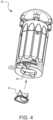
FIG. 4 is a perspective view illustrating one embodiment of a prosthetic heart valve ready to be inserted into the prosthetic suturing device ofFIG. 3 . -
FIG. 5 is a perspective view illustrating the prosthetic heart valve ofFIG. 4 inserted into the prosthetic suturing device ofFIG. 3 . -
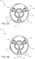
FIGS. 6A and 6B are top exposed views of the prosthetic suturing device illustrating one embodiment of a prosthetic retainer in a disengaged state and an engaged state, respectively, for retaining a prosthetic heart valve. -
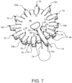
FIG. 7 illustrates two ferruled ends of a suture being loaded into a set of ferrule receivers in the ferrule platen ofFIG. 3 . -
FIG. 8 illustrates a fully loaded ferrule platen loaded into the prosthetic suturing device. -
FIG. 9 illustrates a platen locking ring engaged to hold the ferrule platen in place within the prosthetic suturing device. -
FIG. 10 is a perspective cross-sectional view of the prosthetic suturing device. - It will be appreciated that for purposes of clarity and where deemed appropriate, reference numerals have been repeated in the figures to indicate corresponding features, and that the various elements in the drawings have not necessarily been drawn to scale in order to better show the features.
-
FIG. 1 is a top perspective view of one embodiment of aprosthetic suturing device 30. Theprosthetic suturing device 30 has ahousing 32 which includes amain housing 34 and atop housing 36. Depending on the embodiment, thehousing 30 may also include one ormore grip features 38 to facilitate holding thedevice 30. Theprosthetic suturing device 30 also has anactuator 40, the features of which will be discussed later in this specification. -
FIG. 2 is a bottom perspective view of theprosthetic suturing device 30. Thehousing 32 defines aplaten opening 42 and aprosthetic opening 44. -
FIG. 3 is a perspective view illustrating one embodiment of aferrule platen 46 being removed from theprosthetic suturing device 30 via theplaten opening 42. Theferrule platen 46 is coupled to aplaten stem 48 which may advantageously be used to hold and manipulate theferrule platen 46. The platen opening 42 and theprosthetic opening 44 are joined together by astem notch 50 which is also defined by thehousing 32. Thestem notch 50 enables theplaten stem 48 to clear thehousing 32 while theplaten stem 48 is being used to remove theferrule platen 46 from theplaten opening 42. - As illustrated in
FIG. 4 , when theferrule platen 46 is removed from theprosthetic suturing device 30, a prosthetic device such as, but not limited toprosthetic heart valve 52 may be ready to be inserted into theprosthetic suturing device 30 via theprosthetic opening 44.FIG. 5 illustrates theprosthetic heart valve 52 inserted into theprosthetic suturing device 30. Thedevice 30 has a prosthetic retainer which can be engaged to hold theprosthetic valve 52 in place. InFIG. 5 , aprosthetic retainer tab 54 is visible protruding from thehousing 32. -
FIGS. 6A and 6B are top exposed views of the prosthetic suturing device illustrating one embodiment of aprosthetic retainer 56 in a disengaged state and an engaged state, respectively, for retaining theprosthetic heart valve 52. This embodiment of theprosthetic retainer 56 has a plurality of stud springs 58 which are slideably engaged with astud spring ring 60. In this embodiment, thestud spring ring 60 is made from two substantiallysemicircular pieces stud spring ring 60. The inner surface of thestud spring ring 60 varies in how far it protrudes towards the stud springs 58. In the disengaged position ofFIG. 6A , thestud spring ring 60 does not interfere with the stud springs 58 enough to push them into contact with theprosthetic valve 52. In the engaged position ofFIG. 6B , however, theprosthetic retainer tab 54 has been rotated clockwise (from the point of view ofFIG. 6B ), thereby rotating thestud spring ring 60 such that sections of the interior of thestud spring ring 60, which interfere more with the stud springs 58, push the stud springs 58 into contact with asewing cuff 64 of theprosthetic valve 52. Although not shown in this view, thedevice 30 has a prosthetic receiver which helps theprosthesis 52 to be positioned properly within thedevice 30. Theprosthetic retainer 56 illustrated inFIGS. 6A and 6B is used to hold theprosthesis 52 within the device's prosthetic receiver for suturing as will be described further in this specification. - In a surgical context, a prosthesis such as the
prosthetic valve 52 would be loaded into and retained within theprosthetic suturing device 30 as has been described above. Theferrule platen 46 which was removed from thedevice 30 prior to the loading of theprosthesis 52 is available to be loaded with sutures. As a non-limiting example, this specification will consider a cardiac surgical procedure to replace an aortic valve. The surgeon gains access to the aortic root via an aortotomy made in the ascending aorta. The leaflets of the diseased valve are dissected and removed. A series of sutures are then placed around the aortic annulus using a mattress suture stitch for each suture. The number of sutures placed around the annulus will vary based on a number of factors, including, but not limited to the size of the patient's annulus and/or surgeon preference. For the sake of discussion, this specification considers an example where twelve sutures are placed around the annulus. In a minimally invasive cardiac surgical procedure, the sutures may be placed through a very small incision between the patient's ribs using an automated suturing device such as the RAM® Device, available from LSI Solutions, Inc. of Victor, NY (www.lsisolutions.com). The ends of each suture will have small metal cylinders on them called ferrules. With twelve separate sutures being placed, the 24 ends of those sutures need to be managed and kept organized to avoid suture tangling and to ensure that corresponding suture ends may be identified. To further complicate the situation, different surgeons may proceed in a different order depending on how they prefer to approach the surgery. The aortic valve has three commissure points which are located at one hundred twenty degree positions around the aortic annulus. Some surgeons prefer to place separate sutures at the commissure points first and then fill in sutures in the spaces between. Other surgeons prefer to start at one of the commissures and work their way counterclockwise or clockwise around the annulus in consecutive order. - The
ferrule platen 46, shown inFIG. 7 , is designed to accommodate whichever way a surgeon prefers to work. Theferrule platen 46 has twenty-fourferrule holders 66 arranged in a circular pattern. In other embodiments, there could be a greater number or a lesser number of ferrule holders. Also, other embodiments might have theferrule holders 66 arrayed in a different shape. The circular shape in the embodiment ofFIG. 7 is compatible with the shape and dimensions of the sewing cuff for theprosthetic heart valve 52 which is being held in theprosthetic suturing device 30.Slots 68 extend from the periphery of theferrule platen 46 to eachferrule holder 66. Theslots 68 are wide enough to allow suture to be passed therethrough but not wide enough to allow a ferrule to pass. An indexing tab (either 70, 70N, or 70C) extends on the periphery of theferrule platen 46, each indexing tab between a corresponding pair offerrule holders 72. In this embodiment, there are threecommissure indexing tabs 70C, one for each of the Left-Non Commissure (LN com), the Right-Non Commissure (RN com), and the Left-Right Commissure (LR com). Since we are working with an embodiment meant to be used with an aortic annulus which needs twelve sutures, there are twelve indexing tabs in this example. Thecommissure indexing tabs 70C are located one hundred twenty degrees apart. With twelve total sutures, three of those sutures will be for the commissures. This leaves nine sutures, and three of those nine sutures will be located in each of the three spaces between the commissures. The mid-point between the commissures may be referred to as the nadir, and theferrule platen 46 has threenadir indexing tabs 70N. For the convenience of the surgical staff and for reference, thecommissure indexing tabs 70C are labelled in this embodiment ("LN com", "RN com", and "LR com") and they also have a distinct shape which protrudes farther than the other indexing tabs. Thenadir indexing tabs 70N are also labelled "ndr" in this embodiment. - The ends of a
suture 74 are being loaded into theferrule platen 46 inFIG. 7 . Specifically, the ends of thesuture 74 are being loaded into theferrule holders 66 which correspond to the Left-Non Commissure as denoted by thecommissure indexing tab 70C which is labelled "LN com". In this embodiment, theferrule platen 46 has two lower layers: aferrule stop plate 76 and a suture retaining plate 78. Theferrule stop plate 76 has holes and slots which correspond to theferrule platen 46, but the holes are sized to prevent a ferrule placed into theferrule platen 46 from passing through theferrule stop plate 76. The suture retaining plate 78 may be configured to have even tighter holes and slots in order to grasp a suture placed therein in order to help keep the ferrules placed into theferrule platen 46 from falling out. Some embodiments may not have a suture retaining plate. Other embodiments may incorporate the features of theferrule stop plate 76 and/or the suture retaining plate 78 into theferrule platen 46. - The ends of
suture 74 inFIG. 7 haveferrules 80 on them. As shown inFIG. 7 , theferrules 80 still need to be pulled down into theferrule holders 66. When fully installed, theferrules 80 will be held within theferrule holders 66. As the cardiac surgical procedure continues, all of the twenty-four suture ends for the twelve annular sutures can be placed within appropriate slots/ferrule holders of theferrule platen 46 in order to keep them organized. - As shown in
FIG. 8 , a fully loadedferrule platen 46 can be placed back into theplaten opening 42 of theprosthetic suturing device 30. Thesutures 74 can pass through thestem notch 50 so that they hang through theprosthetic opening 44. As illustrated inFIG. 9 , aplaten locking tab 82 on aplaten locking ring 84 may be used to rotate theplaten locking ring 84 into a position which holds the ferrule platen in a desired location within theprosthetic suture device 30. -
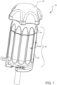
FIG. 10 is a perspective cross-sectional view of theprosthetic suturing device 30 shown while loaded with a prostheticaortic valve 52. For simplicity, only twoferrules 80 are shown in theferrule platen 46. It should be understood, however, that each of the twenty four ferrules which may be loaded in theferrule platen 46 would be manipulated the same way as will be discussed for theexample ferrules 80. - In this embodiment, the
actuator 40 has acontrol knob 86 which is coupled to adrive screw 88. Thedrive screw 88 is in threaded engagement with aneedle press 90 which is slideable within themain housing 34. Thecontrol knob 86 is free to rotate with respect to thetop housing 36, but is constrained from moving axially with respect to thetop housing 36. Thus, rotation of thecontrol knob 86 in one direction will cause theneedle press 90 to move towards theferrule platen 46, while rotation of thecontrol knob 86 in the opposite direction will cause theneedle press 90 to move away from theferrule platen 46 as the threads of thedrive screw 88 engage the corresponding threads in theneedle press 90. A plurality of needles 92 (one for eachferrule holder 66 in the ferrule platen 46) are coupled to theneedle press 90. Each of theneedles 92 is held by theneedle press 90 in alignment with acorresponding ferrule holder 66 of theferrule platen 46. In this embodiment, one or more needle latches 94 hold theneedles 92 in place within theneedle press 90. - As shown in
FIG. 10 , theneedles 92 are in a retracted position. Thetip 96 of eachneedle 92 is housed within aneedle track 98. Theneedle track 98 is fixed with respect to themain housing 34 in this embodiment. Since theneedle tips 96 are within theneedle track 98 in this retracted position, the users are protected from being pierced or cut by the needles when loading theprosthetic valve 52 into the device. Theneedle track 98 may also define aprosthetic receiver 100 which can provide clearance for fragile structures of the prosthesis (such as prosthetic valve leaflets) and may also provide a surface for less fragile structures (such as a prosthetic sewing cuff) to rest against for support and orientation purposes before the prosthetic retainer is engaged to hold theprosthesis 52 in place. - Once the
prosthesis 52 has been retained in place and the loadedferrule platen 46 has been locked into place, as illustrated inFIG. 10 , thecontrol knob 86 may be rotated to cause theneedle press 90 to advance theneedle tips 96 out of theneedle track 98 towards and through thesewing cuff 64 of theprosthetic valve 52 and into contact with correspondingferrules 80. Theneedle tips 96 are sized to have an interference fit with the openings of theferrules 80, thereby coupling theferrules 80 to theneedle tips 96. Thecontrol knob 86 may then be rotated in the opposite direction to draw theneedles 92 back towards their starting position. Since theferrules 80 are coupled to theneedle tips 96, this will pull the ends of thesuture 74 through theprosthetic sewing cuff 64. After theneedles 92 have been retracted, theplaten locking ring 84 may be rotated back to the open position ofFIG. 8 by theplaten locking tab 82 so that theferrule platen 46 may be removed from thedevice 30. Similarly, theprosthetic retaining tab 54 may be rotated to release the prosthetic valve 52 (prosthetic retaining features discussed previously are not shown inFIG. 10 for simplicity). Theprosthesis 52 may be removed, and the user will find that all of the sutures have been passed through thesewing cuff 64 in a single action. In addition to the suture organization benefits, this device has the potential to greatly reduce the amount of time it takes to suture and install a prosthesis. Such time savings can be highly beneficial to the patient, especially in a cardiac surgical procedure where the patient is often on cardio-pulmonary bypass (CPB). Shorter time on CPB has been shown to reduce morbidity and mortality in surgical patients. - Although the actuator illustrated in the embodiments above utilizes a drive screw to advance the needles through the prosthetic sewing cuff, other embodiments may utilize other types of actuators, including, but not limited to lever actuators, gear-based actuators, motorized actuators, solenoid driven actuators, or any combination and/or plurality thereof.
- While the embodiments discussed above were configured to be used with a prosthetic cardiac valve, other embodiments may be configured to be used with other types of prosthetic devices, such as, but not limited to, an annuloplasty ring or a sewing cuff for a ventricular assist device such as the HeartMate III™ device.
- Various advantages of a prosthetic suturing device and methods thereof have been discussed above. Embodiments discussed herein have been described by way of example in this specification. It will be apparent to those skilled in the art that the forgoing detailed disclosure is intended to be presented by way of example only. Various alterations, improvements, and modifications will occur and are intended to those skilled in the art, though not expressly stated herein. These alterations, improvements, and modifications are intended to be suggested hereby.
Claims (15)
- A prosthetic suturing device (30), comprising:a housing (32);a needle press (90) slideably engaged with the housing (32);a plurality of needles (92) coupled to the needle press (90);a prosthetic retainer (56);a ferrule platen (46) having a plurality of ferrule holders (66), each corresponding to one of the plurality of needles (92); andan actuator (40) configured to move the needle press (90) from a retracted position where needle tips (96) of the plurality of needles (92) are away from the ferrule platen (46) to an engaged position where the needle tips (96) of the plurality of needles (92) are at least partially within the ferrule holders (66) of the ferrule platen (46).
- The prosthetic suturing device (30) of claim 1, wherein the plurality of needles (92) are coupled to the needle press (90) by one or more needle latches (94); and/or
wherein the plurality of needles (92) are arranged on the needle press (90) in a substantially circular pattern. - The prosthetic suturing device (30) of claim 1, wherein the prosthetic retainer (56) comprises:one or more stud springs (58);a stud spring ring (60) engageable with the one or more stud springs (58); anda prosthetic retainer tab (54) coupled to the stud spring ring (60).
- The prosthetic suturing device (30) of claim 1, wherein the ferrule platen (46) further comprises a ferrule stop plate (76) and/or a suture retaining plate (78);wherein the ferrule stop plate (76) has holes sized to prevent a ferrule placed into the ferrule platen (46) from passing through the ferrule stop plate (76); andwherein the suture retaining plate (78) has holes configured to grasp a suture placed therein in order to help keep the ferrules placed into the ferrule platen (46) from falling out.
- The prosthetic suturing device (30) of claim 1, wherein the ferrule platen (46) further comprises a plurality of indexing tabs (70, 70C, 70N);
wherein preferably the plurality of indexing tabs comprise one or more commissure indexing tabs (70C) and/or one or more nadir indexing tabs (70N). - The prosthetic suturing device (30) of claim 1, wherein the housing (32) defines a platen opening (42) and/or a prosthetic opening (44).
- The prosthetic suturing device (30) of claim 1, wherein the housing (32) defines:a platen opening (42);a prosthetic opening (44); anda stem notch (50) which joins the platen opening (42) and the prosthetic opening (44).
- The prosthetic suturing device (30) of claim 6 or 7, further comprising a platen stem (48) coupled to the ferrule platen (46) and configured to be used to remove the ferrule platen (46) from the platen opening (42).
- The prosthetic suturing device (30) of claim 1, further comprising a needle track (98) coupled to the housing (32).
- The prosthetic suturing device (30) of claim 8, wherein the needle track (98) comprises a plurality of holes, each corresponding to a different one of the plurality of needles (92); and/or
wherein the needle tips (96) are located within the needle track (98) while the device is in the retracted position. - The prosthetic suturing device (30) of claim 8, wherein the needle track (98) further defines a prosthetic receiver (100).
- The prosthetic suturing device (30) of claim 1, further comprising a prosthetic receiver (100).
- The prosthetic suturing device (30) of claim 1, wherein the actuator (40) comprises:a control knob (86); anda drive screw (88) coupled to the control knob (86);wherein preferably the drive screw (88) is in threaded engagement with the needle press (90).
- The prosthetic suturing device (30) of claim 1, wherein the actuator (40) comprises a device selected from the group consisting of a lever, a gear, an motor, and a solenoid.
- The prosthetic suturing device (30) of claim 1, wherein the prosthetic retainer (56) is configured to hold a prosthetic device selected from the group consisting of a prosthetic aortic valve, a prosthetic mitral valve, a prosthetic heart valve, a sewing cuff for a ventricular assist device, and an annuloplasty ring.
Applications Claiming Priority (3)
| Application Number | Priority Date | Filing Date | Title |
|---|---|---|---|
| US201862622868P | 2018-01-27 | 2018-01-27 | |
| EP19744494.6A EP3661429B1 (en) | 2018-01-27 | 2019-01-28 | Prosthetic suturing device |
| PCT/US2019/015454 WO2019148121A1 (en) | 2018-01-27 | 2019-01-28 | Prosthetic suturing device and methods thereof |
Related Parent Applications (1)
| Application Number | Title | Priority Date | Filing Date |
|---|---|---|---|
| EP19744494.6A Division EP3661429B1 (en) | 2018-01-27 | 2019-01-28 | Prosthetic suturing device |
Publications (2)
| Publication Number | Publication Date |
|---|---|
| EP4238507A2 true EP4238507A2 (en) | 2023-09-06 |
| EP4238507A3 EP4238507A3 (en) | 2023-11-29 |
Family
ID=67391177
Family Applications (2)
| Application Number | Title | Priority Date | Filing Date |
|---|---|---|---|
| EP19744494.6A Active EP3661429B1 (en) | 2018-01-27 | 2019-01-28 | Prosthetic suturing device |
| EP23185842.4A Pending EP4238507A3 (en) | 2018-01-27 | 2019-01-28 | Prosthetic suturing device |
Family Applications Before (1)
| Application Number | Title | Priority Date | Filing Date |
|---|---|---|---|
| EP19744494.6A Active EP3661429B1 (en) | 2018-01-27 | 2019-01-28 | Prosthetic suturing device |
Country Status (3)
| Country | Link |
|---|---|
| US (2) | US20200397426A1 (en) |
| EP (2) | EP3661429B1 (en) |
| WO (1) | WO2019148121A1 (en) |
Families Citing this family (8)
| Publication number | Priority date | Publication date | Assignee | Title |
|---|---|---|---|---|
| US9308087B2 (en) | 2011-04-28 | 2016-04-12 | Neovasc Tiara Inc. | Sequentially deployed transcatheter mitral valve prosthesis |
| US10856984B2 (en) | 2017-08-25 | 2020-12-08 | Neovasc Tiara Inc. | Sequentially deployed transcatheter mitral valve prosthesis |
| AU2019374743B2 (en) | 2018-11-08 | 2022-03-03 | Neovasc Tiara Inc. | Ventricular deployment of a transcatheter mitral valve prosthesis |
| EP3934591A4 (en) | 2019-03-08 | 2022-11-23 | Neovasc Tiara Inc. | Retrievable prosthesis delivery system |
| CA3136334A1 (en) | 2019-04-10 | 2020-10-15 | Neovasc Tiara Inc. | Prosthetic valve with natural blood flow |
| CN114025813B (en) | 2019-05-20 | 2024-05-14 | 内奥瓦斯克迪亚拉公司 | Introducer with hemostatic mechanism |
| CN114144144A (en) | 2019-06-20 | 2022-03-04 | 内奥瓦斯克迪亚拉公司 | Low-profile prosthetic mitral valve |
| US20220395269A1 (en) * | 2021-06-09 | 2022-12-15 | The Regents Of The University Of Colorado | Arthroscopic Suture Management Device |
Citations (3)
| Publication number | Priority date | Publication date | Assignee | Title |
|---|---|---|---|---|
| WO2000059382A1 (en) | 1999-04-01 | 2000-10-12 | Bjerken David B | Vacuum-assisted remote suture placement system |
| US20070213757A1 (en) | 2006-02-09 | 2007-09-13 | Sreevathsa Boraiah | Laparoscopic trocar and facial closure systems and methods |
| US20150282805A1 (en) | 2014-04-08 | 2015-10-08 | Lsi Solutions, Inc. | Surgical suturing device for a replacement anatomical structure and methods thereof |
Family Cites Families (12)
| Publication number | Priority date | Publication date | Assignee | Title |
|---|---|---|---|---|
| US4185636A (en) * | 1977-12-29 | 1980-01-29 | Albert Einstein College Of Medicine Of Yeshiva University | Suture organizer, prosthetic device holder, and related surgical procedures |
| US20020095164A1 (en) * | 1997-06-26 | 2002-07-18 | Andreas Bernard H. | Device and method for suturing tissue |
| US5728151A (en) * | 1993-02-22 | 1998-03-17 | Heartport, Inc. | Intercostal access devices for less-invasive cardiovascular surgery |
| US5871489A (en) * | 1996-01-24 | 1999-02-16 | S.M.T. (Medical Technologies) Ltd | Surgical implement particularly useful for implanting prosthetic heart valves, valve holder particularly useful therewith and surgical method including such implement |
| US6730102B1 (en) * | 2000-11-06 | 2004-05-04 | Abbott Laboratories | Systems, devices and methods for deploying needles |
| EP1337188B1 (en) * | 2000-11-16 | 2012-03-07 | Donald J. Hill | Automatic suture fixation apparatus and method |
| US6749615B2 (en) * | 2001-06-25 | 2004-06-15 | Abbott Laboratories | Apparatus and methods for performing an anastomosis |
| WO2004098418A1 (en) * | 2003-04-16 | 2004-11-18 | Tyco Healthcare Group Lp | Method and apparatus for radical prostatectomy anastomosis including an anchor for engaging a body vessel and deployable sutures |
| US7871432B2 (en) * | 2006-08-02 | 2011-01-18 | Medtronic, Inc. | Heart valve holder for use in valve implantation procedures |
| US20090005794A1 (en) * | 2007-06-28 | 2009-01-01 | Biomet Sports Medicine, Inc. | Suture Holding Device |
| US10492779B2 (en) * | 2017-02-20 | 2019-12-03 | Edwards Lifesciences Corporation | Suturing devices for heart valve surgery |
| FR3072013B1 (en) * | 2017-10-09 | 2019-09-27 | Cmi'nov | DEVICE FOR SUTURING A CARDIAC VALVULAR PROSTHESIS |
-
2019
- 2019-01-28 US US16/644,085 patent/US20200397426A1/en not_active Abandoned
- 2019-01-28 US US16/259,854 patent/US11039828B2/en active Active
- 2019-01-28 EP EP19744494.6A patent/EP3661429B1/en active Active
- 2019-01-28 EP EP23185842.4A patent/EP4238507A3/en active Pending
- 2019-01-28 WO PCT/US2019/015454 patent/WO2019148121A1/en unknown
Patent Citations (3)
| Publication number | Priority date | Publication date | Assignee | Title |
|---|---|---|---|---|
| WO2000059382A1 (en) | 1999-04-01 | 2000-10-12 | Bjerken David B | Vacuum-assisted remote suture placement system |
| US20070213757A1 (en) | 2006-02-09 | 2007-09-13 | Sreevathsa Boraiah | Laparoscopic trocar and facial closure systems and methods |
| US20150282805A1 (en) | 2014-04-08 | 2015-10-08 | Lsi Solutions, Inc. | Surgical suturing device for a replacement anatomical structure and methods thereof |
Also Published As
| Publication number | Publication date |
|---|---|
| EP3661429A1 (en) | 2020-06-10 |
| WO2019148121A1 (en) | 2019-08-01 |
| EP3661429A4 (en) | 2021-06-09 |
| US11039828B2 (en) | 2021-06-22 |
| US20200397426A1 (en) | 2020-12-24 |
| EP4238507A3 (en) | 2023-11-29 |
| EP3661429B1 (en) | 2023-07-19 |
| US20190231344A1 (en) | 2019-08-01 |
Similar Documents
| Publication | Publication Date | Title |
|---|---|---|
| EP3661429B1 (en) | Prosthetic suturing device | |
| US11707271B2 (en) | Suturing devices for heart valve surgery | |
| US12070205B2 (en) | Surgical suturing device for a replacement anatomical structure and methods thereof | |
| US7871432B2 (en) | Heart valve holder for use in valve implantation procedures | |
| JP6345775B2 (en) | Knotless suture fastener installation system | |
| US20200268374A1 (en) | Device for suturing a heart valve prosthesis | |
| US20080071367A1 (en) | Heart valve holder for use in valve implantation procedures | |
| EP1723935B1 (en) | Prosthetic heart valve system | |
| US20110082539A1 (en) | Minimally invasive aortic valve replacement | |
| US11918464B2 (en) | Prosthetic suturing device and methods thereof | |
| US11266398B2 (en) | Automated suturing adapter, assembly, and methods thereof | |
| EP3558141A1 (en) | Prosthetic suturing device and methods thereof | |
| EP3714820B1 (en) | A cannula to be particularly used in conjunction with suture placement systems for use in minimally invasive surgeries | |
| CN117982264A (en) | Valve holder for artificial heart valve | |
| WO2023239751A1 (en) | System and method for cardiac valve repair | |
| CN117982263A (en) | Valve holder for artificial heart valve |
Legal Events
| Date | Code | Title | Description |
|---|---|---|---|
| PUAI | Public reference made under article 153(3) epc to a published international application that has entered the european phase |
Free format text: ORIGINAL CODE: 0009012 |
|
| STAA | Information on the status of an ep patent application or granted ep patent |
Free format text: STATUS: THE APPLICATION HAS BEEN PUBLISHED |
|
| AC | Divisional application: reference to earlier application |
Ref document number: 3661429 Country of ref document: EP Kind code of ref document: P |
|
| AK | Designated contracting states |
Kind code of ref document: A2 Designated state(s): AL AT BE BG CH CY CZ DE DK EE ES FI FR GB GR HR HU IE IS IT LI LT LU LV MC MK MT NL NO PL PT RO RS SE SI SK SM TR |
|
| REG | Reference to a national code |
Ref country code: DE Ref legal event code: R079 Free format text: PREVIOUS MAIN CLASS: A61B0017060000 Ipc: A61B0017040000 |
|
| PUAL | Search report despatched |
Free format text: ORIGINAL CODE: 0009013 |
|
| AK | Designated contracting states |
Kind code of ref document: A3 Designated state(s): AL AT BE BG CH CY CZ DE DK EE ES FI FR GB GR HR HU IE IS IT LI LT LU LV MC MK MT NL NO PL PT RO RS SE SI SK SM TR |
|
| RIC1 | Information provided on ipc code assigned before grant |
Ipc: A61B 17/06 20060101ALI20231023BHEP Ipc: A61F 2/24 20060101ALI20231023BHEP Ipc: A61B 17/04 20060101AFI20231023BHEP |
|
| STAA | Information on the status of an ep patent application or granted ep patent |
Free format text: STATUS: REQUEST FOR EXAMINATION WAS MADE |
|
| 17P | Request for examination filed |
Effective date: 20240528 |
|
| RBV | Designated contracting states (corrected) |
Designated state(s): AL AT BE BG CH CY CZ DE DK EE ES FI FR GB GR HR HU IE IS IT LI LT LU LV MC MK MT NL NO PL PT RO RS SE SI SK SM TR |