EP4238461A1 - Hand-held mixer - Google Patents
Hand-held mixer Download PDFInfo
- Publication number
- EP4238461A1 EP4238461A1 EP23159517.4A EP23159517A EP4238461A1 EP 4238461 A1 EP4238461 A1 EP 4238461A1 EP 23159517 A EP23159517 A EP 23159517A EP 4238461 A1 EP4238461 A1 EP 4238461A1
- Authority
- EP
- European Patent Office
- Prior art keywords
- beater
- hand
- pillar
- battery pack
- motor
- Prior art date
- Legal status (The legal status is an assumption and is not a legal conclusion. Google has not performed a legal analysis and makes no representation as to the accuracy of the status listed.)
- Pending
Links
- 238000000034 method Methods 0.000 description 11
- 230000008569 process Effects 0.000 description 8
- 230000000994 depressogenic effect Effects 0.000 description 5
- 239000000463 material Substances 0.000 description 4
- 230000009471 action Effects 0.000 description 3
- 238000012986 modification Methods 0.000 description 3
- 230000004048 modification Effects 0.000 description 3
- 239000003086 colorant Substances 0.000 description 2
- 238000010276 construction Methods 0.000 description 2
- 230000000712 assembly Effects 0.000 description 1
- 238000000429 assembly Methods 0.000 description 1
- 230000008878 coupling Effects 0.000 description 1
- 238000010168 coupling process Methods 0.000 description 1
- 238000005859 coupling reaction Methods 0.000 description 1
- 230000000694 effects Effects 0.000 description 1
- 238000006467 substitution reaction Methods 0.000 description 1
Images


Classifications
-
- A—HUMAN NECESSITIES
- A47—FURNITURE; DOMESTIC ARTICLES OR APPLIANCES; COFFEE MILLS; SPICE MILLS; SUCTION CLEANERS IN GENERAL
- A47J—KITCHEN EQUIPMENT; COFFEE MILLS; SPICE MILLS; APPARATUS FOR MAKING BEVERAGES
- A47J43/00—Implements for preparing or holding food, not provided for in other groups of this subclass
- A47J43/04—Machines for domestic use not covered elsewhere, e.g. for grinding, mixing, stirring, kneading, emulsifying, whipping or beating foodstuffs, e.g. power-driven
- A47J43/07—Parts or details, e.g. mixing tools, whipping tools
- A47J43/08—Driving mechanisms
- A47J43/082—Driving mechanisms for machines with tools driven from the upper side
-
- A—HUMAN NECESSITIES
- A47—FURNITURE; DOMESTIC ARTICLES OR APPLIANCES; COFFEE MILLS; SPICE MILLS; SUCTION CLEANERS IN GENERAL
- A47J—KITCHEN EQUIPMENT; COFFEE MILLS; SPICE MILLS; APPARATUS FOR MAKING BEVERAGES
- A47J43/00—Implements for preparing or holding food, not provided for in other groups of this subclass
- A47J43/04—Machines for domestic use not covered elsewhere, e.g. for grinding, mixing, stirring, kneading, emulsifying, whipping or beating foodstuffs, e.g. power-driven
- A47J43/044—Machines for domestic use not covered elsewhere, e.g. for grinding, mixing, stirring, kneading, emulsifying, whipping or beating foodstuffs, e.g. power-driven with tools driven from the top side
-
- A—HUMAN NECESSITIES
- A47—FURNITURE; DOMESTIC ARTICLES OR APPLIANCES; COFFEE MILLS; SPICE MILLS; SUCTION CLEANERS IN GENERAL
- A47J—KITCHEN EQUIPMENT; COFFEE MILLS; SPICE MILLS; APPARATUS FOR MAKING BEVERAGES
- A47J43/00—Implements for preparing or holding food, not provided for in other groups of this subclass
- A47J43/04—Machines for domestic use not covered elsewhere, e.g. for grinding, mixing, stirring, kneading, emulsifying, whipping or beating foodstuffs, e.g. power-driven
- A47J43/07—Parts or details, e.g. mixing tools, whipping tools
- A47J43/0705—Parts or details, e.g. mixing tools, whipping tools for machines with tools driven from the upper side
-
- A—HUMAN NECESSITIES
- A47—FURNITURE; DOMESTIC ARTICLES OR APPLIANCES; COFFEE MILLS; SPICE MILLS; SUCTION CLEANERS IN GENERAL
- A47J—KITCHEN EQUIPMENT; COFFEE MILLS; SPICE MILLS; APPARATUS FOR MAKING BEVERAGES
- A47J43/00—Implements for preparing or holding food, not provided for in other groups of this subclass
- A47J43/04—Machines for domestic use not covered elsewhere, e.g. for grinding, mixing, stirring, kneading, emulsifying, whipping or beating foodstuffs, e.g. power-driven
- A47J43/044—Machines for domestic use not covered elsewhere, e.g. for grinding, mixing, stirring, kneading, emulsifying, whipping or beating foodstuffs, e.g. power-driven with tools driven from the top side
- A47J2043/04409—Apparatus of hand held type
- A47J2043/04418—Apparatus of hand held type with housing extending perpendicular, e.g. horizontally, from the tool axis
Definitions
- the present disclosure generally relates to a hand-held mixer, and more specifically to a battery-powered hand-held mixer.
- a hand-held mixer includes a housing having a front side and a rear side opposite the front side.
- a pillar is coupled to the housing at a pillar proximal end and extends outward therefrom to a pillar distal end.
- a motor is positioned within at least one of the housing and the pillar.
- a first beater hub removably receives a first beater having a beater head and a shaft coupled to the beater head. The first beater hub is operably engaged with the motor such that, in an engaged condition of the first beater, operation of the motor drives rotation of the first beater about a first beater axis of rotation.
- a battery receptacle is disposed at the pillar distal end and configured to receive a battery pack that has a battery for powering the motor such that the battery pack is operable between a docked condition and an undocked condition.
- the battery pack In the docked condition, the battery pack is engaged with the battery receptacle to provide power to the motor.
- the battery pack In an undocked condition, the battery pack is disengaged from the battery receptacle.
- the battery pack moves along a battery pack axis that is substantially perpendicular to the first beater axis of rotation from the undocked condition to the docked condition.
- the terms “upper,” “lower,” “right,” “left,” “rear,” “front,” “vertical,” “horizontal,” and derivatives thereof shall relate to the disclosure as oriented in FIG. 10 .
- the term “front” shall refer to the surface of the element closer to an intended viewer, and the term “rear” shall refer to the surface of the element further from the intended viewer.
- the disclosure may assume various alternative orientations, except where expressly specified to the contrary.
- the specific devices and processes illustrated in the attached drawings, and described in the following specification are psimply exemplary embodiments of the inventive concepts defined in the appended claims. Hence, specific dimensions and other physical characteristics relating to the embodiments disclosed herein are not to be considered as limiting, unless the claims expressly state otherwise.
- the term "and/or,” when used in a list of two or more items, means that any one of the listed items can be employed by itself, or any combination of two or more of the listed items can be employed.
- the composition can contain A alone; B alone; C alone; A and B in combination; A and C in combination; B and C in combination; or A, B, and C in combination.
- substantially is intended to note that a described feature is equal or approximately equal to a value or description.
- a “substantially planar” surface is intended to denote a surface that is planar or approximately planar.
- substantially is intended to denote that two values are equal or approximately equal.
- substantially may denote values within about 10% of each other, such as within about 5% of each other, or within about 2% of each other.
- the terms “the,” “a,” or “an,” mean “at least one,” and should not be limited to “only one” unless explicitly indicated to the contrary.
- reference to “a component” includes embodiments having two or more such components unless the context clearly indicates otherwise.
- reference numeral 10 generally designates a hand-held mixer.
- the hand-held mixer 10 includes a housing 12.
- the housing 12 includes a front side 14 and a rear side 16 that is opposite the front side 14.
- the front side 14 of the housing 12 defines a first aperture 18 and a second aperture 20.
- the first and second apertures 18, 20 are configured to receive shafts 22 of first and second beaters 24, 26 therein, respectively.
- the hand-held mixer 10 further includes a motor 28. As illustrated in FIGS. 4 and 6 , the motor 28 is positioned within the housing 12 of the hand-held mixer 10. In various implementations, the motor 28 is configured to drive rotation of a drive shaft 30 of the motor 28 about a drive shaft axis of rotation 32, as illustrated in FIGS. 6 and 9 .
- the drive shaft axis of rotation 32 may extend through the front and rear sides 14, 16 of the housing 12.
- a variety of types of motors 28 configured to drive rotation of the drive shaft 30 about the drive shaft axis of rotation 32 are contemplated.
- the hand-held mixer 10 includes a gearbox 34.
- the gearbox 34 is disposed within the housing 12 of the hand-held mixer 10.
- the gearbox 34 is positioned between the front side 14 of the housing 12 and the motor 28 of the hand-held mixer 10.
- the gearbox 34 includes a plurality of gears 36.
- a variety of types of gears 36 are contemplated.
- the gearbox 34 includes a plurality of helical gears 36.
- the plurality of gears 36 of the gearbox 34 are configured to interlock and are rotated by the drive shaft 30 which is rotated by the motor 28.
- the plurality of gears 36 are configured to convert rotational movement of the drive shaft 30 to rotational movement of the first and second beaters 24, 26.
- the hand-held mixer 10 can include a first beater hub 35 and a second beater hub 37.
- the first beater hub 35 and the second beater hub 37 are operably engaged with the motor 28.
- the first and second beater hubs 35, 37 can be operably engaged with the motor 28 via the gearbox 34.
- the first beater hub 35 and the second beater hub 37 can receive portions of first and second beaters 24, 26, respectively, therein during operation of the hand-held mixer 10.
- the first and second beater hubs 35, 37 can removably receive portions of the first and second beaters 24, 26 therein, such as within apertures of the first and second beater hubs 35, 37, as described further herein.
- the hand-held mixer 10 includes a first beater 24 and a second beater 26.
- the first and second beaters 24, 26 each include a beater head 38 and a shaft 22 that is coupled to the beater head 38.
- the first beater 24 is operable between an engaged condition and a disengaged condition. In the engaged condition, the shaft 22 of the first beater 24 is partially inserted into the first aperture 18 that is defined by the front side 14 of the housing 12, as illustrated in FIGS. 2 and 4 .
- the shaft 22 of the first beater 24 is operably engaged with the motor 28 via the gearbox 34, such that rotation of the drive shaft 30 about the drive shaft axis of rotation 32 causes the first beater 24 to rotate about a first beater axis of rotation 40.
- the first beater axis of rotation 40 is substantially parallel to the drive shaft axis of rotation 32.
- the shaft 22 of the first beater 24 is removable from the first aperture 18 defined by the housing 12 in the disengaged condition, as illustrated in FIG. 3 .
- the second beater 26 of the hand-held mixer 10 is operable between an engaged condition and a disengaged condition.
- the shaft 22 of the second beater 26 is partially inserted into the second aperture 20 that is defined by the front side 14 of the housing 12, as illustrated in FIGS. 2 and 4 .
- the second beater 26 is operably engaged with the motor 28 of the hand-held mixer 10 via the gearbox 34 while the second beater 26 is in the engaged condition, such that rotation of the drive shaft 30 about the drive shaft axis of rotation 32 causes the second beater 26 to rotate about a second beater axis of rotation 42.
- the second beater axis of rotation 42 is substantially parallel to the drive shaft axis of rotation 32 and the first beater axis of rotation 40.
- the shaft 22 of the second beater 26 is not operably engaged with the motor 28 via the gearbox 34, and the shaft 22 is removable from the second aperture 20 defined by the housing 12.
- the hand-held mixer 10 can include more or fewer beaters, in some implementations.
- the hand-held mixer 10 can include four beaters in some embodiments.
- the hand-held mixer 10 can include an ejector button 44.
- the ejector button 44 can be positioned at the rear side 16 of the housing 12.
- the ejector button 44 is configured to be depressed to prompt the first and second beaters 24, 26 to enter the disengaged conditions, as illustrated in FIG. 3 , from the engaged conditions, as illustrated in FIG. 2 , respectively.
- the ejector button 44 is configured to be depressed in a direction that is parallel to at least one of the first beater axis of rotation 40, the second beater axis of rotation 42, and the drive shaft axis of rotation 32. In the embodiment illustrated in FIGS.
- the ejector button 44 is configured to be depressed toward the front side 14 of the housing 12 to release the first and second beaters 24, 26 from their operable engagement with the motor 28.
- a spring 46 is coupled to the ejector button 44, such that the ejector button 44 is spring-loaded. It is contemplated that the ejector button 44 may be continually biased toward the undepressed position, as illustrated in FIG. 1 , by the spring 46.
- the hand-held mixer 10 can include a control feature 48 for controlling operation of the motor 28.
- the control feature 48 is a rotary control ring 50.
- the rotary control ring 50 is disposed at the rear side 16 of the housing 12 and encircles the ejector button 44 of the hand-held mixer 10.
- the rotary control ring 50 includes a tab 52 that extends outward from the rotary control ring 50 away from the front side 14 of the housing 12.
- the tab 52 may provide a handhold for a user adjusting the rotary control ring 50, and may indicate which setting the motor 28 is configured to be operated on based on the position of the tab 52.
- the rotary control ring 50 is operable to move rotationally about the ejector button 44 to control operation of the motor 28.
- the rotary control ring 50 may be rotated clockwise from the perspective of FIG. 5 about the ejector button 44 to turn on the motor 28 and/or intensify operation of the motor 28.
- a variety of types of control features are contemplated.
- the rotary control ring 50 may partially encircle the ejector button 44, in some implementations.
- the rotary control ring 50 may extend around a majority of a circumference of the ejector button 44, in some implementations.
- the control feature 48 if the control feature 48 is switched to an "on" setting while the motor 28 is disconnected from a power source (e.g., a battery 74 is not connected to the hand-held mixer 10), subsequent connection of the motor 28 to the power source does not cause the motor 28 to turn on. Instead, once the power source is connected, switching the control feature 48 to an "off” setting and then switching the control feature 48 back to the "on” setting causes the motor 28 to turn on. As such, unexpected operation of the motor 28 when a power source is connected to the hand-held mixer 10 may be avoided.
- a power source e.g., a battery 74 is not connected to the hand-held mixer 10
- the hand-held mixer 10 includes a first pillar 54.
- the first pillar 54 is coupled to the housing 12 at a first pillar proximal end 56.
- the first pillar 54 extends outward from the first pillar proximal end 56 to a first pillar distal end 58 that is distal from the housing 12.
- the hand-held mixer 10 further includes a second pillar 60 that is coupled to the housing 12.
- the second pillar 60 is coupled to the housing 12 at a second pillar proximal end 62 and extends outward from the housing 12 to a second pillar distal end 64.
- the second pillar 60 is nearer than the first pillar 54 to the front side 14 of the housing 12. Further, as illustrated in FIGS. 2 and 3 , the second pillar 60 may be larger than the first pillar 54.
- the hand-held mixer 10 includes a battery receptacle 66.
- the battery receptacle 66 is coupled to the first and second pillar distal ends 58, 64 of the first and second pillars 54, 60. As illustrated in FIGS. 2 and 3 , the battery receptacle 66 extends between the first pillar distal end 58 and the second pillar distal end 64.
- the battery receptacle 66, the first pillar 54, the housing 12, and the second pillar 60 form a loop 68 that defines a handle aperture 70.
- a portion of a hand of a user may extend through the handle aperture 70 defined by the hand-held mixer 10, as the user grabs the first pillar 54 to operate the hand-held mixer 10.
- the battery receptacle 66 may be configured to receive a battery pack 72 for powering the motor 28 of the hand-held mixer 10.
- wires and other electrical components may extend from the battery receptacle 66 to the motor 28 within the housing 12 through the interior of the first and/or second pillars 54, 60 of the hand-held mixer 10.
- the battery receptacle 66 may be configured to receive the battery pack 72 of the hand-held mixer 10. It is contemplated that at least a portion of the housing 12, the first and/or second pillars 54, 60, and/or the battery receptacle 66 may be integrally coupled to each other.
- the hand-held mixer 10 can include an outer shell that forms at least a portion of the housing 12, the first and second pillars 54, 60, and the battery receptacle 66.
- the hand-held mixer 10 includes the battery pack 72.
- the battery pack 72 includes a battery 74 that is configured to power the motor 28 of the hand-held mixer 10.
- the battery pack 72 is operable between a docked condition, as illustrated in FIG. 2 , and an undocked condition, as illustrated in FIG. 3 .
- the battery pack 72 In the docked condition of the battery pack 72, the battery pack 72 is engaged with the battery receptacle 66 to provide power to the motor 28 of the hand-held mixer 10.
- the battery pack 72 is disengaged from the battery receptacle 66, as illustrated in FIG. 3 .
- the battery pack 72 is operable to move from the undocked condition to the docked condition along a battery pack axis 76.
- the battery pack axis 76 may be substantially parallel to the drive shaft axis of rotation 32, the first beater axis of rotation 40, and/or the second beater axis of rotation 42.
- the battery pack 72 may move between the docked and undocked conditions in a direction that is substantially parallel to the drive shaft axis of rotation 32, the first beater axis of rotation 40, and/or the second beater axis of rotation 42, in some implementations.
- the battery pack 72 moves from the undocked condition to the docked condition along the battery pack axis 76, which is substantially parallel to the drive shaft axis of rotation 32, first beater axis of rotation 40, and second beater axis of rotation 42, such that the battery pack 72 is nearer to the front side 14 of the housing 12 in the docked condition than in the undocked condition.
- the battery 74 moves toward the front of the hand-held mixer 10 as the battery 74 moves along the battery pack axis 76 from the undocked condition to the docked condition.
- the battery receptacle 66 may guide the direction of movement of the battery pack 72 along the battery pack axis 76.
- a battery pack handle 78 is coupled to the battery pack 72.
- the battery pack handle 78 is pivotably coupled to a rear portion of the battery pack 72.
- the battery pack handle 78 is operable to pivot from a stowed position, as illustrated in FIG. 2 , to a use position, as illustrated in FIG. 3 . Pivoting the battery pack handle 78 from the stowed position to the use position may reduce the amount of force that restricts movement of the battery pack 72 from the docked condition to the undocked condition.
- the battery pack 72 is the furthest portion of the hand-held mixer 10 from the housing 12 in the docked condition of the battery pack 72.
- the battery pack 72 includes a bottom surface 80 that is configured to rest upon a level surface, such as a counter, such that the hand-held mixer 10 sits upright (i.e., in an upright position) with the first beater axis of rotation 40 extending substantially horizontally, as illustrated in FIG. 2 .
- the first and second beater axes of rotation 40, 42 may be substantially vertical in a use position of the hand-held mixer 10. For example, from the perspective of a viewer of FIG. 2 , rotating the hand-held mixer 10 of FIG. 2 clockwise 90 degrees such that the first beater axis of rotation 40 extends substantially vertically would depict the hand-held mixer 10 in the use position.
- the use of the battery 74 to power the motor 28 is such that the hand-held mixer 10 described herein is operable without having to plug the hand-held mixer 10 into an external power source (such as a wall outlet or the like) and results in the disclosed hand-held mixer 10 being characterized as "cordless".
- the hand-held mixer 10 can be placed and operated in any convenient location along the counter space provided within the kitchen, regardless of the proximity of such location to a power outlet or another available power source.
- the battery pack 72 can be undocked from the battery receptacle 66 and docked to a compatible charger having mechanical components and/or terminals similar to the battery receptacle 66 of the present hand-held mixer 10.
- a compatible charger having mechanical components and/or terminals similar to the battery receptacle 66 of the present hand-held mixer 10.
- the battery 74 and corresponding electronic circuitry for controlling the operation of the hand-held mixer 10, including the operation of the motor 28, can be configured according to an architecture using a voltage in the range of about 10-20 volts, and in one implementation 20 volts, with it being understood that the actual voltage supplied and utilized may vary within a range around the described desired operating voltage according to factors generally understood in the art. In this manner, the battery 74 can be a five-cell 20-volt battery, although other configurations are possible.
- such a voltage may be sufficient for operation of the hand-held mixer 10 including operation of the motor 28, which is generally understood to be a direct-current (DC) motor, and in one aspect a brushless DC motor, at an acceptable torque for typically-accepted use as a hand-held mixer within an acceptable operating speed.
- DC direct-current
- the first and/or second pillars 54, 60 extending between the housing 12, in which the motor 28 is disposed, and the battery receptacle 66, to which the battery pack 72 is configured to be docked may result in the hand-held mixer 10 having an ergonomic center of mass that allows for convenient handling of the hand-held mixer 10 during use.
- the gearbox 34 being configured, such that the drive shaft axis of rotation 32 is substantially parallel to the first and second beater axes of rotation 40, 42, allows the motor 28 and gearbox 34 to be disposed within the housing 12, which results in the housing 12 end of the hand-held mixer 10 being relatively heavy.
- the weight of the housing 12 end of the hand-held mixer 10 is balanced by the weight of the battery pack 72, which is distal from the housing 12.
- the drive shaft axis of rotation 32 and first and second beater axes of rotation 40, 42 often extend substantially vertically and the front side 14 of the housing 12 faces substantially vertically-downward, as the first and second beaters 24, 26 protrude downward into a mixing vessel.
- the first and second pillars 54, 60 extend generally horizontally from the housing 12 to the battery pack 72 that is distal from the housing 12. Accordingly, for a user gripping the first pillar 54 of the hand-held mixer 10 in this orientation, the weight of the battery pack 72 can aid in balancing out the weight of the housing 12 and the components disposed therein.
- FIGS. 11-13 another example of a hand-held mixer 110 is illustrated.
- the numbering of elements of the hand-held mixer 110 are increased by 100 relative to the numbering of similar elements of the example hand-held mixer 10 provided in FIGS. 1-10 .
- the illustrated example of the hand-held mixer 110 includes the housing 112, the first pillar 154 that is coupled to the housing 112 at the first pillar proximal end 156, and the second pillar 160 that is coupled to the housing 112 at the second pillar proximal end 162.
- the second pillar 160 is larger than the first pillar 154, and can cooperate with the housing 112 to house the motor 128 and/or the gearbox 134.
- the gearbox 134 may be engaged with the drive shaft 130 of the motor 128, such that the gearbox 134 converts rotation of the drive shaft 130 about the drive shaft axis of rotation 132 to rotational movement about another axis that is substantially perpendicular to the drive shaft axis of rotation 132, as described further herein.
- the hand-held mixer 110 includes the first and second beaters 124, 126.
- the first and second beaters 124, 126 are configured to be engaged with the motor 128 via the gearbox 134, such that rotation of the drive shaft 130 about the drive shaft axis of rotation 132 causes the first beater 124 to rotate about the first beater axis of rotation 140 and the second beater 126 to rotate about the second beater axis of rotation 142.
- the first and second beater axes of rotation 140, 142 are substantially perpendicular to the drive shaft axis of rotation 132.
- the first and second beaters 124, 126 can include shafts 122 and beater heads 138, respectively.
- the first pillar 154 extends outward from the first pillar proximal end 156 to the first pillar distal end 158 that is distal from the housing 112. Further, the second pillar 160 extends outward from the housing 112 to the second pillar distal end 164.
- the second pillar 160 is nearer than the first pillar 154 to the front side 114 of the housing 112. As illustrated in FIG. 12 , the front side 114 of the housing 112 is opposite the rear side 116 of the housing 112.
- the first and second pillar distal ends 158, 164 are spaced apart from each other, such that the first pillar 154 is configured to serve as an operating handle for the hand-held mixer 110.
- the first pillar 154 is configured to extend generally flush, or continuously, with a corresponding outer surface of the housing 112 to define a generally uniform appearance between the housing 112 and the first pillar 154.
- the housing 112 and the first pillar 154 are generally defined by two distinct structures that are assembled together with the motor 128 and gearbox 134 therein. It is contemplated, however, that the housing 112 and the first pillar 154 may be generally defined by respective portions of a single structure, with the internal components of the hand-held mixer 110 being assembled within such structure by an alternative configuration thereof.
- the first pillar 154 can include the ejector button 144 and the control feature 148.
- the hand-held mixer 110 includes the battery receptacle 166. As illustrated in FIG. 12 , the battery receptacle 166 is coupled to the second pillar distal end 164 and is in a spaced-relationship with the first pillar distal end 158. It is contemplated that the battery receptacle 66 may extend between the first pillar distal end 58 and the second pillar distal end 64, as illustrated in FIGS. 1-6 and 10 , in some implementations. The battery receptacle 66 is configured to receive the battery pack 72 for powering the motor 28 of the hand-held mixer 10.
- the battery pack 172 is operable between the docked condition, as illustrated in FIG. 11 , and the undocked condition, as illustrated in FIG. 12 .
- the battery pack 172 In the docked condition of the battery pack 172, the battery pack 172 is engaged with the battery receptacle 166 to provide power to the motor 128 of the hand-held mixer 110.
- the battery pack 172 In the undocked condition, the battery pack 172 is disengaged from the battery receptacle 166, as illustrated in FIGS. 12 and 13 .
- the battery pack 172 is operable to move from the undocked condition to the docked condition along the battery pack axis 176.
- the battery pack axis 176 may be substantially parallel to the drive shaft axis of rotation 132.
- the battery pack axis 176 may be substantially perpendicular to the first beater axis of rotation 140, and/or the second beater axis of rotation 142. In the example illustrated in FIGS.
- the battery pack 172 is configured to move between the docked and undocked conditions in a direction that is substantially parallel to the drive shaft axis of rotation 132 and substantially perpendicular to the first beater axis of rotation 140 and the second beater axis of rotation 142.
- the battery receptacle 166 may guide the direction of movement of the battery pack 172 along the battery pack axis 176.
- the battery pack 172 is the farthest portion of the hand-held mixer 110 from the housing 112 in the docked condition of the battery pack 172.
- the battery pack 172 includes a bottom surface 180 that is configured to rest upon a level surface, such as a counter, such that the hand-held mixer 110 sits upright (i.e., in the upright position) with the first and second beater axes of rotation 140, 142 extending substantially horizontally, as illustrated in FIG. 12 .
- the first and second beater axes of rotation 140, 142 may be substantially vertical in a use position of the hand-held mixer 110. For example, from the perspective of a viewer of FIG. 12 , rotating the hand-held mixer 110 of FIG. 12 clockwise 90 degrees such that the first and second beater axes of rotation 140, 142 extend substantially vertically would depict the hand-held mixer 110 in the use position.
- the battery 174 and corresponding electronic circuitry for controlling operation of the example of the hand-held mixer 110 illustrated in FIGS. 11-13 , including the operation of the motor 128, can be configured according to an architecture using a voltage of about 12 volts, with it being understood that the actual voltage supplied and utilized may vary within a range around the described desired operating voltage according to factors generally understood in the art. Accordingly, a "12-volt" battery as used herein refers to a general classification of battery that would be understood by a person of ordinary skill in the art to have an output that may not be exactly 12 volts due to, for example, fluctuations in power delivery during use or as an effect of the charge condition of cells within the battery. In this respect, the battery 174 of the example of the hand-held mixer 110 illustrated in FIGS.
- 11-13 may be smaller in output relative to the 18-20 volt battery 74 described above herein in reference to FIGS. 1-6 and 10 .
- the smaller output battery 174 provides a lower current to the motor 128.
- the 12-volt battery 174 can be smaller in size while still providing the desired duration of power supply and corresponding use of the hand-held mixer 110.
- the battery receptacle 166 configured to receive the 12-volt battery 174 illustrated in FIGS. 11-13 can, accordingly, be smaller than the battery receptacle 66 configured to receive the 20-volt battery 74 in FIGS. 1-6 and 10 .
- the battery pack 172 is adapted for a snap-fit arrangement with the battery receptacle 166, wherein the battery pack 172 is moved toward the battery receptacle 166 in a direction substantially perpendicular to the first and second beater axes of rotation 140, 142 and pressed into the docked condition.
- terminals of the battery receptacle 166 engage with aligned terminals of the battery pack 172 for electrical connection between the battery 174 and electrical components of the hand-held mixer 110.
- the battery pack 172 can include spring-loaded tabs 182.
- the spring-loaded tabs 182 are biased outwardly but are moved inwardly by initial engagement with corresponding notches in the battery receptacle 166, as the battery pack 172 is moved toward the docked condition. Subsequently, the tabs 182 resiliently rebound outward when they have passed beyond the notches to fix the battery pack 172 in the docked condition. When the battery pack 172 is to be removed, buttons 184 associated with the tabs 182 can be depressed to move the tabs 182 inward, thereby releasing them from the notches.
- a hand-held mixer includes a housing, a motor, a gearbox, and first and second beaters.
- the housing has a front side and a rear side opposite the front side.
- the motor is positioned within the housing and configured to drive rotation of a drive shaft about a drive shaft axis of rotation.
- the gearbox has a plurality of gears disposed within the housing and is operably coupled to the motor.
- the first beater has a beater head and a shaft coupled to the beater head and is operable between an engaged condition and a disengaged condition.
- the shaft In the engaged condition of the first beater, the shaft is partially inserted into a first aperture defined by the front side of the housing and operably engaged with the motor via the gearbox, such that rotation of the drive shaft about the drive shaft axis of rotation causes the first beater to rotate about a first beater axis of rotation that is substantially parallel to the drive shaft axis of rotation.
- the shaft In the disengaged condition of the first beater, the shaft is not operably engaged with the motor via the gearbox and is removable from the first aperture defined by the housing.
- the second beater has a beater head and a shaft coupled to the beater head. The second beater is operable between an engaged condition and a disengaged condition.
- the shaft In the engaged condition of the second beater, the shaft is partially inserted into a second aperture defined by the front side of the housing and operably engaged with the motor via the gearbox, such that rotation of the drive shaft about the drive shaft axis of rotation causes the second beater to rotate about a second beater axis of rotation that is substantially parallel to the drive shaft axis of rotation and the first beater axis of rotation.
- the shaft In the disengaged condition of the second beater, the shaft is not operably engaged with the motor via the gearbox and is removable from the second aperture defined by the housing.
- an ejector button is positioned at the rear side of the housing and is configured to be depressed to prompt the first and second beaters to enter the disengaged conditions from the engaged conditions, respectively.
- a rotary control ring encircles the ejector button at the rear side of the housing and is operable to move rotationally about the ejector button to control operation of the motor.
- a first pillar is coupled to the housing at a first pillar proximal end and extends outward therefrom to a first pillar distal end
- a second pillar is coupled to the housing at a second pillar proximal end and extends outward therefrom to a second pillar distal end.
- the second pillar is nearer than the first pillar to the front side of the housing.
- a battery receptacle is coupled to the first and second pillar distal ends and extends therebetween, such that the battery receptacle, first pillar, housing, and second pillar form a loop that defines a handle aperture.
- a battery pack has a battery for powering the motor and is operable between a docked condition and an undocked condition.
- the battery pack In the docked condition, the battery pack is engaged with the battery receptacle to provide power to the motor.
- the battery pack In the undocked condition, the battery pack is disengaged from the battery receptacle.
- a hand-held mixer includes a housing, first and second pillars, a motor, a gearbox, first and second beaters, a battery receptacle, and a battery pack.
- the housing has a front side and a rear side opposite the front side.
- the first pillar is coupled to the housing at a first pillar proximal end and extends outward therefrom to a first pillar distal end.
- the second pillar is coupled to the housing at a second pillar proximal end and extends outward therefrom to a second pillar distal end. Further, the second pillar is nearer than the first pillar to the front side of the housing.
- the motor is positioned within at least one of the housing and the second pillar and is configured to drive rotation of a drive shaft about a drive shaft axis of rotation.
- the gearbox has a plurality of gears disposed within at least one of the housing and the second pillar and is operably coupled to the motor.
- the first beater has a beater head and a shaft coupled to the beater head and is operable between an engaged condition and a disengaged condition.
- the shaft In the engaged condition of the first beater, the shaft is partially inserted into a first aperture defined by the front side of the housing and operably engaged with the motor via the gearbox, such that rotation of the drive shaft about the drive shaft axis of rotation causes the first beater to rotate about a first beater axis of rotation that is substantially perpendicular to the drive shaft axis of rotation.
- the shaft In the disengaged condition of the first beater, the shaft is not operably engaged with the motor via the gearbox and is removable from the first aperture defined by the housing.
- the second beater has a beater head and a shaft coupled to the beater head. The second beater is operable between an engaged condition and a disengaged condition.
- the shaft In the engaged condition of the second beater, the shaft is partially inserted into a second aperture defined by the front side of the housing and operably engaged with the motor via the gearbox, such that rotation of the drive shaft about the drive shaft axis of rotation causes the second beater to rotate about a second beater axis of rotation that is substantially perpendicular to the drive shaft axis of rotation and substantially parallel to the first beater axis of rotation.
- the shaft In the disengaged condition of the second beater, the shaft is not operably engaged with the motor via the gearbox and is removable from the second aperture defined by the housing.
- the battery receptacle is coupled to the second pillar distal end.
- the battery pack includes a 12 V battery for powering the motor.
- the battery pack is operable between a docked condition, wherein the battery pack is engaged with the battery receptacle to provide power to the motor, and an undocked condition, wherein the battery pack is disengaged from the battery receptacle.
- the battery pack moves along a battery pack axis that is substantially parallel to the drive shaft axis of rotation from the undocked condition to the docked condition.
- a hand-held mixer includes a housing having a front side and a rear side opposite the front side.
- a pillar is coupled to the housing at a pillar proximal end and extends outward therefrom to a pillar distal end.
- a motor is positioned within at least one of the housing and the pillar.
- a first beater hub removably receives a first beater having a beater head and a shaft coupled to the beater head. The first beater hub is operably engaged with the motor such that, in an engaged condition of the first beater, operation of the motor drives rotation of the first beater about a first beater axis of rotation.
- a battery receptacle is disposed at the pillar distal end and configured to receive a battery pack that has a battery for powering the motor such that the battery pack is operable between a docked condition and an undocked condition.
- the battery pack In the docked condition, the battery pack is engaged with the battery receptacle to provide power to the motor.
- the battery pack In an undocked condition, the battery pack is disengaged from the battery receptacle.
- the battery pack moves along a battery pack axis that is substantially perpendicular to the first beater axis of rotation from the undocked condition to the docked condition.
- the first beater is operable between an engaged condition and a disengaged condition.
- the shaft In the engaged condition, the shaft is partially inserted into a first aperture defined by the first beater hub and exposed on the front side of the housing so as to be operably engaged with the motor.
- the shaft In the disengaged condition, the shaft is removed from the first aperture so as to be operably disengaged from the motor.
- a second beater hub removably receives a second beater having a beater head and a shaft coupled to the beater head.
- the second beater hub is operably engaged with the motor such that, in an engaged condition of the second beater, operation of the motor drives rotation of the second beater about a second beater axis of rotation.
- a gearbox has a plurality of gears disposed within at least one of the housing and the pillar and being operably coupled to the motor.
- the first beater hub is operably engaged with the motor via the gearbox.
- the motor includes a drive shaft that is operably coupled with the gearbox and configured to rotate about a drive shaft axis of rotation, and the drive shaft axis of rotation is substantially perpendicular to the first beater axis of rotation.
- the drive shaft axis of rotation is substantially parallel to the battery pack axis.
- the battery pack includes a bottom surface that is configured to rest upon a level surface to maintain said hand-held mixer in an upright position.
- the first beater axis of rotation extends substantially horizontally.
- the motor includes a drive shaft configured to rotate about a drive shaft axis of rotation, and the drive shaft axis of rotation is substantially vertical in the upright position of said hand-held mixer.
- the battery pack is the farthest portion of said hand-held mixer from the housing in the docked condition of the battery pack.
- the battery receptacle includes at least one notch that engages with at least one spring-loaded tab of the battery pack.
- the at least one spring-loaded tab is biased outwardly and configured to be moved inwardly by initial engagement with the at least one notch in the battery receptacle as the battery pack is moved toward the docked condition.
- the at least one tab is configured to resiliently rebound outward to fix the battery pack in the docked condition.
- the pillar at least partially houses the motor.
- the pillar is a first pillar
- said hand-held mixer further comprises a second pillar configured as a grab handle that extends outward from the housing.
- the first pillar is larger than the second pillar.
- the battery is a 12-volt battery.
- a hand-held mixer includes a housing having a front side and a rear side opposite the front side.
- a first pillar is coupled to the housing at a first pillar proximal end and extends outward therefrom to a first pillar distal end.
- a second pillar is coupled to the housing at a second pillar proximal end and extends outward therefrom to a second pillar distal end.
- a motor is positioned within at least one of the housing and the second pillar.
- a first beater has a beater head and a shaft coupled to the beater head.
- the first beater is operably engaged with the motor in a removably engaged condition of the first beater with the housing, such that operation of the motor is configured to drive rotation of the first beater about a first beater axis of rotation.
- a battery receptacle is disposed at the second pillar distal end.
- a battery pack has a battery for powering the motor and is operable between a docked condition and an undocked condition. In the docked condition, the battery pack is engaged with the battery receptacle to provide power to the motor. In the undocked condition, the battery pack is disengaged from the battery receptacle. The battery pack moves along a battery pack axis that is substantially perpendicular to the first beater axis of rotation from the undocked condition to the docked condition.
- the motor includes a drive shaft that is operable to rotate about a drive shaft axis of rotation, and the drive shaft axis of rotation is substantially perpendicular to the first beater axis of rotation.
- the drive shaft axis of rotation is substantially parallel to the battery pack axis.
- the battery pack includes a bottom surface that is configured to rest upon a level surface to maintain said hand-held mixer in an upright position.
- the first beater axis of rotation extends substantially horizontally.
- the motor includes a drive shaft configured to rotate about a drive shaft axis of rotation, and the drive shaft axis of rotation is substantially vertical in the upright position of said hand-held mixer.
- the second pillar at least partially houses the motor.
- the term "coupled” in all of its forms, couple, coupling, coupled, etc. generally means the joining of two components (electrical or mechanical) directly or indirectly to one another. Such joining may be stationary in nature or movable in nature. Such joining may be achieved with the two components (electrical or mechanical) and any additional intermediate members being integrally formed as a single unitary body with one another or with the two components. Such joining may be permanent in nature or may be removable or releasable in nature unless otherwise stated.
- elements shown as integrally formed may be constructed of multiple parts or elements shown as multiple parts may be integrally formed, the operation of the interfaces may be reversed or otherwise varied, the length or width of the structures and/or members or connectors or other elements of the system may be varied, and/or the nature or number of adjustment positions provided between the elements may be varied.
- the elements and/or assemblies of the system may be constructed from any of a wide variety of materials that provide sufficient strength or durability, in any of a wide variety of colors, textures, and combinations. Accordingly, all such modifications are intended to be included within the scope of the present innovations. Other substitutions, modifications, changes, and omissions may be made in the design, operating conditions, and arrangement of the desired and other exemplary embodiments without departing from the spirit of the present innovations.
Abstract
Description
- The present disclosure generally relates to a hand-held mixer, and more specifically to a battery-powered hand-held mixer.
- According to an aspect of the present disclosure, a hand-held mixer includes a housing having a front side and a rear side opposite the front side. A pillar is coupled to the housing at a pillar proximal end and extends outward therefrom to a pillar distal end. A motor is positioned within at least one of the housing and the pillar. A first beater hub removably receives a first beater having a beater head and a shaft coupled to the beater head. The first beater hub is operably engaged with the motor such that, in an engaged condition of the first beater, operation of the motor drives rotation of the first beater about a first beater axis of rotation. A battery receptacle is disposed at the pillar distal end and configured to receive a battery pack that has a battery for powering the motor such that the battery pack is operable between a docked condition and an undocked condition. In the docked condition, the battery pack is engaged with the battery receptacle to provide power to the motor. In an undocked condition, the battery pack is disengaged from the battery receptacle. The battery pack moves along a battery pack axis that is substantially perpendicular to the first beater axis of rotation from the undocked condition to the docked condition.
- These and other features, advantages, and objects of the present disclosure will be further understood and appreciated by those skilled in the art by reference to the following specification, claims, and appended drawings.
- In the drawings:
-
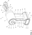
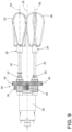
FIG. 1 is a top perspective view of a hand-held mixer; -
FIG. 2 is a side elevational view of a hand-held mixer that includes first and second beaters in engaged conditions and a battery pack in a docked condition; -
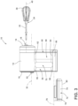
FIG. 3 is a side elevational view of a hand-held mixer that includes first and second beaters in disengaged conditions and a battery pack in an undocked condition; -
FIG. 4 is a perspective view of a hand-held mixer that illustrates internal components of the hand-held mixer; -
FIG. 5 is a back elevational view of a hand-held mixer that includes an ejector button and a rotary control ring that encircles the ejector button; -
FIG. 6 is a cross-sectional view of the hand-held mixer ofFIG. 5 taken at line VI-VI; -
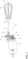
FIG. 7 is a side elevational view of a motor, a gearbox, and first and second beaters of a hand-held mixer; -
FIG. 8 is a front elevational view of a motor, a gearbox, and first and second beaters of a hand-held mixer; -
FIG. 9 is a plan view of a motor, a gearbox, and first and second beaters of a hand-held mixer; -
FIG. 10 is a front elevational view of a hand-held mixer; and -
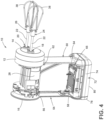
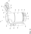
FIG. 11 is a top perspective view of an embodiment of a hand-held mixer; -
FIG. 12 is a side elevational view of a hand-held mixer illustrating a battery pack in an undocked condition; and -
FIG. 13 is a bottom perspective view of a hand-held mixer, illustrating a battery receptacle and a battery pack in an undocked condition. - The components in the figures are not necessarily to scale, emphasis instead being placed upon illustrating the principles described herein.
- For purposes of description herein, the terms "upper," "lower," "right," "left," "rear," "front," "vertical," "horizontal," and derivatives thereof shall relate to the disclosure as oriented in
FIG. 10 . Unless stated otherwise, the term "front" shall refer to the surface of the element closer to an intended viewer, and the term "rear" shall refer to the surface of the element further from the intended viewer. However, it is to be understood that the disclosure may assume various alternative orientations, except where expressly specified to the contrary. It is also to be understood that the specific devices and processes illustrated in the attached drawings, and described in the following specification, are psimply exemplary embodiments of the inventive concepts defined in the appended claims. Hence, specific dimensions and other physical characteristics relating to the embodiments disclosed herein are not to be considered as limiting, unless the claims expressly state otherwise. - The terms "including," "comprises," "comprising," or any other variation thereof, are intended to cover a non-exclusive inclusion, such that a process, method, article, or apparatus that comprises a list of elements does not include only those elements but may include other elements not expressly listed or inherent to such process, method, article, or apparatus. An element preceded by "comprises a ... " does not, without more constraints, preclude the existence of additional identical elements in the process, method, article, or apparatus that comprises the element.
- As used herein, the term "and/or," when used in a list of two or more items, means that any one of the listed items can be employed by itself, or any combination of two or more of the listed items can be employed. For example, if a composition is described as containing components A, B, and/or C, the composition can contain A alone; B alone; C alone; A and B in combination; A and C in combination; B and C in combination; or A, B, and C in combination.
- In this document, relational terms, such as "first" and "second," "top" and "bottom," and the like, are used solely to distinguish one entity or action from another entity or action, without necessarily requiring or implying any actual such relationship or order between such entities or actions.
- The terms "substantial," "substantially," and variations thereof as used herein are intended to note that a described feature is equal or approximately equal to a value or description. For example, a "substantially planar" surface is intended to denote a surface that is planar or approximately planar. Moreover, "substantially" is intended to denote that two values are equal or approximately equal. In some embodiments, "substantially" may denote values within about 10% of each other, such as within about 5% of each other, or within about 2% of each other.
- As used herein, the terms "the," "a," or "an," mean "at least one," and should not be limited to "only one" unless explicitly indicated to the contrary. Thus, for example, reference to "a component" includes embodiments having two or more such components unless the context clearly indicates otherwise.
- Referring now to
FIGS. 1-10 ,reference numeral 10 generally designates a hand-held mixer. The hand-heldmixer 10 includes ahousing 12. Thehousing 12 includes afront side 14 and arear side 16 that is opposite thefront side 14. As illustrated inFIG. 4 , thefront side 14 of thehousing 12 defines afirst aperture 18 and asecond aperture 20. As described further herein, the first andsecond apertures shafts 22 of first andsecond beaters - The hand-held
mixer 10 further includes amotor 28. As illustrated inFIGS. 4 and6 , themotor 28 is positioned within thehousing 12 of the hand-heldmixer 10. In various implementations, themotor 28 is configured to drive rotation of adrive shaft 30 of themotor 28 about a drive shaft axis ofrotation 32, as illustrated inFIGS. 6 and9 . The drive shaft axis ofrotation 32 may extend through the front andrear sides housing 12. A variety of types ofmotors 28 configured to drive rotation of thedrive shaft 30 about the drive shaft axis ofrotation 32 are contemplated. - Referring now to
FIGS. 6-9 , the hand-heldmixer 10 includes agearbox 34. As illustrated inFIG. 6 , thegearbox 34 is disposed within thehousing 12 of the hand-heldmixer 10. In various implementations, thegearbox 34 is positioned between thefront side 14 of thehousing 12 and themotor 28 of the hand-heldmixer 10. Thegearbox 34 includes a plurality ofgears 36. A variety of types ofgears 36 are contemplated. In the embodiment illustrated inFIGS. 7-9 , thegearbox 34 includes a plurality ofhelical gears 36. The plurality ofgears 36 of thegearbox 34 are configured to interlock and are rotated by thedrive shaft 30 which is rotated by themotor 28. As described further herein, the plurality ofgears 36 are configured to convert rotational movement of thedrive shaft 30 to rotational movement of the first andsecond beaters - Referring still to
FIGS. 6-9 , the hand-heldmixer 10 can include afirst beater hub 35 and asecond beater hub 37. Thefirst beater hub 35 and thesecond beater hub 37 are operably engaged with themotor 28. The first andsecond beater hubs motor 28 via thegearbox 34. Thefirst beater hub 35 and thesecond beater hub 37 can receive portions of first andsecond beaters mixer 10. Further, the first andsecond beater hubs second beaters second beater hubs - Referring now to
FIGS. 1-10 , the hand-heldmixer 10 includes afirst beater 24 and asecond beater 26. The first andsecond beaters beater head 38 and ashaft 22 that is coupled to thebeater head 38. As illustrated inFIGS. 2 and3 , thefirst beater 24 is operable between an engaged condition and a disengaged condition. In the engaged condition, theshaft 22 of thefirst beater 24 is partially inserted into thefirst aperture 18 that is defined by thefront side 14 of thehousing 12, as illustrated inFIGS. 2 and4 . Further, in the engaged condition, theshaft 22 of thefirst beater 24 is operably engaged with themotor 28 via thegearbox 34, such that rotation of thedrive shaft 30 about the drive shaft axis ofrotation 32 causes thefirst beater 24 to rotate about a first beater axis ofrotation 40. As illustrated inFIG. 9 , the first beater axis ofrotation 40 is substantially parallel to the drive shaft axis ofrotation 32. In the disengaged condition of thefirst beater 24, theshaft 22 is not operably engaged with themotor 28 via thegearbox 34. Further, theshaft 22 of thefirst beater 24 is removable from thefirst aperture 18 defined by thehousing 12 in the disengaged condition, as illustrated inFIG. 3 . - Referring still to
FIGS. 1-10 , thesecond beater 26 of the hand-heldmixer 10 is operable between an engaged condition and a disengaged condition. In the engaged condition of thesecond beater 26, theshaft 22 of thesecond beater 26 is partially inserted into thesecond aperture 20 that is defined by thefront side 14 of thehousing 12, as illustrated inFIGS. 2 and4 . Further, thesecond beater 26 is operably engaged with themotor 28 of the hand-heldmixer 10 via thegearbox 34 while thesecond beater 26 is in the engaged condition, such that rotation of thedrive shaft 30 about the drive shaft axis ofrotation 32 causes thesecond beater 26 to rotate about a second beater axis ofrotation 42. As illustrated inFIG. 9 , the second beater axis ofrotation 42 is substantially parallel to the drive shaft axis ofrotation 32 and the first beater axis ofrotation 40. In the disengaged condition of thesecond beater 26, as illustrated inFIG. 3 , theshaft 22 of thesecond beater 26 is not operably engaged with themotor 28 via thegearbox 34, and theshaft 22 is removable from thesecond aperture 20 defined by thehousing 12. It is contemplated that the hand-heldmixer 10 can include more or fewer beaters, in some implementations. For example, the hand-heldmixer 10 can include four beaters in some embodiments. - Referring now to
FIGS. 1 ,5 , and6 , the hand-heldmixer 10 can include anejector button 44. As illustrated inFIGS. 1 and5 , theejector button 44 can be positioned at therear side 16 of thehousing 12. Theejector button 44 is configured to be depressed to prompt the first andsecond beaters FIG. 3 , from the engaged conditions, as illustrated inFIG. 2 , respectively. In various embodiments, theejector button 44 is configured to be depressed in a direction that is parallel to at least one of the first beater axis ofrotation 40, the second beater axis ofrotation 42, and the drive shaft axis ofrotation 32. In the embodiment illustrated inFIGS. 1 ,5 , and6 , theejector button 44 is configured to be depressed toward thefront side 14 of thehousing 12 to release the first andsecond beaters motor 28. As illustrated inFIG. 6 , aspring 46 is coupled to theejector button 44, such that theejector button 44 is spring-loaded. It is contemplated that theejector button 44 may be continually biased toward the undepressed position, as illustrated inFIG. 1 , by thespring 46. - Referring now to
FIGS. 1 and5 , the hand-heldmixer 10 can include acontrol feature 48 for controlling operation of themotor 28. In the embodiment illustrated inFIGS. 1 and5 , thecontrol feature 48 is arotary control ring 50. As illustrated, therotary control ring 50 is disposed at therear side 16 of thehousing 12 and encircles theejector button 44 of the hand-heldmixer 10. In the illustrated embodiment, therotary control ring 50 includes atab 52 that extends outward from therotary control ring 50 away from thefront side 14 of thehousing 12. Thetab 52 may provide a handhold for a user adjusting therotary control ring 50, and may indicate which setting themotor 28 is configured to be operated on based on the position of thetab 52. - The
rotary control ring 50 is operable to move rotationally about theejector button 44 to control operation of themotor 28. For example, in an exemplary embodiment, therotary control ring 50 may be rotated clockwise from the perspective ofFIG. 5 about theejector button 44 to turn on themotor 28 and/or intensify operation of themotor 28. A variety of types of control features are contemplated. Further, it is contemplated that therotary control ring 50 may partially encircle theejector button 44, in some implementations. For example, therotary control ring 50 may extend around a majority of a circumference of theejector button 44, in some implementations. In some embodiments of the hand-heldmixer 10, if thecontrol feature 48 is switched to an "on" setting while themotor 28 is disconnected from a power source (e.g., abattery 74 is not connected to the hand-held mixer 10), subsequent connection of themotor 28 to the power source does not cause themotor 28 to turn on. Instead, once the power source is connected, switching thecontrol feature 48 to an "off" setting and then switching thecontrol feature 48 back to the "on" setting causes themotor 28 to turn on. As such, unexpected operation of themotor 28 when a power source is connected to the hand-heldmixer 10 may be avoided. - Referring now to
FIGS. 1-6 and10 , the hand-heldmixer 10 includes afirst pillar 54. Thefirst pillar 54 is coupled to thehousing 12 at a first pillarproximal end 56. Thefirst pillar 54 extends outward from the first pillarproximal end 56 to a first pillardistal end 58 that is distal from thehousing 12. The hand-heldmixer 10 further includes asecond pillar 60 that is coupled to thehousing 12. Thesecond pillar 60 is coupled to thehousing 12 at a second pillarproximal end 62 and extends outward from thehousing 12 to a second pillardistal end 64. As illustrated inFIGS. 1-3 , thesecond pillar 60 is nearer than thefirst pillar 54 to thefront side 14 of thehousing 12. Further, as illustrated inFIGS. 2 and3 , thesecond pillar 60 may be larger than thefirst pillar 54. - Referring still to
FIGS. 1-6 and10 , the hand-heldmixer 10 includes abattery receptacle 66. Thebattery receptacle 66 is coupled to the first and second pillar distal ends 58, 64 of the first andsecond pillars FIGS. 2 and3 , thebattery receptacle 66 extends between the first pillardistal end 58 and the second pillardistal end 64. In various embodiments, thebattery receptacle 66, thefirst pillar 54, thehousing 12, and thesecond pillar 60 form aloop 68 that defines ahandle aperture 70. In operation of the hand-heldmixer 10, a portion of a hand of a user may extend through thehandle aperture 70 defined by the hand-heldmixer 10, as the user grabs thefirst pillar 54 to operate the hand-heldmixer 10. - Referring still to
FIGS. 1-6 and10 , thebattery receptacle 66 may be configured to receive abattery pack 72 for powering themotor 28 of the hand-heldmixer 10. As illustrated inFIG. 6 , wires and other electrical components may extend from thebattery receptacle 66 to themotor 28 within thehousing 12 through the interior of the first and/orsecond pillars mixer 10. As described further herein, thebattery receptacle 66 may be configured to receive thebattery pack 72 of the hand-heldmixer 10. It is contemplated that at least a portion of thehousing 12, the first and/orsecond pillars battery receptacle 66 may be integrally coupled to each other. For example, in some embodiments, the hand-heldmixer 10 can include an outer shell that forms at least a portion of thehousing 12, the first andsecond pillars battery receptacle 66. - Referring now to
FIGS. 1-6 and10 , the hand-heldmixer 10 includes thebattery pack 72. Thebattery pack 72 includes abattery 74 that is configured to power themotor 28 of the hand-heldmixer 10. As illustrated inFIGS. 2 and3 , thebattery pack 72 is operable between a docked condition, as illustrated inFIG. 2 , and an undocked condition, as illustrated inFIG. 3 . In the docked condition of thebattery pack 72, thebattery pack 72 is engaged with thebattery receptacle 66 to provide power to themotor 28 of the hand-heldmixer 10. In the undocked condition, thebattery pack 72 is disengaged from thebattery receptacle 66, as illustrated inFIG. 3 . - As further illustrated in
FIG. 3 , thebattery pack 72 is operable to move from the undocked condition to the docked condition along abattery pack axis 76. In some implementations, thebattery pack axis 76 may be substantially parallel to the drive shaft axis ofrotation 32, the first beater axis ofrotation 40, and/or the second beater axis ofrotation 42. In other words, thebattery pack 72 may move between the docked and undocked conditions in a direction that is substantially parallel to the drive shaft axis ofrotation 32, the first beater axis ofrotation 40, and/or the second beater axis ofrotation 42, in some implementations. In the embodiment illustrated inFIGS. 2 and3 , thebattery pack 72 moves from the undocked condition to the docked condition along thebattery pack axis 76, which is substantially parallel to the drive shaft axis ofrotation 32, first beater axis ofrotation 40, and second beater axis ofrotation 42, such that thebattery pack 72 is nearer to thefront side 14 of thehousing 12 in the docked condition than in the undocked condition. In other words, thebattery 74 moves toward the front of the hand-heldmixer 10 as thebattery 74 moves along thebattery pack axis 76 from the undocked condition to the docked condition. In various implementations, thebattery receptacle 66 may guide the direction of movement of thebattery pack 72 along thebattery pack axis 76. - Referring now to
FIGS. 2 and3 , in some implementations, a battery pack handle 78 is coupled to thebattery pack 72. In the embodiment illustrated inFIGS. 2 and3 , the battery pack handle 78 is pivotably coupled to a rear portion of thebattery pack 72. The battery pack handle 78 is operable to pivot from a stowed position, as illustrated inFIG. 2 , to a use position, as illustrated inFIG. 3 . Pivoting the battery pack handle 78 from the stowed position to the use position may reduce the amount of force that restricts movement of thebattery pack 72 from the docked condition to the undocked condition. - In various embodiments, the
battery pack 72 is the furthest portion of the hand-heldmixer 10 from thehousing 12 in the docked condition of thebattery pack 72. Further, thebattery pack 72 includes abottom surface 80 that is configured to rest upon a level surface, such as a counter, such that the hand-heldmixer 10 sits upright (i.e., in an upright position) with the first beater axis ofrotation 40 extending substantially horizontally, as illustrated inFIG. 2 . The first and second beater axes ofrotation mixer 10. For example, from the perspective of a viewer ofFIG. 2 , rotating the hand-heldmixer 10 ofFIG. 2 clockwise 90 degrees such that the first beater axis ofrotation 40 extends substantially vertically would depict the hand-heldmixer 10 in the use position. - As can be appreciated, the use of the
battery 74 to power themotor 28 is such that the hand-heldmixer 10 described herein is operable without having to plug the hand-heldmixer 10 into an external power source (such as a wall outlet or the like) and results in the disclosed hand-heldmixer 10 being characterized as "cordless". In this manner, the hand-heldmixer 10 can be placed and operated in any convenient location along the counter space provided within the kitchen, regardless of the proximity of such location to a power outlet or another available power source. Additionally, as thebattery pack 72 is operable to enter the undocked condition when thebattery 74 of thebattery pack 72 is depleted, thebattery pack 72 can be undocked from thebattery receptacle 66 and docked to a compatible charger having mechanical components and/or terminals similar to thebattery receptacle 66 of the present hand-heldmixer 10. An example of such a charger is described in the pending, commonly-ownedU.S. Provisional Patent Application Nos. 63/315,355, filed March 1, 2022 63/407,933, filed September 19, 2022 - The
battery 74 and corresponding electronic circuitry for controlling the operation of the hand-heldmixer 10, including the operation of themotor 28, can be configured according to an architecture using a voltage in the range of about 10-20 volts, and in oneimplementation 20 volts, with it being understood that the actual voltage supplied and utilized may vary within a range around the described desired operating voltage according to factors generally understood in the art. In this manner, thebattery 74 can be a five-cell 20-volt battery, although other configurations are possible. In general, such a voltage may be sufficient for operation of the hand-heldmixer 10 including operation of themotor 28, which is generally understood to be a direct-current (DC) motor, and in one aspect a brushless DC motor, at an acceptable torque for typically-accepted use as a hand-held mixer within an acceptable operating speed. - In various embodiments, the first and/or
second pillars housing 12, in which themotor 28 is disposed, and thebattery receptacle 66, to which thebattery pack 72 is configured to be docked, may result in the hand-heldmixer 10 having an ergonomic center of mass that allows for convenient handling of the hand-heldmixer 10 during use. Thegearbox 34 being configured, such that the drive shaft axis ofrotation 32 is substantially parallel to the first and second beater axes ofrotation motor 28 andgearbox 34 to be disposed within thehousing 12, which results in thehousing 12 end of the hand-heldmixer 10 being relatively heavy. The weight of thehousing 12 end of the hand-heldmixer 10 is balanced by the weight of thebattery pack 72, which is distal from thehousing 12. In operation of the hand-heldmixer 10, the drive shaft axis ofrotation 32 and first and second beater axes ofrotation front side 14 of thehousing 12 faces substantially vertically-downward, as the first andsecond beaters second pillars housing 12 to thebattery pack 72 that is distal from thehousing 12. Accordingly, for a user gripping thefirst pillar 54 of the hand-heldmixer 10 in this orientation, the weight of thebattery pack 72 can aid in balancing out the weight of thehousing 12 and the components disposed therein. - Referring now to
FIGS. 11-13 , another example of a hand-heldmixer 110 is illustrated. In reference to the example of the hand-heldmixer 110 illustrated inFIGS. 11-13 , the numbering of elements of the hand-heldmixer 110 are increased by 100 relative to the numbering of similar elements of the example hand-heldmixer 10 provided inFIGS. 1-10 . The illustrated example of the hand-heldmixer 110 includes thehousing 112, thefirst pillar 154 that is coupled to thehousing 112 at the first pillarproximal end 156, and thesecond pillar 160 that is coupled to thehousing 112 at the second pillarproximal end 162. Thesecond pillar 160 is larger than thefirst pillar 154, and can cooperate with thehousing 112 to house themotor 128 and/or thegearbox 134. In the illustrated example, thegearbox 134 may be engaged with thedrive shaft 130 of themotor 128, such that thegearbox 134 converts rotation of thedrive shaft 130 about the drive shaft axis ofrotation 132 to rotational movement about another axis that is substantially perpendicular to the drive shaft axis ofrotation 132, as described further herein. - As illustrated in
FIG. 11 , the hand-heldmixer 110 includes the first andsecond beaters second beaters motor 128 via thegearbox 134, such that rotation of thedrive shaft 130 about the drive shaft axis ofrotation 132 causes thefirst beater 124 to rotate about the first beater axis ofrotation 140 and thesecond beater 126 to rotate about the second beater axis ofrotation 142. As illustrated inFIG. 12 , the first and second beater axes ofrotation rotation 132. As illustrated inFIG. 11 , the first andsecond beaters shafts 122 and beater heads 138, respectively. - Referring still to
FIGS. 11-13 , thefirst pillar 154 extends outward from the first pillarproximal end 156 to the first pillardistal end 158 that is distal from thehousing 112. Further, thesecond pillar 160 extends outward from thehousing 112 to the second pillardistal end 164. Thesecond pillar 160 is nearer than thefirst pillar 154 to thefront side 114 of thehousing 112. As illustrated inFIG. 12 , thefront side 114 of thehousing 112 is opposite therear side 116 of thehousing 112. In the illustrated example, the first and second pillar distal ends 158, 164 are spaced apart from each other, such that thefirst pillar 154 is configured to serve as an operating handle for the hand-heldmixer 110. As further shown inFIGS. 11-13 , thefirst pillar 154 is configured to extend generally flush, or continuously, with a corresponding outer surface of thehousing 112 to define a generally uniform appearance between thehousing 112 and thefirst pillar 154. In the illustrated example, thehousing 112 and thefirst pillar 154 are generally defined by two distinct structures that are assembled together with themotor 128 andgearbox 134 therein. It is contemplated, however, that thehousing 112 and thefirst pillar 154 may be generally defined by respective portions of a single structure, with the internal components of the hand-heldmixer 110 being assembled within such structure by an alternative configuration thereof. As further illustrated inFIG. 13 , thefirst pillar 154 can include theejector button 144 and thecontrol feature 148. - Referring still to
FIGS. 11-13 , the hand-heldmixer 110 includes thebattery receptacle 166. As illustrated inFIG. 12 , thebattery receptacle 166 is coupled to the second pillardistal end 164 and is in a spaced-relationship with the first pillardistal end 158. It is contemplated that thebattery receptacle 66 may extend between the first pillardistal end 58 and the second pillardistal end 64, as illustrated inFIGS. 1-6 and10 , in some implementations. Thebattery receptacle 66 is configured to receive thebattery pack 72 for powering themotor 28 of the hand-heldmixer 10. - As illustrated in
FIGS. 11 and12 , thebattery pack 172 is operable between the docked condition, as illustrated inFIG. 11 , and the undocked condition, as illustrated inFIG. 12 . In the docked condition of thebattery pack 172, thebattery pack 172 is engaged with thebattery receptacle 166 to provide power to themotor 128 of the hand-heldmixer 110. In the undocked condition, thebattery pack 172 is disengaged from thebattery receptacle 166, as illustrated inFIGS. 12 and13 . - As further illustrated in
FIG. 12 , thebattery pack 172 is operable to move from the undocked condition to the docked condition along thebattery pack axis 176. In some implementations, thebattery pack axis 176 may be substantially parallel to the drive shaft axis ofrotation 132. In some implementations, thebattery pack axis 176 may be substantially perpendicular to the first beater axis ofrotation 140, and/or the second beater axis ofrotation 142. In the example illustrated inFIGS. 11-13 , thebattery pack 172 is configured to move between the docked and undocked conditions in a direction that is substantially parallel to the drive shaft axis ofrotation 132 and substantially perpendicular to the first beater axis ofrotation 140 and the second beater axis ofrotation 142. In various implementations, thebattery receptacle 166 may guide the direction of movement of thebattery pack 172 along thebattery pack axis 176. - In various embodiments, the
battery pack 172 is the farthest portion of the hand-heldmixer 110 from thehousing 112 in the docked condition of thebattery pack 172. Further, thebattery pack 172 includes abottom surface 180 that is configured to rest upon a level surface, such as a counter, such that the hand-heldmixer 110 sits upright (i.e., in the upright position) with the first and second beater axes ofrotation FIG. 12 . The first and second beater axes ofrotation mixer 110. For example, from the perspective of a viewer ofFIG. 12 , rotating the hand-heldmixer 110 ofFIG. 12 clockwise 90 degrees such that the first and second beater axes ofrotation mixer 110 in the use position. - The
battery 174 and corresponding electronic circuitry for controlling operation of the example of the hand-heldmixer 110 illustrated inFIGS. 11-13 , including the operation of themotor 128, can be configured according to an architecture using a voltage of about 12 volts, with it being understood that the actual voltage supplied and utilized may vary within a range around the described desired operating voltage according to factors generally understood in the art. Accordingly, a "12-volt" battery as used herein refers to a general classification of battery that would be understood by a person of ordinary skill in the art to have an output that may not be exactly 12 volts due to, for example, fluctuations in power delivery during use or as an effect of the charge condition of cells within the battery. In this respect, thebattery 174 of the example of the hand-heldmixer 110 illustrated inFIGS. 11-13 may be smaller in output relative to the 18-20volt battery 74 described above herein in reference toFIGS. 1-6 and10 . Thesmaller output battery 174 provides a lower current to themotor 128. As such, the 12-volt battery 174 can be smaller in size while still providing the desired duration of power supply and corresponding use of the hand-heldmixer 110. Thebattery receptacle 166 configured to receive the 12-volt battery 174 illustrated inFIGS. 11-13 can, accordingly, be smaller than thebattery receptacle 66 configured to receive the 20-volt battery 74 inFIGS. 1-6 and10 . - As illustrated in
FIGS. 11-13 , thebattery pack 172 is adapted for a snap-fit arrangement with thebattery receptacle 166, wherein thebattery pack 172 is moved toward thebattery receptacle 166 in a direction substantially perpendicular to the first and second beater axes ofrotation battery receptacle 166 engage with aligned terminals of thebattery pack 172 for electrical connection between thebattery 174 and electrical components of the hand-heldmixer 110. As illustrated inFIGS. 11-13 , thebattery pack 172 can include spring-loadedtabs 182. The spring-loadedtabs 182 are biased outwardly but are moved inwardly by initial engagement with corresponding notches in thebattery receptacle 166, as thebattery pack 172 is moved toward the docked condition. Subsequently, thetabs 182 resiliently rebound outward when they have passed beyond the notches to fix thebattery pack 172 in the docked condition. When thebattery pack 172 is to be removed,buttons 184 associated with thetabs 182 can be depressed to move thetabs 182 inward, thereby releasing them from the notches. - According to one aspect of the present disclosure, a hand-held mixer includes a housing, a motor, a gearbox, and first and second beaters. The housing has a front side and a rear side opposite the front side. The motor is positioned within the housing and configured to drive rotation of a drive shaft about a drive shaft axis of rotation. The gearbox has a plurality of gears disposed within the housing and is operably coupled to the motor. The first beater has a beater head and a shaft coupled to the beater head and is operable between an engaged condition and a disengaged condition. In the engaged condition of the first beater, the shaft is partially inserted into a first aperture defined by the front side of the housing and operably engaged with the motor via the gearbox, such that rotation of the drive shaft about the drive shaft axis of rotation causes the first beater to rotate about a first beater axis of rotation that is substantially parallel to the drive shaft axis of rotation. In the disengaged condition of the first beater, the shaft is not operably engaged with the motor via the gearbox and is removable from the first aperture defined by the housing. The second beater has a beater head and a shaft coupled to the beater head. The second beater is operable between an engaged condition and a disengaged condition. In the engaged condition of the second beater, the shaft is partially inserted into a second aperture defined by the front side of the housing and operably engaged with the motor via the gearbox, such that rotation of the drive shaft about the drive shaft axis of rotation causes the second beater to rotate about a second beater axis of rotation that is substantially parallel to the drive shaft axis of rotation and the first beater axis of rotation. In the disengaged condition of the second beater, the shaft is not operably engaged with the motor via the gearbox and is removable from the second aperture defined by the housing.
- According to another aspect of the present disclosure, an ejector button is positioned at the rear side of the housing and is configured to be depressed to prompt the first and second beaters to enter the disengaged conditions from the engaged conditions, respectively.
- According to another aspect of the present disclosure, a rotary control ring encircles the ejector button at the rear side of the housing and is operable to move rotationally about the ejector button to control operation of the motor.
- According to another aspect of the present disclosure, a first pillar is coupled to the housing at a first pillar proximal end and extends outward therefrom to a first pillar distal end, and a second pillar is coupled to the housing at a second pillar proximal end and extends outward therefrom to a second pillar distal end. Further, the second pillar is nearer than the first pillar to the front side of the housing.
- According to another aspect of the present disclosure, a battery receptacle is coupled to the first and second pillar distal ends and extends therebetween, such that the battery receptacle, first pillar, housing, and second pillar form a loop that defines a handle aperture.
- According to yet another aspect of the present disclosure, a battery pack has a battery for powering the motor and is operable between a docked condition and an undocked condition. In the docked condition, the battery pack is engaged with the battery receptacle to provide power to the motor. In the undocked condition, the battery pack is disengaged from the battery receptacle.
- According to another aspect of the present disclosure, a hand-held mixer includes a housing, first and second pillars, a motor, a gearbox, first and second beaters, a battery receptacle, and a battery pack. The housing has a front side and a rear side opposite the front side. The first pillar is coupled to the housing at a first pillar proximal end and extends outward therefrom to a first pillar distal end. The second pillar is coupled to the housing at a second pillar proximal end and extends outward therefrom to a second pillar distal end. Further, the second pillar is nearer than the first pillar to the front side of the housing. The motor is positioned within at least one of the housing and the second pillar and is configured to drive rotation of a drive shaft about a drive shaft axis of rotation. The gearbox has a plurality of gears disposed within at least one of the housing and the second pillar and is operably coupled to the motor. The first beater has a beater head and a shaft coupled to the beater head and is operable between an engaged condition and a disengaged condition. In the engaged condition of the first beater, the shaft is partially inserted into a first aperture defined by the front side of the housing and operably engaged with the motor via the gearbox, such that rotation of the drive shaft about the drive shaft axis of rotation causes the first beater to rotate about a first beater axis of rotation that is substantially perpendicular to the drive shaft axis of rotation. In the disengaged condition of the first beater, the shaft is not operably engaged with the motor via the gearbox and is removable from the first aperture defined by the housing. The second beater has a beater head and a shaft coupled to the beater head. The second beater is operable between an engaged condition and a disengaged condition. In the engaged condition of the second beater, the shaft is partially inserted into a second aperture defined by the front side of the housing and operably engaged with the motor via the gearbox, such that rotation of the drive shaft about the drive shaft axis of rotation causes the second beater to rotate about a second beater axis of rotation that is substantially perpendicular to the drive shaft axis of rotation and substantially parallel to the first beater axis of rotation. In the disengaged condition of the second beater, the shaft is not operably engaged with the motor via the gearbox and is removable from the second aperture defined by the housing. The battery receptacle is coupled to the second pillar distal end. The battery pack includes a 12 V battery for powering the motor. The battery pack is operable between a docked condition, wherein the battery pack is engaged with the battery receptacle to provide power to the motor, and an undocked condition, wherein the battery pack is disengaged from the battery receptacle. The battery pack moves along a battery pack axis that is substantially parallel to the drive shaft axis of rotation from the undocked condition to the docked condition.
- According to another aspect of the present disclosure, a hand-held mixer includes a housing having a front side and a rear side opposite the front side. A pillar is coupled to the housing at a pillar proximal end and extends outward therefrom to a pillar distal end. A motor is positioned within at least one of the housing and the pillar. A first beater hub removably receives a first beater having a beater head and a shaft coupled to the beater head. The first beater hub is operably engaged with the motor such that, in an engaged condition of the first beater, operation of the motor drives rotation of the first beater about a first beater axis of rotation. A battery receptacle is disposed at the pillar distal end and configured to receive a battery pack that has a battery for powering the motor such that the battery pack is operable between a docked condition and an undocked condition. In the docked condition, the battery pack is engaged with the battery receptacle to provide power to the motor. In an undocked condition, the battery pack is disengaged from the battery receptacle. The battery pack moves along a battery pack axis that is substantially perpendicular to the first beater axis of rotation from the undocked condition to the docked condition.
- According to another aspect of the present disclosure, the first beater is operable between an engaged condition and a disengaged condition. In the engaged condition, the shaft is partially inserted into a first aperture defined by the first beater hub and exposed on the front side of the housing so as to be operably engaged with the motor. In the disengaged condition, the shaft is removed from the first aperture so as to be operably disengaged from the motor.
- According to another aspect of the present disclosure, a second beater hub removably receives a second beater having a beater head and a shaft coupled to the beater head. The second beater hub is operably engaged with the motor such that, in an engaged condition of the second beater, operation of the motor drives rotation of the second beater about a second beater axis of rotation.
- According to another aspect of the present disclosure, a gearbox has a plurality of gears disposed within at least one of the housing and the pillar and being operably coupled to the motor. The first beater hub is operably engaged with the motor via the gearbox.
- According to another aspect of the present disclosure, the motor includes a drive shaft that is operably coupled with the gearbox and configured to rotate about a drive shaft axis of rotation, and the drive shaft axis of rotation is substantially perpendicular to the first beater axis of rotation.
- According to another aspect of the present disclosure, the drive shaft axis of rotation is substantially parallel to the battery pack axis.
- According to another aspect of the present disclosure, the battery pack includes a bottom surface that is configured to rest upon a level surface to maintain said hand-held mixer in an upright position. The first beater axis of rotation extends substantially horizontally.
- According to another aspect of the present disclosure, the motor includes a drive shaft configured to rotate about a drive shaft axis of rotation, and the drive shaft axis of rotation is substantially vertical in the upright position of said hand-held mixer.
- According to another aspect of the present disclosure, the battery pack is the farthest portion of said hand-held mixer from the housing in the docked condition of the battery pack.
- According to another aspect of the present disclosure, the battery receptacle includes at least one notch that engages with at least one spring-loaded tab of the battery pack. The at least one spring-loaded tab is biased outwardly and configured to be moved inwardly by initial engagement with the at least one notch in the battery receptacle as the battery pack is moved toward the docked condition.
- According to another aspect of the present disclosure, the at least one tab is configured to resiliently rebound outward to fix the battery pack in the docked condition.
- According to another aspect of the present disclosure, the pillar at least partially houses the motor.
- According to another aspect of the present disclosure, the pillar is a first pillar, and said hand-held mixer further comprises a second pillar configured as a grab handle that extends outward from the housing.
- According to another aspect of the present disclosure, the first pillar is larger than the second pillar.
- According to another aspect of the present disclosure, the battery is a 12-volt battery.
- According to another aspect of the present disclosure, a hand-held mixer includes a housing having a front side and a rear side opposite the front side. A first pillar is coupled to the housing at a first pillar proximal end and extends outward therefrom to a first pillar distal end. A second pillar is coupled to the housing at a second pillar proximal end and extends outward therefrom to a second pillar distal end. A motor is positioned within at least one of the housing and the second pillar. A first beater has a beater head and a shaft coupled to the beater head. The first beater is operably engaged with the motor in a removably engaged condition of the first beater with the housing, such that operation of the motor is configured to drive rotation of the first beater about a first beater axis of rotation. A battery receptacle is disposed at the second pillar distal end. Further, a battery pack has a battery for powering the motor and is operable between a docked condition and an undocked condition. In the docked condition, the battery pack is engaged with the battery receptacle to provide power to the motor. In the undocked condition, the battery pack is disengaged from the battery receptacle. The battery pack moves along a battery pack axis that is substantially perpendicular to the first beater axis of rotation from the undocked condition to the docked condition.
- According to another aspect of the present disclosure, the motor includes a drive shaft that is operable to rotate about a drive shaft axis of rotation, and the drive shaft axis of rotation is substantially perpendicular to the first beater axis of rotation.
- According to another aspect of the present disclosure, the drive shaft axis of rotation is substantially parallel to the battery pack axis.
- According to another aspect of the present disclosure, the battery pack includes a bottom surface that is configured to rest upon a level surface to maintain said hand-held mixer in an upright position. The first beater axis of rotation extends substantially horizontally.
- According to another aspect of the present disclosure, the motor includes a drive shaft configured to rotate about a drive shaft axis of rotation, and the drive shaft axis of rotation is substantially vertical in the upright position of said hand-held mixer.
- According to another aspect of the present disclosure, the second pillar at least partially houses the motor.
- It will be understood by one having ordinary skill in the art that construction of the described disclosure and other components is not limited to any specific material. Other exemplary embodiments of the disclosure disclosed herein may be formed from a wide variety of materials, unless described otherwise herein.
- For purposes of this disclosure, the term "coupled" (in all of its forms, couple, coupling, coupled, etc.) generally means the joining of two components (electrical or mechanical) directly or indirectly to one another. Such joining may be stationary in nature or movable in nature. Such joining may be achieved with the two components (electrical or mechanical) and any additional intermediate members being integrally formed as a single unitary body with one another or with the two components. Such joining may be permanent in nature or may be removable or releasable in nature unless otherwise stated.
- It is also important to note that the construction and arrangement of the elements of the disclosure as shown in the exemplary embodiments is illustrative only. Although only a few embodiments of the present innovations have been described in detail in this disclosure, those skilled in the art who review this disclosure will readily appreciate that many modifications are possible (e.g., variations in sizes, dimensions, structures, shapes and proportions of the various elements, values of parameters, mounting arrangements, use of materials, colors, orientations, etc.) without materially departing from the novel teachings and advantages of the subject matter recited. For example, elements shown as integrally formed may be constructed of multiple parts or elements shown as multiple parts may be integrally formed, the operation of the interfaces may be reversed or otherwise varied, the length or width of the structures and/or members or connectors or other elements of the system may be varied, and/or the nature or number of adjustment positions provided between the elements may be varied. It should be noted that the elements and/or assemblies of the system may be constructed from any of a wide variety of materials that provide sufficient strength or durability, in any of a wide variety of colors, textures, and combinations. Accordingly, all such modifications are intended to be included within the scope of the present innovations. Other substitutions, modifications, changes, and omissions may be made in the design, operating conditions, and arrangement of the desired and other exemplary embodiments without departing from the spirit of the present innovations.
- It will be understood that any described processes or steps within described processes may be combined with other disclosed processes or steps to form structures within the scope of the present disclosure. The exemplary structures and processes disclosed herein are for illustrative purposes and are not to be construed as limiting.
Claims (15)
- A hand-held mixer (10, 110), comprising:a housing (12, 112) having a front side (14, 114) and a rear side (16, 116) opposite the front side (14, 114);a pillar (60, 160) that is coupled to the housing (12, 112) at a pillar proximal end (62, 162) and extends outward therefrom to a pillar distal end (64, 164);a motor (28, 128) that is positioned within at least one of the housing (12, 112) and the pillar (60, 160);a first beater hub (35) removably receiving a first beater (24, 124) having a beater head (38, 138) and a shaft (22, 122) coupled to the beater head (38, 138), the first beater hub (35) being operably engaged with the motor (28, 128) such that, in an engaged condition of the first beater (24, 124), operation of the motor (28, 128) drives rotation of the first beater (24, 124) about a first beater axis of rotation (40, 140); anda battery receptacle (66, 166) disposed at the pillar distal end (64, 164) and configured to receive a battery pack (72, 172) having a battery (74, 174) for powering the motor (28, 128) such that the battery pack (72, 172) is operable between a docked condition, wherein the battery pack (72, 172) is engaged with the battery receptacle (66, 166) to provide power to the motor (28, 128), and an undocked condition, wherein the battery pack (72, 172) is disengaged from the battery receptacle (66, 166), and wherein the battery pack (72, 172) moves along a battery pack axis (76, 176) that is substantially perpendicular to the first beater axis of rotation (40, 140) from the undocked condition to the docked condition.
- The hand-held mixer (10, 110) of claim 1, wherein the first beater (24, 124) is operable between an engaged condition, wherein the shaft (22, 122) is partially inserted into a first aperture (18) defined by the first beater hub (35) and exposed on the front side (14, 114) of the housing (12, 112) so as to be operably engaged with the motor (28, 128), and a disengaged condition, wherein the shaft (22, 122) is removed from the first aperture (18) so as to be operably disengaged from the motor (28, 128).
- The hand-held mixer (10, 110) of either of claim 1 or claim 2, further comprising:
a second beater hub (37) removably receiving a second beater (26, 126) having a beater head (38, 138) and a shaft (22, 122) coupled to the beater head (38, 138), the second beater hub (37) being operably engaged with the motor (28, 128) such that, in an engaged condition of the second beater (26, 126), operation of the motor (28, 128) drives rotation of the second beater (26, 126) about a second beater axis of rotation (42, 142). - The hand-held mixer (10, 110) of any one of claims 1-3, further comprising:
a gearbox (34, 134) having a plurality of gears (36) disposed within at least one of the housing (12, 112) and the pillar (60, 160) and being operably coupled to the motor (28, 128), wherein the first beater hub (35) is operably engaged with the motor (28, 128) via the gearbox (34, 134). - The hand-held mixer (10, 110) of claim 4, wherein the motor (28, 128) includes a drive shaft (30, 130) that is operably coupled with the gearbox (34, 134) and configured to rotate about a drive shaft axis of rotation (32, 132), and wherein the drive shaft axis of rotation (32, 132) is substantially parallel to the battery pack axis (76, 176).
- The hand-held mixer (110) of claim 5, wherein the drive shaft axis of rotation (32, 132) is substantially vertical in the upright position of said hand-held mixer (10, 110).
- The hand-held mixer (10, 110) of any one of previous claims, wherein the battery pack (72, 172) includes a bottom surface (80, 180) that is configured to rest upon a level surface to maintain said hand-held mixer (10, 110) in an upright position, wherein the first beater axis of rotation (40, 140) extends substantially horizontally.
- The hand-held mixer (10, 110) of any one of claims 5- 7, wherein the drive shaft axis of rotation (132) is substantially perpendicular to the first beater axis of rotation (140).
- The hand-held mixer (10, 110) of any one of previous claims, wherein the battery pack (72, 172) is the farthest portion of said hand-held mixer (10, 110) from the housing (12, 112) in the docked condition of the battery pack (72, 172).
- The hand-held mixer (10, 110) of any one of previous claims, wherein the battery receptacle (66, 166) includes at least one notch that engages with at least one spring-loaded tab (182) of the battery pack (72, 172), wherein the at least one spring-loaded tab (182) is biased outwardly and configured to be moved inwardly by initial engagement with the at least one notch in the battery receptacle (66, 166) as the battery pack (72, 172) is moved toward the docked condition.
- The hand-held mixer (10, 110) of claim 10, wherein the at least one spring-loaded tab (182) is configured to resiliently rebound outward to fix the battery pack (72, 172) in the docked condition.
- The hand-held mixer (10, 110) of one of previous claims, wherein the pillar (60, 160) at least partially houses the motor (28, 128).
- The hand-held mixer (10, 110) of any one of previous claims, wherein the pillar (60, 160) is a first pillar (60, 160), and said hand-held mixer (10, 110) further comprises a second pillar (54, 154) configured as a grab handle that extends outward from the housing (12, 112).
- The hand-held mixer (10, 110) of claim 13, wherein the first pillar (60, 160) is larger than the second pillar (54, 154).
- The hand-held mixer (10, 110) of any one of previous claims, wherein the battery (74, 174) is a 12-volt battery (74, 174).
Applications Claiming Priority (3)
| Application Number | Priority Date | Filing Date | Title |
|---|---|---|---|
| US202263315346P | 2022-03-01 | 2022-03-01 | |
| US202263376174P | 2022-09-19 | 2022-09-19 | |
| US18/174,743 US20230277003A1 (en) | 2022-03-01 | 2023-02-27 | Hand-held mixer |
Publications (1)
| Publication Number | Publication Date |
|---|---|
| EP4238461A1 true EP4238461A1 (en) | 2023-09-06 |
Family
ID=85415531
Family Applications (1)
| Application Number | Title | Priority Date | Filing Date |
|---|---|---|---|
| EP23159517.4A Pending EP4238461A1 (en) | 2022-03-01 | 2023-03-01 | Hand-held mixer |
Country Status (2)
| Country | Link |
|---|---|
| US (1) | US20230277003A1 (en) |
| EP (1) | EP4238461A1 (en) |
Citations (2)
| Publication number | Priority date | Publication date | Assignee | Title |
|---|---|---|---|---|
| FR2179539A1 (en) * | 1972-04-11 | 1973-11-23 | Tower Housewares Ltd | |
| US20210345830A1 (en) * | 2018-10-09 | 2021-11-11 | Omar Hamarneh | Food Processing Device |
-
2023
- 2023-02-27 US US18/174,743 patent/US20230277003A1/en active Pending
- 2023-03-01 EP EP23159517.4A patent/EP4238461A1/en active Pending
Patent Citations (2)
| Publication number | Priority date | Publication date | Assignee | Title |
|---|---|---|---|---|
| FR2179539A1 (en) * | 1972-04-11 | 1973-11-23 | Tower Housewares Ltd | |
| US20210345830A1 (en) * | 2018-10-09 | 2021-11-11 | Omar Hamarneh | Food Processing Device |
Non-Patent Citations (1)
| Title |
|---|
| DD WERKSTATT HOLZWERKEN: "Makita Akkuschrauber Reparatur", 11 September 2018 (2018-09-11), XP093065812, Retrieved from the Internet <URL:https://www.youtube.com/watch?v=xUTXPb5XdVk&list=PLJP1r8okK3lOXk7xe3pjngNNBqd1aoo0K> [retrieved on 20230720] * |
Also Published As
| Publication number | Publication date |
|---|---|
| US20230277003A1 (en) | 2023-09-07 |
Similar Documents
| Publication | Publication Date | Title |
|---|---|---|
| US4575255A (en) | Kitchen appliance arrangement with portable unit | |
| US4277181A (en) | Food mixer | |
| US5372420A (en) | Device having rotatable head | |
| CN101052335B (en) | Mixer without electric wire | |
| WO2008047106A1 (en) | A food processor | |
| EP3338604B1 (en) | Handheld kitchen appliance assembly | |
| US20070159917A1 (en) | Pivoting handheld food preparation appliance and associated method | |
| US20030198124A1 (en) | Processing tool attachments for a food mixing device | |
| TWM342130U (en) | Compound food-processor | |
| US4620476A (en) | Multi-purpose kitchen appliance | |
| GB2082713A (en) | Food-processing appliance driving unit | |
| CN101745336A (en) | Mixing device | |
| WO2019147695A1 (en) | Food processor | |
| EP4238461A1 (en) | Hand-held mixer | |
| EP1182954B1 (en) | Tool storage arrangements for domestic appliances | |
| US20050007867A1 (en) | Hand mixer with eccentrically rotating and orbiting attachment | |
| CN116688822A (en) | Hand-held mixer | |
| CN115986869A (en) | Kitchen handheld device, accessory and using method thereof | |
| CN214104226U (en) | Domestic small-size safe convenient mixer | |
| US20240090703A1 (en) | Cordless blending appliance | |
| CN205513827U (en) | Fast dissolving cup | |
| CN205433462U (en) | Cup with rotating base | |
| EP4243239A1 (en) | Charger and battery for cordless appliance | |
| CN205359072U (en) | Rapid mixing cup | |
| CN211432476U (en) | Portable electric auxiliary rotator |
Legal Events
| Date | Code | Title | Description |
|---|---|---|---|
| PUAI | Public reference made under article 153(3) epc to a published international application that has entered the european phase |
Free format text: ORIGINAL CODE: 0009012 |
|
| STAA | Information on the status of an ep patent application or granted ep patent |
Free format text: STATUS: THE APPLICATION HAS BEEN PUBLISHED |
|
| AK | Designated contracting states |
Kind code of ref document: A1 Designated state(s): AL AT BE BG CH CY CZ DE DK EE ES FI FR GB GR HR HU IE IS IT LI LT LU LV MC ME MK MT NL NO PL PT RO RS SE SI SK SM TR |
|
| STAA | Information on the status of an ep patent application or granted ep patent |
Free format text: STATUS: REQUEST FOR EXAMINATION WAS MADE |
|
| 17P | Request for examination filed |
Effective date: 20240306 |
|
| RBV | Designated contracting states (corrected) |
Designated state(s): AL AT BE BG CH CY CZ DE DK EE ES FI FR GB GR HR HU IE IS IT LI LT LU LV MC ME MK MT NL NO PL PT RO RS SE SI SK SM TR |