EP4238459A1 - Cooking vessel - Google Patents
Cooking vessel Download PDFInfo
- Publication number
- EP4238459A1 EP4238459A1 EP23160011.5A EP23160011A EP4238459A1 EP 4238459 A1 EP4238459 A1 EP 4238459A1 EP 23160011 A EP23160011 A EP 23160011A EP 4238459 A1 EP4238459 A1 EP 4238459A1
- Authority
- EP
- European Patent Office
- Prior art keywords
- lower portion
- microwave
- induction
- cooking
- cooking vessel
- Prior art date
- Legal status (The legal status is an assumption and is not a legal conclusion. Google has not performed a legal analysis and makes no representation as to the accuracy of the status listed.)
- Pending
Links
- 238000010411 cooking Methods 0.000 title claims abstract description 138
- 239000000463 material Substances 0.000 claims abstract description 202
- 230000005672 electromagnetic field Effects 0.000 claims abstract description 16
- 230000005670 electromagnetic radiation Effects 0.000 claims abstract description 15
- 238000010521 absorption reaction Methods 0.000 claims abstract description 12
- VYPSYNLAJGMNEJ-UHFFFAOYSA-N Silicium dioxide Chemical compound O=[Si]=O VYPSYNLAJGMNEJ-UHFFFAOYSA-N 0.000 claims description 22
- 229910000859 α-Fe Inorganic materials 0.000 claims description 20
- 235000012239 silicon dioxide Nutrition 0.000 claims description 11
- 239000000377 silicon dioxide Substances 0.000 claims description 11
- 239000003302 ferromagnetic material Substances 0.000 claims description 9
- 239000007769 metal material Substances 0.000 claims description 7
- 229910052782 aluminium Inorganic materials 0.000 claims description 6
- XAGFODPZIPBFFR-UHFFFAOYSA-N aluminium Chemical compound [Al] XAGFODPZIPBFFR-UHFFFAOYSA-N 0.000 claims description 6
- CWYNVVGOOAEACU-UHFFFAOYSA-N Fe2+ Chemical compound [Fe+2] CWYNVVGOOAEACU-UHFFFAOYSA-N 0.000 claims description 4
- 230000006698 induction Effects 0.000 abstract description 134
- 239000011358 absorbing material Substances 0.000 description 88
- 238000010438 heat treatment Methods 0.000 description 9
- 230000005291 magnetic effect Effects 0.000 description 9
- 230000005294 ferromagnetic effect Effects 0.000 description 7
- XEEYBQQBJWHFJM-UHFFFAOYSA-N Iron Chemical compound [Fe] XEEYBQQBJWHFJM-UHFFFAOYSA-N 0.000 description 6
- 235000013305 food Nutrition 0.000 description 6
- 239000004020 conductor Substances 0.000 description 5
- 230000001939 inductive effect Effects 0.000 description 4
- 239000011521 glass Substances 0.000 description 3
- 229910052742 iron Inorganic materials 0.000 description 3
- 238000000034 method Methods 0.000 description 3
- PXHVJJICTQNCMI-UHFFFAOYSA-N Nickel Chemical compound [Ni] PXHVJJICTQNCMI-UHFFFAOYSA-N 0.000 description 2
- 229910045601 alloy Inorganic materials 0.000 description 2
- 239000000956 alloy Substances 0.000 description 2
- 229910052751 metal Inorganic materials 0.000 description 2
- 239000002184 metal Substances 0.000 description 2
- 150000002739 metals Chemical class 0.000 description 2
- 239000000203 mixture Substances 0.000 description 2
- 229910000831 Steel Inorganic materials 0.000 description 1
- 239000011248 coating agent Substances 0.000 description 1
- 238000000576 coating method Methods 0.000 description 1
- 229910017052 cobalt Inorganic materials 0.000 description 1
- 239000010941 cobalt Substances 0.000 description 1
- GUTLYIVDDKVIGB-UHFFFAOYSA-N cobalt atom Chemical compound [Co] GUTLYIVDDKVIGB-UHFFFAOYSA-N 0.000 description 1
- 230000008878 coupling Effects 0.000 description 1
- 238000010168 coupling process Methods 0.000 description 1
- 238000005859 coupling reaction Methods 0.000 description 1
- 239000003822 epoxy resin Substances 0.000 description 1
- 229910044991 metal oxide Inorganic materials 0.000 description 1
- 150000004706 metal oxides Chemical class 0.000 description 1
- 229910052759 nickel Inorganic materials 0.000 description 1
- 229920000647 polyepoxide Polymers 0.000 description 1
- 238000007363 ring formation reaction Methods 0.000 description 1
- 125000006850 spacer group Chemical group 0.000 description 1
- 239000010935 stainless steel Substances 0.000 description 1
- 229910001220 stainless steel Inorganic materials 0.000 description 1
- 239000010959 steel Substances 0.000 description 1
- 238000009941 weaving Methods 0.000 description 1
Images



Classifications
-
- H—ELECTRICITY
- H05—ELECTRIC TECHNIQUES NOT OTHERWISE PROVIDED FOR
- H05B—ELECTRIC HEATING; ELECTRIC LIGHT SOURCES NOT OTHERWISE PROVIDED FOR; CIRCUIT ARRANGEMENTS FOR ELECTRIC LIGHT SOURCES, IN GENERAL
- H05B6/00—Heating by electric, magnetic or electromagnetic fields
- H05B6/64—Heating using microwaves
- H05B6/6408—Supports or covers specially adapted for use in microwave heating apparatus
-
- A—HUMAN NECESSITIES
- A47—FURNITURE; DOMESTIC ARTICLES OR APPLIANCES; COFFEE MILLS; SPICE MILLS; SUCTION CLEANERS IN GENERAL
- A47J—KITCHEN EQUIPMENT; COFFEE MILLS; SPICE MILLS; APPARATUS FOR MAKING BEVERAGES
- A47J36/00—Parts, details or accessories of cooking-vessels
- A47J36/02—Selection of specific materials, e.g. heavy bottoms with copper inlay or with insulating inlay
- A47J36/027—Cooking- or baking-vessels specially adapted for use in microwave ovens; Accessories therefor
-
- H—ELECTRICITY
- H05—ELECTRIC TECHNIQUES NOT OTHERWISE PROVIDED FOR
- H05B—ELECTRIC HEATING; ELECTRIC LIGHT SOURCES NOT OTHERWISE PROVIDED FOR; CIRCUIT ARRANGEMENTS FOR ELECTRIC LIGHT SOURCES, IN GENERAL
- H05B6/00—Heating by electric, magnetic or electromagnetic fields
- H05B6/02—Induction heating
- H05B6/10—Induction heating apparatus, other than furnaces, for specific applications
- H05B6/12—Cooking devices
- H05B6/1209—Cooking devices induction cooking plates or the like and devices to be used in combination with them
-
- H—ELECTRICITY
- H05—ELECTRIC TECHNIQUES NOT OTHERWISE PROVIDED FOR
- H05B—ELECTRIC HEATING; ELECTRIC LIGHT SOURCES NOT OTHERWISE PROVIDED FOR; CIRCUIT ARRANGEMENTS FOR ELECTRIC LIGHT SOURCES, IN GENERAL
- H05B6/00—Heating by electric, magnetic or electromagnetic fields
- H05B6/64—Heating using microwaves
- H05B6/647—Aspects related to microwave heating combined with other heating techniques
- H05B6/6491—Aspects related to microwave heating combined with other heating techniques combined with the use of susceptors
- H05B6/6494—Aspects related to microwave heating combined with other heating techniques combined with the use of susceptors for cooking
-
- H—ELECTRICITY
- H05—ELECTRIC TECHNIQUES NOT OTHERWISE PROVIDED FOR
- H05B—ELECTRIC HEATING; ELECTRIC LIGHT SOURCES NOT OTHERWISE PROVIDED FOR; CIRCUIT ARRANGEMENTS FOR ELECTRIC LIGHT SOURCES, IN GENERAL
- H05B2206/00—Aspects relating to heating by electric, magnetic, or electromagnetic fields covered by group H05B6/00
- H05B2206/02—Induction heating
- H05B2206/023—Induction heating using the curie point of the material in which heating current is being generated to control the heating temperature
Definitions
- the present device generally relates to a cooking vessel, and more specifically, to a plate for use with either a microwave oven or an induction cooktop.
- a plate for use with either a microwave oven or an induction cooktop.
- dedicated cookware items are provided for use with either a microwave oven or an induction cooktop.
- the present concept seeks to provide a plate that can be used with both cooking techniques.
- a crisp plate cooking vessel includes a cooking surface with a lower portion that is positioned below the cooking surface.
- a magnetic field-absorbing material (hereafter microwave-absorbing material) is disposed within the lower portion.
- a ferromagnetic material (hereafter induction material) is disposed within the lower portion.
- the induction material is disposed in discrete portions of the lower portion.
- a crisp plate is configured for use with a microwave oven or with an induction cooktop.
- the crisp plate includes a plate having a cooking surface.
- An induction material is formed of an electrically conductive material, such that an electrical current is induced in the induction material by an electromagnetic field when the plate is placed on an induction cooktop.
- the induction material is thermally coupled to the cooking surface of the plate.
- the induction material heats the cooking surface when the electrical current is induced in the induction material.
- a microwave-absorbing material includes a rubber-embedded ferrite material configured to increase in temperature upon absorption of electromagnetic radiation.
- the microwave-absorbing material is thermally coupled to the cooking surface of the plate. The microwave-absorbing material heats the cooking surface when exposed to electromagnetic radiation.
- a crisp plate in at least another aspect, includes a cooking surface and a lower portion positioned below the cooking surface.
- a first material is disposed within the lower portion and is in thermal proximity to the cooking surface. The first material increases in temperature upon absorption of electromagnetic radiation.
- a second material is disposed within the lower portion and is in thermal proximity to the cooking surface. An electrical current is induced in the second material upon exposure to an electromagnetic field.
- the terms "upper,” “lower,” “right,” “left,” “rear,” “front,” “vertical,” “horizontal,” and derivatives thereof shall relate to the device as oriented in FIG. 1 .
- the device may assume various alternative orientations and step sequences, except where expressly specified to the contrary.
- the specific devices and processes illustrated in the attached drawings, and described in the following specification are simply exemplary embodiments of the inventive concepts defined in the appended claims. Hence, specific dimensions and other physical characteristics relating to the embodiments disclosed herein are not to be considered as limiting, unless the claims expressly state otherwise.
- a crisp plate or browning plate usually comprises a microwave absorbing layer arranged in thermal contact with another layer having relatively good thermal conductivity.
- the antennas are preferably arranged, such that the magnetic field vector of microwaves fed into a cooking cavity of microwave oven is directed substantially along the microwave-absorbing layer in order to generate magnetic losses in the layer and thereby heat the crisp plate or browning plate.
- the microwave-absorbing layer corresponds to the underside (or the sole) of the crisp plate or browning plate, and the piece of food can be browned on the thermally conductive layer, i.e. at the upper side of the crisp or browning plate.
- the upper side of the crisp plate or browning plate may consist of an aluminum (or steel) plate which has small thermal mass and good thermal conductivity and possibly a non-stick coating.
- a crisp plate 10 is provided, wherein microwave-absorbing materials and induction materials are positioned horizontally adjacent to one another in a patterned configuration, as opposed to a stacked or layered configuration known in the art. In this way, microwave-absorbing materials are positioned side-by-side with induction materials, as opposed to one on top of another in a traditional layered configuration, as further described below.
- the microwave-absorbing material and the induction material are in contact with a cooking surface of the crisp plate 10, instead of just one material being in contact with the cooking surface in a layered configuration.
- a crisp plate 10 having a cooking surface 12.
- the cooking surface 12 is a substantially planar surface configured to support a food item for cooking.
- a rim 14 upwardly extends from the cooking surface 12 to define an interior volume 16 of the crisp plate 10.
- the crisp plate 10 further includes a lower portion 20 disposed below the cooking surface 12.
- An underside 22 of the lower portion 20 of the crisp plate 10 is positioned opposite the cooking surface 12, and is used to support the crisp plate 10 in a substantially upright manner.
- the crisp plate 10 is contemplated to be comprised of a metal material, such as a non-ferrous metal material like aluminum for example, which is highly thermally conductive.
- the crisp plate 10 may include a casing 18 made of the highly thermally conductive metal material noted above, e.g. aluminum, wherein the casing 18 surrounds side portions of the lower portion 20 and further includes the cooking surface 12 and the rim 14.
- the microwave-absorbing material 30 is contemplated to be positioned at least in discrete zones of the lower portion 20, such that the microwave-absorbing material 30 is thermally coupled to the cooking surface 12 of the crisp plate 10. In this way, the microwave-absorbing material 30 heats the cooking surface 12 when the microwave-absorbing material 30 is exposed to electromagnetic radiation and absorbs the same.
- the microwave-absorbing material 30 may include a ferrite component and a rubber component to provide a rubber-embedded ferrite material.
- the rubber material may include an epoxy resin or a silicon dioxide component.
- the microwave-absorbing material 30 includes a rubber-embedded ferrite material
- such a material composition may include a proportion of about 75% of a ferrite component and about 25% of a silicon dioxide component.
- the rubber component is non-reactive to microwave energy.
- the ferrite component is highly reactive to microwave energy and absorbs microwave energy when exposed thereto.
- the term "ferrites" refers to magnetic oxides containing iron as a major component thereof.
- the ferrite component has a Curie point at which absorption of microwaves in the material ceases. The characteristics for absorption of the microwaves in the ferrite component may be varied by altering the thickness of the microwave-absorbing material 30 and/or the composition of the microwave-absorbing material 30.
- the crisp plate 10 of the present concept is suitable for use in a microwave oven where microwaves are generated and absorbed by the microwave-absorbing material 30 to then rapidly heat the cooking surface 12 of the crisp plate 10 to provide a browning feature for food cooked on the crisp plate 10.
- the microwave-absorbing material 30 is configured to increase in temperature upon absorption of electromagnetic radiation provided by a microwave oven. Use of the crisp plate 10 in a microwave oven, is further described below with reference to FIGS. 6-7 .
- the crisp plate 10 of the present concept further includes an induction material 42 disposed in discrete zones of the lower portion 20 of the crisp plate 10.
- the induction material 42 is contemplated to be made from an electrically conductive material.
- the electrically conductive material comprising the induction material 42 is preferably a ferromagnetic material, such as 400 series stainless steel, iron or the like.
- the induction material 42 is configured to be inductively heated via an electromagnetic field generated by an inductive coil of an induction cooktop when the induction material 42 is exposed to the electromagnetic field.
- an electrical current is induced in the induction material 42 by an electromagnetic field when the crisp plate 10 is placed on an active induction cooktop.
- the induction material 42 is positioned within the lower portion 20 of the crisp plate 10, such that the induction material is thermally coupled to the cooking surface 12 of the crisp plate 10. As such, the induction material 42 heats the cooking surface 12 when the electrical current is induced in the induction material 42.
- the crisp plate 10 of the present concept includes two different heating materials (the microwave-absorbing material 30, and the induction material 42) that are discretely positioned within the lower portion 20 of the crisp plate 10 and thermally coupled to the cooking surface 12 of the crisp plate 10, thereby forming respective heating arrangements or patterns.
- This thermal coupling arrangement may include the microwave-absorbing material 30 and the induction material 42 being in direct contact with the cooking surface 12, or may include a configuration wherein the microwave-absorbing material 30 and the induction material 42 are positioned adjacent to the cooking surface 12.
- the induction material 42 is contemplated to be at least partially electrically resistive, such that an induced electrical current within the induction material 42 creates heat within the induction material 42 when the induction material 42 is exposed to an electromagnetic field. This heat from the induced electrical current in the induction material 42 is transferred into the interior volume 16 of the crisp plate 10, such that cooking operations can be accomplished within the interior volume 16 of the crisp plate 10, specifically at the cooking surface 12, to which the induction material 42 is thermally coupled.
- the induction material 42 can be made of various materials that are both ferromagnetic and electrically conductive, such that the induction material 42 is electromagnetically contoured.
- Such materials contemplated for use as the induction material 42 of the present concept may include, but are not limited to, iron, nickel, cobalt, alloys thereof, metal oxide hybrids, and other various materials that are both ferromagnetic and electrically conductive.
- the ferromagnetic properties of the induction material 42 provide the crisp plate 10 with the properties necessary to operate in conjunction with an induction cooking appliance. Use of the crisp plate 10 with an induction cooking appliance is further described below with reference to FIGS. 8-9 .
- the induction material 42 can be made up of more than one material, wherein one material is ferromagnetic and another material is electrically conductive. In such an embodiment, the two materials would be combined, such that the necessary ferromagnetic and electrically conductive properties can be included within the induction material 42 when exposed to a magnetic field of an induction cooking appliance.
- the combination of such materials can be accomplished by creating an alloy of various metals, or by forming a structure where the ferromagnetic material and the electrically conductive material are mechanically combined by one of various operations that may include, but are not limited to, layering, weaving, using alternating bands of dissimilar metals, and other various combining operations that are sufficient to distribute the ferromagnetic and electrically conductive properties evenly across the specific locations of the underside 22 of the crisp plate 10 where the induction material 42 is positioned.
- the microwave-absorbing material 30 defines a background 32 having an outer surface 33.
- a plurality of discrete deposits 40 of induction material 42 is disposed within the microwave-absorbing material 30.
- the plurality of discrete deposits 40 of induction material 42 are shown in FIG. 2 as columns 42A-42F of induction material 42 disposed along the underside 22 of the crisp plate 10.
- the columns 42A-42F of induction material 42 are positioned in a ring pattern 44 to evenly distribute the induction material 42 along the underside 22 of the crisp plate 10.
- the microwave-absorbing material 30 is configured around a perimeter 24 of the underside 22 of the crisp plate 10.
- the microwave-absorbing material 30 is also positioned within a center 46 of the ring pattern 44 and between each column 42A-42F of the induction material 42, such that the microwave-absorbing material 30 is also evenly distributed along the underside 22 of the crisp plate 10. It is contemplated that the columns 42A-42F of the induction material 42 and the microwave-absorbing material 30 surrounding the columns 42A-42F of the induction material 42 may be exposed features on the underside 22 of the crisp plate 10, as shown in FIG. 2 . As further shown in FIG. 2 , each column 42A-42F of the induction material 42 includes an outer surface 45. The outer surfaces 45 of each column 42A-42F of the induction material 42 may extend beyond the outer surface 33 defined by the microwave-absorbing material 30. In this way, the columns 42A-42F of the induction material 42 act as a stand-off feature to define air gaps 49 therebetween. The air gaps 49 facilitate the ability of microwaves to reach the microwave-absorbing material 30 during a microwave cooking technique, as further described below.
- the lower portion 20 of the crisp plate 10 is positioned below the cooking surface 12.
- the lower portion 20 may be provided in the form of a downwardly opening cavity.
- the microwave-absorbing material 30 and the induction material 42 are contemplated to be disposed in a side-by-side or horizontally adjacent configuration within the lower portion 20 of the crisp plate 10.
- the microwave-absorbing material 30 and the induction material 42 are not layered on top of one another, but rather positioned horizontally adjacent to one another below the cooking surface 12. In this way, both the microwave-absorbing material 30 and the induction material 42 are positioned within thermal proximity to the cooking surface 12.
- the position of the microwave-absorbing material 30 and the induction material 42 relative to the cooking surface 12 can be described as the microwave-absorbing material 30 and the induction material 42 being in thermal proximity to the cooking surface 12, in thermal communication with the cooking surface 12, directly coupled with the cooking surface 12, or thermally coupled to the cooking surface 12.
- the configuration of the microwave-absorbing material 30 and the induction material 42 to the cooking surface 12 provides for a heating of the cooking surface 12 via the microwave-absorbing material 30 or the induction material 42 when the crisp plate 10 is exposed to electromagnetic radiation in a microwave, or exposed to an electromagnetic field, respectively.
- the microwave-absorbing material 30 defines a first material disposed within the lower portion 20 of the crisp plate 10 that is in thermal proximity to the cooking surface 12. This first material (i.e.
- the microwave-absorbing material 30 increases in temperature upon absorption of electromagnetic radiation, as exposed thereto in a microwave oven.
- the induction material 42 defines a second material disposed within the lower portion 20 of the crisp plate 10 that is in thermal proximity to the cooking surface 12. An electrical current is induced in this second material (i.e. the induction material 42) upon exposure to an electromagnetic field generated by an induction cooktop.
- the induction material 42 is disposed in discrete portions of the lower portion 20. That is to say, the induction material 42 is not intermixed or vertically layered within the lower portion 20 of the crisp plate 10, but rather, positioned in discrete portions of the lower portion 20 of the crisp plate 10. While FIG. 2 shows the microwave-absorbing material 30 as the background 32 to the induction material 42, is contemplated that the portions of the lower portion 20 filled with the microwave-absorbing material 30 in FIG. 2 could be filled with the induction material 42, wherein the microwave-absorbing material 30 would be positioned in discrete deposits within the lower portion 20.
- the overall patterned configuration illustrated in FIG. 2 is engineered to provide sufficient coverage of both the microwave-absorbing material 30 and the induction material 42 to the cooking surface 12 of the crisp plate 10, such that the crisp plate 10 can be rapidly heated in a microwave oven, or on an induction cooktop.
- the cross-sectional view of the crisp plate 10 of FIG. 3 shows discrete portions of the lower portion 20 having the microwave-absorbing material 30 and the induction material 42 positioned in a side-by-side configuration or a horizontally adjacent configuration, wherein both the microwave-absorbing material 30 and the induction material 42 are disposed directly below the cooking surface 12 within the lower portion 20, such that the microwave-absorbing material 30 and the induction material 42 are both in thermal communication with the cooking surface 12 of the crisp plate 10 in an evenly dispersed pattern 44.
- a crisp plate is positioned within a microwave oven on a glass turntable or even directly supported on a bottom wall of a microwave oven cavity.
- An important feature to allow microwaves to reach the microwave-absorbing material is to keep an air gap between a support surface and the underside of the crisp plate. This is usually achieved by supporting features, such as feet or spacers, which are provided directly on the microwave-absorbing material. According to the present concept, this feature is provided by managing the thickness of the ferromagnetic induction material 42 in such a way that the induction material 42 is in contact with an induction cooktop, when used thereon, and to provide the spacing necessary to allow microwaves to reach the microwave-absorbing material 30 when used in a microwave oven. As shown in FIG. 3 , the outer surfaces 45 of the columns 42A-42F of the induction material 42 define a support surface 48 that extends beyond the outer surface 33 defined by the microwave-absorbing material 30.
- the support surface 48 provides the air gaps 49 needed to provide microwaves access to the microwave-absorbing material 30 in a microwave oven, and to ensure direct contact of the induction material 42, at the support surface 48, to an induction cooktop to facilitate maximum matching and efficiency when used with an induction cooktop.
- the outer surface 33 of the microwave-absorbing material 30 is disposed in a first plane P1, while the support surface 48 made up of the columns 42A-42F of the induction material 42 that extend beyond the outer surface 33 of the microwave-absorbing material 30 are positioned in a second plane P2.
- the first plane and the second plane P2 are spaced apart by a distance D1, which defines a length of the air gaps 49 provided by the configuration shown in FIG. 3 .
- the microwave-absorbing material 30 is configured within the lower portion 20 to define the outer surface 33 thereof that is positioned within the first plane P1.
- the discrete portions of the induction material 42 each include an outer surface 45 positioned within the second plane P2 that is outwardly spaced-apart from the first plane P1 by a distance D1.
- the microwave-absorbing material 30 defines a first material configured within the lower portion 20 of the crisp plate 10 to define an outer surface 33 of the first material.
- Each column of the columns 42A-42F of the plurality of columns 40 includes an outer surface 45 defining a support surface 48 of the crisp plate 10 that is comprised of a second material (i.e. the induction material 42). This is due to the configuration shown in FIGS. 2 and 3 , wherein the distal ends (identified at or near the outer surfaces 45) of the of the columns 42A-42F extend outwardly beyond the outer surface 33 of the first material (i.e. the microwave-absorbing material 30).
- the microwave-absorbing material 30 and the induction material 42 are shown disposed in an alternating ring pattern 41 along the lower portion 20 of a crisp plate 10A.
- the crisp plate 10A includes a centrally-disposed circle 31A of microwave-absorbing material 30 positioned within the lower portion 20 of the crisp plate 10A.
- a ring 43A comprised of the induction material 42.
- the alternating ring pattern 41 of the crisp plate 10A includes a plurality of rings 43A, 43B and 43C comprised of induction material 42 configured in an alternating ring configuration with a plurality of rings 31B, 31C and 31D comprised of microwave-absorbing material 30. It is contemplated that any number of alternating rings may be provided in the alternating ring pattern 41 of the crisp plate 10A as necessary to provide an even distribution of the microwave-absorbing material 30 and the induction material 42 relative to the cooking surface 12 of the crisp plate 10A.
- the rings of the alternating ring pattern 41 of the crisp plate 10A may be configured in an opposite configuration wherein the center 46 of the lower portion 20 may be provided with the induction material 42 that is surrounded by the microwave-absorbing material 30, from which the alternating ring pattern 41 radiates outwardly therefrom alternating materials towards the perimeter 24 of the lower portion 20.
- the alternating ring pattern is advantageous in that it allows to achieve a more uniform heating pattern of the cooking surface whatever the heating source is.
- outer surfaces of the rings 43A, 43B and 43C of the induction material 42 of crisp plate 10A may extend beyond outer surfaces of the rings 31B, 31C and 31D of the microwave-absorbing material 30 to define a support surface and air gap configuration.
- the lower portion 20 of the crisp plate 10A includes a first zone (ring 43A of the induction material 42) surrounding a second zone (centrally-disposed circle 31A of the microwave-absorbing material 30).
- the lower portion 20 of the crisp plate 10 of FIG. 2 includes a first zone (the background 32 of the microwave-absorbing material 30) surrounding a second zone (any one of the columns 42A-42F of the induction material 42).
- the induction material 42 is positioned in a plurality of columns 40 within the lower portion 20, wherein the microwave-absorbing material 30 surrounds each column 42A-42F of the plurality of columns 40 of induction material 42 within the lower portion 20.
- the cross-sectional view of the crisp plate 10A of FIG. 4 shows discrete portions of the lower portion 20 having the microwave-absorbing material 30 and the induction material 42 positioned in an alternating side-by-side configuration or a horizontally adjacent configuration, wherein both the microwave-absorbing material 30 and the induction material 42 are disposed directly below the cooking surface 12 within the lower portion 20, such that the microwave-absorbing material 30 and the induction material 42 are both in thermal communication with the cooking surface 12 of the crisp plate 10 in an evenly dispersed pattern 41.
- a microwave oven 50 is shown, in which a door for closing a cooking cavity 52 of the microwave oven 50 has been omitted.
- the cooking cavity 52 is defined by sidewalls 54 and 56, a top wall 58, a bottom wall 60, and a rear wall 62.
- the crisp plate 10 is shown positioned on the bottom wall 60 of the microwave oven 50. Disposed along the right sidewall 56, an opening 64 is configured to supply microwaves into the cooking cavity 52.
- the standoff feature provided by the air gaps 49 ( FIGS. 2 and 3 ) of the crisp plate 10 will allow for the microwaves of the microwave oven 50 to reach the microwave-absorbing material 30.
- FIG. 2 and 3 the standoff feature provided by the air gaps 49 of the crisp plate 10 will allow for the microwaves of the microwave oven 50 to reach the microwave-absorbing material 30.
- microwaves 66 are directed into the cooking cavity 52 of the microwave oven 50 by a waveguide device 70 as generated from a microwave source 68.
- the opening 64 and the waveguide device 70 are arranged to supply microwaves 66 to the cooking cavity 52 for cooking a food item, and are specifically configured to direct microwaves 66 to the crisp plate 10.
- the microwave-absorbing material 30 can absorb the electromagnetic radiation provided by the microwaves 66 to then heat the microwave-absorbing material 30, which then heats the cooking surface 12 of the crisp plate 10.
- the crisp plate 10 may be supported on the bottom wall 60 of the microwave oven 50 by a glass plate 71 that is further supported by a rotation mechanism 72.
- the rotation mechanism 72 is configured to rotate the glass plate 71 and the crisp plate 10 within the cooking cavity 52 of the microwave oven 50 during a microwave cooking sequence.
- an induction cooktop 80 is shown.
- the crisp plate 10 is configured to be used with an induction cooktop 80, wherein the induction cooktop 80 creates a magnetic field that is configured to induce an electrical current within the induction material 42 of the crisp plate 10.
- the induction cooktop 80 may be referred to herein as an induction hob or an induction cooking appliance.
- the induction cooktop 80 is shown having a user interface 82 disposed on a front portion thereof.
- the user interface 82 is used to control heating elements disposed within a housing 84 for heating a cooktop surface 86.
- the cooktop surface 86 is an upper planar surface having a generally centrally-disposed heating zone 88 with a plurality of inductive coils 90 disposed thereunder.
- the inductive coils 90 are configured to inductively heat the induction material 42 of the crisp plate 10 via an electromagnetic field generated by the inductive coils 90.
- FIG. 9 the crisp plate 10 of the present concept is shown abuttingly supported on the cooktop surface 86 in an upright position over the heating zone 88 ( FIG. 8 ) of the induction cooktop 80.
- the columns 42A-42F of the plurality of columns 40 of induction material 42 are shown positioned below the cooking surface 12 of the crisp plate 10, such that the induction material 42 of the crisp plate 10 is in proximity to the electromagnetic field generated by the induction cooktop 80 to heat the induction material 42, which then heats the cooking surface 12 of the crisp plate 10 to which the induction material 42 is in thermal proximity thereof.
- the microwave-absorbing material 30 and the induction material 42 are adjacent to the cooking surface 12 of the crisp plate 10, as disposed within discrete portions of the lower portion 20 of the crisp plate 10. In this way, the microwave-absorbing material 30 and the induction material 42 are separate and distinct from one another and are not intermixed with one another nor layered vertically above or below one another.
- a cooking vessel in at least one aspect, includes a cooking surface with a lower portion positioned below the cooking surface.
- a microwave-absorbing material is disposed within the lower portion.
- An induction material is disposed within the lower portion. The induction material is disposed in discrete portions of the lower portion.
- a cooking vessel includes a cooking surface and a lower portion positioned below the cooking surface.
- the lower portion includes discrete portions made of a magnetic field-absorbing material and discrete portions made of a ferromagnetic material, wherein the discrete portions made of a magnetic field-absorbing material are positioned side-by-side with the discrete portions made of a ferromagnetic material.
- the microwave-absorbing material is configured within the lower portion to define an outer surface positioned within a first plane, and the discrete portions of the induction material each include an outer surface positioned within a second plane that is outwardly spaced-apart from the first plane.
- the cooking surface is comprised of a metal material.
- the microwave-absorbing material includes a ferrite component.
- the microwave-absorbing material includes a silicon dioxide component.
- the microwave-absorbing material includes about 75% of the ferrite component and about 25% of the silicon dioxide component.
- the cooking surface is comprised of a non-ferrous metal material.
- the cooking surface is comprised of aluminum.
- the induction material is a ferromagnetic material.
- the induction material is configured to be inductively heated upon exposure to an electromagnetic field.
- the microwave-absorbing material includes a rubber-embedded ferrite material configured to increase in temperature upon absorption of electromagnetic radiation.
- a cooking vessel is configured for use with a microwave oven or with an induction cooktop.
- the cooking vessel includes a plate having a cooking surface.
- An induction material is formed of an electrically conductive material, such that an electrical current is induced in the induction material by an electromagnetic field when the plate is placed on an induction cooktop.
- the induction material is thermally coupled to the cooking surface of the plate.
- the induction material heats the cooking surface when the electrical current is induced in the induction material.
- a microwave-absorbing material includes a rubber-embedded ferrite material configured to increase in temperature upon absorption of electromagnetic radiation.
- the microwave-absorbing material is thermally coupled to the cooking surface of the plate. The microwave-absorbing material heats the cooking surface when exposed to electromagnetic radiation.
- the induction material is a ferromagnetic material.
- the microwave-absorbing material includes about 75% of a ferrite component and about 25% of a silicon dioxide component.
- the induction material and the microwave-absorbing material are positioned in a horizontally adjacent configuration below the cooking surface.
- a cooking vessel in at least another aspect, includes a cooking surface and a lower portion positioned below the cooking surface.
- a first material is disposed within the lower portion and is in thermal proximity to the cooking surface. The first material increases in temperature upon absorption of electromagnetic radiation.
- a second material is disposed within the lower portion and is in thermal proximity to the cooking surface. An electrical current is induced in the second material upon exposure to an electromagnetic field.
- the lower portion includes a first zone surrounding a second zone.
- the first material is positioned within the first zone, and the second material is positioned within the second zone.
- the second material is positioned in a plurality of columns within the lower portion, and the first material surrounds each column of the plurality of columns within the lower portion.
- the first material is configured within the lower portion to define an outer surface of the first material, and each column of the plurality of columns includes an outer surface defining a support surface of the cooking vessel, and the support surface of the cooking vessel extends outwardly from the outer surface of the first material.
- the first material is positioned in a centrally-disposed circle within the lower portion, and the second material surrounds an outer perimeter of the circle in a ring formation.
- the first and second materials are disposed in an alternating ring pattern within the lower portion.
- the first and second materials are disposed in a horizontally adjacent configuration within the lower portion.
- a cooking vessel in at least another aspect, includes a cooking surface and a lower portion positioned below the cooking surface.
- a first material is disposed within the lower portion and is in thermal proximity to the cooking surface. The first material increases in temperature upon absorption of electromagnetic radiation.
- a second material is disposed within the lower portion and is in thermal proximity to the cooking surface. An electrical current is induced in the second material upon exposure of the second material to an electromagnetic field.
- the lower portion includes a first zone surrounding a second zone.
- the first material is positioned within the first zone and the second material is positioned within the second zone.
- the second material is positioned in a plurality of columns within the lower portion, and the first material surrounds each column of the plurality of columns within the lower portion.
- the first material is configured within the lower portion to define an outer surface of the first material.
- Each column of the plurality of columns includes an outer surface defining a support surface of the cooking vessel. The support surface of the cooking vessel extends outwardly from the outer surface of the first material.
- the first material and the second material are disposed in an alternating ring pattern within the lower portion.
- the first material and the second material are disposed in a horizontally adjacent configuration within the lower portion.
- the first material includes a ferrite component.
- the first material includes a silicon dioxide component.
- the first material includes about % of the ferrite component and about % of the silicon dioxide component.
- the cooking surface is comprised of a non-ferrous metal material.
- the cooking surface is comprised of aluminum.
- the second material is a ferromagnetic material.
- the first material includes about % of a ferrite component and about % of a silicon dioxide component.
- the first material is configured within the lower portion to define an outer surface positioned within a first plane.
- the second material includes an outer surface positioned within a second plane that is outwardly spaced-apart from the first plane.
Landscapes
- Physics & Mathematics (AREA)
- Electromagnetism (AREA)
- Engineering & Computer Science (AREA)
- Food Science & Technology (AREA)
- Electric Ovens (AREA)
Abstract
Description
- The present device generally relates to a cooking vessel, and more specifically, to a plate for use with either a microwave oven or an induction cooktop. Currently, dedicated cookware items are provided for use with either a microwave oven or an induction cooktop. The present concept seeks to provide a plate that can be used with both cooking techniques.
- Known cooking vessels called "crisp plates" are characterized by surfaces that can be heated up by means of magnetic dielectric loss mechanism. In at least one aspect of the present disclosure, a crisp plate cooking vessel includes a cooking surface with a lower portion that is positioned below the cooking surface. A magnetic field-absorbing material (hereafter microwave-absorbing material) is disposed within the lower portion. A ferromagnetic material (hereafter induction material) is disposed within the lower portion. The induction material is disposed in discrete portions of the lower portion. Thanks to these features, the cooking vessel of the present disclosure can be used for cooking food items in a microwave oven having a crisp cooking function based on dielectric loss mechanism, as well as for cooking food items on an induction cooktop, based on induced Eddy currents.
- In at least another aspect, a crisp plate is configured for use with a microwave oven or with an induction cooktop. The crisp plate includes a plate having a cooking surface. An induction material is formed of an electrically conductive material, such that an electrical current is induced in the induction material by an electromagnetic field when the plate is placed on an induction cooktop. The induction material is thermally coupled to the cooking surface of the plate. The induction material heats the cooking surface when the electrical current is induced in the induction material. A microwave-absorbing material includes a rubber-embedded ferrite material configured to increase in temperature upon absorption of electromagnetic radiation. The microwave-absorbing material is thermally coupled to the cooking surface of the plate. The microwave-absorbing material heats the cooking surface when exposed to electromagnetic radiation.
- In at least another aspect, a crisp plate includes a cooking surface and a lower portion positioned below the cooking surface. A first material is disposed within the lower portion and is in thermal proximity to the cooking surface. The first material increases in temperature upon absorption of electromagnetic radiation. A second material is disposed within the lower portion and is in thermal proximity to the cooking surface. An electrical current is induced in the second material upon exposure to an electromagnetic field.
- These and other features, advantages, and objects of the present device will be further understood and appreciated by those skilled in the art upon studying the following specification, claims, and appended drawings.
- In the drawings:
-
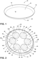
FIG. 1 is a top perspective view of a crisp plate; -
FIG. 2 is a bottom perspective view of the crisp plate ofFIG. 1 ; -
FIG. 3 is a cross-sectional view of the crisp plate ofFIG. 2 taken at line III; -
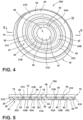
FIG. 4 is a bottom perspective view of another embodiment of the crisp plate ofFIG. 1 ; -
FIG. 5 is a cross-sectional view of the crisp plate ofFIG. 4 taken at line V; -
FIG. 6 is a front perspective view of a microwave oven having the crisp plate ofFIG. 1 disposed in a lower portion thereof; -
FIG. 7 is a fragmentary cross-sectional view of a microwave oven having the crisp plate ofFIG. 1 supported on a roller mechanism; -
FIG. 8 is a top perspective view of an induction hob; and -
FIG. 9 is a top perspective view of the induction hob ofFIG. 8 with the crisp plate ofFIG. 1 supported on a cooktop surface thereof. - For purposes of description herein the terms "upper," "lower," "right," "left," "rear," "front," "vertical," "horizontal," and derivatives thereof shall relate to the device as oriented in
FIG. 1 . However, it is to be understood that the device may assume various alternative orientations and step sequences, except where expressly specified to the contrary. It is also to be understood that the specific devices and processes illustrated in the attached drawings, and described in the following specification are simply exemplary embodiments of the inventive concepts defined in the appended claims. Hence, specific dimensions and other physical characteristics relating to the embodiments disclosed herein are not to be considered as limiting, unless the claims expressly state otherwise. - A crisp plate or browning plate usually comprises a microwave absorbing layer arranged in thermal contact with another layer having relatively good thermal conductivity. In particular, the antennas are preferably arranged, such that the magnetic field vector of microwaves fed into a cooking cavity of microwave oven is directed substantially along the microwave-absorbing layer in order to generate magnetic losses in the layer and thereby heat the crisp plate or browning plate. Typically, the microwave-absorbing layer corresponds to the underside (or the sole) of the crisp plate or browning plate, and the piece of food can be browned on the thermally conductive layer, i.e. at the upper side of the crisp or browning plate. Generally, the upper side of the crisp plate or browning plate may consist of an aluminum (or steel) plate which has small thermal mass and good thermal conductivity and possibly a non-stick coating. In the present specification, a
crisp plate 10 is provided, wherein microwave-absorbing materials and induction materials are positioned horizontally adjacent to one another in a patterned configuration, as opposed to a stacked or layered configuration known in the art. In this way, microwave-absorbing materials are positioned side-by-side with induction materials, as opposed to one on top of another in a traditional layered configuration, as further described below. Thus, in the present concept, the microwave-absorbing material and the induction material are in contact with a cooking surface of thecrisp plate 10, instead of just one material being in contact with the cooking surface in a layered configuration. - Referring now to
FIG. 1 , acrisp plate 10 is shown having acooking surface 12. Thecooking surface 12 is a substantially planar surface configured to support a food item for cooking. In the embodiment shown inFIG. 1 , arim 14 upwardly extends from thecooking surface 12 to define aninterior volume 16 of thecrisp plate 10. Thecrisp plate 10 further includes alower portion 20 disposed below thecooking surface 12. Anunderside 22 of thelower portion 20 of thecrisp plate 10 is positioned opposite thecooking surface 12, and is used to support thecrisp plate 10 in a substantially upright manner. Thecrisp plate 10 is contemplated to be comprised of a metal material, such as a non-ferrous metal material like aluminum for example, which is highly thermally conductive. More particularly, thecrisp plate 10 may include acasing 18 made of the highly thermally conductive metal material noted above, e.g. aluminum, wherein thecasing 18 surrounds side portions of thelower portion 20 and further includes thecooking surface 12 and therim 14. - Referring now to
FIG. 2 , theunderside 22 of thelower portion 20 of thecrisp plate 10 of the present concept is shown with a microwave-absorbingmaterial 30 disposed in thelower portion 20 of thecrisp plate 10. The microwave-absorbingmaterial 30 is contemplated to be positioned at least in discrete zones of thelower portion 20, such that the microwave-absorbingmaterial 30 is thermally coupled to thecooking surface 12 of thecrisp plate 10. In this way, the microwave-absorbingmaterial 30 heats thecooking surface 12 when the microwave-absorbingmaterial 30 is exposed to electromagnetic radiation and absorbs the same. The microwave-absorbingmaterial 30 may include a ferrite component and a rubber component to provide a rubber-embedded ferrite material. The rubber material may include an epoxy resin or a silicon dioxide component. In an embodiment wherein the microwave-absorbingmaterial 30 includes a rubber-embedded ferrite material, such a material composition may include a proportion of about 75% of a ferrite component and about 25% of a silicon dioxide component. The rubber component is non-reactive to microwave energy. The ferrite component is highly reactive to microwave energy and absorbs microwave energy when exposed thereto. The term "ferrites" refers to magnetic oxides containing iron as a major component thereof. The ferrite component has a Curie point at which absorption of microwaves in the material ceases. The characteristics for absorption of the microwaves in the ferrite component may be varied by altering the thickness of the microwave-absorbingmaterial 30 and/or the composition of the microwave-absorbingmaterial 30. Having the microwave-absorbingmaterial 30, thecrisp plate 10 of the present concept is suitable for use in a microwave oven where microwaves are generated and absorbed by the microwave-absorbingmaterial 30 to then rapidly heat thecooking surface 12 of thecrisp plate 10 to provide a browning feature for food cooked on thecrisp plate 10. Thus, the microwave-absorbingmaterial 30 is configured to increase in temperature upon absorption of electromagnetic radiation provided by a microwave oven. Use of thecrisp plate 10 in a microwave oven, is further described below with reference toFIGS. 6-7 . - With further reference to
FIG. 2 , thecrisp plate 10 of the present concept further includes aninduction material 42 disposed in discrete zones of thelower portion 20 of thecrisp plate 10. Theinduction material 42 is contemplated to be made from an electrically conductive material. The electrically conductive material comprising theinduction material 42 is preferably a ferromagnetic material, such as 400 series stainless steel, iron or the like. Theinduction material 42 is configured to be inductively heated via an electromagnetic field generated by an inductive coil of an induction cooktop when theinduction material 42 is exposed to the electromagnetic field. Thus, an electrical current is induced in theinduction material 42 by an electromagnetic field when thecrisp plate 10 is placed on an active induction cooktop. Like the microwave-absorbingmaterial 30 noted above, theinduction material 42 is positioned within thelower portion 20 of thecrisp plate 10, such that the induction material is thermally coupled to thecooking surface 12 of thecrisp plate 10. As such, theinduction material 42 heats thecooking surface 12 when the electrical current is induced in theinduction material 42. Thus, thecrisp plate 10 of the present concept includes two different heating materials (the microwave-absorbingmaterial 30, and the induction material 42) that are discretely positioned within thelower portion 20 of thecrisp plate 10 and thermally coupled to thecooking surface 12 of thecrisp plate 10, thereby forming respective heating arrangements or patterns. This thermal coupling arrangement may include the microwave-absorbingmaterial 30 and theinduction material 42 being in direct contact with thecooking surface 12, or may include a configuration wherein the microwave-absorbingmaterial 30 and theinduction material 42 are positioned adjacent to thecooking surface 12. - The
induction material 42 is contemplated to be at least partially electrically resistive, such that an induced electrical current within theinduction material 42 creates heat within theinduction material 42 when theinduction material 42 is exposed to an electromagnetic field. This heat from the induced electrical current in theinduction material 42 is transferred into theinterior volume 16 of thecrisp plate 10, such that cooking operations can be accomplished within theinterior volume 16 of thecrisp plate 10, specifically at thecooking surface 12, to which theinduction material 42 is thermally coupled. - In the various embodiments, it is contemplated that the
induction material 42 can be made of various materials that are both ferromagnetic and electrically conductive, such that theinduction material 42 is electromagnetically contoured. Such materials contemplated for use as theinduction material 42 of the present concept may include, but are not limited to, iron, nickel, cobalt, alloys thereof, metal oxide hybrids, and other various materials that are both ferromagnetic and electrically conductive. The ferromagnetic properties of theinduction material 42 provide thecrisp plate 10 with the properties necessary to operate in conjunction with an induction cooking appliance. Use of thecrisp plate 10 with an induction cooking appliance is further described below with reference toFIGS. 8-9 . - It is further contemplated that, in various embodiments, the
induction material 42 can be made up of more than one material, wherein one material is ferromagnetic and another material is electrically conductive. In such an embodiment, the two materials would be combined, such that the necessary ferromagnetic and electrically conductive properties can be included within theinduction material 42 when exposed to a magnetic field of an induction cooking appliance. The combination of such materials can be accomplished by creating an alloy of various metals, or by forming a structure where the ferromagnetic material and the electrically conductive material are mechanically combined by one of various operations that may include, but are not limited to, layering, weaving, using alternating bands of dissimilar metals, and other various combining operations that are sufficient to distribute the ferromagnetic and electrically conductive properties evenly across the specific locations of theunderside 22 of thecrisp plate 10 where theinduction material 42 is positioned. - As further shown in
FIG. 2 , the microwave-absorbingmaterial 30 defines abackground 32 having anouter surface 33. A plurality ofdiscrete deposits 40 ofinduction material 42 is disposed within the microwave-absorbingmaterial 30. The plurality ofdiscrete deposits 40 ofinduction material 42 are shown inFIG. 2 ascolumns 42A-42F ofinduction material 42 disposed along theunderside 22 of thecrisp plate 10. As specifically shown inFIG. 2 , thecolumns 42A-42F ofinduction material 42 are positioned in aring pattern 44 to evenly distribute theinduction material 42 along theunderside 22 of thecrisp plate 10. In the embodiment shown inFIG. 2 , the microwave-absorbingmaterial 30 is configured around aperimeter 24 of theunderside 22 of thecrisp plate 10. The microwave-absorbingmaterial 30 is also positioned within acenter 46 of thering pattern 44 and between eachcolumn 42A-42F of theinduction material 42, such that the microwave-absorbingmaterial 30 is also evenly distributed along theunderside 22 of thecrisp plate 10. It is contemplated that thecolumns 42A-42F of theinduction material 42 and the microwave-absorbingmaterial 30 surrounding thecolumns 42A-42F of theinduction material 42 may be exposed features on theunderside 22 of thecrisp plate 10, as shown inFIG. 2 . As further shown inFIG. 2 , eachcolumn 42A-42F of theinduction material 42 includes anouter surface 45. Theouter surfaces 45 of eachcolumn 42A-42F of theinduction material 42 may extend beyond theouter surface 33 defined by the microwave-absorbingmaterial 30. In this way, thecolumns 42A-42F of theinduction material 42 act as a stand-off feature to defineair gaps 49 therebetween. Theair gaps 49 facilitate the ability of microwaves to reach the microwave-absorbingmaterial 30 during a microwave cooking technique, as further described below. - As noted above, the
lower portion 20 of thecrisp plate 10 is positioned below thecooking surface 12. Thelower portion 20 may be provided in the form of a downwardly opening cavity. The microwave-absorbingmaterial 30 and theinduction material 42 are contemplated to be disposed in a side-by-side or horizontally adjacent configuration within thelower portion 20 of thecrisp plate 10. Thus, the microwave-absorbingmaterial 30 and theinduction material 42 are not layered on top of one another, but rather positioned horizontally adjacent to one another below thecooking surface 12. In this way, both the microwave-absorbingmaterial 30 and theinduction material 42 are positioned within thermal proximity to thecooking surface 12. The position of the microwave-absorbingmaterial 30 and theinduction material 42 relative to thecooking surface 12 can be described as the microwave-absorbingmaterial 30 and theinduction material 42 being in thermal proximity to thecooking surface 12, in thermal communication with thecooking surface 12, directly coupled with thecooking surface 12, or thermally coupled to thecooking surface 12. The configuration of the microwave-absorbingmaterial 30 and theinduction material 42 to thecooking surface 12 provides for a heating of thecooking surface 12 via the microwave-absorbingmaterial 30 or theinduction material 42 when thecrisp plate 10 is exposed to electromagnetic radiation in a microwave, or exposed to an electromagnetic field, respectively. As such, the microwave-absorbingmaterial 30 defines a first material disposed within thelower portion 20 of thecrisp plate 10 that is in thermal proximity to thecooking surface 12. This first material (i.e. the microwave-absorbing material 30) increases in temperature upon absorption of electromagnetic radiation, as exposed thereto in a microwave oven. Similarly, theinduction material 42 defines a second material disposed within thelower portion 20 of thecrisp plate 10 that is in thermal proximity to thecooking surface 12. An electrical current is induced in this second material (i.e. the induction material 42) upon exposure to an electromagnetic field generated by an induction cooktop. - As shown in the various embodiments of the
crisp plate 10 provided herein, theinduction material 42 is disposed in discrete portions of thelower portion 20. That is to say, theinduction material 42 is not intermixed or vertically layered within thelower portion 20 of thecrisp plate 10, but rather, positioned in discrete portions of thelower portion 20 of thecrisp plate 10. WhileFIG. 2 shows the microwave-absorbingmaterial 30 as thebackground 32 to theinduction material 42, is contemplated that the portions of thelower portion 20 filled with the microwave-absorbingmaterial 30 inFIG. 2 could be filled with theinduction material 42, wherein the microwave-absorbingmaterial 30 would be positioned in discrete deposits within thelower portion 20. The overall patterned configuration illustrated inFIG. 2 is engineered to provide sufficient coverage of both the microwave-absorbingmaterial 30 and theinduction material 42 to thecooking surface 12 of thecrisp plate 10, such that thecrisp plate 10 can be rapidly heated in a microwave oven, or on an induction cooktop. - Referring now to
FIG. 3 , the cross-sectional view of thecrisp plate 10 ofFIG. 3 shows discrete portions of thelower portion 20 having the microwave-absorbingmaterial 30 and theinduction material 42 positioned in a side-by-side configuration or a horizontally adjacent configuration, wherein both the microwave-absorbingmaterial 30 and theinduction material 42 are disposed directly below thecooking surface 12 within thelower portion 20, such that the microwave-absorbingmaterial 30 and theinduction material 42 are both in thermal communication with thecooking surface 12 of thecrisp plate 10 in an evenly dispersedpattern 44. Typically, a crisp plate is positioned within a microwave oven on a glass turntable or even directly supported on a bottom wall of a microwave oven cavity. An important feature to allow microwaves to reach the microwave-absorbing material is to keep an air gap between a support surface and the underside of the crisp plate. This is usually achieved by supporting features, such as feet or spacers, which are provided directly on the microwave-absorbing material. According to the present concept, this feature is provided by managing the thickness of theferromagnetic induction material 42 in such a way that theinduction material 42 is in contact with an induction cooktop, when used thereon, and to provide the spacing necessary to allow microwaves to reach the microwave-absorbingmaterial 30 when used in a microwave oven. As shown inFIG. 3 , theouter surfaces 45 of thecolumns 42A-42F of theinduction material 42 define asupport surface 48 that extends beyond theouter surface 33 defined by the microwave-absorbingmaterial 30. In this way, thesupport surface 48 provides theair gaps 49 needed to provide microwaves access to the microwave-absorbingmaterial 30 in a microwave oven, and to ensure direct contact of theinduction material 42, at thesupport surface 48, to an induction cooktop to facilitate maximum matching and efficiency when used with an induction cooktop. - As further shown in the embodiment of
FIG. 3 , theouter surface 33 of the microwave-absorbingmaterial 30 is disposed in a first plane P1, while thesupport surface 48 made up of thecolumns 42A-42F of theinduction material 42 that extend beyond theouter surface 33 of the microwave-absorbingmaterial 30 are positioned in a second plane P2. The first plane and the second plane P2 are spaced apart by a distance D1, which defines a length of theair gaps 49 provided by the configuration shown inFIG. 3 . Thus, as shown inFIG. 3 , the microwave-absorbingmaterial 30 is configured within thelower portion 20 to define theouter surface 33 thereof that is positioned within the first plane P1. The discrete portions of theinduction material 42 each include anouter surface 45 positioned within the second plane P2 that is outwardly spaced-apart from the first plane P1 by a distance D1. Said differently, the microwave-absorbingmaterial 30 defines a first material configured within thelower portion 20 of thecrisp plate 10 to define anouter surface 33 of the first material. Each column of thecolumns 42A-42F of the plurality ofcolumns 40 includes anouter surface 45 defining asupport surface 48 of thecrisp plate 10 that is comprised of a second material (i.e. the induction material 42). This is due to the configuration shown inFIGS. 2 and3 , wherein the distal ends (identified at or near the outer surfaces 45) of the of thecolumns 42A-42F extend outwardly beyond theouter surface 33 of the first material (i.e. the microwave-absorbing material 30). - Referring now to
FIG. 4 , the microwave-absorbingmaterial 30 and theinduction material 42 are shown disposed in an alternatingring pattern 41 along thelower portion 20 of acrisp plate 10A. As specifically shown inFIG. 4 , thecrisp plate 10A includes a centrally-disposedcircle 31A of microwave-absorbingmaterial 30 positioned within thelower portion 20 of thecrisp plate 10A. Positioned around anouter perimeter 47 of the centrally-disposedcircle 31A is aring 43A comprised of theinduction material 42. As further shown inFIG. 4 , the alternatingring pattern 41 of thecrisp plate 10A includes a plurality ofrings induction material 42 configured in an alternating ring configuration with a plurality ofrings material 30. It is contemplated that any number of alternating rings may be provided in the alternatingring pattern 41 of thecrisp plate 10A as necessary to provide an even distribution of the microwave-absorbingmaterial 30 and theinduction material 42 relative to thecooking surface 12 of thecrisp plate 10A. It is further contemplated that the rings of the alternatingring pattern 41 of thecrisp plate 10A may be configured in an opposite configuration wherein thecenter 46 of thelower portion 20 may be provided with theinduction material 42 that is surrounded by the microwave-absorbingmaterial 30, from which the alternatingring pattern 41 radiates outwardly therefrom alternating materials towards theperimeter 24 of thelower portion 20. The alternating ring pattern is advantageous in that it allows to achieve a more uniform heating pattern of the cooking surface whatever the heating source is. Much like thecolumns 42A-42F of theinduction material 42 discussed above with reference tocrisp plate 10, outer surfaces of therings induction material 42 ofcrisp plate 10A may extend beyond outer surfaces of therings material 30 to define a support surface and air gap configuration. - As shown in
FIG. 4 , thelower portion 20 of thecrisp plate 10A includes a first zone (ring 43A of the induction material 42) surrounding a second zone (centrally-disposedcircle 31A of the microwave-absorbing material 30). Similarly, it can be said that thelower portion 20 of thecrisp plate 10 ofFIG. 2 includes a first zone (thebackground 32 of the microwave-absorbing material 30) surrounding a second zone (any one of thecolumns 42A-42F of the induction material 42). Thus, inFIG. 2 , theinduction material 42 is positioned in a plurality ofcolumns 40 within thelower portion 20, wherein the microwave-absorbingmaterial 30 surrounds eachcolumn 42A-42F of the plurality ofcolumns 40 ofinduction material 42 within thelower portion 20. - Referring now to
FIG. 5 , the cross-sectional view of thecrisp plate 10A ofFIG. 4 shows discrete portions of thelower portion 20 having the microwave-absorbingmaterial 30 and theinduction material 42 positioned in an alternating side-by-side configuration or a horizontally adjacent configuration, wherein both the microwave-absorbingmaterial 30 and theinduction material 42 are disposed directly below thecooking surface 12 within thelower portion 20, such that the microwave-absorbingmaterial 30 and theinduction material 42 are both in thermal communication with thecooking surface 12 of thecrisp plate 10 in an evenly dispersedpattern 41. - Referring now to
FIG. 6 , amicrowave oven 50 is shown, in which a door for closing acooking cavity 52 of themicrowave oven 50 has been omitted. Thecooking cavity 52 is defined by sidewalls 54 and 56, atop wall 58, abottom wall 60, and arear wall 62. Thecrisp plate 10 is shown positioned on thebottom wall 60 of themicrowave oven 50. Disposed along theright sidewall 56, anopening 64 is configured to supply microwaves into thecooking cavity 52. With thecrisp plate 10 directly supported on thebottom wall 60 of themicrowave oven 50, the standoff feature provided by the air gaps 49 (FIGS. 2 and3 ) of thecrisp plate 10 will allow for the microwaves of themicrowave oven 50 to reach the microwave-absorbingmaterial 30. Specifically, with reference toFIG. 7 ,microwaves 66 are directed into thecooking cavity 52 of themicrowave oven 50 by awaveguide device 70 as generated from amicrowave source 68. As shown inFIG. 7 , theopening 64 and thewaveguide device 70 are arranged to supplymicrowaves 66 to thecooking cavity 52 for cooking a food item, and are specifically configured to directmicrowaves 66 to thecrisp plate 10. In this way, the microwave-absorbingmaterial 30 can absorb the electromagnetic radiation provided by themicrowaves 66 to then heat the microwave-absorbingmaterial 30, which then heats thecooking surface 12 of thecrisp plate 10. It is contemplated that thecrisp plate 10 may be supported on thebottom wall 60 of themicrowave oven 50 by aglass plate 71 that is further supported by arotation mechanism 72. Therotation mechanism 72 is configured to rotate theglass plate 71 and thecrisp plate 10 within thecooking cavity 52 of themicrowave oven 50 during a microwave cooking sequence. - Referring now to
FIGS. 8 and 9 , aninduction cooktop 80 is shown. As noted above, thecrisp plate 10 is configured to be used with aninduction cooktop 80, wherein theinduction cooktop 80 creates a magnetic field that is configured to induce an electrical current within theinduction material 42 of thecrisp plate 10. Theinduction cooktop 80 may be referred to herein as an induction hob or an induction cooking appliance. Theinduction cooktop 80 is shown having auser interface 82 disposed on a front portion thereof. Theuser interface 82 is used to control heating elements disposed within ahousing 84 for heating acooktop surface 86. Thecooktop surface 86 is an upper planar surface having a generally centrally-disposedheating zone 88 with a plurality ofinductive coils 90 disposed thereunder. The inductive coils 90 are configured to inductively heat theinduction material 42 of thecrisp plate 10 via an electromagnetic field generated by theinductive coils 90. With specific reference toFIG. 9 , thecrisp plate 10 of the present concept is shown abuttingly supported on thecooktop surface 86 in an upright position over the heating zone 88 (FIG. 8 ) of theinduction cooktop 80. Thecolumns 42A-42F of the plurality ofcolumns 40 ofinduction material 42 are shown positioned below thecooking surface 12 of thecrisp plate 10, such that theinduction material 42 of thecrisp plate 10 is in proximity to the electromagnetic field generated by theinduction cooktop 80 to heat theinduction material 42, which then heats thecooking surface 12 of thecrisp plate 10 to which theinduction material 42 is in thermal proximity thereof. - As noted above, the microwave-absorbing
material 30 and theinduction material 42 are adjacent to thecooking surface 12 of thecrisp plate 10, as disposed within discrete portions of thelower portion 20 of thecrisp plate 10. In this way, the microwave-absorbingmaterial 30 and theinduction material 42 are separate and distinct from one another and are not intermixed with one another nor layered vertically above or below one another. - In at least one aspect, a cooking vessel includes a cooking surface with a lower portion positioned below the cooking surface. A microwave-absorbing material is disposed within the lower portion. An induction material is disposed within the lower portion. The induction material is disposed in discrete portions of the lower portion.
- According to another aspect of the present disclosure, a cooking vessel includes a cooking surface and a lower portion positioned below the cooking surface. The lower portion includes discrete portions made of a magnetic field-absorbing material and discrete portions made of a ferromagnetic material, wherein the discrete portions made of a magnetic field-absorbing material are positioned side-by-side with the discrete portions made of a ferromagnetic material.
- According to another aspect of the present disclosure, the microwave-absorbing material is configured within the lower portion to define an outer surface positioned within a first plane, and the discrete portions of the induction material each include an outer surface positioned within a second plane that is outwardly spaced-apart from the first plane.
- According to another aspect of the present disclosure, the cooking surface is comprised of a metal material.
- According to another aspect of the present disclosure, the microwave-absorbing material includes a ferrite component.
- According to another aspect of the present disclosure, the microwave-absorbing material includes a silicon dioxide component.
- According to another aspect of the present disclosure, the microwave-absorbing material includes about 75% of the ferrite component and about 25% of the silicon dioxide component.
- According to another aspect of the present disclosure, the cooking surface is comprised of a non-ferrous metal material.
- According to another aspect of the present disclosure, the cooking surface is comprised of aluminum.
- According to another aspect of the present disclosure, the induction material is a ferromagnetic material.
- According to another aspect of the present disclosure, the induction material is configured to be inductively heated upon exposure to an electromagnetic field.
- According to another aspect of the present disclosure, the microwave-absorbing material includes a rubber-embedded ferrite material configured to increase in temperature upon absorption of electromagnetic radiation.
- In at least another aspect, a cooking vessel is configured for use with a microwave oven or with an induction cooktop. The cooking vessel includes a plate having a cooking surface. An induction material is formed of an electrically conductive material, such that an electrical current is induced in the induction material by an electromagnetic field when the plate is placed on an induction cooktop. The induction material is thermally coupled to the cooking surface of the plate. The induction material heats the cooking surface when the electrical current is induced in the induction material. A microwave-absorbing material includes a rubber-embedded ferrite material configured to increase in temperature upon absorption of electromagnetic radiation. The microwave-absorbing material is thermally coupled to the cooking surface of the plate. The microwave-absorbing material heats the cooking surface when exposed to electromagnetic radiation.
- According to another aspect of the present disclosure, the induction material is a ferromagnetic material.
- According to another aspect of the present disclosure, the microwave-absorbing material includes about 75% of a ferrite component and about 25% of a silicon dioxide component.
- According to another aspect of the present disclosure, the induction material and the microwave-absorbing material are positioned in a horizontally adjacent configuration below the cooking surface.
- In at least another aspect, a cooking vessel includes a cooking surface and a lower portion positioned below the cooking surface. A first material is disposed within the lower portion and is in thermal proximity to the cooking surface. The first material increases in temperature upon absorption of electromagnetic radiation. A second material is disposed within the lower portion and is in thermal proximity to the cooking surface. An electrical current is induced in the second material upon exposure to an electromagnetic field.
- According to another aspect of the present disclosure, the lower portion includes a first zone surrounding a second zone. The first material is positioned within the first zone, and the second material is positioned within the second zone.
- According to another aspect of the present disclosure, the second material is positioned in a plurality of columns within the lower portion, and the first material surrounds each column of the plurality of columns within the lower portion.
- According to another aspect of the present disclosure, the first material is configured within the lower portion to define an outer surface of the first material, and each column of the plurality of columns includes an outer surface defining a support surface of the cooking vessel, and the support surface of the cooking vessel extends outwardly from the outer surface of the first material.
- According to another aspect of the present disclosure, the first material is positioned in a centrally-disposed circle within the lower portion, and the second material surrounds an outer perimeter of the circle in a ring formation.
- According to another aspect of the present disclosure, the first and second materials are disposed in an alternating ring pattern within the lower portion.
- According to another aspect of the present disclosure, the first and second materials are disposed in a horizontally adjacent configuration within the lower portion.
- In at least another aspect, a cooking vessel includes a cooking surface and a lower portion positioned below the cooking surface. A first material is disposed within the lower portion and is in thermal proximity to the cooking surface. The first material increases in temperature upon absorption of electromagnetic radiation. A second material is disposed within the lower portion and is in thermal proximity to the cooking surface. An electrical current is induced in the second material upon exposure of the second material to an electromagnetic field.
- According to another aspect of the present disclosure, the lower portion includes a first zone surrounding a second zone. The first material is positioned within the first zone and the second material is positioned within the second zone.
- According to another aspect of the present disclosure, the second material is positioned in a plurality of columns within the lower portion, and the first material surrounds each column of the plurality of columns within the lower portion.
- According to another aspect of the present disclosure, the first material is configured within the lower portion to define an outer surface of the first material. Each column of the plurality of columns includes an outer surface defining a support surface of the cooking vessel. The support surface of the cooking vessel extends outwardly from the outer surface of the first material.
- According to another aspect of the present disclosure, the first material and the second material are disposed in an alternating ring pattern within the lower portion.
- According to another aspect of the present disclosure, the first material and the second material are disposed in a horizontally adjacent configuration within the lower portion.
- According to another aspect of the present disclosure, the first material includes a ferrite component.
- According to another aspect of the present disclosure, the first material includes a silicon dioxide component.
- According to another aspect of the present disclosure, the first material includes about % of the ferrite component and about % of the silicon dioxide component.
- According to another aspect of the present disclosure, the cooking surface is comprised of a non-ferrous metal material.
- According to another aspect of the present disclosure, the cooking surface is comprised of aluminum.
- According to another aspect of the present disclosure, the second material is a ferromagnetic material.
- According to another aspect of the present disclosure, the first material includes about % of a ferrite component and about % of a silicon dioxide component.
- According to another aspect of the present disclosure, the first material is configured within the lower portion to define an outer surface positioned within a first plane. The second material includes an outer surface positioned within a second plane that is outwardly spaced-apart from the first plane.
Claims (14)
- A cooking vessel (10), comprising:a cooking surface (12);a lower portion (20) positioned below the cooking surface (12);a first material (30) disposed within the lower portion (20) and in thermal proximity to the cooking surface (12), wherein the first material (30) increases in temperature upon absorption of electromagnetic radiation; anda second material (42) disposed within the lower portion (20) and in thermal proximity to the cooking surface (12), wherein an electrical current is induced in the second material (42) upon exposure to an electromagnetic field.
- The cooking vessel (10) of claim 1, wherein the lower portion (20) includes a first zone (43A) surrounding a second zone (31A), wherein the first material (30) is positioned within the first zone (43A), and further wherein the second material (42) is positioned within the second zone (31A).
- The cooking vessel (10) of claim 1, wherein the second material (42) is positioned in a plurality of columns (40) within the lower portion (20), and further wherein the first material (30) surrounds each column (42A-42F) of the plurality of columns (40) within the lower portion (20).
- The cooking vessel (10) of claim 3, wherein the first material (30) is configured within the lower portion (20) to define an outer surface (33) of the first material (30), and further wherein each column (42A-42F) of the plurality of columns (40) includes an outer surface (45) defining a support surface (48) of the cooking vessel (10), and further wherein the support surface (48) of the cooking vessel (10) extends outwardly from the outer surface (33) of the first material (30).
- The cooking vessel (10) of claim 1, wherein the first material (30) and the second material (42) are disposed in an alternating ring pattern (41) within the lower portion (20).
- The cooking vessel (10) of claim 1, wherein the first material (30) and the second material (42) are disposed in a horizontally adjacent configuration within the lower portion (20).
- The cooking vessel (10) of any one of claims 1-6, wherein the first material (30) includes a ferrite component.
- The cooking vessel (10) of claim 7, wherein the first material (30) includes a silicon dioxide component.
- The cooking vessel (10) of claim 8, wherein the first material (30) includes about 75% of the ferrite component and about 25% of the silicon dioxide component.
- The cooking vessel (10) of any one of claims 1-9, wherein the cooking surface (12) is comprised of a non-ferrous metal material.
- The cooking vessel (10) of claim 10, wherein the cooking surface (12) is comprised of aluminum.
- The cooking vessel (10) of claim 1, wherein the second material (42) is a ferromagnetic material.
- The cooking vessel (10) of claim 12, wherein the first material (30) includes about 75% of a ferrite component and about 25% of a silicon dioxide component.
- The cooking vessel (10) of claim 13, wherein the first material (30) is configured within the lower portion (20) to define an outer surface (33) positioned within a first plane (P1), and further wherein the second material (42) includes an outer surface (45) positioned within a second plane (P2) that is outwardly spaced-apart from the first plane (P1).
Applications Claiming Priority (1)
| Application Number | Priority Date | Filing Date | Title |
|---|---|---|---|
| US17/685,838 US20230276981A1 (en) | 2022-03-03 | 2022-03-03 | Cooking vessel |
Publications (1)
| Publication Number | Publication Date |
|---|---|
| EP4238459A1 true EP4238459A1 (en) | 2023-09-06 |
Family
ID=85462237
Family Applications (1)
| Application Number | Title | Priority Date | Filing Date |
|---|---|---|---|
| EP23160011.5A Pending EP4238459A1 (en) | 2022-03-03 | 2023-03-03 | Cooking vessel |
Country Status (2)
| Country | Link |
|---|---|
| US (1) | US20230276981A1 (en) |
| EP (1) | EP4238459A1 (en) |
Citations (3)
| Publication number | Priority date | Publication date | Assignee | Title |
|---|---|---|---|---|
| US6077454A (en) * | 1994-05-25 | 2000-06-20 | Ceramic Powders, Inc. | Ferrite compositions for use in a microwave oven |
| US7906748B2 (en) * | 2004-11-03 | 2011-03-15 | Mamoru Imura | Induction heatable cookware and serving ware, method of making induction heatable items, and coating for making induction heatable items |
| EP3025625A1 (en) * | 2014-11-28 | 2016-06-01 | Nolato Polymer AB | Method for producing a pan and a pan for use in a microwave-oven |
Family Cites Families (4)
| Publication number | Priority date | Publication date | Assignee | Title |
|---|---|---|---|---|
| CN201370439Y (en) * | 2009-01-08 | 2009-12-30 | 周赛方 | Aluminum alloy die-casting pan |
| PL2393339T3 (en) * | 2010-06-04 | 2017-03-31 | Whirlpool Corporation | Versatile microwave heating apparatus |
| CN102048449B (en) * | 2010-06-21 | 2012-03-28 | 王骥 | Multifunctional boiler |
| PL2901900T3 (en) * | 2014-01-30 | 2016-09-30 | Vessel for cooking food for induction or conventional surfaces |
-
2022
- 2022-03-03 US US17/685,838 patent/US20230276981A1/en active Pending
-
2023
- 2023-03-03 EP EP23160011.5A patent/EP4238459A1/en active Pending
Patent Citations (3)
| Publication number | Priority date | Publication date | Assignee | Title |
|---|---|---|---|---|
| US6077454A (en) * | 1994-05-25 | 2000-06-20 | Ceramic Powders, Inc. | Ferrite compositions for use in a microwave oven |
| US7906748B2 (en) * | 2004-11-03 | 2011-03-15 | Mamoru Imura | Induction heatable cookware and serving ware, method of making induction heatable items, and coating for making induction heatable items |
| EP3025625A1 (en) * | 2014-11-28 | 2016-06-01 | Nolato Polymer AB | Method for producing a pan and a pan for use in a microwave-oven |
Also Published As
| Publication number | Publication date |
|---|---|
| US20230276981A1 (en) | 2023-09-07 |
Similar Documents
| Publication | Publication Date | Title |
|---|---|---|
| EP2472185B1 (en) | Heating system | |
| US3845266A (en) | Microwave cooking utensil | |
| US3790735A (en) | Inductive heated bake oven | |
| AU2020432828B2 (en) | Cooking appliance | |
| JP5627726B2 (en) | Induction heating cooker | |
| US6288374B1 (en) | Coil and core structure for an induction cooktop | |
| EP3634087B1 (en) | Electromagnetic induction heating cooker | |
| CN107787604A (en) | For defrosting and/or the apparatus and method of cook food | |
| JP5322831B2 (en) | Induction heating cooker | |
| EP2393340B1 (en) | Microwave heating apparatus with rotatable antenna and method thereof | |
| US20230276981A1 (en) | Cooking vessel | |
| CA1306509C (en) | Microwave heating | |
| EP2452541B1 (en) | Induction oven | |
| KR101307594B1 (en) | Electric range having induction heater | |
| MX2014006914A (en) | Induction cooking apparatus. | |
| JPH08138864A (en) | Heating cooker | |
| US20240196489A1 (en) | Cooking appliance | |
| US11627644B2 (en) | Wireless induction heating cooker with improved heat conduction efficiency | |
| JPH04319288A (en) | Heating cooker | |
| KR101813279B1 (en) | Electric Hob | |
| JP3796856B2 (en) | High frequency heating device | |
| CN221202790U (en) | Electromagnetic heating device and electromagnetic cooking utensil | |
| JP2626034B2 (en) | Induction heating device | |
| KR102961247B1 (en) | Cooking appliance | |
| JP2532445B2 (en) | High frequency heating equipment |
Legal Events
| Date | Code | Title | Description |
|---|---|---|---|
| PUAI | Public reference made under article 153(3) epc to a published international application that has entered the european phase |
Free format text: ORIGINAL CODE: 0009012 |
|
| STAA | Information on the status of an ep patent application or granted ep patent |
Free format text: STATUS: THE APPLICATION HAS BEEN PUBLISHED |
|
| AK | Designated contracting states |
Kind code of ref document: A1 Designated state(s): AL AT BE BG CH CY CZ DE DK EE ES FI FR GB GR HR HU IE IS IT LI LT LU LV MC ME MK MT NL NO PL PT RO RS SE SI SK SM TR |
|
| STAA | Information on the status of an ep patent application or granted ep patent |
Free format text: STATUS: REQUEST FOR EXAMINATION WAS MADE |
|
| 17P | Request for examination filed |
Effective date: 20240305 |
|
| RBV | Designated contracting states (corrected) |
Designated state(s): AL AT BE BG CH CY CZ DE DK EE ES FI FR GB GR HR HU IE IS IT LI LT LU LV MC ME MK MT NL NO PL PT RO RS SE SI SK SM TR |