EP4238434B1 - Aerosol generating device comprising leakage preventing means and associated aerosol generating assembly - Google Patents
Aerosol generating device comprising leakage preventing means and associated aerosol generating assembly Download PDFInfo
- Publication number
- EP4238434B1 EP4238434B1 EP22159733.9A EP22159733A EP4238434B1 EP 4238434 B1 EP4238434 B1 EP 4238434B1 EP 22159733 A EP22159733 A EP 22159733A EP 4238434 B1 EP4238434 B1 EP 4238434B1
- Authority
- EP
- European Patent Office
- Prior art keywords
- aerosol generating
- generating device
- mouthpiece
- heating chamber
- airflow
- Prior art date
- Legal status (The legal status is an assumption and is not a legal conclusion. Google has not performed a legal analysis and makes no representation as to the accuracy of the status listed.)
- Active
Links
Images


Classifications
-
- A—HUMAN NECESSITIES
- A24—TOBACCO; CIGARS; CIGARETTES; SIMULATED SMOKING DEVICES; SMOKERS' REQUISITES
- A24F—SMOKERS' REQUISITES; MATCH BOXES; SIMULATED SMOKING DEVICES
- A24F40/00—Electrically operated smoking devices; Component parts thereof; Manufacture thereof; Maintenance or testing thereof; Charging means specially adapted therefor
- A24F40/40—Constructional details, e.g. connection of cartridges and battery parts
- A24F40/48—Fluid transfer means, e.g. pumps
- A24F40/485—Valves; Apertures
-
- A—HUMAN NECESSITIES
- A24—TOBACCO; CIGARS; CIGARETTES; SIMULATED SMOKING DEVICES; SMOKERS' REQUISITES
- A24D—CIGARS; CIGARETTES; TOBACCO SMOKE FILTERS; MOUTHPIECES OF CIGARS OR CIGARETTES; MANUFACTURE OF TOBACCO SMOKE FILTERS OR MOUTHPIECES
- A24D1/00—Cigars; Cigarettes
- A24D1/20—Cigarettes specially adapted for simulated smoking devices
-
- A—HUMAN NECESSITIES
- A24—TOBACCO; CIGARS; CIGARETTES; SIMULATED SMOKING DEVICES; SMOKERS' REQUISITES
- A24F—SMOKERS' REQUISITES; MATCH BOXES; SIMULATED SMOKING DEVICES
- A24F40/00—Electrically operated smoking devices; Component parts thereof; Manufacture thereof; Maintenance or testing thereof; Charging means specially adapted therefor
- A24F40/20—Devices using solid inhalable precursors
-
- A—HUMAN NECESSITIES
- A24—TOBACCO; CIGARS; CIGARETTES; SIMULATED SMOKING DEVICES; SMOKERS' REQUISITES
- A24F—SMOKERS' REQUISITES; MATCH BOXES; SIMULATED SMOKING DEVICES
- A24F40/00—Electrically operated smoking devices; Component parts thereof; Manufacture thereof; Maintenance or testing thereof; Charging means specially adapted therefor
- A24F40/40—Constructional details, e.g. connection of cartridges and battery parts
-
- A—HUMAN NECESSITIES
- A24—TOBACCO; CIGARS; CIGARETTES; SIMULATED SMOKING DEVICES; SMOKERS' REQUISITES
- A24F—SMOKERS' REQUISITES; MATCH BOXES; SIMULATED SMOKING DEVICES
- A24F7/00—Mouthpieces for pipes; Mouthpieces for cigar or cigarette holders
-
- F—MECHANICAL ENGINEERING; LIGHTING; HEATING; WEAPONS; BLASTING
- F16—ENGINEERING ELEMENTS AND UNITS; GENERAL MEASURES FOR PRODUCING AND MAINTAINING EFFECTIVE FUNCTIONING OF MACHINES OR INSTALLATIONS; THERMAL INSULATION IN GENERAL
- F16K—VALVES; TAPS; COCKS; ACTUATING-FLOATS; DEVICES FOR VENTING OR AERATING
- F16K15/00—Check valves
- F16K15/14—Check valves with flexible valve members
- F16K15/144—Check valves with flexible valve members the closure elements being fixed along all or a part of their periphery
- F16K15/147—Check valves with flexible valve members the closure elements being fixed along all or a part of their periphery the closure elements having specially formed slits or being of an elongated easily collapsible form
-
- H—ELECTRICITY
- H05—ELECTRIC TECHNIQUES NOT OTHERWISE PROVIDED FOR
- H05B—ELECTRIC HEATING; ELECTRIC LIGHT SOURCES NOT OTHERWISE PROVIDED FOR; CIRCUIT ARRANGEMENTS FOR ELECTRIC LIGHT SOURCES, IN GENERAL
- H05B3/00—Ohmic-resistance heating
- H05B3/02—Details
Definitions
- the present invention concerns an aerosol generating device comprising leakage preventing means.
- the aerosol generating device is configured to operate with a tobacco article, for example a flat-shaped tobacco article, which comprises for example a solid substrate able to form aerosol when being heated.
- a tobacco article for example a flat-shaped tobacco article, which comprises for example a solid substrate able to form aerosol when being heated.
- heat-not-burn devices is adapted to heat, rather than burn, the substrate by conduction, convection and/or radiation, to generate aerosol for inhalation.
- the present invention also concerns an aerosol generating assembly associated to such a device.
- reduced-risk or modified-risk devices also known as vaporisers
- vaporisers have grown rapidly in the past few years as an aid to assist habitual smokers wishing to quit smoking traditional tobacco products such as cigarettes, cigars, cigarillos, and rolling tobacco.
- Various devices and systems are available that heat or warm vaporizable substances as opposed to burning tobacco in conventional tobacco products.
- a commonly available reduced-risk or modified-risk device is the heated substrate aerosol generation device or heat-not-burn device.
- Devices of this type generate aerosol or vapour by heating an aerosol substrate that typically comprises moist leaf tobacco or other suitable vaporizable material to a temperature typically in the range 150°C to 350°C. Heating an aerosol substrate, but not combusting or burning it, releases aerosol that comprises the components sought by the user but not the toxic and carcinogenic byproducts of combustion and burning.
- the aerosol produced by heating the tobacco or other vaporizable material does not typically comprise the burnt or bitter taste resulting from combustion and burning that can be unpleasant for the user and so the substrate does not therefore require the sugars and other additives that are typically added to such materials to make the smoke and/or vapour more palatable for the user.
- Tobacco articles usable with such type of aerosol generating devices can take various forms. Some of them can present an elongated stick or any other suitable shape, like for example a flat shape. However, design of a tobacco article is often a trade-off between its aesthetics and efficiency in heating.
- vapour does not all go through the designed path including the mouthpiece portion of the article but instead can leak back up and out of the device, which reduces the overall vapour efficiency.
- Document US 2017/164657 A1 discloses an aerosol generating device where a flat tobacco element is received in a cavity which engages with a mouthpiece, the latter having an air inlet which is in fluid communication with the distal end of the flat tobacco element.
- One of the aims of the invention is to provide an aerosol generating device with increased vapour efficiency.
- the invention relates to an aerosol generating device configured to operate with a tobacco article comprising a substrate portion and a mouthpiece portion arranged successively along an article axis, the aerosol generating device comprising:
- the aerosol generating device further comprises leakage preventing means preventing flow leakage from the inner volume via the airflow inlet.
- the leakage preventing means comprise a valve arranged in the airflow inlet.
- the valve is configured to be opened while user puffs and closed in absence of user puffs.
- the valve forms thus a one-way fluidic valve which allows air entering into the device when the user takes a puff but prevents vapour from leaking back outwards.
- the valve opens directly to the inner volume.
- the airflow can be easily guided until the heating chamber. Additionally, in some cases, the entering airflow can be in contact with the tobacco article, for example with the mouthpiece portion of the tobacco article. This can cool down this mouthpiece portion and improve the user's perception of the inhaled flow.
- the valve is a duck bill valve.
- a duck bill valve is the preferred valve of choice as it can be made in a small size and is simple to implement. Other types like a conventional spring assisted check valve could also be used.
- an airflow channel is formed between the airflow inlet and the closed end of the heating chamber, the airflow channel being formed by an upstream portion extending from the airflow inlet through the inner volume and a downstream portion extending from the upstream portion until the closed end of the heating chamber.
- air from the outside of the device can be guided until the closed end of the heating chamber. Then, air passes inside the tobacco article first in the substrate portion and then, in the mouthpiece portion. After the mouthpiece portion, the flow is inhaled directly by the user.
- the downstream portion of the airflow channel extends outside or inside the heating chamber.
- the downstream portion of the airflow channel extends along a lateral wall of the heating chamber.
- the downstream portion When the downstream portion extends inside the heating chamber, it can extend from the opening until the closed end of the heating chamber. It can for example extend between a wall of the heating chamber and a wall of the tobacco article.
- the cross-section of the heating chamber may have at least one dimension which is greater than the corresponding dimension of the cross-section of the tobacco article.
- the downstream portion When the downstream portion extends outside the heating chamber, it can extend along for example at least one wall of the heating chamber, such as a lateral wall (called also narrow wall in the specification) and open at the closed end of the heating chamber. This improves the amount of air pulled through the substrate portion decreasing the importance of the fit of the consumable in the heating chamber. This also gives a more consistent pressure drop from one tobacco article to another.
- a lateral wall called also narrow wall in the specification
- the leakage preventing means comprise a bypass channel forming the upstream portion of the airflow channel, the bypass channel being fluidically isolated from the inner volume.
- the airflow inlet can be provided with or without a valve as explained above. Particularly, when no valve is provided, a backward flow is avoided only due to the bypass channel. When a valve is provided, a backward flow is avoided using both elements, valve and bypass channel.
- At least a portion of the bypass channel is delimited by a tube extending through the inner volume.
- bypass channel can be easily implemented in order to be isolated from the inner volume.
- the mouthpiece defines at least two airflow inlets on its internal surface in fluid communication with the closed end of the heating chamber; the aerosol generating device comprising leakage preventing means for each airflow inlet.
- the airflow inlets can be provided with the same leakage preventing means or with different leakage preventing means.
- at least one airflow inlet can be provided with a valve as explained above and at least one airflow inlet can be provided with a bypass channel as explained above.
- each airflow inlet is provided with a valve as explained above or with a bypass channel as explained above.
- the mouthpiece defines a through hole configured to be engaged with the mouthpiece portion of the tobacco article.
- the through hole can be adapted to tightly fit the tobacco article and thus to avoid or minimise flow leakage between the mouthpiece and the tobacco article. Additionally, the through hole can be adapted to maintain the tobacco article while for example its extraction from the device and/or insertion inside the device. Additionally, in some cases, the mouthpiece can also be adapted to maintain the tobacco article in the heating chamber with a distance from the heating walls. Thus, it is possible to ensure heating of the tobacco article by convection instead of conduction for example.
- said airflow inlets are arranged on different sides of the through hole.
- the tobacco article can be easily heated while being compact and easily handled by the user.
- the invention also relates to an aerosol generating assembly comprising a tobacco article and an aerosol generating device as defined above, configured to operate with the tobacco article.
- the term "aerosol generating device” or “device” may include a vaping device to deliver an aerosol to a user, including an aerosol for vaping, by means of a heater element explained in further detail below.
- the device may be portable.
- “Portable” may refer to the device being for use when held by a user.
- the device may be adapted to generate a variable amount of aerosol, e.g. by activating the heater element for a variable amount of time (as opposed to a metered dose of aerosol), which can be controlled by a trigger.
- the trigger may be user activated, such as a vaping button and/or inhalation sensor.
- the inhalation sensor may be sensitive to the strength of inhalation as well as the duration of inhalation to enable a variable amount of vapour to be provided (so as to mimic the effect of smoking a conventional combustible smoking article such as a cigarette, cigar or pipe, etc.).
- the device may include a temperature regulation control to drive the temperature of the heater and/or the heated aerosol generating substance (aerosol pre-cursor) to a specified target temperature and thereafter to maintain the temperature at the target temperature that enables efficient generation of aerosol.
- aerosol may include a suspension of vaporizable material as one or more of: solid particles; liquid droplets; gas. Said suspension may be in a gas including air. Aerosol herein may generally refer to/include a vapour. Aerosol may include one or more components of the vaporizable material.
- vaporizable material may refer to a smokable material which may for example comprise nicotine or tobacco and an aerosol former.
- tobacco may take the form of various materials such as shredded tobacco, granulated tobacco, tobacco leaf and/or reconstituted tobacco.
- Suitable aerosol formers include: a polyol such as sorbitol, glycerol, and glycols like propylene glycol or triethylene glycol; a non-polyol such as monohydric alcohols, acids such as lactic acid, glycerol derivatives, esters such as triacetin, triethylene glycol diacetate, triethyl citrate, glycerin or vegetable glycerin.
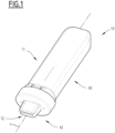
- the tobacco article 12 is a flat-shaped tobacco article presenting for example a flat-shaped cuboid extending along an article axis X and having external dimensions LxWxD.
- the length L of the article 12 according to the article axis X equals substantially to 33 mm while its width W and depth D are substantially equal respectively to 12 mm and 1,2 mm.
- the values L, W and D can be selected within a range of +/- 40%, for example.
- the tobacco article 12 comprises a substrate portion 15 and a mouthpiece portion 16 arranged along the article axis X.
- the substrate portion 15 may for example be slightly longer than the mouthpiece portion 16.
- the length L2 of the substrate portion 15 according to the article axis X may be substantially equal to 18 mm and the length L1 of the mouthpiece portion 16 according to the article axis X may be substantially equal to 15 mm.
- the substrate portion 15 defines an abutting end 18 of the article 12 and the mouthpiece portion 16 defines a mouth end 20 of the article 12.
- the substrate portion 15 and the mouthpiece portion 16 may be fixed one to the other by a wrapper 21 extending around the substrate axis X.
- the wrapper 21 forms the narrow and wide walls 13A, 13B, 14A, 14B of the tobacco article 12.
- the wrapper 21 is formed from a same wrapping sheet.
- the wrapper 21 is formed by separate wrapping sheets wrapping separately the portions 15, 16 and fixed one to the other by any other suitable mean.
- the wrapper 21 may, for example, comprise paper and/or non-woven fabric and/or aluminium foil.
- the wrapper 21 may be porous or air impermeable and forms a plurality of airflow channels extending inside the article 12 between the abutting end 18 and the mouth end 20.
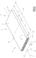
- the aerosol generating device 11 comprises a device body 40 extending along a device axis Y and a mouthpiece 42.
- the mouthpiece 42 and the device body 40 form two different pieces.
- the mouthpiece 42 is designed to be fixed on a fixing end of the device body 40.
- the central part 43 of the mouthpiece 42 defines a through hole 46 adapted to receive at least partially the tobacco article 12.
- the through hole 46 can be adapted to receive at least a part of the mouthpiece portion 16 of the tobacco article 12 as it is shown in Figure 3 .
- the through hole 46 can be adapted to fit tightly the mouthpiece portion 16 of the tobacco article 12 so as to avoid or minimise flow leakage between a wall delimiting the through hole 46 and an external surface of the tobacco article 12.
- the tobacco article 12 can be retained for example by friction in the through hole 46. In this case, it is possible for example to insert first the mouthpiece portion 16 of the tobacco article 12 inside the through hole 46 and when fix both elements on the fixing end of the device body 40.
- the heating chamber 50 can form a cup shape adapted to receive at least the substrate portion 15 of the tobacco article 12 and in some cases, at least a part of the mouthpiece portion 16.
- the heating chamber 50 may also form a cuboid shape extending along the device axis Y and comprising a pair of parallel narrow walls 53A, 53B (shown in Figures 4 and 6 ) extending along the device axis Y, a pair of parallel wide walls 54A, 54B extending also along the device axis Y and a bottom wall 58 adjacent to each of said walls and extending perpendicularly to the device axis Y.
- the bottom wall 58 forms thus a closed end of the chamber 50.
- the heating chamber 50 defines an opening 60 configured to receive the tobacco article 12 so as the corresponding wide walls 14A, 14B of the tobacco article 12 face the corresponding wide walls 54A, 54B of the heating chamber 50, the corresponding narrow walls 13A, 13B of the tobacco article 12 face the corresponding narrow walls 53A, 53B of the heating chamber 50 and the abutting end 18 of the tobacco article 12 abuts against the bottom wall 58 or at least a rib extending from this bottom wall 58. Alternatively, the abutting end 18 faces the bottom wall 58 without being in contact with it.
- the heating chamber 50 is thus configured to receive the tobacco article 12 so as the narrow wall 13A (respectfully 13B) of the tobacco article 12 faces the narrow wall 53B (respectfully 53A) of the heating chamber 50, and the wide wall 14A (respectfully 14B) of the tobacco article 12 faces the wide wall 54B (respectfully 54A) of the heating chamber 50.
- the facing wide walls 14A, 14B, 54A, 54B and the facing narrow walls 13A, 13B, 53A, 53B can be in contact one with the other or spaced one from the other.
- the heating chamber 50 further comprises one or several heating elements (not-shown) arranged to heat the substrate portion 15 of the tobacco article 12.
- the or each heating element can present for example a restive element arranged adjacent to at least one of the walls 53A, 53B, 54A, 54B of the heating chamber 50.
- a resistive heating element as for example a heating track or a polyimide film heater, is arranged adjacent to each wide wall 54A, 54B of the heating chamber 50, for example on an external surface of such a wall.
- the or each heating element presents any other suitable mean, as for example a heating blade penetrating the substrate portion 15 of the tobacco article 12.
- the or each heating element presents a magnetic element able to cause heating of a plurality of susceptors comprised in the substrate portion 15 by magnetic induction.
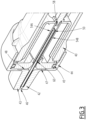
- an airflow channel extending from an airflow inlet 65 (shown in Figures 4 and 6 ) until the closed end of the heating chamber 50 is formed inside the aerosol generating device 11.
- air can enter the heating chamber 50 through the airflow channel and pass first to the substrate portion 15 and then through the mouthpiece portion 16 of the tobacco article 12 before being delivered to the user.
- the airflow inlet 65 is arranged in the mouthpiece 42, advantageously in the intermediate portion of the peripheral part 44 of this mouthpiece 42.
- the airflow inlet 65 can be formed by a through hole.
- the airflow channel is formed by an upstream portion extending from the airflow inlet 65 and a downstream portion extending from the upstream portion until the closed end of the heating chamber 50.
- the downstream portion may extend inside or outside the heating chamber 50.
- the downstream portion extends inside the heating chamber 50 from its opening 60 until the closed end.
- the downstream portion can be formed between a narrow wall 13A, 13B of the tobacco article 12 and the corresponding narrow wall 53A, 53B of the heating chamber 50.
- the downstream portion extends outside the heating chamber through for example a dedicated channel extending along a narrow wall 53A, 53B of the heating chamber 50. In this case, the downstream portion opens to the closed end of the heating chamber 50.
- the arrangement of the upstream portion depends on different embodiments of the invention explained in further detail below.
- airflow channels can be formed inside the aerosol generating device 11, each of these channels being similar to the channel described above.
- these channels can be arranged symmetrically in respect with the through hole 46 of the mouthpiece 42.
- two airflow channels are arranged symmetrically in respect with the through hole 46.
- the aerosol generating device 11 further comprises leakage preventing means 180, 280 preventing flow leakage from the inner volume 47.
- leakage preventing means 180, 280 depends on different embodiments of the invention explained in further detail below.
- the leakage preventing means 180 according to the first embodiment of the invention will now be explained in reference to Figure 4 .
- the leakage preventing means 180 comprise a valve arranged in the or each airflow inlet 65. Additionally, according to this embodiment, the or each airflow inlet 65 opens directly to the inner volume 47. Thus, in this case, the upstream portion of the corresponding airflow channel extends through this inner volume 47, for example without being delimited inside this volume.
- valve forming the leakage preventing means 180 is shown in Figure 5 .
- the valve is a duck bill valve configured to be opened while user puffs (configuration shown in the up part of the Figure) and closed in absence of user puffs (configuration shown in the down part of the Figure).
- the valve is configured to be opened upon an airflow occurring from the outside of the device 11 to the inside and closed otherwise.
- the leakage preventing means 280 according to the second embodiment of the invention will now be explained in reference to Figure 6 .
- the bypass channel 280 is delimited by a tube extending through the inner volume 47. According to other examples, the bypass channel 280 is at least partially formed by one or several surfaces delimiting the inner volume 47.
Landscapes
- Engineering & Computer Science (AREA)
- General Engineering & Computer Science (AREA)
- Mechanical Engineering (AREA)
- Manufacture Of Tobacco Products (AREA)
Priority Applications (6)
| Application Number | Priority Date | Filing Date | Title |
|---|---|---|---|
| EP22159733.9A EP4238434B1 (en) | 2022-03-02 | 2022-03-02 | Aerosol generating device comprising leakage preventing means and associated aerosol generating assembly |
| PL22159733.9T PL4238434T3 (pl) | 2022-03-02 | 2022-03-02 | Urządzenie wytwarzające aerozol zawierające środki zapobiegające wyciekowi i powiązany zespół wytwarzający aerozol |
| KR1020247025647A KR20240153314A (ko) | 2022-03-02 | 2023-03-01 | 누출 방지 수단을 포함하는 에어로졸 생성 디바이스 및 관련 에어로졸 생성 조립체 |
| US18/842,300 US20250185717A1 (en) | 2022-03-02 | 2023-03-01 | Aerosol Generating Device Comprising Leakage Preventing Means and Associated Aerosol Generating Assembly |
| JP2024549179A JP2025508769A (ja) | 2022-03-02 | 2023-03-01 | 漏れ防止手段を備えるエアロゾル発生装置及び関連するエアロゾル発生アセンブリ |
| PCT/EP2023/055200 WO2023166066A1 (en) | 2022-03-02 | 2023-03-01 | Aerosol generating device comprising leakage preventing means and associated aerosol generating assembly |
Applications Claiming Priority (1)
| Application Number | Priority Date | Filing Date | Title |
|---|---|---|---|
| EP22159733.9A EP4238434B1 (en) | 2022-03-02 | 2022-03-02 | Aerosol generating device comprising leakage preventing means and associated aerosol generating assembly |
Publications (3)
| Publication Number | Publication Date |
|---|---|
| EP4238434A1 EP4238434A1 (en) | 2023-09-06 |
| EP4238434B1 true EP4238434B1 (en) | 2024-09-11 |
| EP4238434C0 EP4238434C0 (en) | 2024-09-11 |
Family
ID=80625542
Family Applications (1)
| Application Number | Title | Priority Date | Filing Date |
|---|---|---|---|
| EP22159733.9A Active EP4238434B1 (en) | 2022-03-02 | 2022-03-02 | Aerosol generating device comprising leakage preventing means and associated aerosol generating assembly |
Country Status (6)
| Country | Link |
|---|---|
| US (1) | US20250185717A1 (cg-RX-API-DMAC10.html) |
| EP (1) | EP4238434B1 (cg-RX-API-DMAC10.html) |
| JP (1) | JP2025508769A (cg-RX-API-DMAC10.html) |
| KR (1) | KR20240153314A (cg-RX-API-DMAC10.html) |
| PL (1) | PL4238434T3 (cg-RX-API-DMAC10.html) |
| WO (1) | WO2023166066A1 (cg-RX-API-DMAC10.html) |
Families Citing this family (2)
| Publication number | Priority date | Publication date | Assignee | Title |
|---|---|---|---|---|
| JP2026516831A (ja) * | 2023-05-03 | 2026-05-26 | ジェイティー インターナショナル エスエイ | エアロゾル発生デバイスのための消耗品セット |
| WO2026003111A1 (en) * | 2024-06-25 | 2026-01-02 | Philip Morris Products S.A. | Aerosol-forming article and aerosol-forming device |
Family Cites Families (6)
| Publication number | Priority date | Publication date | Assignee | Title |
|---|---|---|---|---|
| EP3166430B2 (en) * | 2014-07-11 | 2025-03-26 | Philip Morris Products S.A. | Aerosol-forming cartridge comprising a tobacco-containing material |
| CN104223364B (zh) * | 2014-09-03 | 2017-01-18 | 深圳葆威道科技有限公司 | 烤烟电子烟 |
| US11229235B2 (en) * | 2017-07-14 | 2022-01-25 | Philip Morris Products S.A. | Aerosol-generating system with concealed ventilation airflow |
| WO2019162507A1 (en) * | 2018-02-26 | 2019-08-29 | Nerudia Limited | A substitute smoking consumable |
| CA3141947A1 (en) * | 2019-05-29 | 2020-12-03 | Jt International Sa | Cartridge for an aerosol generating device |
| CN115666280A (zh) * | 2020-03-12 | 2023-01-31 | 菲利普莫里斯生产公司 | 具有空气进入区的气溶胶生成系统 |
-
2022
- 2022-03-02 EP EP22159733.9A patent/EP4238434B1/en active Active
- 2022-03-02 PL PL22159733.9T patent/PL4238434T3/pl unknown
-
2023
- 2023-03-01 KR KR1020247025647A patent/KR20240153314A/ko active Pending
- 2023-03-01 US US18/842,300 patent/US20250185717A1/en active Pending
- 2023-03-01 JP JP2024549179A patent/JP2025508769A/ja active Pending
- 2023-03-01 WO PCT/EP2023/055200 patent/WO2023166066A1/en not_active Ceased
Also Published As
| Publication number | Publication date |
|---|---|
| JP2025508769A (ja) | 2025-04-10 |
| US20250185717A1 (en) | 2025-06-12 |
| WO2023166066A1 (en) | 2023-09-07 |
| EP4238434C0 (en) | 2024-09-11 |
| EP4238434A1 (en) | 2023-09-06 |
| PL4238434T3 (pl) | 2025-02-10 |
| KR20240153314A (ko) | 2024-10-22 |
Similar Documents
| Publication | Publication Date | Title |
|---|---|---|
| EP4337042B1 (en) | Aerosol generating device comprising a cup-shaped heating chamber defining an open end and a sealed end | |
| US20240415167A1 (en) | Flat-Shaped Tobacco Article Comprising a First Gap and a Second Gap, and Associated Aerosol Generating Device and Assembly | |
| US20240349802A1 (en) | Aerosol Generating Device Comprising a Flat-Shaped Heating Chamber and Associated Aerosol Generating Assembly | |
| US20240251854A1 (en) | Aerosol Generating Device Comprising Two Heating Elements | |
| US20250185717A1 (en) | Aerosol Generating Device Comprising Leakage Preventing Means and Associated Aerosol Generating Assembly | |
| US20240268452A1 (en) | Flat Tobacco Article Comprising at Least Two Layers and Aerosol Generating Device with Such an Article | |
| US20240423262A1 (en) | Flat-Shaped Tobacco Article Comprising a Gap, and Associated Aerosol Generating Device and Assembly | |
| EP4437874B1 (en) | Aerosol generating device comprising a heating chamber configured to receive at least partially an aerosol generating article | |
| US20250241372A1 (en) | Aerosol Generating Device Comprising a Heating Plate Comprising a Ceramic Part and a Metal Part and Associated Method for Controlling | |
| WO2024200643A1 (en) | Aerosol generating device comprising a gripping part and associated aerosol generating assembly | |
| EP4661704A1 (en) | Aerosol generating assembly comprising a cavity configured to receive an aerosol generating article | |
| WO2024200669A1 (en) | Aerosol generating device comprising a thermal break and associated aerosol generating assembly | |
| EP4704611A1 (en) | Consumable set for an aerosol generating device | |
| EP4701466A1 (en) | Tobacco article for a heat-not-burn aerosol generating device and associated aerosol generating system | |
| EP4701464A1 (en) | Tobacco article for a heat-not-burn aerosol generating device and associated aerosol generating system | |
| WO2024240644A1 (en) | Aerosol generating device configured to operate with a flat-shaped tobacco article and assembly comprising such aerosol generating device | |
| EP4651743A1 (en) | Aerosol generating device configured to operate with a flat-shaped tobacco article |
Legal Events
| Date | Code | Title | Description |
|---|---|---|---|
| PUAI | Public reference made under article 153(3) epc to a published international application that has entered the european phase |
Free format text: ORIGINAL CODE: 0009012 |
|
| STAA | Information on the status of an ep patent application or granted ep patent |
Free format text: STATUS: THE APPLICATION HAS BEEN PUBLISHED |
|
| AK | Designated contracting states |
Kind code of ref document: A1 Designated state(s): AL AT BE BG CH CY CZ DE DK EE ES FI FR GB GR HR HU IE IS IT LI LT LU LV MC MK MT NL NO PL PT RO RS SE SI SK SM TR |
|
| STAA | Information on the status of an ep patent application or granted ep patent |
Free format text: STATUS: REQUEST FOR EXAMINATION WAS MADE |
|
| 17P | Request for examination filed |
Effective date: 20240216 |
|
| RBV | Designated contracting states (corrected) |
Designated state(s): AL AT BE BG CH CY CZ DE DK EE ES FI FR GB GR HR HU IE IS IT LI LT LU LV MC MK MT NL NO PL PT RO RS SE SI SK SM TR |
|
| GRAP | Despatch of communication of intention to grant a patent |
Free format text: ORIGINAL CODE: EPIDOSNIGR1 |
|
| STAA | Information on the status of an ep patent application or granted ep patent |
Free format text: STATUS: GRANT OF PATENT IS INTENDED |
|
| RIC1 | Information provided on ipc code assigned before grant |
Ipc: A24D 1/20 20200101ALN20240412BHEP Ipc: A24F 40/20 20200101ALN20240412BHEP Ipc: A24F 40/40 20200101ALI20240412BHEP Ipc: A24F 40/485 20200101AFI20240412BHEP |
|
| INTG | Intention to grant announced |
Effective date: 20240506 |
|
| GRAS | Grant fee paid |
Free format text: ORIGINAL CODE: EPIDOSNIGR3 |
|
| GRAA | (expected) grant |
Free format text: ORIGINAL CODE: 0009210 |
|
| STAA | Information on the status of an ep patent application or granted ep patent |
Free format text: STATUS: THE PATENT HAS BEEN GRANTED |
|
| AK | Designated contracting states |
Kind code of ref document: B1 Designated state(s): AL AT BE BG CH CY CZ DE DK EE ES FI FR GB GR HR HU IE IS IT LI LT LU LV MC MK MT NL NO PL PT RO RS SE SI SK SM TR |
|
| REG | Reference to a national code |
Ref country code: GB Ref legal event code: FG4D |
|
| REG | Reference to a national code |
Ref country code: CH Ref legal event code: EP |
|
| REG | Reference to a national code |
Ref country code: DE Ref legal event code: R096 Ref document number: 602022005953 Country of ref document: DE |
|
| REG | Reference to a national code |
Ref country code: IE Ref legal event code: FG4D |
|
| U01 | Request for unitary effect filed |
Effective date: 20241010 |
|
| U07 | Unitary effect registered |
Designated state(s): AT BE BG DE DK EE FI FR IT LT LU LV MT NL PT RO SE SI Effective date: 20241030 |
|
| PG25 | Lapsed in a contracting state [announced via postgrant information from national office to epo] |
Ref country code: NO Free format text: LAPSE BECAUSE OF FAILURE TO SUBMIT A TRANSLATION OF THE DESCRIPTION OR TO PAY THE FEE WITHIN THE PRESCRIBED TIME-LIMIT Effective date: 20241211 |
|
| PG25 | Lapsed in a contracting state [announced via postgrant information from national office to epo] |
Ref country code: GR Free format text: LAPSE BECAUSE OF FAILURE TO SUBMIT A TRANSLATION OF THE DESCRIPTION OR TO PAY THE FEE WITHIN THE PRESCRIBED TIME-LIMIT Effective date: 20241212 |
|
| PG25 | Lapsed in a contracting state [announced via postgrant information from national office to epo] |
Ref country code: HR Free format text: LAPSE BECAUSE OF FAILURE TO SUBMIT A TRANSLATION OF THE DESCRIPTION OR TO PAY THE FEE WITHIN THE PRESCRIBED TIME-LIMIT Effective date: 20240911 |
|
| PG25 | Lapsed in a contracting state [announced via postgrant information from national office to epo] |
Ref country code: ES Free format text: LAPSE BECAUSE OF FAILURE TO SUBMIT A TRANSLATION OF THE DESCRIPTION OR TO PAY THE FEE WITHIN THE PRESCRIBED TIME-LIMIT Effective date: 20240911 Ref country code: RS Free format text: LAPSE BECAUSE OF FAILURE TO SUBMIT A TRANSLATION OF THE DESCRIPTION OR TO PAY THE FEE WITHIN THE PRESCRIBED TIME-LIMIT Effective date: 20241211 |
|
| PG25 | Lapsed in a contracting state [announced via postgrant information from national office to epo] |
Ref country code: RS Free format text: LAPSE BECAUSE OF FAILURE TO SUBMIT A TRANSLATION OF THE DESCRIPTION OR TO PAY THE FEE WITHIN THE PRESCRIBED TIME-LIMIT Effective date: 20241211 Ref country code: NO Free format text: LAPSE BECAUSE OF FAILURE TO SUBMIT A TRANSLATION OF THE DESCRIPTION OR TO PAY THE FEE WITHIN THE PRESCRIBED TIME-LIMIT Effective date: 20241211 Ref country code: HR Free format text: LAPSE BECAUSE OF FAILURE TO SUBMIT A TRANSLATION OF THE DESCRIPTION OR TO PAY THE FEE WITHIN THE PRESCRIBED TIME-LIMIT Effective date: 20240911 Ref country code: GR Free format text: LAPSE BECAUSE OF FAILURE TO SUBMIT A TRANSLATION OF THE DESCRIPTION OR TO PAY THE FEE WITHIN THE PRESCRIBED TIME-LIMIT Effective date: 20241212 Ref country code: ES Free format text: LAPSE BECAUSE OF FAILURE TO SUBMIT A TRANSLATION OF THE DESCRIPTION OR TO PAY THE FEE WITHIN THE PRESCRIBED TIME-LIMIT Effective date: 20240911 |
|
| PG25 | Lapsed in a contracting state [announced via postgrant information from national office to epo] |
Ref country code: IS Free format text: LAPSE BECAUSE OF FAILURE TO SUBMIT A TRANSLATION OF THE DESCRIPTION OR TO PAY THE FEE WITHIN THE PRESCRIBED TIME-LIMIT Effective date: 20250111 |
|
| PG25 | Lapsed in a contracting state [announced via postgrant information from national office to epo] |
Ref country code: SM Free format text: LAPSE BECAUSE OF FAILURE TO SUBMIT A TRANSLATION OF THE DESCRIPTION OR TO PAY THE FEE WITHIN THE PRESCRIBED TIME-LIMIT Effective date: 20240911 |
|
| PG25 | Lapsed in a contracting state [announced via postgrant information from national office to epo] |
Ref country code: CZ Free format text: LAPSE BECAUSE OF FAILURE TO SUBMIT A TRANSLATION OF THE DESCRIPTION OR TO PAY THE FEE WITHIN THE PRESCRIBED TIME-LIMIT Effective date: 20240911 |
|
| PG25 | Lapsed in a contracting state [announced via postgrant information from national office to epo] |
Ref country code: SK Free format text: LAPSE BECAUSE OF FAILURE TO SUBMIT A TRANSLATION OF THE DESCRIPTION OR TO PAY THE FEE WITHIN THE PRESCRIBED TIME-LIMIT Effective date: 20240911 |
|
| U20 | Renewal fee for the european patent with unitary effect paid |
Year of fee payment: 4 Effective date: 20250325 |
|
| PLBE | No opposition filed within time limit |
Free format text: ORIGINAL CODE: 0009261 |
|
| STAA | Information on the status of an ep patent application or granted ep patent |
Free format text: STATUS: NO OPPOSITION FILED WITHIN TIME LIMIT |
|
| 26N | No opposition filed |
Effective date: 20250612 |
|
| PG25 | Lapsed in a contracting state [announced via postgrant information from national office to epo] |
Ref country code: MC Free format text: LAPSE BECAUSE OF FAILURE TO SUBMIT A TRANSLATION OF THE DESCRIPTION OR TO PAY THE FEE WITHIN THE PRESCRIBED TIME-LIMIT Effective date: 20240911 |
|
| PG25 | Lapsed in a contracting state [announced via postgrant information from national office to epo] |
Ref country code: IE Free format text: LAPSE BECAUSE OF NON-PAYMENT OF DUE FEES Effective date: 20250302 |
|
| U1N | Appointed representative for the unitary patent procedure changed after the registration of the unitary effect |
Representative=s name: KILBURN & STRODE LLP; GB |
|
| REG | Reference to a national code |
Ref country code: CH Ref legal event code: U11 Free format text: ST27 STATUS EVENT CODE: U-0-0-U10-U11 (AS PROVIDED BY THE NATIONAL OFFICE) Effective date: 20260401 |
|
| PGFP | Annual fee paid to national office [announced via postgrant information from national office to epo] |
Ref country code: GB Payment date: 20260324 Year of fee payment: 5 |
|
| PGFP | Annual fee paid to national office [announced via postgrant information from national office to epo] |
Ref country code: PL Payment date: 20260223 Year of fee payment: 5 |
|
| U20 | Renewal fee for the european patent with unitary effect paid |
Year of fee payment: 5 Effective date: 20260326 |
|
| PG25 | Lapsed in a contracting state [announced via postgrant information from national office to epo] |
Ref country code: CY Free format text: LAPSE BECAUSE OF FAILURE TO SUBMIT A TRANSLATION OF THE DESCRIPTION OR TO PAY THE FEE WITHIN THE PRESCRIBED TIME-LIMIT Effective date: 20240911 |
|
| PG25 | Lapsed in a contracting state [announced via postgrant information from national office to epo] |
Ref country code: TR Free format text: LAPSE BECAUSE OF FAILURE TO SUBMIT A TRANSLATION OF THE DESCRIPTION OR TO PAY THE FEE WITHIN THE PRESCRIBED TIME-LIMIT Effective date: 20240911 |
|
| PGFP | Annual fee paid to national office [announced via postgrant information from national office to epo] |
Ref country code: CH Payment date: 20260401 Year of fee payment: 5 |