EP4237808B1 - System zur messung der temperatur des aus einem reformierungsrohr austretenden syngases - Google Patents
System zur messung der temperatur des aus einem reformierungsrohr austretenden syngases Download PDFInfo
- Publication number
- EP4237808B1 EP4237808B1 EP21798333.7A EP21798333A EP4237808B1 EP 4237808 B1 EP4237808 B1 EP 4237808B1 EP 21798333 A EP21798333 A EP 21798333A EP 4237808 B1 EP4237808 B1 EP 4237808B1
- Authority
- EP
- European Patent Office
- Prior art keywords
- tube
- synthesis gas
- temperature
- manifold
- tubes
- Prior art date
- Legal status (The legal status is an assumption and is not a legal conclusion. Google has not performed a legal analysis and makes no representation as to the accuracy of the status listed.)
- Active
Links
Images


Classifications
-
- G—PHYSICS
- G01—MEASURING; TESTING
- G01K—MEASURING TEMPERATURE; MEASURING QUANTITY OF HEAT; THERMALLY-SENSITIVE ELEMENTS NOT OTHERWISE PROVIDED FOR
- G01K13/00—Thermometers specially adapted for specific purposes
- G01K13/02—Thermometers specially adapted for specific purposes for measuring temperature of moving fluids or granular materials capable of flow
-
- B—PERFORMING OPERATIONS; TRANSPORTING
- B01—PHYSICAL OR CHEMICAL PROCESSES OR APPARATUS IN GENERAL
- B01J—CHEMICAL OR PHYSICAL PROCESSES, e.g. CATALYSIS OR COLLOID CHEMISTRY; THEIR RELEVANT APPARATUS
- B01J19/00—Chemical, physical or physico-chemical processes in general; Their relevant apparatus
- B01J19/0006—Controlling or regulating processes
- B01J19/0013—Controlling the temperature of the process
-
- B—PERFORMING OPERATIONS; TRANSPORTING
- B01—PHYSICAL OR CHEMICAL PROCESSES OR APPARATUS IN GENERAL
- B01J—CHEMICAL OR PHYSICAL PROCESSES, e.g. CATALYSIS OR COLLOID CHEMISTRY; THEIR RELEVANT APPARATUS
- B01J19/00—Chemical, physical or physico-chemical processes in general; Their relevant apparatus
- B01J19/24—Stationary reactors without moving elements inside
- B01J19/2415—Tubular reactors
-
- B—PERFORMING OPERATIONS; TRANSPORTING
- B01—PHYSICAL OR CHEMICAL PROCESSES OR APPARATUS IN GENERAL
- B01J—CHEMICAL OR PHYSICAL PROCESSES, e.g. CATALYSIS OR COLLOID CHEMISTRY; THEIR RELEVANT APPARATUS
- B01J8/00—Chemical or physical processes in general, conducted in the presence of fluids and solid particles; Apparatus for such processes
- B01J8/02—Chemical or physical processes in general, conducted in the presence of fluids and solid particles; Apparatus for such processes with stationary particles, e.g. in fixed beds
- B01J8/06—Chemical or physical processes in general, conducted in the presence of fluids and solid particles; Apparatus for such processes with stationary particles, e.g. in fixed beds in tube reactors; the solid particles being arranged in tubes
- B01J8/062—Chemical or physical processes in general, conducted in the presence of fluids and solid particles; Apparatus for such processes with stationary particles, e.g. in fixed beds in tube reactors; the solid particles being arranged in tubes being installed in a furnace
-
- C—CHEMISTRY; METALLURGY
- C01—INORGANIC CHEMISTRY
- C01B—NON-METALLIC ELEMENTS; COMPOUNDS THEREOF; METALLOIDS OR COMPOUNDS THEREOF NOT COVERED BY SUBCLASS C01C
- C01B3/00—Hydrogen; Gaseous mixtures containing hydrogen; Separation of hydrogen from mixtures containing it; Purification of hydrogen; Reversible storage of hydrogen
- C01B3/02—Production of hydrogen; Production of gaseous mixtures containing hydrogen
- C01B3/32—Production of hydrogen; Production of gaseous mixtures containing hydrogen by reaction of gaseous or liquid organic compounds with gasifying agents, e.g. water, carbon dioxide or air
- C01B3/34—Production of hydrogen; Production of gaseous mixtures containing hydrogen by reaction of gaseous or liquid organic compounds with gasifying agents, e.g. water, carbon dioxide or air by reaction of hydrocarbons with gasifying agents
- C01B3/38—Production of hydrogen; Production of gaseous mixtures containing hydrogen by reaction of gaseous or liquid organic compounds with gasifying agents, e.g. water, carbon dioxide or air by reaction of hydrocarbons with gasifying agents using catalysts
- C01B3/384—Production of hydrogen; Production of gaseous mixtures containing hydrogen by reaction of gaseous or liquid organic compounds with gasifying agents, e.g. water, carbon dioxide or air by reaction of hydrocarbons with gasifying agents using catalysts with external heating of the catalyst
-
- G—PHYSICS
- G01—MEASURING; TESTING
- G01K—MEASURING TEMPERATURE; MEASURING QUANTITY OF HEAT; THERMALLY-SENSITIVE ELEMENTS NOT OTHERWISE PROVIDED FOR
- G01K1/00—Details of thermometers not specially adapted for particular types of thermometer
- G01K1/14—Supports; Fastening devices; Arrangements for mounting thermometers in particular locations
-
- G—PHYSICS
- G01—MEASURING; TESTING
- G01K—MEASURING TEMPERATURE; MEASURING QUANTITY OF HEAT; THERMALLY-SENSITIVE ELEMENTS NOT OTHERWISE PROVIDED FOR
- G01K13/00—Thermometers specially adapted for specific purposes
- G01K13/02—Thermometers specially adapted for specific purposes for measuring temperature of moving fluids or granular materials capable of flow
- G01K13/024—Thermometers specially adapted for specific purposes for measuring temperature of moving fluids or granular materials capable of flow of moving gases
-
- B—PERFORMING OPERATIONS; TRANSPORTING
- B01—PHYSICAL OR CHEMICAL PROCESSES OR APPARATUS IN GENERAL
- B01J—CHEMICAL OR PHYSICAL PROCESSES, e.g. CATALYSIS OR COLLOID CHEMISTRY; THEIR RELEVANT APPARATUS
- B01J2208/00—Processes carried out in the presence of solid particles; Reactors therefor
- B01J2208/00008—Controlling the process
- B01J2208/00017—Controlling the temperature
- B01J2208/00026—Controlling or regulating the heat exchange system
- B01J2208/00035—Controlling or regulating the heat exchange system involving measured parameters
- B01J2208/00044—Temperature measurement
- B01J2208/00061—Temperature measurement of the reactants
-
- B—PERFORMING OPERATIONS; TRANSPORTING
- B01—PHYSICAL OR CHEMICAL PROCESSES OR APPARATUS IN GENERAL
- B01J—CHEMICAL OR PHYSICAL PROCESSES, e.g. CATALYSIS OR COLLOID CHEMISTRY; THEIR RELEVANT APPARATUS
- B01J2219/00—Chemical, physical or physico-chemical processes in general; Their relevant apparatus
- B01J2219/00049—Controlling or regulating processes
- B01J2219/00051—Controlling the temperature
- B01J2219/00054—Controlling or regulating the heat exchange system
- B01J2219/00056—Controlling or regulating the heat exchange system involving measured parameters
- B01J2219/00058—Temperature measurement
- B01J2219/00063—Temperature measurement of the reactants
-
- C—CHEMISTRY; METALLURGY
- C01—INORGANIC CHEMISTRY
- C01B—NON-METALLIC ELEMENTS; COMPOUNDS THEREOF; METALLOIDS OR COMPOUNDS THEREOF NOT COVERED BY SUBCLASS C01C
- C01B2203/00—Integrated processes for the production of hydrogen or synthesis gas
- C01B2203/02—Processes for making hydrogen or synthesis gas
- C01B2203/0205—Processes for making hydrogen or synthesis gas containing a reforming step
- C01B2203/0227—Processes for making hydrogen or synthesis gas containing a reforming step containing a catalytic reforming step
- C01B2203/0233—Processes for making hydrogen or synthesis gas containing a reforming step containing a catalytic reforming step the reforming step being a steam reforming step
-
- C—CHEMISTRY; METALLURGY
- C01—INORGANIC CHEMISTRY
- C01B—NON-METALLIC ELEMENTS; COMPOUNDS THEREOF; METALLOIDS OR COMPOUNDS THEREOF NOT COVERED BY SUBCLASS C01C
- C01B2203/00—Integrated processes for the production of hydrogen or synthesis gas
- C01B2203/12—Feeding the process for making hydrogen or synthesis gas
- C01B2203/1205—Composition of the feed
- C01B2203/1211—Organic compounds or organic mixtures used in the process for making hydrogen or synthesis gas
- C01B2203/1235—Hydrocarbons
- C01B2203/1241—Natural gas or methane
-
- C—CHEMISTRY; METALLURGY
- C01—INORGANIC CHEMISTRY
- C01B—NON-METALLIC ELEMENTS; COMPOUNDS THEREOF; METALLOIDS OR COMPOUNDS THEREOF NOT COVERED BY SUBCLASS C01C
- C01B2203/00—Integrated processes for the production of hydrogen or synthesis gas
- C01B2203/16—Controlling the process
- C01B2203/1614—Controlling the temperature
Definitions
- the invention relates to the field of synthesis gas production by steam reforming.
- the present invention relates more particularly to a system for measuring specific temperatures of reforming tubes present in a steam reforming furnace.
- SMR Steam methane reforming
- the reforming furnace (or reformer), most often a parallelepiped-shaped construction, is made with ceramic brick elements, it has heat sources in the form of burners generally aligned, most often installed on the vertical side walls (technology better known by its English name side-fired) or horizontally on the ceiling or the floor of the furnace (top-fired and bottom-fired technologies respectively).
- Catalytic tubes are arranged vertically, in rows in the combustion chamber of the furnace; the reforming reactions take place in these catalytic tubes which are sized in length, diameter and wall thickness to allow the reactions to be complete while aiming for a process efficiency close to thermodynamic equilibrium. In a given furnace, these tubes have uniform dimensions (typically of the order of 12 m in height, 10 to 13 cm in internal diameter, with walls 1 to 1.8 cm thick).
- the reforming tubes of the same row are connected at the outlet to a single collector pipe which recovers the syngas produced by the tubes.
- a single collector pipe which recovers the syngas produced by the tubes.
- the reformed gas exits at the lower end of the reforming tubes; this pipe, called the “longitudinal collector” (also called the “outlet collector” in the rest of the text), is placed longitudinally below the row of tubes.
- the longitudinal collector is itself connected to a transverse collector (also called the "cross header” in English) which recovers the syngas coming from all the longitudinal collectors connected to the different rows of tubes, thus collecting all of the syngas produced in the reforming furnace.
- the transverse collector is arranged in the same horizontal plane as the longitudinal collectors, perpendicular to them; it is connected to the collectors at one end, each longitudinal collector therefore has one end opening into the transverse collector, the other end being closed.
- the transverse collector can be arranged below the longitudinal collectors in a plane parallel to that of said collectors to which it is connected in their central part; each longitudinal collector is closed at its ends, the two parts of the longitudinal collector located on either side of the transverse collector therefore open into the latter via a common outlet.
- WO2008087306 describes a system for measuring a specific temperature in a steam methane reforming furnace in which reforming tubes arranged vertically in rows are fed with a reaction gas mixture at the inlet and produce a synthesis gas at the tube outlet. Each tube is connected at its lower end to a collector which collects the synthesis gas.
- FR2 888 920 A1 describes a catalytic reforming furnace for a reaction mixture of hydrocarbons, comprising at least one catalyst tube whose temperature is monitored.
- US2020/256743 A1 describes temperature probes with multiple sensing elements.
- the inventors discovered that the behavior of the synthesis gas in the longitudinal collector near the outlet of a reforming tube - in particular the fact that it does not immediately mix with the synthesis gas coming from neighboring tubes and/or flowing in the longitudinal collector - made it possible to access a specific temperature of said tube, regardless of the tube, via a measurement of the temperature of the synthesis gas in the longitudinal collector at the outlet of the tube.
- the invention therefore aims to carry out in the synthesis gas, in the longitudinal collector at the outlet of the reforming tubes, temperature measurements representative of the temperature of the synthesis gas leaving the tube.
- the measurements can be used to improve the efficiency of the production of synthesis gas without risk to the safety of the installation.
- the measuring system makes it possible to measure the temperature at the outlet of a tube, or of a plurality of reforming tubes in a row, using a set of temperature sensors positioned precisely at the outlet of said tubes in the row.
- One row, several rows or all of the rows of tubes in the furnace may be equipped; in the rows equipped, the temperature can be controlled at the level of a tube, several tubes or all of the tubes. It will thus be possible to have access to all of the synthesis gas temperatures at the outlet of all of the tubes or a selection of tubes.
- the temperature measurement system according to the first aspect of the invention may have one or more of the following complementary features, considered individually or in all technically possible combinations.
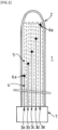
- thermocouple 1 illustrates a multipoint thermocouple 1, which is in the form of an overall sheath comprising an envelope 2 made of a refractory metal alloy resistant to the surrounding conditions (high temperature, corrosion), of the Inconel® type for example, one end of which is closed, the opposite end being open, delimiting an interior space in which a plurality of thermocouples will be housed (five in the example presented in the figure, referenced 3a, 3b, .., 3e), each thermocouple being made up of a pair of metal conductors (referenced for the thermocouple 3a): a first conductor 4 represented by a continuous line and a second conductor 5 represented by a broken line, the two conductors being made up of materials of different electrical conductivities and connected at a point called the junction point (referenced 6a in the figure for the thermocouple 3a and 6e for the thermocouple 3e).
- thermocouples for each thermocouple (3a,..., 3e), for each pair of conductors, the junction point (i.e. 6a,..., 6e) constitutes the temperature sensor.
- the information received by the sensor will be transmitted along the conductors to the open end of the casing 2 where the pairs of conductors are connected to an instrumentation 7 (for example a voltmeter which for each of the thermocouples measures the potential difference created at the sensor at the junction between the 2 metals; coupled with a converter it makes it possible to calculate the corresponding temperature).
- instrumentation 7 for example a voltmeter which for each of the thermocouples measures the potential difference created at the sensor at the junction between the 2 metals; coupled with a converter it makes it possible to calculate the corresponding temperature).
- the multipoint measurement system is designed and the thermocouples are arranged in the sheath so that when the system is installed in the collector, the sensors (6a to 6e in the example in the figure) are placed at the precise longitudinal positions along the metal casing 2 corresponding to the predefined positions for the temperature measurements to be made.
- the number of pairs of conductors is chosen according to the needs (five is given here simply for illustration purposes).
- the number of tubes to be equipped is between one and the total number of tubes in the row.
- the diameter of the casing 2 will be a function of the number of thermocouples contained, a liner of a quarter inch (6.35 mm) outside diameter being able to contain up to 16 thermocouples.
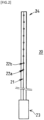
- FIG. 2 illustrates a multipoint temperature measurement system 20 of the optical fiber type with Bragg gratings comprising a very thin optical fiber 21 (diameter of the order of 0.1 mm) within which are inscribed Bragg gratings (22a, 22b, ...) acting as measurement points.
- Each Bragg grating is associated with a wavelength, typically in the range 1400-1700 nm.
- the Bragg gratings are wavelength multiplexed and can be interrogated simultaneously by an interrogator-type instrumentation 23.
- the optical fiber and Bragg grating assembly is protected in a metal casing 24, resistant to severe conditions (temperatures up to 950°C, pressure around 30 bar and typical composition of a syngas with mainly H 2 , CO and residues).
- the main interest of a multipoint temperature measurement system of the optical fiber type equipped with Bragg gratings lies in its very small size independent of the number of gratings inscribed in the fiber.
- FIG 3 illustrates a device 30 for collecting synthesis gas (syngas) S produced in the reforming tubes 31 of a row of tubes of an SMR reformer. Only one row of tubes and one longitudinal collector 32 are shown in the figure; in practice, the number of longitudinal collectors corresponds to the number of rows of tubes in the furnace. Each outlet tube opens into the longitudinal collector 32 which thus collects all of the syngas S produced by the tubes of the row.
- the tubes are connected to the collector 32 either directly or via a connecting piece.
- the connecting piece may have different shapes, it may be rectilinear and in this case end vertically in the longitudinal collector (as in the figure), or not, in this case it ends in the collector at an angle to the vertical.
- each longitudinal collector 32 therefore has one end opening into the transverse collector 33, its other end (not shown) being closed by a flange.
- FIG 4 illustrates a multipoint measuring system according to the invention.
- the measuring means 40 equipping a syngas collection device of the type of that of the previous figure for collecting the syngas produced by five tubes.
- the measuring means 40 is arranged in the collector 32 where, for each of the tubes for which the syngas temperature at the tube outlet is to be determined - that is to say in the example of the figure for four tubes, no measurement is made for the 2nd tube from the left in the figure - the system acquires the data by means of the sensors 41 positioned in the syngas at the outlet of the tubes.
- This first part of the measuring means comprises four surface temperature sensors, positioned in the synthesis gas at the outlet of the tubes for which the temperature of the synthesis gas at the tube outlet is measured.
- the measuring means 40 extends beyond this first part by a second part which has the function of transporting all of the acquired data beyond the measuring zone, first into the collector 32, then passing into the transverse collector 33 and crossing the wall of the transverse collector 33 towards the outside (solution illustrated by the figure); an alternative solution would consist of crossing the flange 48 (solution not illustrated by the figure). In all cases, care must be taken to ensure that the seal is ensured when crossing the wall or the flange.
- the second part of the system crosses the wall of the transverse collector via a tapping means 44 welded at 45 to the collector.
- a means 42 ensures sealing when the multipoint measurement system passes through the wall.
- the conditions pressure, temperature, composition
- the multipoint measurement means can be connected in complete safety via a transfer cable 47 to the instrumentation 43 placed remotely, for example in the control room of the installation where the temperatures can be viewed.
- This transfer cable may, when the dimensions of the installation require it, have a length of the order of 100 m or more.
- a suitable instrumentation (of the converter or interrogator type known as such) equipped with a suitable interface will convert the information measured by the sensors into a temperature measurement.
- thermocouples it is possible, in particular in cases of use of thermocouples, to use a plurality of independent means instead of a multipoint system, this solution however being of interest only if the number of independent thermocouples to be installed in the collector is low, i.e. for reformers whose number of tubes (to be equipped) per row is limited, the size of a device using independent thermocouples becoming excessive if the number of thermocouples to be installed per row increases.
- the multipoint system will therefore be preferred, except in the case where we only want to know the syngas temperature at the tube outlet for a very limited number of tubes.
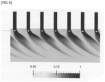
- FIG. 5 represents the results of a simulation of the behavior of the synthesis gas at the outlet of the tubes, carried out in order to determine the position relative to the outlet of a tube in the collector at which a sensor had to be placed to collect in the fluid circulating at this location data representative of the syngas leaving the tube - that is to say without there having been any prior mixing of the synthesis gas leaving the tube with that coming from the neighboring tubes and/or circulating in the collector.
- the objective of the simulation was therefore to highlight in the collector at the tube outlet an area in which the synthesis gas leaving the tube has not yet mixed with the synthesis gas coming from the other tubes; the simulation thus highlights an area where the measured temperature will be that of the synthesis gas at the outlet of the tube in the collector. This is where the sensor will be positioned.
- a tracer was injected (its presence is highlighted by the black color in the figure) at the inlet of the tubes and the behavior of the tracer at the outlet of the tubes was observed, so as to highlight the existence of a zone of non-mixing of the fluids in the collector in the immediate vicinity of the outlet of the tube, where the tracer had not yet mixed with the gas present in the collector.
- the tracer thus makes it possible to visualize the origin of the synthesis gas.
- the diameter to be taken into account is the diameter of the tube (or of the connecting part when there is one) at the outlet in the collector and not that of the tube in the part containing the reforming catalyst.
- the tube outlet is via a connecting piece which ends in the collector at an angle to the vertical
- the direction of the "tube outlet axis" which is also the direction of the gas flow produced in the tube where it enters the collector is defined by this same angle and the positioning distance of the sensor is measured in this direction.
- the drawings of the figure 6 present two schematic examples (a) and (b) of means for fixing the measuring means in the collector. These fixing means ensure the positioning of the entire measuring means in the collector, and in particular position the various temperature sensors at the outlet of the reforming tubes, in the outlet axis of the tubes and at the chosen distance.
- the sensor is arranged in the collector 32 vertically to the axis of the tube of which it measures the syngas temperature at the tube outlet.
- the positioning is ensured by a fixing cable 60 (diameter of approximately 2 to 3 mm) connected to the catalyst support 61 (means ensuring the maintenance of the catalyst in the tube); it descends into the connecting piece 31 which vertically extends the reforming tube to the collector (distance of approximately 1 m to 1.5 m), then descends into the longitudinal collector 32 over a maximum length of 60 mm which corresponds to twice the internal diameter of the connecting piece (short distance which prevents the mixing of the synthesis gas leaving the tube with the synthesis gas from the collector or neighboring tubes).
- the cable is provided at its end with a support element 64 capable of receiving and maintaining the measuring means in position.
- the example of a support element presented here is in the form of a hook, the measuring means being fixed in the hollow of said hook.
- the fixing of the measuring system is carried out so as to ensure the correct positioning of all the sensors 41 of the system.
- the cable can be connected to any other metal part present in the tube, or fixed by welding or drilling to the wall of the tube or the connection part to the collector, provided that the length of the cable is adapted accordingly and that the fixing means (fixing point to the tube + cable combined with the geometry of the fixing element 64) ensure the alignment of the sensor 41 with the tube outlet axis.
- This method of fixing from an anchor point located in the tube (or in the connection part) is particularly suitable in the case where the tube ends vertically in the collector.
- the fixing cable 60 must be rigid and/or held so as to ensure the positioning of the sensor 41 in the tube outlet axis (remember that the shape of certain connection parts leads for example to a tube outlet along a horizontal axis).
- the measuring means has an external casing with a rigid external casing, the number of fixing points required to ensure its fixing in the collector will depend on its weight.
- Each tube is suitable for being equipped with a fixing means according to example (a), but the adjacent tubes are close (the distance between 2 tubes is approximately 300 mm) and it is not necessary to have fixing points so close together.
- the fixing means can be spaced from one to several meters without compromising the rigidity of the assembly.
- the measuring means is fixed to the walls of the collector. More precisely, the positioning part is here an assembly formed by a connecting part (bridge) 63 connecting a point on the internal wall of the longitudinal collector to the support element 64 capable of receiving and holding the measuring means in position; the fixing element 64 presented is a U-shaped part, the measuring system being fixed in the hollow of said part (this is obviously only an example of a shape).
- connection between the collector wall and the fixing member can be made from a single point on the collector wall in the form of a support bridge (rigid elongated part connecting the collector wall to the part 64 receiving the measuring system of circular (or other) section with a diameter (or section) similar to the diameter of the measuring system (i.e. of the order of 5 mm for a system with thermocouple), or from several points, the section of the connecting parts being able in this case to be smaller.
- the support bridge 63 will preferably be one (or more) ceramic part(s) fixed to the internal wall of the collector 32 by a high-temperature refractory glue.
- metal elements will be used: the support bridge 63 will be one (or more) metal part(s) (pipe, bar, etc.) which can be welded directly to the internal wall of the collector.
- successive support bridges will be positioned in a staggered pattern (one on the left, one on the right), either between two or more tubes spaced 0.5 meters to several meters apart. It should be noted that this method of attachment is independent of the method of connecting the reforming tubes to the collector, whether it is done vertically to the collector or at an angle to the vertical.
- the invention is not limited to this arrangement in which the tubes are arranged in parallel rows, each being connected to a syngas collector, it may be applied for example to the syngas collectors of cylindrical reformers.
- the reforming tubes placed vertically in a circular arrangement are connected at their outlet to a single ring-shaped collector.
- the syngas is evacuated via a recovery pipe.
- the temperature measurement system according to the invention can be installed in the circular collector in the same way as in a rectilinear collector, the same sensor positioning means can be used.
- the transfer of the measured data outside the collector can be done via a sealed outlet through a wall of the collector with connection to the transfer cable as previously described.
Landscapes
- Chemical & Material Sciences (AREA)
- Chemical Kinetics & Catalysis (AREA)
- Organic Chemistry (AREA)
- Physics & Mathematics (AREA)
- General Physics & Mathematics (AREA)
- Health & Medical Sciences (AREA)
- General Health & Medical Sciences (AREA)
- Engineering & Computer Science (AREA)
- Combustion & Propulsion (AREA)
- Inorganic Chemistry (AREA)
- Hydrogen, Water And Hydrids (AREA)
Claims (13)
- System zur Messung einer spezifischen Temperatur für mindestens ein Reformierungsrohr, das in einem Methan-Dampfreformierungsofen vorhanden ist, wobei:• Reformierungsrohre, die vertikal in Reihen angeordnet sind, am Eingang mit Reaktionsgasgemisch gespeist werden und am Rohrausgang ein Synthesegas erzeugen,• ein Satz von längs verlaufenden rohrförmigen Sammlern in einer zu den Reihen von Rohren senkrechten Ebene angeordnet ist, unter diesen Reihen, um das erzeugte Synthesegas zu sammeln, wobei die Rohre einer gegebenen Reihe in einen längs verlaufenden Sammler münden, der ihr zugeordnet ist, wobei der Satz der längs verlaufenden Sammler in einen quer verlaufenden Sammler mündet, wobei der Satz der längs verlaufenden Sammler und der quer verlaufende Sammler das Sammelsystem des Synthesegases bilden,dadurch gekennzeichnet, dass das System für mindestens eine Reihe von Rohren mindestens umfasst:• ein Messmittel für mindestens eine Temperatur von aus dem Rohr austretendem Synthesegas, wobei das Mittel in der Länge des dieser Reihe von Rohren zugeordneten Sammlers angeordnet ist und mindestens umfasst:o einen ersten Teil von rohrförmiger Gestalt, der in der Länge des längs verlaufenden Sammlers angeordnet ist und mit mindestens einem Temperatursensor ausgestattet ist, um Temperaturdaten zu erfassen, wobei dieser Sensor im Synthesegas an der Mündung eines Reformierungsrohres der Reihe positioniert ist, von dem die Temperatur des austretenden Synthesegases gemessen wird;o einen den ersten Teil verlängernden zweiten Teil, der geeignet ist, die Übertragung der von dem Sensor erfassten Temperaturdaten aus dem längs verlaufenden Sammler hinaus und bis zum dritten Teil sicherzustellen;o einen dritten Teil, der Instrumente zum Berechnen der Temperatur aus den Daten umfasst, die vom ersten Teil des Mittels erfasst und vom zweiten Teil des Mittels übertragen wurden;• ein Mittel zur Positionierung des Temperatursensors in dem längs verlaufenden Sammler, das seine Positionierung in dem Strom von Synthesegas an der Mündung des Rohres sicherstellt, bevor seine Mischung mit dem von den anderen in den Sammler mündenden Rohren kommenden Synthesegas erfolgt;• ein dichtes Austrittsmittel des zweiten Teils des Messmittels zur Außenseite des Sammelsystems des Synthesegases hin.
- System zur Messung nach Anspruch 1, wobei das System für mindestens eine Reihe von Rohren ein oder mehrere Messmittel umfasst, von denen der erste Teil mit einem einzigen Temperatursensor ausgestattet ist, der an der Mündung eines Rohres, von dem er die Temperatur des austretenden Synthesegases misst, mithilfe eines dafür vorgesehenen Positionierungsmittels positioniert ist, und von denen der zweite Teil, der den ersten verlängert und geeignet ist, die Übertragung der von dem Sensor erfassten Temperaturdaten zu den Instrumenten sicherzustellen, über ein dichtes Austrittsmittel zur Außenseite des Sammelsystems des Synthesegases hin verfügt.
- System zur Messung nach Anspruch 1, wobei das in der Länge des längs verlaufenden Sammlers angeordnete Messmittel ein Mittel zur Mehrpunktmessung ist, das mehrere Sensoren aufweist, die entlang des ersten Teils des Messmittels angeordnet sind, um an den Mündungen der Rohre platziert zu werden, von denen die Temperatur des austretenden Synthesegases gemessen wird.
- System zur Messung nach einem der Ansprüche 1 bis 3, wobei der Sensor, der die Temperatur des aus einem Reformierungsrohr austretenden Synthesegases misst, in dem Sammler in der Achse des Rohres an seiner Mündung in den Sammler in einem von der Mündung des Rohres in den Sammler aus gemessenen maximalen Abstand positioniert ist, der gleich dem Zweifachen des an seiner Mündung in den Sammler gemessenen Innendurchmessers des Rohres ist.
- System nach Anspruch 4, dadurch gekennzeichnet, dass die Positionierung der Sensoren über mehrere entlang des ersten Teils des Temperaturmessmittels verteilte einzelne Befestigungsmittel sichergestellt ist, welche die Gesamtbefestigung des Messmittels am Sammler an seinem ersten Teil sicherstellen.
- System nach Anspruch 5, dadurch gekennzeichnet, dass die einzelnen Befestigungsmittel, welche die Gesamtbefestigung sicherstellen, ein Stützelement, auf dem das Messmittel ruht, und ein Positionierungsteil, das starr mit dem Stützelement und mit mindestens einem festen Punkt des Sammlers oder eines in den Sammler mündenden Reformierungsrohres verbunden ist, umfassen.
- System nach Anspruch 6, wobei das Positionierungsteil aus einem oder mehreren starren Teilen besteht, die das Stützelement mit den Wänden des Sammlers verbinden und so seine Zentrierung und sein Halten in Position sicherstellen.
- System nach Anspruch 6, wobei das Befestigungsmittel an einem vertikal in den Sammler führenden Rohrausgang positioniert ist, wobei das Positionierungsteil aus einer starren Achse besteht, die an ihrem oberen Ende mit dem Rohr durch Befestigung an der Innenwand des Rohres oder an einem seinerseits mit dem Rohr fest verbundenen Element, zum Beispiel an einer Katalysatorhalterung, fest verbunden ist und an ihrem unteren Ende mit einem Stützelement, auf dem das Messmittel ruht, fest verbunden ist.
- System nach einem der vorhergehenden Ansprüche, wobei der zweite Teil des Messmittels zur Außenseite des Sammelsystems des Synthesegases direkt von einem Ende des längs verlaufenden Sammlers aus austritt, das durch einen Flansch verschlossen ist, wobei der Flansch mit dem dichten Austrittsmittel des zweiten Teils des Messmittels zur Außenseite des Sammelsystems des Synthesegases hin ausgestattet ist.
- System nach einem der Ansprüche 1 bis 8, wobei der zweite Teil des Messmittels zur Außenseite des Sammelsystems des Synthesegases austritt, indem er durch den quer verlaufenden Sammler verläuft, der mit dem längs verlaufenden Sammler verbunden ist, und indem er die Wand des quer verlaufenden Sammlers durchquert, wobei diese Wand für diese Durchführung mit einem dichten Austrittsmittel des zweiten Teils des Messmittels zur Außenseite des Sammelsystems des Synthesegases hin ausgestattet ist.
- System nach einem der Ansprüche 1 oder 3 bis 10, wobei das Temperaturmessmittel vom Typ eines mit einem Bragg-Gitter ausgestatteten Lichtwellenleiters ist.
- System nach einem der Ansprüche 1 bis 10, wobei der verwendete Temperatursensor vom Typ eines Thermoelements ist.
- Verfahren zur Messung einer spezifischen Temperatur für mindestens ein Reformierungsrohr, bei dem ein System zur Temperaturmessung nach einem der vorhergehenden Ansprüche eingesetzt wird und gemäß dem die Temperatur des Synthesegases am Ausgang mindestens eines Reformierungsrohres mindestens einer Reihe von Rohren, die in einem Methan-Dampfreformierungsofen vorhanden sind, gemessen wird, wobei:• Reformierungsrohre, die vertikal in Reihen angeordnet sind, mit gasförmigem Kohlenwasserstoff und Wasserdampf gespeist werden und• am unteren Ausgang der Rohre das Synthesegas rückgewonnen wird,• das Synthesegas in einem längs verlaufenden Sammler gesammelt wird, der unter der Reihe von Rohren angeordnet ist, die ihm zugeordnet ist, wobei der Satz der längs verlaufenden Sammler in einen quer verlaufenden Sammler mündet,dadurch gekennzeichnet, dass für mindestens ein Rohr mindestens einer Reihe von Rohren Temperatur des aus dem Rohr austretenden Synthesegases gemessen wird, indem mindestens eingesetzt werden:• ein Messmittel, das in der Länge des der Reihe von Rohren zugeordneten Sammlers angeordnet ist, wobei das Mittel mindestens umfasst:o einen ersten Teil von rohrförmiger Gestalt, der in der Länge des längs verlaufenden Sammlers angeordnet ist und mit mindestens einem Temperatursensor ausgestattet ist, um Temperaturdaten zu erfassen, wobei dieser Sensor im Synthesegas an der Mündung eines Reformierungsrohres der Reihe positioniert ist, von dem die Temperatur des austretenden Synthesegases gemessen wird;o einen den ersten Teil verlängernden zweiten Teil, der geeignet ist, die Übertragung der von dem Sensor erfassten Temperaturdaten aus dem längs verlaufenden Sammler hinaus und bis zum dritten Teil sicherzustellen;o einen dritten Teil, der Instrumente zum Berechnen der Temperatur aus den Daten umfasst, die vom ersten Teil des Mittels erfasst und vom zweiten Teil des Mittels übertragen wurden;• ein Mittel zur Positionierung des Temperatursensors in dem längs verlaufenden Sammler, das seine Positionierung in dem Strom von Synthesegas an der Mündung des Rohres sicherstellt, bevor seine Mischung mit dem von den anderen in den Sammler mündenden Rohren kommenden Synthesegas erfolgt;• ein dichtes Austrittsmittel des zweiten Teils des Messmittels zur Außenseite des Sammelsystems des Synthesegases hin.
Applications Claiming Priority (2)
| Application Number | Priority Date | Filing Date | Title |
|---|---|---|---|
| FR2011036A FR3115595B1 (fr) | 2020-10-28 | 2020-10-28 | Système de mesure de température du gaz de synthèse en sortie de tube de reformage. |
| PCT/EP2021/079032 WO2022090009A1 (fr) | 2020-10-28 | 2021-10-20 | Système de mesure de température du gaz de synthèse en sortie de tube de reformage |
Publications (2)
| Publication Number | Publication Date |
|---|---|
| EP4237808A1 EP4237808A1 (de) | 2023-09-06 |
| EP4237808B1 true EP4237808B1 (de) | 2024-12-04 |
Family
ID=74045814
Family Applications (1)
| Application Number | Title | Priority Date | Filing Date |
|---|---|---|---|
| EP21798333.7A Active EP4237808B1 (de) | 2020-10-28 | 2021-10-20 | System zur messung der temperatur des aus einem reformierungsrohr austretenden syngases |
Country Status (6)
| Country | Link |
|---|---|
| US (1) | US20240344900A1 (de) |
| EP (1) | EP4237808B1 (de) |
| KR (1) | KR20230095972A (de) |
| CN (1) | CN116615639A (de) |
| FR (1) | FR3115595B1 (de) |
| WO (1) | WO2022090009A1 (de) |
Families Citing this family (1)
| Publication number | Priority date | Publication date | Assignee | Title |
|---|---|---|---|---|
| EP4715355A1 (de) * | 2024-09-18 | 2026-03-25 | Technip Energies France | System zur messung der temperatur einer gasverarbeitung |
Family Cites Families (3)
| Publication number | Priority date | Publication date | Assignee | Title |
|---|---|---|---|---|
| FR2888920B1 (fr) * | 2005-07-19 | 2013-07-05 | Air Liquide | Procede de maintenance des tubes de catalyseur d'un reformeur d'hydrocarbures |
| ES2347833T3 (es) * | 2007-01-09 | 2010-11-04 | L'air Liquide, Societe Anonyme Pour L'etude Et L'exploitation Des Procedes Georges Claude | Procedimiento de sustitucion de los tubos de catalizdor de un reformador de hidrocarburos. |
| US11815408B2 (en) * | 2019-02-11 | 2023-11-14 | Wika Alexander Wiegand Se & Co. Kg | Temperature sensing device |
-
2020
- 2020-10-28 FR FR2011036A patent/FR3115595B1/fr active Active
-
2021
- 2021-10-20 KR KR1020237015173A patent/KR20230095972A/ko not_active Withdrawn
- 2021-10-20 CN CN202180072453.3A patent/CN116615639A/zh not_active Withdrawn
- 2021-10-20 EP EP21798333.7A patent/EP4237808B1/de active Active
- 2021-10-20 WO PCT/EP2021/079032 patent/WO2022090009A1/fr not_active Ceased
- 2021-10-20 US US18/034,485 patent/US20240344900A1/en active Pending
Also Published As
| Publication number | Publication date |
|---|---|
| CN116615639A (zh) | 2023-08-18 |
| FR3115595A1 (fr) | 2022-04-29 |
| EP4237808A1 (de) | 2023-09-06 |
| FR3115595B1 (fr) | 2022-09-09 |
| KR20230095972A (ko) | 2023-06-29 |
| WO2022090009A1 (fr) | 2022-05-05 |
| US20240344900A1 (en) | 2024-10-17 |
Similar Documents
| Publication | Publication Date | Title |
|---|---|---|
| EP2394735B1 (de) | Wechselreaktor mit Bajonettrohren und Rauchrohren, die am oberen Deckengewölbe des Reaktors aufgehängt sind | |
| EP2877819B1 (de) | Verfahren und vorrichtung zur messung des gehaltes an gusseisen und schlacke in einem hochofen | |
| FR2715583A1 (fr) | Dispositif pour la mise en Óoeuvre de réactions chimiques nécessitant au moins au démarrage un apport de calories. | |
| EP4237808B1 (de) | System zur messung der temperatur des aus einem reformierungsrohr austretenden syngases | |
| FR2702831A1 (fr) | Procédé et dispositif de refroidissement de l'enceinte d'un échangeur thermique. | |
| EP0066516A1 (de) | Einrichtung zur Überwachung des Kühlmittelzustandes in einem Kernreaktor | |
| EP2101906A1 (de) | Verfahren zum ersatz der katalysatorröhren eines kohlenwasserstoff-reformers | |
| FR3019932A1 (fr) | Detecteur de neutrons autoalimentes d'un reacteur a eau pressurisee | |
| EP0272944B1 (de) | Führungs- und Positionierungsrohr für Spaltzonenmessvorrichtung eines Kernreaktors | |
| CN101021439A (zh) | 钢水温度快速响应红外连续测量装置 | |
| CN116612909B (zh) | 核反应堆燃料棒束事故失效行为研究的实验装置及方法 | |
| CA2460622A1 (fr) | Dispositif et methode de liaison a etancheite relative et controlee entre un conduit et un tube ceramique | |
| EP3724128B1 (de) | Vorrichtung zur messung der innentemperatur eines reformierungsrohrs | |
| EP2999949B1 (de) | Wärmeflusssensor | |
| EP0751531A2 (de) | Vorrichtung zur Messung wenigstens eines physikalischen Parameters innerhalb des Kerns eines nuklearen Reaktors | |
| EP3173761A1 (de) | Elektrisches koaxialkabel, mit einem solchen kabel ausgestattete detektionsvorrichtung zum auffinden von flüssigkeitslecks, die aus einer leitung austreten, und entsprechendes detektionsverfahren | |
| CN102203586A (zh) | 腐蚀检测探测器 | |
| FR2802119A1 (fr) | Dispositif de liaison entre un tube destine au chauffage et/ ou au refroidissement d'un reacteur sous pression et ledit reacteur | |
| FR3143742A1 (fr) | Méthode de suivi de fonctionnement d’une installation de production d’un gaz de synthèse. | |
| FR2732014A1 (fr) | Procede de conversion thermique d'hydrocarbures aliphatiques satures ou insatures en hydrocarbures acetyleniques | |
| EP0024985B1 (de) | Spaltprodukte emittierende Eichvorrichtung zum Eichen einer Einrichtung zum Feststellen von Hüllenschäden in Kernreaktoren | |
| EP0285464A1 (de) | Erhitzungsvorrichtung, insbesondere zur Wärmebehandlung von gebogenen Rohren mit niedrigem Durchmesser | |
| WO2015011415A1 (fr) | Sonde de controle de l'encrassement et de la corrosion pour un echangeur a chaleur tubulaire et procede utilisant une telle sonde | |
| FR2733050A1 (fr) | Procede et dispositif de mesure de la concentration de gaz dans un melange gazeux a l'interieur d'un batiment reacteur d'une centrale nucleaire et utilisation | |
| FR3104715A1 (fr) | Méthode de contrôle non destructif du vieillissement d’un réacteur de reformage. |
Legal Events
| Date | Code | Title | Description |
|---|---|---|---|
| STAA | Information on the status of an ep patent application or granted ep patent |
Free format text: STATUS: UNKNOWN |
|
| STAA | Information on the status of an ep patent application or granted ep patent |
Free format text: STATUS: THE INTERNATIONAL PUBLICATION HAS BEEN MADE |
|
| PUAI | Public reference made under article 153(3) epc to a published international application that has entered the european phase |
Free format text: ORIGINAL CODE: 0009012 |
|
| STAA | Information on the status of an ep patent application or granted ep patent |
Free format text: STATUS: REQUEST FOR EXAMINATION WAS MADE |
|
| 17P | Request for examination filed |
Effective date: 20230530 |
|
| AK | Designated contracting states |
Kind code of ref document: A1 Designated state(s): AL AT BE BG CH CY CZ DE DK EE ES FI FR GB GR HR HU IE IS IT LI LT LU LV MC MK MT NL NO PL PT RO RS SE SI SK SM TR |
|
| DAV | Request for validation of the european patent (deleted) | ||
| DAX | Request for extension of the european patent (deleted) | ||
| GRAP | Despatch of communication of intention to grant a patent |
Free format text: ORIGINAL CODE: EPIDOSNIGR1 |
|
| STAA | Information on the status of an ep patent application or granted ep patent |
Free format text: STATUS: GRANT OF PATENT IS INTENDED |
|
| INTG | Intention to grant announced |
Effective date: 20240603 |
|
| GRAJ | Information related to disapproval of communication of intention to grant by the applicant or resumption of examination proceedings by the epo deleted |
Free format text: ORIGINAL CODE: EPIDOSDIGR1 |
|
| STAA | Information on the status of an ep patent application or granted ep patent |
Free format text: STATUS: REQUEST FOR EXAMINATION WAS MADE |
|
| INTC | Intention to grant announced (deleted) | ||
| GRAP | Despatch of communication of intention to grant a patent |
Free format text: ORIGINAL CODE: EPIDOSNIGR1 |
|
| STAA | Information on the status of an ep patent application or granted ep patent |
Free format text: STATUS: GRANT OF PATENT IS INTENDED |
|
| GRAS | Grant fee paid |
Free format text: ORIGINAL CODE: EPIDOSNIGR3 |
|
| GRAA | (expected) grant |
Free format text: ORIGINAL CODE: 0009210 |
|
| STAA | Information on the status of an ep patent application or granted ep patent |
Free format text: STATUS: THE PATENT HAS BEEN GRANTED |
|
| INTG | Intention to grant announced |
Effective date: 20241009 |
|
| AK | Designated contracting states |
Kind code of ref document: B1 Designated state(s): AL AT BE BG CH CY CZ DE DK EE ES FI FR GB GR HR HU IE IS IT LI LT LU LV MC MK MT NL NO PL PT RO RS SE SI SK SM TR |
|
| REG | Reference to a national code |
Ref country code: CH Ref legal event code: EP |
|
| REG | Reference to a national code |
Ref country code: DE Ref legal event code: R096 Ref document number: 602021022985 Country of ref document: DE |
|
| REG | Reference to a national code |
Ref country code: IE Ref legal event code: FG4D Free format text: LANGUAGE OF EP DOCUMENT: FRENCH |
|
| REG | Reference to a national code |
Ref country code: NL Ref legal event code: FP |
|
| REG | Reference to a national code |
Ref country code: LT Ref legal event code: MG9D |
|
| PG25 | Lapsed in a contracting state [announced via postgrant information from national office to epo] |
Ref country code: HR Free format text: LAPSE BECAUSE OF FAILURE TO SUBMIT A TRANSLATION OF THE DESCRIPTION OR TO PAY THE FEE WITHIN THE PRESCRIBED TIME-LIMIT Effective date: 20241204 |
|
| PG25 | Lapsed in a contracting state [announced via postgrant information from national office to epo] |
Ref country code: FI Free format text: LAPSE BECAUSE OF FAILURE TO SUBMIT A TRANSLATION OF THE DESCRIPTION OR TO PAY THE FEE WITHIN THE PRESCRIBED TIME-LIMIT Effective date: 20241204 |
|
| PG25 | Lapsed in a contracting state [announced via postgrant information from national office to epo] |
Ref country code: BG Free format text: LAPSE BECAUSE OF FAILURE TO SUBMIT A TRANSLATION OF THE DESCRIPTION OR TO PAY THE FEE WITHIN THE PRESCRIBED TIME-LIMIT Effective date: 20241204 |
|
| PG25 | Lapsed in a contracting state [announced via postgrant information from national office to epo] |
Ref country code: ES Free format text: LAPSE BECAUSE OF FAILURE TO SUBMIT A TRANSLATION OF THE DESCRIPTION OR TO PAY THE FEE WITHIN THE PRESCRIBED TIME-LIMIT Effective date: 20241204 |
|
| PG25 | Lapsed in a contracting state [announced via postgrant information from national office to epo] |
Ref country code: NO Free format text: LAPSE BECAUSE OF FAILURE TO SUBMIT A TRANSLATION OF THE DESCRIPTION OR TO PAY THE FEE WITHIN THE PRESCRIBED TIME-LIMIT Effective date: 20250304 |
|
| PG25 | Lapsed in a contracting state [announced via postgrant information from national office to epo] |
Ref country code: LV Free format text: LAPSE BECAUSE OF FAILURE TO SUBMIT A TRANSLATION OF THE DESCRIPTION OR TO PAY THE FEE WITHIN THE PRESCRIBED TIME-LIMIT Effective date: 20241204 Ref country code: GR Free format text: LAPSE BECAUSE OF FAILURE TO SUBMIT A TRANSLATION OF THE DESCRIPTION OR TO PAY THE FEE WITHIN THE PRESCRIBED TIME-LIMIT Effective date: 20250305 |
|
| PG25 | Lapsed in a contracting state [announced via postgrant information from national office to epo] |
Ref country code: RS Free format text: LAPSE BECAUSE OF FAILURE TO SUBMIT A TRANSLATION OF THE DESCRIPTION OR TO PAY THE FEE WITHIN THE PRESCRIBED TIME-LIMIT Effective date: 20250304 |
|
| REG | Reference to a national code |
Ref country code: AT Ref legal event code: MK05 Ref document number: 1748628 Country of ref document: AT Kind code of ref document: T Effective date: 20241204 |
|
| PG25 | Lapsed in a contracting state [announced via postgrant information from national office to epo] |
Ref country code: SM Free format text: LAPSE BECAUSE OF FAILURE TO SUBMIT A TRANSLATION OF THE DESCRIPTION OR TO PAY THE FEE WITHIN THE PRESCRIBED TIME-LIMIT Effective date: 20241204 |
|
| PG25 | Lapsed in a contracting state [announced via postgrant information from national office to epo] |
Ref country code: PL Free format text: LAPSE BECAUSE OF FAILURE TO SUBMIT A TRANSLATION OF THE DESCRIPTION OR TO PAY THE FEE WITHIN THE PRESCRIBED TIME-LIMIT Effective date: 20241204 |
|
| PG25 | Lapsed in a contracting state [announced via postgrant information from national office to epo] |
Ref country code: IS Free format text: LAPSE BECAUSE OF FAILURE TO SUBMIT A TRANSLATION OF THE DESCRIPTION OR TO PAY THE FEE WITHIN THE PRESCRIBED TIME-LIMIT Effective date: 20250404 |
|
| PG25 | Lapsed in a contracting state [announced via postgrant information from national office to epo] |
Ref country code: PT Free format text: LAPSE BECAUSE OF FAILURE TO SUBMIT A TRANSLATION OF THE DESCRIPTION OR TO PAY THE FEE WITHIN THE PRESCRIBED TIME-LIMIT Effective date: 20250404 |
|
| PG25 | Lapsed in a contracting state [announced via postgrant information from national office to epo] |
Ref country code: EE Free format text: LAPSE BECAUSE OF FAILURE TO SUBMIT A TRANSLATION OF THE DESCRIPTION OR TO PAY THE FEE WITHIN THE PRESCRIBED TIME-LIMIT Effective date: 20241204 |
|
| PG25 | Lapsed in a contracting state [announced via postgrant information from national office to epo] |
Ref country code: AT Free format text: LAPSE BECAUSE OF FAILURE TO SUBMIT A TRANSLATION OF THE DESCRIPTION OR TO PAY THE FEE WITHIN THE PRESCRIBED TIME-LIMIT Effective date: 20241204 Ref country code: RO Free format text: LAPSE BECAUSE OF FAILURE TO SUBMIT A TRANSLATION OF THE DESCRIPTION OR TO PAY THE FEE WITHIN THE PRESCRIBED TIME-LIMIT Effective date: 20241204 |
|
| PG25 | Lapsed in a contracting state [announced via postgrant information from national office to epo] |
Ref country code: SK Free format text: LAPSE BECAUSE OF FAILURE TO SUBMIT A TRANSLATION OF THE DESCRIPTION OR TO PAY THE FEE WITHIN THE PRESCRIBED TIME-LIMIT Effective date: 20241204 |
|
| PG25 | Lapsed in a contracting state [announced via postgrant information from national office to epo] |
Ref country code: CZ Free format text: LAPSE BECAUSE OF FAILURE TO SUBMIT A TRANSLATION OF THE DESCRIPTION OR TO PAY THE FEE WITHIN THE PRESCRIBED TIME-LIMIT Effective date: 20241204 |
|
| PG25 | Lapsed in a contracting state [announced via postgrant information from national office to epo] |
Ref country code: IT Free format text: LAPSE BECAUSE OF FAILURE TO SUBMIT A TRANSLATION OF THE DESCRIPTION OR TO PAY THE FEE WITHIN THE PRESCRIBED TIME-LIMIT Effective date: 20241204 |
|
| REG | Reference to a national code |
Ref country code: DE Ref legal event code: R097 Ref document number: 602021022985 Country of ref document: DE |
|
| PG25 | Lapsed in a contracting state [announced via postgrant information from national office to epo] |
Ref country code: SE Free format text: LAPSE BECAUSE OF FAILURE TO SUBMIT A TRANSLATION OF THE DESCRIPTION OR TO PAY THE FEE WITHIN THE PRESCRIBED TIME-LIMIT Effective date: 20241204 |
|
| PG25 | Lapsed in a contracting state [announced via postgrant information from national office to epo] |
Ref country code: DK Free format text: LAPSE BECAUSE OF FAILURE TO SUBMIT A TRANSLATION OF THE DESCRIPTION OR TO PAY THE FEE WITHIN THE PRESCRIBED TIME-LIMIT Effective date: 20241204 |
|
| PLBE | No opposition filed within time limit |
Free format text: ORIGINAL CODE: 0009261 |
|
| STAA | Information on the status of an ep patent application or granted ep patent |
Free format text: STATUS: NO OPPOSITION FILED WITHIN TIME LIMIT |
|
| 26N | No opposition filed |
Effective date: 20250905 |