EP4237786B1 - Improvements in or relating to mine clearance - Google Patents
Improvements in or relating to mine clearance Download PDFInfo
- Publication number
- EP4237786B1 EP4237786B1 EP21785824.0A EP21785824A EP4237786B1 EP 4237786 B1 EP4237786 B1 EP 4237786B1 EP 21785824 A EP21785824 A EP 21785824A EP 4237786 B1 EP4237786 B1 EP 4237786B1
- Authority
- EP
- European Patent Office
- Prior art keywords
- deployable
- mine clearance
- clearance device
- blade
- deployed position
- Prior art date
- Legal status (The legal status is an assumption and is not a legal conclusion. Google has not performed a legal analysis and makes no representation as to the accuracy of the status listed.)
- Active
Links
Images






Classifications
-
- F—MECHANICAL ENGINEERING; LIGHTING; HEATING; WEAPONS; BLASTING
- F41—WEAPONS
- F41H—ARMOUR; ARMOURED TURRETS; ARMOURED OR ARMED VEHICLES; MEANS OF ATTACK OR DEFENCE, e.g. CAMOUFLAGE, IN GENERAL
- F41H11/00—Defence installations; Defence devices
- F41H11/12—Means for clearing land minefields; Systems specially adapted for detection of landmines
- F41H11/16—Self-propelled mine-clearing vehicles; Mine-clearing devices attachable to vehicles
- F41H11/20—Self-propelled mine-clearing vehicles; Mine-clearing devices attachable to vehicles with ground-penetrating elements, e.g. with means for removing buried landmines from the soil
- F41H11/24—Self-propelled mine-clearing vehicles; Mine-clearing devices attachable to vehicles with ground-penetrating elements, e.g. with means for removing buried landmines from the soil the elements being ploughs
Definitions
- the present invention relates generally to mine clearance and particularly, although not exclusively, to the clearance of surface laid or scattered mines, for example through the application of a lightweight and compact system.
- US20I5/362295 describes a wire neutralisation system for use with a vehicle.
- the system includes a blade movable between a stowed position and a deployed position. The blade ploughs through the terrain to disable buried wires when in the deployed position.
- EP0071384 describes a minefield clearing apparatus mountable on a vehicle.
- the present invention seeks to provide improvements in or relating to mine clearance.
- a deployable mine clearance device which comprises a support structure, a chassis and a plurality of blade members mounted to a chassis in a row and movable from a stowed position to a deployed position, said blade members being biased to the deployed position, said blade members comprising a front plate, a top link and a bottom link, each of them being connected to its neighbour by a hinge, creating, together with the chassis, a 4-bar linkage movable between said stowed position and said deployed position, wherein one or more of rows of blade members are arranged as a row assembly to form a straight or V-shaped clearance blade assembly, wherein the blade assembly is attachable to a host vehicle by the support structure, and wherein the support structure allows some movement of the blade assembly relative to the vehicle to enable it to contour the ground.
- the device is formed to provide a lightweight, folding clearance mechanism.
- Some embodiments allow for a mine clearance device to be fitted to nearly any vehicle, with minimal impact.
- the device could be worn as a "life-jacket" to protect against attack of scatterable mines and/or carried as a "lifeboat” to escape from a mined area, without the need for heavy engineering vehicles to accompany.
- the solution could, for example, be applied to front-line combat vehicles and/or to logistics vehicles.
- Each blade member may include a latch for locking the member in a deployed position.
- a restraining mechanism (such as a cover) may be provided to hold the device in the stowed position. When it is required the device can be released and members automatically move to the deployed position.
- the front plate has a stiffness to improve the tendency to collect and remove mines.
- a "tuned stiffness" aspect of blade front plate may be helpful to the action of the blade.
- the bottom link may act as a break-back, to prevent overload and damage.
- a "break-back bottom link” may be useful to a lightweight realisation of the concept and may tune strength to the application. Without this mechanism additional strength and mass may be required.
- the top link may act as a leaf-spring, to apply a push-down force on to the ground in use.
- a "leaf spring top link” may, for example, allows simple realisation of the mechanism, integrates the auto-deployment and automatic latching into the working position.
- Each member comprises a plurality of elements (a top link, a bottom link and a front plate).
- the elements are mounted on a chassis, the chassis may be considered as a blade member element.
- Each element of a member is connected to its neighbour by a hinge, forming a linkage, (with a chassis forming/being an element of member and/or the elements forming a working member mechanism in combination with a chassis).
- the cross-sectional area (e.g. defined as depth multiplied by height) of the working member/s in the stowed position may be 50% or less, 25% or less, or 10% or less than the cross-sectional area in the deployed position.
- the stowed position volume of the device may, for example, be less than 10% of the deployed position volume.
- the present invention also provides a vehicle, such as a military vehicle, fitted with one or more devices as described herein.
- Example embodiments are shown and described in sufficient detail to enable those of ordinary skill in the art to embody and implement the systems and processes herein described. It is important to understand that embodiments can be provided in many alternate forms and should not be construed as limited to the examples set forth herein.
- the working component of the clearance device members comprises three elements: the front plate (I), the top link (2), and the bottom link (3). This is also a latch (4) which locks the mechanism. These are mounted in a row, to a chassis (5).
- the chassis is common to all members in a row; in other embodiments separate chassis plates could be provided for each member. In some embodiments the chassis could also be considered as an element.
- Each element of a member is connected to its neighbour by a hinge, creating, together with the chassis, a 4-bar linkage which can fold away into a small package against the chassis or fold out into its working configuration when required.
- One or more of these row assemblies form a straight or V shaped clearance blade which is attached to a host vehicle by a suitable support structure. This structure is able to move the blade assembly between a stowed and a deployed position and when deployed the support structure allows some movement of the blade assembly relative to the vehicle to enable it to contour the ground.
- the linkage is arranged so that the front plate path (locus) is able to contour sharp steps, uneven ground, and changes in ground level.
- the linkage is designed for compact packaging, where the stowed package is ⁇ 10% of the deployed volume.
- the linkage will, when released from its stowed position, by release of a cover or other means, fall under gravity to open itself and remain in an operational position. When fully open a latch will be actuated and lock the top link to the chassis.
- a latch striker (4) is pushed rearward by a latch hook plate, which is integrated into the top link (3).
- the latch hook engages on the striker and locks the top link in position.
- the front plate has a specific stiffness, to improve the tendency to collect and remove mines. If the front plate is too stiff the impact forces are increased, requiring a stronger and heavier structure. If the front plate is too flexible it will tend to sweep over the mines without clearing them.
- the bottom link acts as a break-back, to prevent overload and damage to the blade, for example, when a rigid obstacle is encountered.
- the bottom link By acting through a buckling mechanism, the bottom link is rigid up until an overload force is reached, whereupon it will deflect.
- the top link acts as a leaf-spring, to apply a push-down force on to the ground. This keeps the bottom edge of the front plate in contact with the ground.
- the cross-sectional area defined as depth multiplied by height (D x H as illustrated in Fig 9 ) of the working member in the stowed position, is 25% or less than the cross-sectional area in the deployed position. In this embodiment, for example, stowed position is approximately 18% of the area of the deployed position.
Landscapes
- Life Sciences & Earth Sciences (AREA)
- Soil Sciences (AREA)
- Engineering & Computer Science (AREA)
- General Engineering & Computer Science (AREA)
- Aiming, Guidance, Guns With A Light Source, Armor, Camouflage, And Targets (AREA)
Description
- The present invention relates generally to mine clearance and particularly, although not exclusively, to the clearance of surface laid or scattered mines, for example through the application of a lightweight and compact system.
- Known surface clearance devices are bulky and heavy pieces of equipment which, when fitted, reduce the capability of the host vehicle.
-
US20I5/362295 -
EP0071384 describes a minefield clearing apparatus mountable on a vehicle. - The present invention seeks to provide improvements in or relating to mine clearance.
- According to the invention, a deployable mine clearance device is provided which comprises a support structure, a chassis and a plurality of blade members mounted to a chassis in a row and movable from a stowed position to a deployed position, said blade members being biased to the deployed position, said blade members comprising a front plate, a top link and a bottom link, each of them being connected to its neighbour by a hinge, creating, together with the chassis, a 4-bar linkage movable between said stowed position and said deployed position, wherein one or more of rows of blade members are arranged as a row assembly to form a straight or V-shaped clearance blade assembly, wherein the blade assembly is attachable to a host vehicle by the support structure, and wherein the support structure allows some movement of the blade assembly relative to the vehicle to enable it to contour the ground.
- In some embodiments the device is formed to provide a lightweight, folding clearance mechanism.
- Some embodiments allow for a mine clearance device to be fitted to nearly any vehicle, with minimal impact.
- In some embodiments the device could be worn as a "life-jacket" to protect against attack of scatterable mines and/or carried as a "lifeboat" to escape from a mined area, without the need for heavy engineering vehicles to accompany. The solution could, for example, be applied to front-line combat vehicles and/or to logistics vehicles.
- Each blade member may include a latch for locking the member in a deployed position. A restraining mechanism (such as a cover) may be provided to hold the device in the stowed position. When it is required the device can be released and members automatically move to the deployed position.
- In some embodiments the front plate has a stiffness to improve the tendency to collect and remove mines. A "tuned stiffness" aspect of blade front plate may be helpful to the action of the blade.
- The bottom link may act as a break-back, to prevent overload and damage. A "break-back bottom link" may be useful to a lightweight realisation of the concept and may tune strength to the application. Without this mechanism additional strength and mass may be required.
- The top link may act as a leaf-spring, to apply a push-down force on to the ground in use. A "leaf spring top link" may, for example, allows simple realisation of the mechanism, integrates the auto-deployment and automatic latching into the working position.
- Each member comprises a plurality of elements (a top link, a bottom link and a front plate). The elements are mounted on a chassis, the chassis may be considered as a blade member element.
- Each element of a member is connected to its neighbour by a hinge, forming a linkage, (with a chassis forming/being an element of member and/or the elements forming a working member mechanism in combination with a chassis).
- The cross-sectional area (e.g. defined as depth multiplied by height) of the working member/s in the stowed position, may be 50% or less, 25% or less, or 10% or less than the cross-sectional area in the deployed position. The stowed position volume of the device may, for example, be less than 10% of the deployed position volume.
- The present invention also provides a vehicle, such as a military vehicle, fitted with one or more devices as described herein.
- Different aspects and embodiments of the invention may be used separately or together.
- Further particular and preferred aspects of the present invention are set out in the accompanying independent and dependent claims. Features of the dependent claims may be combined with the features of the independent claims as appropriate, and in combination other than those explicitly set out in the claims. Each aspect can be carried out independently of the other aspects or in combination with one or more of the other aspects.
- The present invention will now be more particularly described, by way of example, with reference to the accompanying drawings, in which:
-
Figure I - the elements of the blade member; -
Figure 2 - a single row assembly comprising multiple blade members each including front plates, top and bottom links, mounted to a common chassis; -
Figure 3 - two row assemblies are mounted to a host vehicle by means of a boom and actuators; -
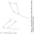
Figure 4 - (left) the blade member is folded (right) the member is unfolded and latched in place; -
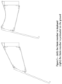
Figure 5 - (left) the blade member is deployed (right) the blade member is preloaded on the ground; -
Figure 6 - (left) the blade member is preloaded on the ground (right) the break-back bottom link buckles on overload; -
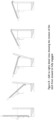
Figure 7 - (left to right) the motion of the latch from stowed to fully engaged; -
Figure 8 - (left to right) detail view showing the motion of the latch from stowed to fully engaged; and -
Figure 9 - calculating the "area" of the stowed and deployed working member. - Example embodiments are shown and described in sufficient detail to enable those of ordinary skill in the art to embody and implement the systems and processes herein described. It is important to understand that embodiments can be provided in many alternate forms and should not be construed as limited to the examples set forth herein.
- Accordingly, while embodiments can be modified in various ways and take on various alternative forms, specific embodiments thereof are shown in the drawings and described in detail below as examples. There is no intent to limit to the particular forms disclosed. On the contrary, all modifications, equivalents, and alternatives falling within the scope of the appended claims should be included. Elements of the example embodiments are consistently denoted by the same reference numerals throughout the drawings and detailed description where appropriate. The invention is not limited in the design and shape of the structure shown in the drawings.
- The terminology used herein to describe embodiments is not intended to limit the scope. The articles "a," "an," and "the" are singular in that they have a single referent, however the use of the singular form in the present document should not preclude the presence of more than one referent. In other words, elements referred to in the singular can number one or more, unless the context clearly indicates otherwise. It will be further understood that the terms "comprises," "comprising," "includes," and/or "including," when used herein, specify the presence of stated features, items, steps, operations, elements, and/or components, but do not preclude the presence or addition of one or more other features, items, steps, operations, elements, components, and/or groups thereof.
- Unless otherwise defined, all terms (including technical and scientific terms) used herein are to be interpreted as is customary in the art. It will be further understood that terms in common usage should also be interpreted as is customary in the relevant art and not in an idealized or overly formal sense unless expressly so defined herein.
- The working component of the clearance device members comprises three elements: the front plate (I), the top link (2), and the bottom link (3). This is also a latch (4) which locks the mechanism. These are mounted in a row, to a chassis (5). In this embodiment the chassis is common to all members in a row; in other embodiments separate chassis plates could be provided for each member. In some embodiments the chassis could also be considered as an element.
- Each element of a member is connected to its neighbour by a hinge, creating, together with the chassis, a 4-bar linkage which can fold away into a small package against the chassis or fold out into its working configuration when required. One or more of these row assemblies form a straight or V shaped clearance blade which is attached to a host vehicle by a suitable support structure. This structure is able to move the blade assembly between a stowed and a deployed position and when deployed the support structure allows some movement of the blade assembly relative to the vehicle to enable it to contour the ground.
- In this embodiment the linkage is arranged so that the front plate path (locus) is able to contour sharp steps, uneven ground, and changes in ground level.
- The linkage is designed for compact packaging, where the stowed package is <10% of the deployed volume.
- The linkage will, when released from its stowed position, by release of a cover or other means, fall under gravity to open itself and remain in an operational position. When fully open a latch will be actuated and lock the top link to the chassis.
- During opening a latch striker (4) is pushed rearward by a latch hook plate, which is integrated into the top link (3).
- When deployed, the latch striker is clear to return to the closed position.
- When the mechanism is loaded into the ground, the latch hook engages on the striker and locks the top link in position.
- The front plate has a specific stiffness, to improve the tendency to collect and remove mines. If the front plate is too stiff the impact forces are increased, requiring a stronger and heavier structure. If the front plate is too flexible it will tend to sweep over the mines without clearing them.
- The bottom link acts as a break-back, to prevent overload and damage to the blade, for example, when a rigid obstacle is encountered. By acting through a buckling mechanism, the bottom link is rigid up until an overload force is reached, whereupon it will deflect.
- The top link acts as a leaf-spring, to apply a push-down force on to the ground. This keeps the bottom edge of the front plate in contact with the ground.
- The cross-sectional area, defined as depth multiplied by height (D x H as illustrated in
Fig 9 ) of the working member in the stowed position, is 25% or less than the cross-sectional area in the deployed position. In this embodiment, for example, stowed position is approximately 18% of the area of the deployed position. - Although illustrative embodiments of the invention have been disclosed in detail herein, with reference to the accompanying drawings, it is understood that the invention is not limited to the precise embodiments shown and that various changes and modifications can be effected therein by one skilled in the art without departing from the scope of the invention as defined by the appended claims.
Claims (13)
- A deployable mine clearance device comprising a support structure, a chassis (5) and a plurality of blade members mounted to the chassis (5) in a row and movable from a stowed position to a deployed position, said blade members being biased to the deployed position, said blade members comprising a front plate (1), a top link (2) and a bottom link (3), each of them being connected to its neighbour by a hinge, creating, together with the chassis (5), a 4-bar linkage movable between said stowed position and said deployed position, wherein one or more of rows of blade members are arranged as a row assembly to form a straight or V-shaped clearance blade assembly, wherein the blade assembly is attachable to a host vehicle by the support structure, and wherein the support structure allows some movement of the blade assembly relative to the vehicle to enable it to contour the ground.
- A deployable mine clearance device as claimed in claim 1, in which the blade members include a latch (4) for locking the member in a deployed position.
- A deployable mine clearance device as claimed in claim 2, in which the front plate (1) has a stiffness to improve the tendency to collect and remove mines.
- A deployable mine clearance device as claimed in any preceding claim, in which the bottom link (3) is configured to buckle on overload.
- A deployable mine clearance device as claimed in any preceding claim, in which the top link (2) acts as a leaf-spring, to apply a push-down force on to the ground in use.
- A deployable mine clearance device as claimed in any preceding claim comprising a restraining mechanism to hold the device in the stowed position.
- A deployable mine clearance device as claimed in claim 6, in which the restraining mechanism is a cover.
- A deployable mine clearance device as claimed in any preceding claim, in which in the stowed position the front plate folds flat against the chassis.
- A deployable mine clearance device as claimed in any preceding claim, in which the cross-sectional area of each blade member in the stowed position is 50% or less than the cross-sectional area in the deployed position.
- A deployable mine clearance device as claimed in any preceding claim, in which the cross-sectional area of each blade member in the stowed position is 25% or less than the cross-sectional area in the deployed position.
- A deployable mine clearance device as claimed in any preceding claim, in which the cross-sectional area of each blade member in the stowed position is 10% or less than the cross-sectional area in the deployed position.
- A deployable mine clearance device as claimed in any preceding claim, in which the stowed position volume is less than 10% of the deployed position volume.
- A vehicle fitted with one or more deployable mine clearance devices as claimed in any preceding claim.
Applications Claiming Priority (2)
| Application Number | Priority Date | Filing Date | Title |
|---|---|---|---|
| GBGB2017051.0A GB202017051D0 (en) | 2020-10-27 | 2020-10-27 | Improvements in or relating to mine clearance |
| PCT/EP2021/076538 WO2022089857A1 (en) | 2020-10-27 | 2021-09-27 | Improvements in or relating to mine clearance |
Publications (3)
| Publication Number | Publication Date |
|---|---|
| EP4237786A1 EP4237786A1 (en) | 2023-09-06 |
| EP4237786B1 true EP4237786B1 (en) | 2025-05-21 |
| EP4237786C0 EP4237786C0 (en) | 2025-05-21 |
Family
ID=73727116
Family Applications (1)
| Application Number | Title | Priority Date | Filing Date |
|---|---|---|---|
| EP21785824.0A Active EP4237786B1 (en) | 2020-10-27 | 2021-09-27 | Improvements in or relating to mine clearance |
Country Status (5)
| Country | Link |
|---|---|
| US (1) | US12228380B2 (en) |
| EP (1) | EP4237786B1 (en) |
| ES (1) | ES3038250T3 (en) |
| GB (2) | GB202017051D0 (en) |
| WO (1) | WO2022089857A1 (en) |
Family Cites Families (10)
| Publication number | Priority date | Publication date | Assignee | Title |
|---|---|---|---|---|
| EP0071384B1 (en) | 1981-07-27 | 1986-05-14 | Israel Aircraft Industries, Limited | Mine-field clearing apparatus mountable on a vehicle |
| US5046565A (en) * | 1989-10-10 | 1991-09-10 | Purcell Robert J | Blade and linkage mechanism with downdraft control |
| US4967850A (en) * | 1989-11-02 | 1990-11-06 | Caterpillar Inc. | Combined tooth retractor and blade latching mechanism |
| IL95035A (en) * | 1990-07-10 | 1994-06-24 | Israel Aircraft Ind Ltd | Apparatus for clearing scattered mines |
| DE4230769C2 (en) * | 1992-09-15 | 1994-06-23 | Mak System Gmbh | Mine clearance arrangement |
| IL112119A0 (en) | 1994-12-22 | 1995-08-31 | Ramta Israel Aircraft Industry | Mine extractor apparatus |
| GB0810643D0 (en) * | 2008-06-11 | 2008-07-16 | Firth Charles B | Mine detonating apparatus |
| US8677876B2 (en) * | 2011-07-16 | 2014-03-25 | Kevin Mark Diaz | 4D simultaneous robotic containment with recoil |
| US9557146B2 (en) * | 2014-06-11 | 2017-01-31 | Michigan Technological University | Wire neutralization system |
| GB2545638B (en) | 2015-12-13 | 2021-07-21 | Pearson Eng Ltd | Improvements in or relating to mine ploughing |
-
2020
- 2020-10-27 GB GBGB2017051.0A patent/GB202017051D0/en not_active Ceased
-
2021
- 2021-09-27 US US18/033,620 patent/US12228380B2/en active Active
- 2021-09-27 ES ES21785824T patent/ES3038250T3/en active Active
- 2021-09-27 WO PCT/EP2021/076538 patent/WO2022089857A1/en not_active Ceased
- 2021-09-27 EP EP21785824.0A patent/EP4237786B1/en active Active
- 2021-09-27 GB GB2305772.2A patent/GB2615220B/en active Active
Also Published As
| Publication number | Publication date |
|---|---|
| US12228380B2 (en) | 2025-02-18 |
| GB2615220A (en) | 2023-08-02 |
| GB2615220B (en) | 2025-01-01 |
| EP4237786C0 (en) | 2025-05-21 |
| US20230366659A1 (en) | 2023-11-16 |
| GB202305772D0 (en) | 2023-05-31 |
| GB202017051D0 (en) | 2020-12-09 |
| EP4237786A1 (en) | 2023-09-06 |
| ES3038250T3 (en) | 2025-10-10 |
| WO2022089857A1 (en) | 2022-05-05 |
Similar Documents
| Publication | Publication Date | Title |
|---|---|---|
| WO2010090661A1 (en) | Blast energy absorption system | |
| EP1215093B1 (en) | A vehicle Bumper system | |
| US20140130656A1 (en) | Rpg defeat method and system | |
| US9557146B2 (en) | Wire neutralization system | |
| KR102015139B1 (en) | Mounting assembly | |
| GB2410924A (en) | A hinge arrangement | |
| US20110179944A1 (en) | Low breaking strength vehicle and structure shield net/frame arrangement | |
| US8464627B2 (en) | Vehicle and structure shield with improved hard points | |
| WO2012067635A2 (en) | Vehicle and structure shield hard point | |
| US8607685B2 (en) | Load sharing hard point net | |
| WO2011075174A1 (en) | Vehicle with structural vent channels for blast energy and debris dissipation | |
| US6363830B1 (en) | Door structure for mine protection | |
| US20170052002A9 (en) | Moving sacrificial vehicle hull | |
| GB2483267A (en) | Armour Assembly | |
| EP2020585B1 (en) | Mobile and preferably removable SLAT- protection for vehicles | |
| US12228380B2 (en) | Mine clearance | |
| WO2003095273A1 (en) | Pedestrian protection device | |
| EP2362177B1 (en) | Protective system for a vehicle | |
| EP2884220B2 (en) | A demountable vehicle implement | |
| US10215536B2 (en) | Hard point net | |
| US9885543B2 (en) | Mechanically-adaptive, armor link/linkage (MAAL) | |
| RU2812505C1 (en) | Additional protection for side of armored vehicle | |
| CN112558011A (en) | Radar subassembly and vehicle | |
| US10533299B2 (en) | Pivot system with adjustable height to actuate a door latch for an excavator bucket | |
| US1018818A (en) | Stake and stake-seat for logging-cars and the like. |
Legal Events
| Date | Code | Title | Description |
|---|---|---|---|
| STAA | Information on the status of an ep patent application or granted ep patent |
Free format text: STATUS: UNKNOWN |
|
| STAA | Information on the status of an ep patent application or granted ep patent |
Free format text: STATUS: THE INTERNATIONAL PUBLICATION HAS BEEN MADE |
|
| PUAI | Public reference made under article 153(3) epc to a published international application that has entered the european phase |
Free format text: ORIGINAL CODE: 0009012 |
|
| STAA | Information on the status of an ep patent application or granted ep patent |
Free format text: STATUS: REQUEST FOR EXAMINATION WAS MADE |
|
| 17P | Request for examination filed |
Effective date: 20230515 |
|
| AK | Designated contracting states |
Kind code of ref document: A1 Designated state(s): AL AT BE BG CH CY CZ DE DK EE ES FI FR GB GR HR HU IE IS IT LI LT LU LV MC MK MT NL NO PL PT RO RS SE SI SK SM TR |
|
| STAA | Information on the status of an ep patent application or granted ep patent |
Free format text: STATUS: EXAMINATION IS IN PROGRESS |
|
| 17Q | First examination report despatched |
Effective date: 20231113 |
|
| DAV | Request for validation of the european patent (deleted) | ||
| DAX | Request for extension of the european patent (deleted) | ||
| GRAP | Despatch of communication of intention to grant a patent |
Free format text: ORIGINAL CODE: EPIDOSNIGR1 |
|
| STAA | Information on the status of an ep patent application or granted ep patent |
Free format text: STATUS: GRANT OF PATENT IS INTENDED |
|
| INTG | Intention to grant announced |
Effective date: 20241216 |
|
| GRAS | Grant fee paid |
Free format text: ORIGINAL CODE: EPIDOSNIGR3 |
|
| GRAA | (expected) grant |
Free format text: ORIGINAL CODE: 0009210 |
|
| STAA | Information on the status of an ep patent application or granted ep patent |
Free format text: STATUS: THE PATENT HAS BEEN GRANTED |
|
| AK | Designated contracting states |
Kind code of ref document: B1 Designated state(s): AL AT BE BG CH CY CZ DE DK EE ES FI FR GB GR HR HU IE IS IT LI LT LU LV MC MK MT NL NO PL PT RO RS SE SI SK SM TR |
|
| REG | Reference to a national code |
Ref country code: GB Ref legal event code: FG4D |
|
| REG | Reference to a national code |
Ref country code: CH Ref legal event code: EP |
|
| REG | Reference to a national code |
Ref country code: DE Ref legal event code: R096 Ref document number: 602021031195 Country of ref document: DE |
|
| REG | Reference to a national code |
Ref country code: IE Ref legal event code: FG4D |
|
| U01 | Request for unitary effect filed |
Effective date: 20250611 |
|
| U07 | Unitary effect registered |
Designated state(s): AT BE BG DE DK EE FI FR IT LT LU LV MT NL PT RO SE SI Effective date: 20250620 |
|
| REG | Reference to a national code |
Ref country code: ES Ref legal event code: FG2A Ref document number: 3038250 Country of ref document: ES Kind code of ref document: T3 Effective date: 20251010 |
|
| PG25 | Lapsed in a contracting state [announced via postgrant information from national office to epo] |
Ref country code: NO Free format text: LAPSE BECAUSE OF FAILURE TO SUBMIT A TRANSLATION OF THE DESCRIPTION OR TO PAY THE FEE WITHIN THE PRESCRIBED TIME-LIMIT Effective date: 20250821 Ref country code: GR Free format text: LAPSE BECAUSE OF FAILURE TO SUBMIT A TRANSLATION OF THE DESCRIPTION OR TO PAY THE FEE WITHIN THE PRESCRIBED TIME-LIMIT Effective date: 20250822 |
|
| PG25 | Lapsed in a contracting state [announced via postgrant information from national office to epo] |
Ref country code: PL Free format text: LAPSE BECAUSE OF FAILURE TO SUBMIT A TRANSLATION OF THE DESCRIPTION OR TO PAY THE FEE WITHIN THE PRESCRIBED TIME-LIMIT Effective date: 20250521 |
|
| U20 | Renewal fee for the european patent with unitary effect paid |
Year of fee payment: 5 Effective date: 20250910 |
|
| PG25 | Lapsed in a contracting state [announced via postgrant information from national office to epo] |
Ref country code: HR Free format text: LAPSE BECAUSE OF FAILURE TO SUBMIT A TRANSLATION OF THE DESCRIPTION OR TO PAY THE FEE WITHIN THE PRESCRIBED TIME-LIMIT Effective date: 20250521 |
|
| PG25 | Lapsed in a contracting state [announced via postgrant information from national office to epo] |
Ref country code: RS Free format text: LAPSE BECAUSE OF FAILURE TO SUBMIT A TRANSLATION OF THE DESCRIPTION OR TO PAY THE FEE WITHIN THE PRESCRIBED TIME-LIMIT Effective date: 20250821 |
|
| PG25 | Lapsed in a contracting state [announced via postgrant information from national office to epo] |
Ref country code: IS Free format text: LAPSE BECAUSE OF FAILURE TO SUBMIT A TRANSLATION OF THE DESCRIPTION OR TO PAY THE FEE WITHIN THE PRESCRIBED TIME-LIMIT Effective date: 20250921 |
|
| PG25 | Lapsed in a contracting state [announced via postgrant information from national office to epo] |
Ref country code: SM Free format text: LAPSE BECAUSE OF FAILURE TO SUBMIT A TRANSLATION OF THE DESCRIPTION OR TO PAY THE FEE WITHIN THE PRESCRIBED TIME-LIMIT Effective date: 20250521 |
|
| PG25 | Lapsed in a contracting state [announced via postgrant information from national office to epo] |
Ref country code: CZ Free format text: LAPSE BECAUSE OF FAILURE TO SUBMIT A TRANSLATION OF THE DESCRIPTION OR TO PAY THE FEE WITHIN THE PRESCRIBED TIME-LIMIT Effective date: 20250521 |
|
| PG25 | Lapsed in a contracting state [announced via postgrant information from national office to epo] |
Ref country code: SK Free format text: LAPSE BECAUSE OF FAILURE TO SUBMIT A TRANSLATION OF THE DESCRIPTION OR TO PAY THE FEE WITHIN THE PRESCRIBED TIME-LIMIT Effective date: 20250521 |
|
| PGFP | Annual fee paid to national office [announced via postgrant information from national office to epo] |
Ref country code: ES Payment date: 20251010 Year of fee payment: 5 |
|
| PLBE | No opposition filed within time limit |
Free format text: ORIGINAL CODE: 0009261 |
|
| STAA | Information on the status of an ep patent application or granted ep patent |
Free format text: STATUS: NO OPPOSITION FILED WITHIN TIME LIMIT |
|
| REG | Reference to a national code |
Ref country code: CH Ref legal event code: L10 Free format text: ST27 STATUS EVENT CODE: U-0-0-L10-L00 (AS PROVIDED BY THE NATIONAL OFFICE) Effective date: 20260402 |
|
| REG | Reference to a national code |
Ref country code: CH Ref legal event code: H13 Free format text: ST27 STATUS EVENT CODE: U-0-0-H10-H13 (AS PROVIDED BY THE NATIONAL OFFICE) Effective date: 20260425 |
|
| 26N | No opposition filed |
Effective date: 20260224 |