EP4237328B1 - Aerodynamic optimization of the sizing and blade designs of corotating coaxial rotors - Google Patents
Aerodynamic optimization of the sizing and blade designs of corotating coaxial rotors Download PDFInfo
- Publication number
- EP4237328B1 EP4237328B1 EP20926359.9A EP20926359A EP4237328B1 EP 4237328 B1 EP4237328 B1 EP 4237328B1 EP 20926359 A EP20926359 A EP 20926359A EP 4237328 B1 EP4237328 B1 EP 4237328B1
- Authority
- EP
- European Patent Office
- Prior art keywords
- rotor
- corotating
- parameters
- coaxial
- values
- Prior art date
- Legal status (The legal status is an assumption and is not a legal conclusion. Google has not performed a legal analysis and makes no representation as to the accuracy of the status listed.)
- Active
Links
Images


Classifications
-
- B—PERFORMING OPERATIONS; TRANSPORTING
- B64—AIRCRAFT; AVIATION; COSMONAUTICS
- B64C—AEROPLANES; HELICOPTERS
- B64C27/00—Rotorcraft; Rotors peculiar thereto
- B64C27/04—Helicopters
- B64C27/08—Helicopters with two or more rotors
- B64C27/10—Helicopters with two or more rotors arranged coaxially
-
- B—PERFORMING OPERATIONS; TRANSPORTING
- B64—AIRCRAFT; AVIATION; COSMONAUTICS
- B64C—AEROPLANES; HELICOPTERS
- B64C27/00—Rotorcraft; Rotors peculiar thereto
- B64C27/32—Rotors
- B64C27/46—Blades
- B64C27/467—Aerodynamic features
-
- B—PERFORMING OPERATIONS; TRANSPORTING
- B64—AIRCRAFT; AVIATION; COSMONAUTICS
- B64U—UNMANNED AERIAL VEHICLES [UAV]; EQUIPMENT THEREFOR
- B64U30/00—Means for producing lift; Empennages; Arrangements thereof
- B64U30/20—Rotors; Rotor supports
- B64U30/24—Coaxial rotors
-
- G—PHYSICS
- G01—MEASURING; TESTING
- G01B—MEASURING LENGTH, THICKNESS OR SIMILAR LINEAR DIMENSIONS; MEASURING ANGLES; MEASURING AREAS; MEASURING IRREGULARITIES OF SURFACES OR CONTOURS
- G01B3/00—Measuring instruments characterised by the use of mechanical techniques
Definitions
- the present invention relates broadly to aerodynamic optimization of the sizing and blade designs of corotating coaxial rotors.
- Aerodynamic optimization of the sizing and blade designs of hovering coaxial rotors can be modelled as a pair of dissimilar actuator discs.
- rotational speeds of the upper and lower rotors must be the same in order to maintain a fixed index angle (the angle by which the upper rotor azimuthally leads or lags the lower rotor when corotating in the same rotational directions).
- index angle the angle by which the upper rotor azimuthally leads or lags the lower rotor when corotating in the same rotational directions.
- Embodiments of the present invention seek to improve the aerodynamic optimization of the sizing and blade designs of corotating coaxial rotors.
- a method of generating a set of values for respective ones of a set of parameters used in determining rotor blade profiles for a corotating coaxial rotor system comprising
- a system for generating a set of values for respective ones of a set of parameters used in determining rotor blade profiles for a corotating coaxial rotor system comprising:
- a generalized momentum theory has been developed for application in the aerodynamic optimization of the sizing and blade designs of corotating coaxial rotors with fixed index angles by imposing equality of rotational speeds, while lifting the constraint on equality of torques. Details of the generalized momentum theory are described as follows.
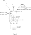
- Figure 3 shows a schematic drawing illustrating a corotating coaxial rotor system 200 modeled with a pair of dissimilar rotors 202, 204.
- Figure 3 is used as a graphical example for describing the following method and it is understood that the method is not limited by Figure 3 .
- the induced power of the lower rotor may be derived according to the following:
- the mass flow through the lower rotor may have two contributions:
- T l ⁇ A l k A ⁇ u + ⁇ l w l ⁇ 2 ⁇ A u ⁇ u 2
- the lower rotor includes two regions.
- the first may be the inner region which lies in the fully developed slipstream of the upper rotor.
- the second may be the outer region which may be unaffected by the upper rotor.
- the individual powers for each of the inner and outer parts may be determined and then summed up.
- an equation for the power per unit thrust of the corotating coaxial system may be determined from the ratio of upper to lower rotor thrusts based on the equality of rotational speeds condition according to the following:
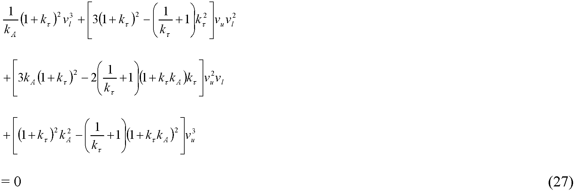
- the cubic equation (27) may be solved for the other induced velocity.
- the specified induced velocity may be determined from the selection of disc loading, which is usually decided upon during the initial stages of the conceptualizing of the corotating coaxial rotor system.
- the selected disc loading may be for the upper rotor, denoted by ( DL ) u .
- the cubic equation (27) may now be solved for the induced velocity of the lower rotor v l .
- the ratio of lower to upper rotor induced velocities may be denoted as k v k ⁇ ⁇ ⁇ l ⁇ u
- the power per unit thrust of the corotating coaxial rotor system may be optimized according to the following:
- the objective of the optimization is to determine the combination of area ratio k A , torque ratio k ⁇ and upper rotor disc loading ( DL ) u which maximizes the hovering efficiency (achieved by minimizing the power per unit thrust P tot / T tot ) as determined by the generalized momentum theory representation of corotating coaxial rotor systems.
- the optimization may be subjected to fulfilling two additional operational requirements:
- Optimization with the quantified operational requirements may be solved by the method of calculus of variations using Lagrange multipliers.
- Two constraint equations may be defined. The first is in relation to the specified thrust and footprint. The second is in relation to the specified k Ttot,spec .
- the equations may be coded and solved numerically in MATLAB ® .
- the equation solver may also be developed in MATLAB ® , and may include
- the developed generalized momentum theory according to an example embodiment is applied in the aerodynamic optimization of the sizing and blade designs of corotating coaxial rotors in conjunction with a calculus of variations, Lagrange multiplier optimization to determine the optimum combination of k A and k ⁇ which achieve a specified total thrust at minimum total induced power of the corotating pair of coaxial rotors, while maintaining equal rotational speeds for the upper and lower rotors.
- the optimization according to the example embodiment using the developed generalized momentum theory is demonstrated in a design example taken from Ref. 2.
- the rotational speed may, for example, be specified for reasons including but not limited to achieving desired rotor tip Mach numbers. e.g. low subsonic Mach numbers for achieving low noise levels.
- the dissimilar rotor diameters and torques resulting from the aerodynamic optimization of the sizing and blade designs of corotating coaxial rotors according to the example embodiment can be used as inputs for the next level of detail: aerodynamic optimization resulting in the details of the geometries of the dissimilar upper and lower rotor blades.
- BEMT Blade Element Momentum Theory
- the method of Ref. 5 contains the following generalizations A) to E):
- the index angle can be chosen to provide additional benefits in aeroacoustics and/or aerodynamics. From an aeroacoustics consideration, corotating rotors inherently do not generate the noise source of pressure impulses of counterrotating rotors when the upper and lower rotor blades cross each other as they rotate in opposite directions, as described in Refs. 6 and 7. Furthermore, the computations of Ref. 8 indicate that, when each of the upper and lower rotors has two blades, index angles in the region of 90° produce destructive interferences between the acoustic waves from the corotating upper and lower rotor blades, which weakens the resulting aerodynamic noise. In consideration of these findings, an index angle of 90° (see numeral 201 in Figure 2 ) is tentatively specified as a geometric parameter according to a nonlimiting example embodiment.
- the resulting corotating pair 200 comprising dissimilar upper and lower rotor blades 202, 204, respectively, is illustrated in Fig. 2 , with the chord distribution, the twist distribution, the pitch angle distribution, and the airfoil distribution etc. for the rotor blades 202, 204 profiles, using the BEMT method according to an example embodiment.
- the lower rotor 204 has a kink 206a, b at the outboard region. This marks the boundary of the downwash from the upper rotor 202 where the downwash contacts with the lower rotor 204.
- this is immersed in the downwash of the upper rotor 202, as illustrated in Fig. 3 , and generates thrust less efficiently due to this interference with the upper rotor.
- the optimizer assigns the inboard region 205 to generate less thrust as compared to the outboard region 207a, b, as a means to reduce the amount of power expended on the inherently less efficient inboard region 205.
- the step change in thrust between the inboard region 205 immersed in the downwash of the upper rotor 202 and the outboard region 207a, b outside of the downwash results in a step change in (optimized) blade chord distribution. Accordingly, the blade profile for the lower rotor 204 contains the kink 206a, b that reflects this step change.
- FM Ideal Power from Generalized Coaxial Momentum Theory Actual Power
- a pre-optimization value of FM using the above definition was determined from experimental measurements of the corotating rotors of Ref 2.
- the FM for the corotating rotors of Ref. 2, as well as the FM after optimization according to the example embodiment of the present invention, are summarized in Table 1.
- the disk loadings are approximately equal, thus allowing for comparisons of FM to be made. It can be seen that in the example embodiment of the present invention, despite negative biasing from operating at lower Reynolds numbers, the optimization is still able to achieve a FM which is substantially higher than in Ref. 2.
- Table 1 Comparison of Figure of Merit (FM) Disk Loading (lb/ft 2 or N/m 2 ) Reynolds Number Upper Rotor Lower Rotor Upper Rotor Lower Rotor FM English Metric English Metric Uehara et al ., 2020 (Ref.
- the index angle may be computed as part of the optimization, rather than being pre-specified.
- aerodynamic considerations may be used in pre-specifying or in optimizing the index angle. For example, Ref. 2 reports that much smaller index angles in the region of 10 0 can yield benefits in additional power loading.
- the number of blades of the upper and lower rotors may be different from two, and/or the upper and lower rotors may have different numbers of blades, e.g upper rotor two blades, lower rotor three blades etc., in different example embodiments
- Figure 4 shows a flowchart 400 illustrating a method of generating a set of values for respective ones of a set of parameters used in determining rotor blade profiles for a corotating coaxial rotor system, according to an example embodiment.
- a ratio of respective desired thrusts of an upper rotor and a lower rotor of the corotating coaxial rotor system is established based on a desired performance of the corotating coaxial rotor system.
- the set of values of the set of parameters is determined from the desired thrusts ratio based on an equal rotation speed condition between the upper rotor and the lower rotor of the corotating coaxial rotor system, wherein the set of parameters includes torques of the upper rotor and the lower rotor.
- the method may comprise establishing a maximum rotor diameter for the corotating coaxial rotor system prior to determining the set of values for the set of parameters and determining the set of values for the set of parameters comprises using the maximum rotor diameter.
- the method may comprise establishing a desired total thrust for the corotating coaxial rotor system prior to determining the set of values for the set of parameters and determining the set of values for the set of parameters comprises using the desired total thrust.
- the method may comprise choosing an index angle of the corotating coaxial rotor system prior to determining the set of values for the set of parameters.
- Determining the set of values for the set of parameters may comprise determining an index angle of the corotating coaxial rotor system.
- Determining the set of values for the set of parameters may comprise optimizing the set of values based on minimizing total induced power for static hover.
- the set of parameters may include a ratio of respective rotor disc areas of the upper rotor and the lower rotor of the corotating coaxial rotor system.
- the set of parameters may include upper rotor diameter and lower rotor diameter.
- the method may comprise assigning an inbound region of the lower rotor from a boundary of downwash from the upper rotor less thrust compared to an outboard region of the lower rotor from the boundary of downwash from the upper rotor.
- the set of parameters include a step change in chord of the lower rotor.
- the ratio of respective desired thrusts of an upper rotor and a lower rotor of the corotating coaxial rotor system may be 1 : 1.
- the torques of the upper rotor and the lower rotor may be included in the set of parameters as a ratio of the torque of the upper rotor and the torque of the lower rotor.
- Figure 5 shows a schematic drawing illustrating a system 500 for generating a set of values for respective ones of a set of parameters used in determining rotor blade profiles for a corotating coaxial rotor system, according to an example embodiment.
- the system 500 comprises means for establishing a ratio of respective desired thrusts, 502, of an upper rotor and a lower rotor of the corotating coaxial rotor system based on a desired performance of the corotating coaxial rotor system; and means for determining the set of values of the set of parameters, 504, from the desired thrusts ratio based on an equal rotation speed condition between the upper rotor and the lower rotor of the corotating coaxial rotor system, wherein the set of parameters includes torques of the upper rotor and the lower rotor.
- the system may comprise means for establishing a maximum rotor diameter, 506, for the corotating coaxial rotor system prior to determining the set of values for the set of parameters and determining the set of values for the set of parameters comprises using the maximum rotor diameter.
- the system may comprise means for establishing a desired total thrust, 508, for the corotating coaxial rotor system prior to determining the set of values for the set of parameters and determining the set of values for the set of parameters comprises using the desired total thrust.
- the system may comprise means for choosing an index angle, 510, of the corotating coaxial rotor system prior to determining the set of values for the set of parameters.
- the means for determining the set of values for the set of parameters, 504, may be configured for determining an index angle of the corotating coaxial rotor system.
- the means for determining the set of values for the set of parameters, 504, may comprise means for optimizing the set of values, 512, based on minimizing total induced power for static hover.
- the set of parameters may include a ratio of respective rotor disc areas of the upper rotor and the lower rotor of the corotating coaxial rotor system.
- the set of parameters may include upper rotor diameter and lower rotor diameter.
- the system may comprise means for assigning, 514, an inbound region of the lower rotor from a boundary of downwash from the upper rotor less thrust compared to an outboard region of the lower rotor from the boundary of downwash from the upper rotor.
- the set of parameters may include a step change in chord of the lower rotor.
- the ratio of respective desired thrusts of an upper rotor and a lower rotor of the corotating coaxial rotor system may be 1 : 1.
- the torques of the upper rotor and the lower rotor may be included in the set of parameters as a ratio of the torque of the upper rotor and the torque of the lower rotor.
- aspects of the systems and methods described herein such as the aerodynamic optimization of the sizing and blade designs of corotating coaxial rotors and the aerodynamic optimization resulting in the details of the geometries of the dissimilar upper and lower rotor blades, for example the means for establishing a ratio of respective desired thrusts, 502, the means for determining the set of values of the set of parameters, 504, the means for establishing a maximum rotor diameter, 506, the means for establishing a desired total thrust, 508, the means for choosing an index angle, 510, the means for optimizing the set of values, 512, and the means for assigning, 514, may be implemented as functionality programmed into any of a variety of circuitry, including programmable logic devices (PLDs), such as field programmable gate arrays (FPGAs), programmable array logic (PAL) devices, electrically programmable logic and memory devices and standard cell-based devices, as well as application specific integrated circuits (ASICs).
- PLDs programmable logic devices
- microcontrollers with memory such as electronically erasable programmable read only memory (EEPROM)
- EEPROM electronically erasable programmable read only memory
- aspects of the system may be embodied in microprocessors having software-based circuit emulation, discrete logic (sequential and combinatorial), custom devices, fuzzy (neural) logic, quantum devices, and hybrids of any of the above device types.
- MOSFET metal-oxide semiconductor field-effect transistor
- CMOS complementary metal-oxide semiconductor
- ECL emitter-coupled logic
- polymer technologies e.g., silicon-conjugated polymer and metal-conjugated polymer-metal structures
- mixed analog and digital etc.
Landscapes
- Engineering & Computer Science (AREA)
- Mechanical Engineering (AREA)
- Aviation & Aerospace Engineering (AREA)
- Physics & Mathematics (AREA)
- Fluid Mechanics (AREA)
- General Physics & Mathematics (AREA)
- Turbine Rotor Nozzle Sealing (AREA)
- Structures Of Non-Positive Displacement Pumps (AREA)
Description
- The present invention relates broadly to aerodynamic optimization of the sizing and blade designs of corotating coaxial rotors.
- Any mention and/or discussion of prior art throughout the specification should not be considered, in any way, as an admission that this prior art is well known or forms part of common general knowledge in the field.
- Aerodynamic optimization of the sizing and blade designs of hovering coaxial rotors can be modelled as a pair of dissimilar actuator discs. For corotating coaxial rotors, i.e. the coaxial rotors rotate in the same rotational direction, rotational speeds of the upper and lower rotors must be the same in order to maintain a fixed index angle (the angle by which the upper rotor azimuthally leads or lags the lower rotor when corotating in the same rotational directions). Experimental studies of such corotating coaxial rotors in Ref. 2 imposed equality of torques for the coaxial rotors.
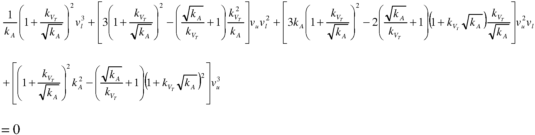
- In previous work Ref. 1 and Ref. 3, a generalized momentum theory for coaxial rotors with dissimilar diameters and rotational speeds, with torques constrained to be equal, derived a cubic equation that relates the induced velocities of the upper and lower rotors, vu and vl , as follows:
- Embodiments of the present invention seek to improve the aerodynamic optimization of the sizing and blade designs of corotating coaxial rotors.
- In accordance with a first aspect of the present invention, there is provided a method of generating a set of values for respective ones of a set of parameters used in determining rotor blade profiles for a corotating coaxial rotor system, the method comprising
- establishing a ratio of respective desired thrusts of an upper rotor and a lower rotor of the corotating coaxial rotor system based on a desired performance of the corotating coaxial rotor system; and
- determining the set of values of the set of parameters from the desired thrusts ratio based on an equal rotation speed condition between the upper rotor and the lower rotor of the corotating coaxial rotor system, wherein the set of parameters includes torques of the upper rotor and the lower rotor.
- In accordance with a second aspect of the present invention, there is provided a system for generating a set of values for respective ones of a set of parameters used in determining rotor blade profiles for a corotating coaxial rotor system, the system comprising:
- means for establishing a ratio of respective desired thrusts of an upper rotor and a lower rotor of the corotating coaxial rotor system based on a desired performance of the corotating coaxial rotor system; and
- means for determining the set of values of the set of parameters from the desired thrusts ratio based on an equal rotation speed condition between the upper rotor and the lower rotor of the corotating coaxial rotor system, wherein the set of parameters includes torques of the upper rotor and the lower rotor.
- Embodiments of the invention will be better understood and readily apparent to one of ordinary skill in the art from the following written description, by way of example only, and in conjunction with the drawings, in which:
-
Figure 1 shows a schematic drawing illustrating optimal dissimilar rotor diameters of a corotating coaxial rotor system resulting from momentum theory optimization according to an example embodiment. -
Figure 2 shows a schematic drawing illustrating aerodynamically optimized corotating dissimilar rotor blade geometries according to an example embodiment. -
Figure 3 shows a schematic drawing illustrating a coaxial actuator discs model with dissimilar diameters for use in an example embodiment. -
Figure 4 shows a flowchart illustrating a method of generating a set of values for respective ones of a set of parameters used in determining rotor blade profiles for a corotating coaxial rotor system, according to an example embodiment. -
Figure 5 shows a schematic drawing illustrating a system for generating a set of values for respective ones of a set of parameters used in determining rotor blade profiles for a corotating coaxial rotor system, according to an example embodiment. - It has been recognized by the present inventor that for aerodynamic optimization of the sizing and blade designs of corotating coaxial rotors, there is no inherent requirement for the upper and lower rotors of a corotating pair of coaxial rotors to have the same torques. Rather, like the diameters of the upper and lower rotors, the torques of the upper and lower rotors can also be different for the aerodynamic optimization.
- More specifically, in an example embodiment a generalized momentum theory has been developed for application in the aerodynamic optimization of the sizing and blade designs of corotating coaxial rotors with fixed index angles by imposing equality of rotational speeds, while lifting the constraint on equality of torques. Details of the generalized momentum theory are described as follows.
-
Figure 3 shows a schematic drawing illustrating a corotatingcoaxial rotor system 200 modeled with a pair ofdissimilar rotors Figure 3 is used as a graphical example for describing the following method and it is understood that the method is not limited byFigure 3 . - According to various embodiments, the set of parameters of the method may include the following ratios:
Ratio of upper to lower rotor disc areas,
- Ratio of upper to lower rotor torques,

- According to various embodiments, by applying the conservation of mass, momentum and energy, the induced power of the upper rotor may be derived according to the following:
Mass flow rate, i.e. the flow of mass through the upper rotor, may be given by:
- Accordingly, the momentum flux exiting the upper rotor may be given by:

- Since the momentum flux exiting the upper rotor may also be equal to the thrust Tu of the upper rotor. Therefore, the thrust of the upper rotor may be expressed as:

- Accordingly, the induced power Pu of the upper rotor may be given by:

- According to various embodiments, by applying the conservation of mass, momentum and energy, the induced power of the lower rotor may be derived according to the following:
The mass flow through the lower rotor may have two contributions: - Mass flow due to the induced velocity vl (= ρAlvl )
- Mass flow passed into the lower rotor from the upper rotor (=ρAuvu )
- Total mass flow through the lower rotor may thus be

- Conservation of momentum may be applied to the lower rotor. The physical statement may be that (Thrust = Momentum flux downstream - Momentum flux upstream). The resulting equation for the thrust Tl of the lower rotor may be

- Expressing the equation for the thrust Tl in terms of kA (ratio of upper to lower rotor disc areas),

- The lower rotor includes two regions. The first may be the inner region which lies in the fully developed slipstream of the upper rotor. The area of this region may be given by:

- The second may be the outer region which may be unaffected by the upper rotor. The area of this region may be given by:

- To determine the induced power of the lower rotor, the individual powers for each of the inner and outer parts may be determined and then summed up.
- The induced power of the inner part of the lower rotor, where thrust = Tl
i , may be given by:
- In order to express Pl
i in terms of area ratio kA and total lower rotor thrust Tl, thrust may be assumed to be weighted by area. This results in
- Substituting back into Eq. (10),

- The induced power of the outer part of the lower rotor, where thrust = Tl
o , may be given by:
- In order to express Pl
o in terms of area ratio kA and total lower rotor thrust Tl, thrust may again be assumed to be weighted by area. This results in
- Substituting back into Eq. (13),

- Summing the contributions of the inner and outer regions, the total induced power of the lower rotor may be given by:

- Accordingly, by substituting from Eqs. (12) and (15), and re-arranging,

- Pl may also be given by the change in kinetic energy from upstream of the lower rotor to far downstream:

- According to various embodiments, the equality of rotational speeds condition may be expressed according to the following:
From Power = Torque x Rotational Speed, the ratio of upper to lower rotor powers may be given by:
- In the equal rotational speeds condition, W l = W u. Hence, the ratio of powers may become

- Substituting using kτ results in the following condition for equality of rotational speeds:

- Substituting from Eqs. (6) and (16), the condition for equality of rotational speeds may be expressed as

- According to various embodiments, a cubic equation which relates to the induced velocities through the upper and lower rotors, vu and vl respectively, may be developed according to the following:
Multiplying Eq. (9) by vu (kAvu + vl ) and re-arranging,
- Substituting the equality of rotational speeds Eq. (20) into the kinetic energy equation for Pl (Eq. (17)) and re-arranging,

- Eq. (23) divided by Eq. (22), and re-arranging,

- Substituting the kinetic energy forms for power, Eqs. (6) and (17), into the equality of rotational speeds Eq. (20),

- After re-arranging,

- Substituting Eq. (24) for wl into Eq. (26), and after considerable re-arrangement, the cubic equation for the developed generalized momentum theory according to an example embodiment becomes
- According to various embodiments, an equation for the power per unit thrust of the corotating coaxial system may be determined from the ratio of upper to lower rotor thrusts based on the equality of rotational speeds condition according to the following:
In general, for a given set of kA, kτ and either of vu or vl , the cubic equation (27) may be solved for the other induced velocity. - The specified induced velocity may be determined from the selection of disc loading, which is usually decided upon during the initial stages of the conceptualizing of the corotating coaxial rotor system. In the present example, the selected disc loading may be for the upper rotor, denoted by (DL) u. The specified induced velocity of the upper rotor may thus be determined from

- The cubic equation (27) may now be solved for the induced velocity of the lower rotor vl.
- The ratio of lower to upper rotor induced velocities may be denoted as kv

- From equality of rotational speeds, Eq. (21), which is reproduced as follows:
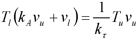
- The ratio of upper to lower rotor thrusts, kT, may be determined as

- The upper rotor thrust, as a fraction of the total corotating coaxial system thrust, may thus be

- The total corotating coaxial system induced power may be given by:

- Substituting the equality of rotational speeds Eq. (20) for Pl,

- Knowing that Pu = Tuvu, and substituting Eqs. (31) and (28), the power per unit thrust of the corotating coaxial rotor system may be determined as follows:

- It should be noted that the Eq. (34) for Ptot / Ttot is a function of three independent variables kA, kτ and (DL) u. These three variables will be the variables in the optimization to be described below, which seeks to minimize Ptot / Ttot , a condition which represents best hovering efficiency.
- According to various embodiments, the power per unit thrust of the corotating coaxial rotor system may be optimized according to the following:
The objective of the optimization is to determine the combination of area ratio kA, torque ratio kτ and upper rotor disc loading (DL) u which maximizes the hovering efficiency (achieved by minimizing the power per unit thrust Ptot / Ttot ) as determined by the generalized momentum theory representation of corotating coaxial rotor systems. - The optimization may be subjected to fulfilling two additional operational requirements:
- Specified amount of thrust to be generated within a specified geometric footprint.
- Specified thrust-sharing percentage between the upper and lower rotors. In the present example embodiment, this has been specified as 50-50 for consistency with Ref. 2. In other embodiments, this may be specified for other reasons including but not limited to: in the scenario that the corotating coaxial rotor system is one of a number of coaxial pairs in a multi-rotor VTOL UAV, safety requirements for recovery from failure of one of the two motors driving the two rotors in a coaxial pair. In this scenario, it is desirable for total thrust to be shared between the upper and lower rotors, such that each rotor is able to compensate for the loss of thrust in the event of failure of the other rotor.
- These operational requirements may be quantified as:
- Specified Ttot,spec (i.e. desired total thrust)
- The footprint is specified through the disc area of the lower rotor, Al,spec (i.e. maximum rotor diameter)
- Specified kTtot,spec
- Optimization with the quantified operational requirements may be solved by the method of calculus of variations using Lagrange multipliers. Two constraint equations may be defined. The first is in relation to the specified thrust and footprint. The second is in relation to the specified kTtot,spec.
- By definition of disc loading,

- Hence, the first constraint equation may be given by:

- The above Eq. (36) may be denoted in terms of a function f1 .

- From the specified thrust ratio,

- Hence, the second constraint equation may be given by:

- The above Eq. (39) may be denoted in terms of a function f2 .

- An auxiliary function H may now be set up as

- There may thus be 5 independent nonlinear equations to be solved for 5 variables: kA, kt, (DL) u, λ1 and λ2 . The 5 equations are:


- The equations may be coded and solved numerically in MATLAB®. The equation solver may also be developed in MATLAB®, and may include
- Genetic Algorithm (GA) technique for initial exploration of the design space, leading to the vicinity of the optimum point; or
- Newton-Raphson technique, initialized using the vicinity point determined by GA, for final convergence, as it is well-known that this technique has very good convergence properties.
- In an example design application, the developed generalized momentum theory according to an example embodiment is applied in the aerodynamic optimization of the sizing and blade designs of corotating coaxial rotors in conjunction with a calculus of variations, Lagrange multiplier optimization to determine the optimum combination of kA and kτ which achieve a specified total thrust at minimum total induced power of the corotating pair of coaxial rotors, while maintaining equal rotational speeds for the upper and lower rotors. The optimization according to the example embodiment using the developed generalized momentum theory is demonstrated in a design example taken from Ref. 2. The objective was to optimize the design of the corotating rotors of Ref. 2 for the intermediate total thrust condition of 366.3N (37.3 kgf or 82.3 lbf), which corresponds to CT /σ = 0.06 for each of the upper and lower rotors in Fig. 5(a) of Ref. 2.
- The versatility of the developed generalized momentum theory for application in the aerodynamic optimization of the sizing and blade designs of corotating coaxial rotors according to the example embodiment, which has no constraints on similar diameters and torques, and which also allows thrust-sharing percentages between the upper and lower rotors to be independently specified (50-50 was used in the example design case, corresponding to kTtot,spec = 0.5, for consistency with Ref. 2), can advantageously handle this design case. The problem statement for this momentum theory optimization example was defined as: To determine the ratios of rotor disc areas kA and torques kτ of the upper and lower rotors of a corotating pair that minimizes total induced power to produce the design total thrust, or Ttot,spec, of 366.3N (37.3 kgf or 82.3 lbf) at static hover, subject to the conditions,
- 1) Equal rotational speeds for the upper and lower rotors (1200rpm from Ref. 2), and
- 2) Maximum geometric footprint for rotor diameter = 2.032m (80in), also from Ref. 2. This corresponded to Al,spec = 3.243m2 (5026.55in2)
- It is noted that 1200rpm was used in the design example for consistency with Ref. (2) as an input to the optimization. In other example embodiments, the rotational speed may, for example, be specified for reasons including but not limited to achieving desired rotor tip Mach numbers. e.g. low subsonic Mach numbers for achieving low noise levels.
- The results which achieved the required total thrust at minimum total induced power were kA = 0.8927 and kτ = 0.6845. The dissimilar pair of rotor disc areas and diameters is illustrated in
Fig. 1 . The key results are summarized as follows: - Optimized minimum total induced power: 2323.6 W (3.12 hp)
- Upper rotor diameter and induced power: 1.920m (75.6in), 944.2 W (1.27 hp)
- Lower rotor diameter and induced power: 2.032m (80in), 1379.4 W (1.85 hp)
- The dissimilar rotor diameters and torques resulting from the aerodynamic optimization of the sizing and blade designs of corotating coaxial rotors according to the example embodiment can be used as inputs for the next level of detail: aerodynamic optimization resulting in the details of the geometries of the dissimilar upper and lower rotor blades. This was done using the Blade Element Momentum Theory (BEMT) method of Ref. 5. Specifically, the method of Ref. 5 contains the following generalizations A) to E):
- A) Allows for dissimilar rotor blade diameters as specified inputs.
However, the BEMT method of Ref. 5 does not size or determine what these parameters should be. According to an example embodiment of the present invention, these parameters were sized beforehand applying the developed generalized momentum theory, and then used as inputs to the BEMT method of Ref. 5. - B) A constraint equation that equates the torques of the upper and lower rotors.
According to an example embodiment of the present invention, this equation is modified to allow for dissimilar rotor torques by applying the factor kτ to the lower rotor torque in a newly developed BEMT method, as expressed by Eq. (47):
i and C P0 are the induced and profile power coefficients, with the superscripts u or l denoting upper or lower rotor respectively. ξR is the ratio of lower to upper rotor radii and ξ Ω is the ratio of upper to lower rotor rotational speeds. - C) Interference inflow to each rotor is more rigorously determined via the Biot-Savart vortex filament model.
- D) Allows the lower rotor to have dissimilar induced inflows for its inner and outer regions.
- E) Thrust distribution over the lower rotor need not be area-weighted over the rotor disc plane.
- The index angle can be chosen to provide additional benefits in aeroacoustics and/or aerodynamics. From an aeroacoustics consideration, corotating rotors inherently do not generate the noise source of pressure impulses of counterrotating rotors when the upper and lower rotor blades cross each other as they rotate in opposite directions, as described in Refs. 6 and 7. Furthermore, the computations of Ref. 8 indicate that, when each of the upper and lower rotors has two blades, index angles in the region of 90° produce destructive interferences between the acoustic waves from the corotating upper and lower rotor blades, which weakens the resulting aerodynamic noise. In consideration of these findings, an index angle of 90° (see numeral 201 in
Figure 2 ) is tentatively specified as a geometric parameter according to a nonlimiting example embodiment. - The resulting
corotating pair 200 comprising dissimilar upper andlower rotor blades Fig. 2 , with the chord distribution, the twist distribution, the pitch angle distribution, and the airfoil distribution etc. for therotor blades - It can be seen in
Fig. 2 that thelower rotor 204 has akink 206a, b at the outboard region. This marks the boundary of the downwash from theupper rotor 202 where the downwash contacts with thelower rotor 204. For theregion 205 inboard of thiskink 206a, b, this is immersed in the downwash of theupper rotor 202, as illustrated inFig. 3 , and generates thrust less efficiently due to this interference with the upper rotor. The optimizer according to the example embodiment assigns theinboard region 205 to generate less thrust as compared to theoutboard region 207a, b, as a means to reduce the amount of power expended on the inherently less efficientinboard region 205. The step change in thrust between theinboard region 205 immersed in the downwash of theupper rotor 202 and theoutboard region 207a, b outside of the downwash results in a step change in (optimized) blade chord distribution. Accordingly, the blade profile for thelower rotor 204 contains thekink 206a, b that reflects this step change. - The hovering efficiency is assessed by defining Figure of Merit (FM) as

- A pre-optimization value of FM using the above definition was determined from experimental measurements of the corotating rotors of Ref 2. As the corotating rotors of Ref. 2 were of equal diameters, rotational speeds and torques, the ideal power can be determined from an earlier momentum theory of Ref. 4, which gives the induced power coefficient as

i is the induced power coefficient of the coaxial pair, CTu and CTl are the thrust coefficients of the upper and lower rotor respectively. - The FM for the corotating rotors of Ref. 2, as well as the FM after optimization according to the example embodiment of the present invention, are summarized in Table 1. The disk loadings are approximately equal, thus allowing for comparisons of FM to be made. It can be seen that in the example embodiment of the present invention, despite negative biasing from operating at lower Reynolds numbers, the optimization is still able to achieve a FM which is substantially higher than in Ref. 2.
Table 1. Comparison of Figure of Merit (FM) Disk Loading (lb/ft2 or N/m2) Reynolds Number Upper Rotor Lower Rotor Upper Rotor Lower Rotor FM English Metric English Metric Uehara et al ., 2020 (Ref. 2) 1.242 59.476 1.117 53.483 490,000 (at 0.75R) 490,000 (at 0.75R) 0.50 Present 1.179 56.434 1.307 62.580 260,000 (Uniform) 180,000 (Uniform for Inner Portion) 0.73 270,000 (Uniform for Outer Portion) - It is noted that in a different example embodiment, the index angle may be computed as part of the optimization, rather than being pre-specified. Also, in a different example embodiment aerodynamic considerations may be used in pre-specifying or in optimizing the index angle. For example, Ref. 2 reports that much smaller index angles in the region of 100 can yield benefits in additional power loading.
- Also, the number of blades of the upper and lower rotors may be different from two, and/or the upper and lower rotors may have different numbers of blades, e.g upper rotor two blades, lower rotor three blades etc., in different example embodiments
-
Figure 4 shows aflowchart 400 illustrating a method of generating a set of values for respective ones of a set of parameters used in determining rotor blade profiles for a corotating coaxial rotor system, according to an example embodiment. Atstep 402, a ratio of respective desired thrusts of an upper rotor and a lower rotor of the corotating coaxial rotor system is established based on a desired performance of the corotating coaxial rotor system. Atstep 404, the set of values of the set of parameters is determined from the desired thrusts ratio based on an equal rotation speed condition between the upper rotor and the lower rotor of the corotating coaxial rotor system, wherein the set of parameters includes torques of the upper rotor and the lower rotor. - The method may comprise establishing a maximum rotor diameter for the corotating coaxial rotor system prior to determining the set of values for the set of parameters and determining the set of values for the set of parameters comprises using the maximum rotor diameter.
- The method may comprise establishing a desired total thrust for the corotating coaxial rotor system prior to determining the set of values for the set of parameters and determining the set of values for the set of parameters comprises using the desired total thrust.
- The method may comprise choosing an index angle of the corotating coaxial rotor system prior to determining the set of values for the set of parameters.
- Determining the set of values for the set of parameters may comprise determining an index angle of the corotating coaxial rotor system.
- Determining the set of values for the set of parameters may comprise optimizing the set of values based on minimizing total induced power for static hover.
- The set of parameters may include a ratio of respective rotor disc areas of the upper rotor and the lower rotor of the corotating coaxial rotor system. The set of parameters may include upper rotor diameter and lower rotor diameter.
- The method may comprise assigning an inbound region of the lower rotor from a boundary of downwash from the upper rotor less thrust compared to an outboard region of the lower rotor from the boundary of downwash from the upper rotor. The set of parameters include a step change in chord of the lower rotor.
- The ratio of respective desired thrusts of an upper rotor and a lower rotor of the corotating coaxial rotor system may be 1 : 1.
- The torques of the upper rotor and the lower rotor may be included in the set of parameters as a ratio of the torque of the upper rotor and the torque of the lower rotor.
-
Figure 5 shows a schematic drawing illustrating asystem 500 for generating a set of values for respective ones of a set of parameters used in determining rotor blade profiles for a corotating coaxial rotor system, according to an example embodiment. Thesystem 500 comprises means for establishing a ratio of respective desired thrusts, 502, of an upper rotor and a lower rotor of the corotating coaxial rotor system based on a desired performance of the corotating coaxial rotor system; and means for determining the set of values of the set of parameters, 504, from the desired thrusts ratio based on an equal rotation speed condition between the upper rotor and the lower rotor of the corotating coaxial rotor system, wherein the set of parameters includes torques of the upper rotor and the lower rotor. - The system may comprise means for establishing a maximum rotor diameter, 506, for the corotating coaxial rotor system prior to determining the set of values for the set of parameters and determining the set of values for the set of parameters comprises using the maximum rotor diameter.
- The system may comprise means for establishing a desired total thrust, 508, for the corotating coaxial rotor system prior to determining the set of values for the set of parameters and determining the set of values for the set of parameters comprises using the desired total thrust.
- The system may comprise means for choosing an index angle, 510, of the corotating coaxial rotor system prior to determining the set of values for the set of parameters.
- The means for determining the set of values for the set of parameters, 504, may be configured for determining an index angle of the corotating coaxial rotor system.
- The means for determining the set of values for the set of parameters, 504, may comprise means for optimizing the set of values, 512, based on minimizing total induced power for static hover. The set of parameters may include a ratio of respective rotor disc areas of the upper rotor and the lower rotor of the corotating coaxial rotor system. The set of parameters may include upper rotor diameter and lower rotor diameter.
- The system may comprise means for assigning, 514, an inbound region of the lower rotor from a boundary of downwash from the upper rotor less thrust compared to an outboard region of the lower rotor from the boundary of downwash from the upper rotor. The set of parameters may include a step change in chord of the lower rotor.
- The ratio of respective desired thrusts of an upper rotor and a lower rotor of the corotating coaxial rotor system may be 1 : 1.
- The torques of the upper rotor and the lower rotor may be included in the set of parameters as a ratio of the torque of the upper rotor and the torque of the lower rotor.
- Aspects of the systems and methods described herein such as the aerodynamic optimization of the sizing and blade designs of corotating coaxial rotors and the aerodynamic optimization resulting in the details of the geometries of the dissimilar upper and lower rotor blades, for example the means for establishing a ratio of respective desired thrusts, 502, the means for determining the set of values of the set of parameters, 504, the means for establishing a maximum rotor diameter, 506, the means for establishing a desired total thrust, 508, the means for choosing an index angle, 510, the means for optimizing the set of values, 512, and the means for assigning, 514, may be implemented as functionality programmed into any of a variety of circuitry, including programmable logic devices (PLDs), such as field programmable gate arrays (FPGAs), programmable array logic (PAL) devices, electrically programmable logic and memory devices and standard cell-based devices, as well as application specific integrated circuits (ASICs). Some other possibilities for implementing aspects of the system include: microcontrollers with memory (such as electronically erasable programmable read only memory (EEPROM)), embedded microprocessors, firmware, software, etc. Furthermore, aspects of the system may be embodied in microprocessors having software-based circuit emulation, discrete logic (sequential and combinatorial), custom devices, fuzzy (neural) logic, quantum devices, and hybrids of any of the above device types. Of course the underlying device technologies may be provided in a variety of component types, e.g., metal-oxide semiconductor field-effect transistor (MOSFET) technologies like complementary metal-oxide semiconductor (CMOS), bipolar technologies like emitter-coupled logic (ECL), polymer technologies (e.g., silicon-conjugated polymer and metal-conjugated polymer-metal structures), mixed analog and digital, etc.
- The systems and methods are not limited by the disclosure, but instead the scope of the systems and methods is to be determined entirely by the claims.
- Unless the context clearly requires otherwise, throughout the description and the claims, the words "comprise," "comprising," and the like are to be construed in an inclusive sense as opposed to an exclusive or exhaustive sense; that is to say, in a sense of "including, but not limited to." Words using the singular or plural number also include the plural or singular number respectively. Additionally, the words "herein," "hereunder," "above," "below," and words of similar import refer to this application as a whole and not to any particular portions of this application. When the word "or" is used in reference to a list of two or more items, that word covers all of the following interpretations of the word: any of the items in the list, all of the items in the list and any combination of the items in the list.
-
- Ref. 1 - Chan, K. I., "Method and System for Generating a Set of Values for Respective Ones of a Set of Parameters Used in Determining Rotor Blade Profiles for a Coaxial Rotor System," International Patent Application Number
PCT/SG2015/050489, December 2015 - Ref. 2 - Uehara, D., Sirohi, J. and Bhagwat, M. J., "Hover Performance of Corotating and Counterrotating Coaxial Rotors," Journal of the American Helicopter Society, Vol. 65, (1), Jan. 2020, pp. 012006. doi: 10.4050/JAHS.65.012006
- Ref. 3 - Chan, K. I., "Generalized Aerodynamic Optimization of Hovering Coaxial Rotor Blades," Journal of the American Helicopter Society, Vol. 64, (2), Apr. 2019, pp. 022006. doi: 1 0.4050/JAHS.64.022006
- Ref. 4 - Leishman, J. G. and Syal, M., "Figure of Merit Definition for Coaxial Rotors," Journal of the American Helicopter Society, Vol. 53, (3), Jul. 2008, pp. 290-300. doi: 10.4050/JAHS.53.290
- Ref. 5 - Rand, O. and Khromov, V., "Aerodynamic Optimization of Coaxial Rotor in Hover and Axial Flight," 27th International Congress of the Aeronautical Sciences, Nice, France, September 19-24, 2010.
- Ref. 6 - Lakshminarayan, V. K. and Baeder, J. D., "High-Resolution Computational Investigation of Trimmed Coaxial Rotor Aerodynamics in Hover," Journal of the American Helicopter Society, Vol. 54, (4), Oct. 2009, pp. 042008. doi: 10.4050/JAHS.54.042008
- Ref. 7 - Schatzman, N. L., "Aerodynamics and Aeroacoustic Sources of a Coaxial Rotor," PhD Thesis, Georgia Institute of Technology, May 2018
- Ref. 8 - Shubham, "Computational Aeroacoustic Investigation of Co-rotating Rotors for Urban Air Mobility," Masters Thesis, Delft University of Technology, Jan. 2020
Claims (15)
- A method of generating a set of values for respective ones of a set of parameters used in determining rotor blade profiles for a corotating coaxial rotor system, the method comprising:establishing a ratio of respective desired thrusts of an upper rotor and a lower rotor of the corotating coaxial rotor system based on a desired performance of the corotating coaxial rotor system; anddetermining the set of values of the set of parameters from the desired thrusts ratio based on an equal rotation speed condition between the upper rotor and the lower rotor of the corotating coaxial rotor system, wherein the set of parameters includes torques of the upper rotor and the lower rotor.
- The method of claim 1, comprising establishing a maximum rotor diameter for the corotating coaxial rotor system prior to determining the set of values for the set of parameters and determining the set of values for the set of parameters comprises using the maximum rotor diameter.
- The method of claims 1 or 2, comprising establishing a desired total thrust for the corotating coaxial rotor system prior to determining the set of values for the set of parameters and determining the set of values for the set of parameters comprises using the desired total thrust.
- The method of any one of claims 1 to 3, comprising choosing an index angle of the corotating coaxial rotor system prior to determining the set of values for the set of parameters; or wherein determining the set of values for the set of parameters comprises determining an index angle of the corotating coaxial rotor system.
- The method of any of claims 1 to 4, wherein determining the set of values for the set of parameters comprises optimizing the set of values based on minimizing total induced power for static hover.
- The method of any of claims 1 to 5, wherein the set of parameters include a ratio of respective rotor disc areas of the upper rotor and the lower rotor of the corotating coaxial rotor system; and optionally wherein the set of parameters include upper rotor diameter and lower rotor diameter.
- The method of any of claims 1 to 6, comprising assigning an inbound region of the lower rotor from a boundary of downwash from the upper rotor less thrust compared to an outboard region of the lower rotor from the boundary of downwash from the upper rotor; and optionally wherein the set of parameters include a step change in chord of the lower rotor.
- The method of any of claims 1 to 7, wherein the ratio of respective desired thrusts of an upper rotor and a lower rotor of the corotating coaxial rotor system is 1 : 1; and/or wherein the torques of the upper rotor and the lower rotor are included in the set of parameters as a ratio of the torque of the upper rotor and the torque of the lower rotor.
- A system for generating a set of values for respective ones of a set of parameters used in determining rotor blade profiles for a corotating coaxial rotor system, the system comprising:means for establishing a ratio of respective desired thrusts of an upper rotor and a lower rotor of the corotating coaxial rotor system based on a desired performance of the corotating coaxial rotor system; andmeans for determining the set of values of the set of parameters from the desired thrusts ratio based on an equal rotation speed condition between the upper rotor and the lower rotor of the corotating coaxial rotor system, wherein the set of parameters includes torques of the upper rotor and the lower rotor.
- The system of claim 9, comprising means for establishing a maximum rotor diameter for the corotating coaxial rotor system prior to determining the set of values for the set of parameters and determining the set of values for the set of parameters comprises using the maximum rotor diameter; and/or comprising means for establishing a desired total thrust for the corotating coaxial rotor system prior to determining the set of values for the set of parameters and determining the set of values for the set of parameters comprises using the desired total thrust.
- The system of any one of claims 9 to 10, comprising means for choosing an index angle of the corotating coaxial rotor system prior to determining the set of values for the set of parameters; or wherein the means for determining the set of values for the set of parameters is configured for determining an index angle of the corotating coaxial rotor system.
- The system of any of claims 9 to 11, wherein the means for determining the set of values for the set of parameters comprises means for optimizing the set of values based on minimizing total induced power for static hover.
- The system of any of claims 9 to 12, wherein the set of parameters include a ratio of respective rotor disc areas of the upper rotor and the lower rotor of the corotating coaxial rotor system; and optionally wherein the set of parameters include upper rotor diameter and lower rotor diameter.
- The system of any of claims 9 to 13, comprising means for assigning an inbound region of the lower rotor from a boundary of downwash from the upper rotor less thrust compared to an outboard region of the lower rotor from the boundary of downwash from the upper rotor; and optionally wherein the set of parameters include a step change in chord of the lower rotor.
- The system of any of claims 9 to 14, wherein the ratio of respective desired thrusts of an upper rotor and a lower rotor of the corotating coaxial rotor system is 1 : 1, and/or wherein the torques of the upper rotor and the lower rotor are included in the set of parameters as a ratio of the torque of the upper rotor and the torque of the lower rotor.
Applications Claiming Priority (2)
| Application Number | Priority Date | Filing Date | Title |
|---|---|---|---|
| SG10202010770P | 2020-10-29 | ||
| PCT/SG2020/050745 WO2022093109A1 (en) | 2020-10-29 | 2020-12-14 | Aerodynamic optimization of the sizing and blade designs of corotating coaxial rotors |
Publications (4)
| Publication Number | Publication Date |
|---|---|
| EP4237328A1 EP4237328A1 (en) | 2023-09-06 |
| EP4237328A4 EP4237328A4 (en) | 2024-03-13 |
| EP4237328B1 true EP4237328B1 (en) | 2025-02-12 |
| EP4237328C0 EP4237328C0 (en) | 2025-02-12 |
Family
ID=81384485
Family Applications (1)
| Application Number | Title | Priority Date | Filing Date |
|---|---|---|---|
| EP20926359.9A Active EP4237328B1 (en) | 2020-10-29 | 2020-12-14 | Aerodynamic optimization of the sizing and blade designs of corotating coaxial rotors |
Country Status (3)
| Country | Link |
|---|---|
| US (1) | US20230084519A1 (en) |
| EP (1) | EP4237328B1 (en) |
| WO (1) | WO2022093109A1 (en) |
Families Citing this family (1)
| Publication number | Priority date | Publication date | Assignee | Title |
|---|---|---|---|---|
| CN120105756B (en) * | 2025-05-08 | 2025-09-09 | 大连理工大学 | A modeling method for helicopter blades with complex configuration based on multi-body dynamics |
Family Cites Families (6)
| Publication number | Priority date | Publication date | Assignee | Title |
|---|---|---|---|---|
| WO2010134924A1 (en) * | 2009-05-22 | 2010-11-25 | Bell Helicopter Textron Inc. | Co-rotating stacked rotor disks for improved hover performance |
| US10112707B1 (en) * | 2014-10-03 | 2018-10-30 | John V. Howard | Remotely controlled co-axial rotorcraft for heavy-lift aerial-crane operations |
| US20180281949A1 (en) * | 2015-09-09 | 2018-10-04 | Altus IP Limited | Systems and methods for stabilisation of aerial vehicles |
| CN108698688B (en) * | 2015-12-09 | 2022-06-07 | 新科宇航 | Method and system for generating a set of values for determining a respective parameter of a set of parameters of a rotor blade profile of an in-line rotor system |
| CN108463406A (en) * | 2016-09-09 | 2018-08-28 | 深圳市大疆创新科技有限公司 | A kind of propeller component, dynamical system and aircraft |
| US10752352B2 (en) * | 2017-12-07 | 2020-08-25 | Textron Innovations Inc. | Dual rotor propulsion systems for tiltrotor aircraft |
-
2020
- 2020-12-14 WO PCT/SG2020/050745 patent/WO2022093109A1/en not_active Ceased
- 2020-12-14 US US17/800,192 patent/US20230084519A1/en active Pending
- 2020-12-14 EP EP20926359.9A patent/EP4237328B1/en active Active
Also Published As
| Publication number | Publication date |
|---|---|
| EP4237328C0 (en) | 2025-02-12 |
| US20230084519A1 (en) | 2023-03-16 |
| WO2022093109A1 (en) | 2022-05-05 |
| EP4237328A4 (en) | 2024-03-13 |
| EP4237328A1 (en) | 2023-09-06 |
Similar Documents
| Publication | Publication Date | Title |
|---|---|---|
| US20210253236A1 (en) | Rotary airfoil and design therefore | |
| Tung et al. | The prediction of transonic flows on an advancing rotor | |
| Griffiths et al. | Predictions of rotor performance in ground effect using a free‐vortex wake model | |
| Ventura Diaz et al. | The side-by-side urban air taxi concept | |
| Ventura Diaz et al. | Simulations of ducted and coaxial rotors for air taxi operations | |
| Healy et al. | A CFD-based examination of rotor-rotor separation effects on interactional aerodynamics for eVTOL aircraft | |
| US20230084519A1 (en) | Aerodynamic optimization of the sizing and blade designs of corotating coaxial rotors | |
| Wang et al. | Approximately arc-length parametrized C3 quintic interpolatory splines | |
| Jimenez et al. | Effect of duct-rotor aerodynamic interactions on blade design for hover and axial flight | |
| US11014662B2 (en) | Method and system for generating a set of values for respective ones of a set of parameters used in determining rotor blade profiles for a coaxial rotor system | |
| Opazo et al. | Analytical and experimental power minimization for fixed-pitch coaxial rotors in hover | |
| Kallstrom et al. | Airfoil table generation and validation for the vr-12 and ssc-a09 airfoils and quadrotor performance prediction | |
| Lee et al. | Aerodynamic characteristic analysis of multi-rotors using a modified free-wake method | |
| Dangelo | Wide speed range turboshaft study | |
| Gur et al. | Prop-rotor design for an electric tilt-rotor vehicle | |
| Hassan et al. | Airfoil design for helicopter rotor blades-a three-dimensional approach | |
| DiPalma et al. | Optimization of extension-twist coupled composite blades for high-speed rotorcraft | |
| Chan | Aerodynamic optimization of the sizing and blade designs of hovering corotating coaxial rotors | |
| Dayhoum et al. | Aerodynamic Investigation of Shrouded Rotors with Dual Exit Channels | |
| Chung et al. | Numerical predictions of rotorcraft unsteady air-loadings and BVI noise by using a time-marching free-wake and acoustic analogy | |
| SUMMA | Potential flow about three-dimensional lifting configurations, with application to wings and rotors | |
| Mehr et al. | DuctAPE: a steady-state, axisymmetric ducted fan analysis code designed for gradient-based optimization | |
| McCune et al. | Lifting-line theory for subsonic axial compressor rotors | |
| Hong et al. | A dynamic-inflow-based induced power model for general and optimal rotor performance | |
| Tsung et al. | Numerical simulation of flow separation for rotors and fixed wings |
Legal Events
| Date | Code | Title | Description |
|---|---|---|---|
| STAA | Information on the status of an ep patent application or granted ep patent |
Free format text: STATUS: UNKNOWN |
|
| STAA | Information on the status of an ep patent application or granted ep patent |
Free format text: STATUS: THE INTERNATIONAL PUBLICATION HAS BEEN MADE |
|
| PUAI | Public reference made under article 153(3) epc to a published international application that has entered the european phase |
Free format text: ORIGINAL CODE: 0009012 |
|
| STAA | Information on the status of an ep patent application or granted ep patent |
Free format text: STATUS: REQUEST FOR EXAMINATION WAS MADE |
|
| 17P | Request for examination filed |
Effective date: 20210928 |
|
| AK | Designated contracting states |
Kind code of ref document: A1 Designated state(s): AL AT BE BG CH CY CZ DE DK EE ES FI FR GB GR HR HU IE IS IT LI LT LU LV MC MK MT NL NO PL PT RO RS SE SI SK SM TR |
|
| DAV | Request for validation of the european patent (deleted) | ||
| DAX | Request for extension of the european patent (deleted) | ||
| A4 | Supplementary search report drawn up and despatched |
Effective date: 20240212 |
|
| RIC1 | Information provided on ipc code assigned before grant |
Ipc: B64C 27/467 20060101ALI20240206BHEP Ipc: B64C 27/10 20230101AFI20240206BHEP |
|
| GRAP | Despatch of communication of intention to grant a patent |
Free format text: ORIGINAL CODE: EPIDOSNIGR1 |
|
| STAA | Information on the status of an ep patent application or granted ep patent |
Free format text: STATUS: GRANT OF PATENT IS INTENDED |
|
| INTG | Intention to grant announced |
Effective date: 20240829 |
|
| GRAS | Grant fee paid |
Free format text: ORIGINAL CODE: EPIDOSNIGR3 |
|
| GRAA | (expected) grant |
Free format text: ORIGINAL CODE: 0009210 |
|
| STAA | Information on the status of an ep patent application or granted ep patent |
Free format text: STATUS: THE PATENT HAS BEEN GRANTED |
|
| AK | Designated contracting states |
Kind code of ref document: B1 Designated state(s): AL AT BE BG CH CY CZ DE DK EE ES FI FR GB GR HR HU IE IS IT LI LT LU LV MC MK MT NL NO PL PT RO RS SE SI SK SM TR |
|
| REG | Reference to a national code |
Ref country code: GB Ref legal event code: FG4D |
|
| REG | Reference to a national code |
Ref country code: CH Ref legal event code: EP |
|
| REG | Reference to a national code |
Ref country code: DE Ref legal event code: R096 Ref document number: 602020046156 Country of ref document: DE |
|
| REG | Reference to a national code |
Ref country code: IE Ref legal event code: FG4D |
|
| U01 | Request for unitary effect filed |
Effective date: 20250307 |
|
| U07 | Unitary effect registered |
Designated state(s): AT BE BG DE DK EE FI FR IT LT LU LV MT NL PT RO SE SI Effective date: 20250314 |
|
| PG25 | Lapsed in a contracting state [announced via postgrant information from national office to epo] |
Ref country code: RS Free format text: LAPSE BECAUSE OF FAILURE TO SUBMIT A TRANSLATION OF THE DESCRIPTION OR TO PAY THE FEE WITHIN THE PRESCRIBED TIME-LIMIT Effective date: 20250512 |
|
| PG25 | Lapsed in a contracting state [announced via postgrant information from national office to epo] |
Ref country code: PL Free format text: LAPSE BECAUSE OF FAILURE TO SUBMIT A TRANSLATION OF THE DESCRIPTION OR TO PAY THE FEE WITHIN THE PRESCRIBED TIME-LIMIT Effective date: 20250212 |
|
| PG25 | Lapsed in a contracting state [announced via postgrant information from national office to epo] |
Ref country code: ES Free format text: LAPSE BECAUSE OF FAILURE TO SUBMIT A TRANSLATION OF THE DESCRIPTION OR TO PAY THE FEE WITHIN THE PRESCRIBED TIME-LIMIT Effective date: 20250212 |
|
| PG25 | Lapsed in a contracting state [announced via postgrant information from national office to epo] |
Ref country code: IS Free format text: LAPSE BECAUSE OF FAILURE TO SUBMIT A TRANSLATION OF THE DESCRIPTION OR TO PAY THE FEE WITHIN THE PRESCRIBED TIME-LIMIT Effective date: 20250612 Ref country code: NO Free format text: LAPSE BECAUSE OF FAILURE TO SUBMIT A TRANSLATION OF THE DESCRIPTION OR TO PAY THE FEE WITHIN THE PRESCRIBED TIME-LIMIT Effective date: 20250512 |
|
| PG25 | Lapsed in a contracting state [announced via postgrant information from national office to epo] |
Ref country code: HR Free format text: LAPSE BECAUSE OF FAILURE TO SUBMIT A TRANSLATION OF THE DESCRIPTION OR TO PAY THE FEE WITHIN THE PRESCRIBED TIME-LIMIT Effective date: 20250212 |
|
| PG25 | Lapsed in a contracting state [announced via postgrant information from national office to epo] |
Ref country code: GR Free format text: LAPSE BECAUSE OF FAILURE TO SUBMIT A TRANSLATION OF THE DESCRIPTION OR TO PAY THE FEE WITHIN THE PRESCRIBED TIME-LIMIT Effective date: 20250513 |
|
| PG25 | Lapsed in a contracting state [announced via postgrant information from national office to epo] |
Ref country code: SM Free format text: LAPSE BECAUSE OF FAILURE TO SUBMIT A TRANSLATION OF THE DESCRIPTION OR TO PAY THE FEE WITHIN THE PRESCRIBED TIME-LIMIT Effective date: 20250212 |
|
| PG25 | Lapsed in a contracting state [announced via postgrant information from national office to epo] |
Ref country code: CZ Free format text: LAPSE BECAUSE OF FAILURE TO SUBMIT A TRANSLATION OF THE DESCRIPTION OR TO PAY THE FEE WITHIN THE PRESCRIBED TIME-LIMIT Effective date: 20250212 |
|
| PG25 | Lapsed in a contracting state [announced via postgrant information from national office to epo] |
Ref country code: SK Free format text: LAPSE BECAUSE OF FAILURE TO SUBMIT A TRANSLATION OF THE DESCRIPTION OR TO PAY THE FEE WITHIN THE PRESCRIBED TIME-LIMIT Effective date: 20250212 |
|
| PLBE | No opposition filed within time limit |
Free format text: ORIGINAL CODE: 0009261 |
|
| STAA | Information on the status of an ep patent application or granted ep patent |
Free format text: STATUS: NO OPPOSITION FILED WITHIN TIME LIMIT |
|
| PGFP | Annual fee paid to national office [announced via postgrant information from national office to epo] |
Ref country code: GB Payment date: 20251218 Year of fee payment: 6 |
|
| U20 | Renewal fee for the european patent with unitary effect paid |
Year of fee payment: 6 Effective date: 20251210 |
|
| 26N | No opposition filed |
Effective date: 20251113 |