EP4236489A1 - Verfahren und vorrichtung zur steuerung der funkemissionen einer basisstation - Google Patents
Verfahren und vorrichtung zur steuerung der funkemissionen einer basisstation Download PDFInfo
- Publication number
- EP4236489A1 EP4236489A1 EP23153613.7A EP23153613A EP4236489A1 EP 4236489 A1 EP4236489 A1 EP 4236489A1 EP 23153613 A EP23153613 A EP 23153613A EP 4236489 A1 EP4236489 A1 EP 4236489A1
- Authority
- EP
- European Patent Office
- Prior art keywords
- power reduction
- radio emissions
- time
- time window
- radio
- Prior art date
- Legal status (The legal status is an assumption and is not a legal conclusion. Google has not performed a legal analysis and makes no representation as to the accuracy of the status listed.)
- Pending
Links
Images


Classifications
-
- H—ELECTRICITY
- H04—ELECTRIC COMMUNICATION TECHNIQUE
- H04W—WIRELESS COMMUNICATION NETWORKS
- H04W52/00—Power management, e.g. Transmission Power Control [TPC] or power classes
- H04W52/04—Transmission power control [TPC]
- H04W52/30—Transmission power control [TPC] using constraints in the total amount of available transmission power
- H04W52/36—Transmission power control [TPC] using constraints in the total amount of available transmission power with a discrete range or set of values, e.g. step size, ramping or offsets
- H04W52/362—Aspects of the step size
-
- H—ELECTRICITY
- H04—ELECTRIC COMMUNICATION TECHNIQUE
- H04W—WIRELESS COMMUNICATION NETWORKS
- H04W52/00—Power management, e.g. Transmission Power Control [TPC] or power classes
- H04W52/04—Transmission power control [TPC]
- H04W52/18—TPC being performed according to specific parameters
- H04W52/22—TPC being performed according to specific parameters taking into account previous information or commands
-
- H—ELECTRICITY
- H04—ELECTRIC COMMUNICATION TECHNIQUE
- H04B—TRANSMISSION
- H04B17/00—Monitoring; Testing
- H04B17/30—Monitoring; Testing of propagation channels
- H04B17/391—Modelling the propagation channel
- H04B17/3913—Predictive models, e.g. based on neural network models
-
- H—ELECTRICITY
- H04—ELECTRIC COMMUNICATION TECHNIQUE
- H04W—WIRELESS COMMUNICATION NETWORKS
- H04W52/00—Power management, e.g. Transmission Power Control [TPC] or power classes
- H04W52/04—Transmission power control [TPC]
- H04W52/06—TPC algorithms
- H04W52/14—Separate analysis of uplink or downlink
- H04W52/143—Downlink power control
-
- H—ELECTRICITY
- H04—ELECTRIC COMMUNICATION TECHNIQUE
- H04W—WIRELESS COMMUNICATION NETWORKS
- H04W52/00—Power management, e.g. Transmission Power Control [TPC] or power classes
- H04W52/04—Transmission power control [TPC]
- H04W52/30—Transmission power control [TPC] using constraints in the total amount of available transmission power
- H04W52/36—Transmission power control [TPC] using constraints in the total amount of available transmission power with a discrete range or set of values, e.g. step size, ramping or offsets
- H04W52/367—Power values between minimum and maximum limits, e.g. dynamic range
-
- H—ELECTRICITY
- H04—ELECTRIC COMMUNICATION TECHNIQUE
- H04W—WIRELESS COMMUNICATION NETWORKS
- H04W52/00—Power management, e.g. Transmission Power Control [TPC] or power classes
- H04W52/04—Transmission power control [TPC]
- H04W52/18—TPC being performed according to specific parameters
- H04W52/22—TPC being performed according to specific parameters taking into account previous information or commands
- H04W52/223—TPC being performed according to specific parameters taking into account previous information or commands predicting future states of the transmission
-
- H—ELECTRICITY
- H04—ELECTRIC COMMUNICATION TECHNIQUE
- H04W—WIRELESS COMMUNICATION NETWORKS
- H04W52/00—Power management, e.g. Transmission Power Control [TPC] or power classes
- H04W52/04—Transmission power control [TPC]
- H04W52/18—TPC being performed according to specific parameters
- H04W52/22—TPC being performed according to specific parameters taking into account previous information or commands
- H04W52/226—TPC being performed according to specific parameters taking into account previous information or commands using past references to control power, e.g. look-up-table
-
- H—ELECTRICITY
- H04—ELECTRIC COMMUNICATION TECHNIQUE
- H04W—WIRELESS COMMUNICATION NETWORKS
- H04W52/00—Power management, e.g. Transmission Power Control [TPC] or power classes
- H04W52/04—Transmission power control [TPC]
- H04W52/18—TPC being performed according to specific parameters
- H04W52/22—TPC being performed according to specific parameters taking into account previous information or commands
- H04W52/228—TPC being performed according to specific parameters taking into account previous information or commands using past power values or information
Definitions
- Various example embodiments relate generally to methods and apparatus for controlling radio emissions of a base station, including computing a power reduction policy and implementing the power reduction policy at the base station to control the radio emissions of the base station.
- RAN Radio Access Network
- 5G fifth generation
- 5G NR New Radio
- RAT radio access technology
- 5G uses advanced antenna technologies and new allocated frequency bands. Regulations have been established setting limits to human exposure to radio frequency emissions. These limits must be met by radio equipment whatever the radio technology, particularly radio base stations in the radio access networks.
- ICNIRP international guidelines like ICNIRP specify maximum exposure levels to be met over time windows of 6 or 30 minutes.
- national regulations may also apply. Some of them specify limits over much longer time windows.
- Italian regulation specifies maximum exposure levels to be met over a time window of 24 hours.
- an apparatus for computing a power reduction policy to control radio emissions of a base station over a time window subdivided into a plurality of time periods starting at a plurality of time steps, the apparatus comprising means for, at least at a first time step in the time window:
- a method for computing a power reduction policy to control radio emissions of a base station over a time window subdivided into a plurality of time periods starting at a plurality of time steps, the method comprising, at least at a first time step in the time window:
- generating the prediction of averaged radio emissions over subsequent time periods in the time window is further based on an average of radio emissions measured over the previous time period in the time window.
- the cost function is based on:
- finding couples of values of a power reduction factor and average of radio emissions that minimize a cost function for a given time step in the time window comprises, for each given average of radio emissions in a set of possible values of average of radio emissions:
- the method for computing a power reduction policy comprises sending the power reduction policy to the base station.
- a base station comprising means for obtaining a power reduction policy from an apparatus as disclosed above and means for implementing the power reduction policy during a given time period starting at a given time step based on the radio emissions averaged over the time window at the given time step.
- the disclosed base station further comprises an apparatus as disclosed above for computing a power reduction policy.
- implementing the power reduction policy comprises:
- implementing the power reduction policy comprises:
- a central entity for use in a radio access network comprising at least one base station, the central entity comprising an apparatus as disclosed above for computing a power reduction policy and means for sending the power reduction policy to the base station.
- the central entity and the method for computing a power reduction policy comprise means for collecting the radio emissions historical data from all base stations in the radio access network.
- a computer program product comprising a set of instructions which, when executed on an apparatus, is configured to cause the apparatus, the base station or the central entity to carry out a method as disclosed herein.
- the means referred to above in relation to the apparatus, the base station and the central entity include circuitry configured to perform one or more or all steps of the method for computing the power reduction policy and the method for controlling radio emissions of a radio base station based on the computed power reduction policy.
- the means may include at least one processor and at least one memory including computer program code, wherein the at least one memory and the computer program code are configured to, with the at least one processor, cause the apparatus, the base station or the central entity to perform one or more or all steps of the methods disclosed herein.
- EIRP Equivalent Isotropic Radiated Power - which combines power and gain
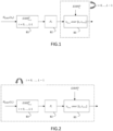
- FIG.1 and FIG.2 show two variants of a method for controlling radio emissions.
- a power reduction policy is computed to control the average EIRP of a base station over a time window [0, T].
- the time window may have a length of 24 hours and the time periods may have a length of 3 or 6 hours each.
- the method comprises a prediction block B1, a policy computation block B2 and a power reduction block B3.
- the policy computation block B2 computes a power reduction policy P that maps average EIRP values with values of power reduction factors for each time step t i in the time window.
- the power reduction block B3 obtains the power reduction policy P. For a given time step t i , block B3 retrieves from policy P the power reduction factor r t i +1 which corresponds to the measured average EIRP t i m at time t i . Block B3 controls the actual EIRP during the time period [ t i , t i +1 ] based on the retrieved power reduction factor r t i +1 .
- the prediction at block B1 and the computation of the power reduction policy at block B2 are performed only at the beginning of the time window, that is at the first time step t 0 .
- FIG.3 is an exemplary implementation of a method for controlling radio emissions in a radio access network 30 comprising a central entity 31 and a plurality of base stations 32.
- the central entity can be a RIC (Radio Intelligent Controller) or a CSON entity (Central Self Organizing Network).
- blocks B1 and B2 are implemented in the central entity 31 whereas block B3 is implemented in the base stations 32.
- the central entity 31 requests EIRP measurements to the base stations 32.
- the base stations 32 respond by sending their EIRP historical data.
- the central entity 31 performs the EIRP prediction of block B1.
- the central entity 31 performs the policy computation of block B2.
- the central entity 31 sends the power reduction policy P obtained at step 36 to the base stations 32.
- the base stations 32 perform the power reduction of block B3 based on the received power reduction policy P.
- historical data H EIRP ( t i ) sent by the base stations 32 at time step t i includes:
- the central entity 31 receives EIRP historical data from a plurality of base stations in the radio access network which improves the prediction and the performance of the power reduction policy.
- a significant quantity of data needs to be transmitted between the central entity 31 and the base stations 32. This can be mitigated by reducing the frequency at which the power reduction policy is recomputed by the central entity 31 or, when the policy is recomputed at each time step, by increasing the duration of the time periods.
- the central entity when the central entity is a RIC, data are transmitted between the central entity 31 and the base stations 32 over an E2 interface.
- all three blocks B1, B2, B3 may be implemented in the base stations.
- the base stations perform block B1 prediction based on their own historical data only.
- the EIRP prediction of block B1 may be performed by using prediction techniques known in the art, for example linear regression or neural network-based prediction.
- the objective of the power reduction policy is to keep the average EIRP over the time window [0, T] below an authorized value M T set in the regulations, with minimum impact on the performance of the overall system.
- the power reduction policy maps average EIRP values with values of power reduction factors for each time step t i in the time window.
- the above objective is achieved by finding, for each time step t i in the time window, couples of values ⁇ r t i , EIRP t i ⁇ of power reduction factors and average EIRP that minimize a cost function C.
- the policy shall avoid overshooting with EIRP t i ( r t i ) values too low from the authorized value M T . It shall also avoid enforcing high power reduction factor at all time.
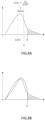
- the cost function C is based on two auxiliary functions h and g.
- the first auxiliary function h applies to the average EIRP and is defined to penalize more radio emissions that are farther from an authorized value M T .
- the second auxiliary function g applies to the power reduction factor and is defined to penalize high power reduction factors and to smooth out the power reduction factors over time.
- FIG.4A gives an example of a first auxiliary function h and FIG.4B gives an example of a second auxiliary function g .
- the power reduction policy can be computed by using a mathematical optimization method, for example dynamic programming as will be described in more details below by reference to FIG.5 .
- EIRP t i ( r t i ) denotes the reduced EIRP at time step t i obtained by applying the power reduction factor r t i , retrieved from the power reduction policy, to the EIRP averaged over the time period [ t i , t i +1 ]:
- EIRP t i r t i EIRP t i r t i .
- the objective is to find the couples of values ⁇ r , s ⁇ , r ⁇ R , s ⁇ S that minimize the cost function C for a given time step Q in the time window.
- the power reduction factor r k ( s ) argmin ⁇ C k ( s ) ⁇ is calculated.
- the value r k ( s ) is the value that minimize the cost function C k ( s ) .
- the final value r Q ( s ) is output and stored in association with the corresponding value s of weighted average EIRP.
- the resulting policy P can be stored in a table which comprises for each value of Q (that is for each time step t Q ), couples of values ⁇ r , s ⁇ that minimize the cost function C.
- FIG.6 gives an example of a power reduction policy obtained with the method described above.
- the policy is depicted for time steps t 0 , ..., t 3 .
- block B3 controls the actual EIRP during the time period [ t i , t i +1 ] based on the retrieved power reduction factor r t i +1 .
- the actual EIRP is controlled by applying the retrieved power reduction factor directly during the entire duration of the time period [ t i , t i +1 ]. In practice this may be achieved by reducing utilization of the Physical Resource Block (PBR) by the constant factor r t i +1 during the whole time period [ t i , t i +1 ]. Reducing the PBR means that transmission is only allowed for a portion 1/r t i +1 of the available PBRs while the remaining PBRs are blanked out.
- PBR Physical Resource Block
- a second embodiment is based on the solution described in WO2021/023375 which controls the actual EIRP values exceeding an EIRP constraint ⁇ i +1 over the time period [ t i , t i +1 ].
- the constraint ⁇ i +1 needs first to be obtained from the power reduction factor r t i +1 .
- FIG.7 shows a detailed representation of block B3 with this second approach.
- the power reduction factor r t i +1 is retrieved from the policy, based on the value of the EIRP averaged during [ t 0 , t i ] .
- F i ( ⁇ i ) is referred to as equivalent EIRP reduction factor.
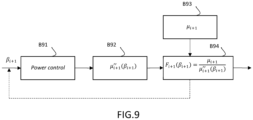
- FIG.9 is a block diagram illustrating the offline learning of the equivalent EIRP reduction factor F i +1 ( ⁇ i +1 ).
- power control is applied based on the constraint ⁇ i +1 .
- the average EIRP over the time period [ t i , t i +1 ] denoted ⁇ i + 1 " ⁇ i + 1 is computed.
- FIG. 10 depicts a high-level block diagram of an apparatus 100 suitable for implementing various aspects of the disclosure. Although illustrated in a single block, in other embodiments the apparatus 100 may also be implemented using parallel and distributed architectures. Thus, for example, various steps such as those illustrated in the system and methods described above by reference to FIG.1 to 9 may be executed using apparatus 100 sequentially, in parallel, or in a different order based on particular implementations.
- apparatus 100 comprises a printed circuit board 101 on which a communication bus 102 connects a processor 103 (e.g., a central processing unit "CPU"), a random access memory 104, a storage medium 111, an interface 105 for connecting a display 106, a series of connectors 107 for connecting user interface devices or modules such as a mouse or trackpad 108 and a keyboard 109, a wireless network interface 110 and a wired network interface 112.
- processor 103 e.g., a central processing unit "CPU”
- random access memory 104 e.g., a central processing unit "CPU”
- storage medium 111 e.g., a central processing unit "CPU”
- an interface 105 for connecting a display 106
- a series of connectors 107 for connecting user interface devices or modules
- user interface devices or modules such as a mouse or trackpad 108 and a keyboard 109
- wireless network interface 110 e.g., a wireless network interface
- display 106 may be a display that is connected to the apparatus only under specific circumstances, or the apparatus may be controlled through another device with a display, i.e. no specific display 106 and interface 105 are required for such an apparatus.
- Memory 111 contains software code which, when executed by processor 103, causes the apparatus 100 to perform the methods described herein.
- Storage medium 113 is a detachable device such as a USB stick which holds the software code which can be uploaded to memory 111.
- the processor 603 may be any type of processor such as a general purpose central processing unit (“CPU") or a dedicated microprocessor such as an embedded microcontroller or a digital signal processor (“DSP").
- CPU general purpose central processing unit
- DSP digital signal processor
- apparatus 100 may also include other components typically found in computing systems, such as an operating system, queue managers, device drivers, or one or more network protocols that are stored in memory 111 and executed by the processor 103.
- the data disclosed herein may be stored in various types of data structures which may be accessed and manipulated by a programmable processor (e.g., CPU or FPGA) that is implemented using software, hardware, or combination thereof.
- a programmable processor e.g., CPU or FPGA
- Each described function, engine, block, step can be implemented in hardware, software, firmware, middleware, microcode, or any suitable combination thereof. If implemented in software, the functions, engines, blocks of the block diagrams and/or flowchart illustrations can be implemented by computer program instructions / software code, which may be stored or transmitted over a computer-readable medium, or loaded onto a general purpose computer, special purpose computer or other programmable processing apparatus and / or system to produce a machine, such that the computer program instructions or software code which execute on the computer or other programmable processing apparatus, create the means for implementing the functions described herein.
- block denoted as "means configured to perform " (a certain function) shall be understood as functional blocks comprising circuitry that is adapted for performing or configured to perform a certain function.
- a means being configured to perform a certain function does, hence, not imply that such means necessarily is performing said function (at a given time instant).
- any entity described herein as “means” may correspond to or be implemented as “one or more modules", “one or more devices”, “one or more units”, etc.
- the functions may be provided by a single dedicated processor, by a single shared processor, or by a plurality of individual processors, some of which may be shared.
- processor or “controller” should not be construed to refer exclusively to hardware capable of executing software, and may implicitly include, without limitation, digital signal processor (DSP) hardware, network processor, application specific integrated circuit (ASIC), field programmable gate array (FPGA), read only memory (ROM) for storing software, random access memory (RAM), and non-volatile storage.
- DSP digital signal processor
- ASIC application specific integrated circuit
- FPGA field programmable gate array
- ROM read only memory
- RAM random access memory
- non-volatile storage non-volatile storage.
- Other hardware conventional or custom, may also be included. Their function may be carried out through the operation of program logic, through dedicated logic, through the interaction of program control and dedicated logic, or even manually, the particular technique being selectable by the implementer as more specifically understood from the context.
Landscapes
- Engineering & Computer Science (AREA)
- Computer Networks & Wireless Communication (AREA)
- Signal Processing (AREA)
- Artificial Intelligence (AREA)
- Evolutionary Computation (AREA)
- Physics & Mathematics (AREA)
- Electromagnetism (AREA)
- Mobile Radio Communication Systems (AREA)
Applications Claiming Priority (1)
| Application Number | Priority Date | Filing Date | Title |
|---|---|---|---|
| FI20225175 | 2022-02-25 |
Publications (1)
| Publication Number | Publication Date |
|---|---|
| EP4236489A1 true EP4236489A1 (de) | 2023-08-30 |
Family
ID=85132859
Family Applications (1)
| Application Number | Title | Priority Date | Filing Date |
|---|---|---|---|
| EP23153613.7A Pending EP4236489A1 (de) | 2022-02-25 | 2023-01-27 | Verfahren und vorrichtung zur steuerung der funkemissionen einer basisstation |
Country Status (2)
| Country | Link |
|---|---|
| US (1) | US12501372B2 (de) |
| EP (1) | EP4236489A1 (de) |
Families Citing this family (1)
| Publication number | Priority date | Publication date | Assignee | Title |
|---|---|---|---|---|
| EP4465704A1 (de) | 2023-05-19 | 2024-11-20 | Nokia Solutions and Networks Oy | Reduzierung des energieverbrauchs eines basisstations-clusters über ein festes zeitfenster |
Citations (4)
| Publication number | Priority date | Publication date | Assignee | Title |
|---|---|---|---|---|
| WO2018002691A1 (en) * | 2016-06-29 | 2018-01-04 | Telefonaktiebolaget Lm Ericsson (Publ) | Dynamic radio downlink power amplifier control for base station energy efficiency |
| WO2021023375A1 (en) | 2019-08-06 | 2021-02-11 | Nokia Solutions And Networks Oy | Method for controlling radio frequency emissions |
| WO2021069953A1 (en) * | 2019-10-07 | 2021-04-15 | Telefonaktiebolaget Lm Ericsson (Publ) | Average eirp regulation interval enhancement by time blanked scheduling |
| WO2021220036A1 (en) * | 2020-04-29 | 2021-11-04 | Telefonaktiebolaget Lm Ericsson (Publ) | Predictive sectorized average power control |
Family Cites Families (12)
| Publication number | Priority date | Publication date | Assignee | Title |
|---|---|---|---|---|
| EP2410661B1 (de) | 2010-07-20 | 2014-10-29 | BlackBerry Limited | Steuerungssystem für die Strahlungsenergiestufe und Verfahren für eine drahtlose Kommunikationsvorrichtung basierend auf der nachverfolgten Strahlungshistorie |
| US9578605B2 (en) * | 2013-09-27 | 2017-02-21 | Parallel Wireless, Inc. | Adjusting transmit power across a network |
| EP3016426B1 (de) * | 2014-07-17 | 2019-03-27 | Huawei Technologies Co., Ltd. | Leistungssteuerungsverfahren, knoten b und benutzervorrichtung |
| US9785174B2 (en) * | 2014-10-03 | 2017-10-10 | Microsoft Technology Licensing, Llc | Predictive transmission power control for back-off |
| US9622187B2 (en) | 2015-08-26 | 2017-04-11 | Qualcomm Incorporated | Real-time specific absorption rate implementation in wireless devices |
| GB2543548A (en) * | 2015-10-21 | 2017-04-26 | Fujitsu Ltd | EMF impact triggered reporting and cell selection |
| EP3518587B1 (de) * | 2018-01-26 | 2022-04-06 | Nokia Solutions and Networks Oy | Regelung von sendeleistungen von knoten |
| WO2019212298A1 (ko) * | 2018-05-03 | 2019-11-07 | 엘지전자 주식회사 | 무선통신시스템에서 복수의 반송파를 통해 사이드 링크 신호를 전송하는 방법 |
| US10812125B1 (en) | 2019-05-31 | 2020-10-20 | Intel Corporation | Radiation exposure control for beamforming technologies |
| EP4179636A1 (de) | 2020-07-10 | 2023-05-17 | Telefonaktiebolaget LM Ericsson (publ) | Dynamische elektromagnetische feldkoordination mehrerer träger |
| US11917559B2 (en) * | 2020-08-26 | 2024-02-27 | Qualcomm Incorporated | Time-averaged radio frequency (RF) exposure per antenna group |
| CN117498912A (zh) * | 2022-07-26 | 2024-02-02 | 北京三星通信技术研究有限公司 | 信息传输的方法和执行其的用于转发信息的设备 |
-
2023
- 2023-01-27 EP EP23153613.7A patent/EP4236489A1/de active Pending
- 2023-02-24 US US18/113,726 patent/US12501372B2/en active Active
Patent Citations (4)
| Publication number | Priority date | Publication date | Assignee | Title |
|---|---|---|---|---|
| WO2018002691A1 (en) * | 2016-06-29 | 2018-01-04 | Telefonaktiebolaget Lm Ericsson (Publ) | Dynamic radio downlink power amplifier control for base station energy efficiency |
| WO2021023375A1 (en) | 2019-08-06 | 2021-02-11 | Nokia Solutions And Networks Oy | Method for controlling radio frequency emissions |
| WO2021069953A1 (en) * | 2019-10-07 | 2021-04-15 | Telefonaktiebolaget Lm Ericsson (Publ) | Average eirp regulation interval enhancement by time blanked scheduling |
| WO2021220036A1 (en) * | 2020-04-29 | 2021-11-04 | Telefonaktiebolaget Lm Ericsson (Publ) | Predictive sectorized average power control |
Non-Patent Citations (1)
| Title |
|---|
| TORNEVIK CHRISTER ET AL: "Time Averaged Power Control of a 4G or a 5G Radio Base Station for RF EMF Compliance", IEEE ACCESS, IEEE, USA, vol. 8, 19 November 2020 (2020-11-19), pages 211937 - 211950, XP011825042, DOI: 10.1109/ACCESS.2020.3039365 * |
Also Published As
| Publication number | Publication date |
|---|---|
| US20230276375A1 (en) | 2023-08-31 |
| US12501372B2 (en) | 2025-12-16 |
Similar Documents
| Publication | Publication Date | Title |
|---|---|---|
| CN111262619B (zh) | 一种多波束卫星资源分配方法及系统 | |
| EP4236489A1 (de) | Verfahren und vorrichtung zur steuerung der funkemissionen einer basisstation | |
| CN114025359B (zh) | 基于深度强化学习的资源分配与计算卸载方法、系统、设备及介质 | |
| US11974236B2 (en) | Controlling total average transmission power of a radio base station | |
| US11140628B2 (en) | Method for controlling power of a radio frequency system | |
| CN113055077B (zh) | 近地航天测控网上行载波加调自适应调整方法及装置 | |
| CN117239757A (zh) | 一种分布式源荷储聚合调控优化方法及装置 | |
| US9281960B2 (en) | Estimating processing workloads | |
| US12393888B2 (en) | Multi-objective electric vehicle charging scheduler with configurable objective hierarchy | |
| CN119621323B (zh) | 一种物联网的边缘计算任务卸载方法、装置、终端设备和存储介质 | |
| EP4440871A1 (de) | Fahrzeugladeverwaltung auf der basis von variablen ladefenstern | |
| US9225848B2 (en) | Method of operating a network using differentiated pricing and a network configured to operate using differentiated pricing | |
| CN112655267A (zh) | 一种时隙调度方法及终端、存储介质 | |
| CN113771698A (zh) | 一种电动汽车控制方法、装置、介质及电子设备 | |
| CN119628711A (zh) | 卫星资源分配方法、装置、设备、介质及产品 | |
| Siris et al. | Resource control for loss-sensitive traffic in CDMA networks | |
| CN114258095A (zh) | 行动装置漫游方法、电子装置及计算机可读存储媒体 | |
| CN116316895A (zh) | 发电系统的功率调度控制方法、装置、设备及存储介质 | |
| CN115076762B (zh) | 功率调节方法、功率调节装置及温度调节设备 | |
| US11837871B2 (en) | Method and electronic device for dispatching power grid | |
| EP1684444A2 (de) | Vorrichtung und Verfahren zur Windup-Sendeleistungsregelung in einem Mobilkommunikationssystem | |
| US20240314700A1 (en) | Controlling total average transmission power of a radio base station | |
| Yu et al. | Orchestration of Emulator Assisted 6G Mobile Edge Tuning for AI Foundation Models: A Multi-Agent Deep Reinforcement Learning Approach | |
| CN114126022A (zh) | 调整发射功率的方法、装置、设备及存储介质 | |
| KR102635360B1 (ko) | 냉난방 장치를 위한 제어 시스템 및 그 제어 방법 |
Legal Events
| Date | Code | Title | Description |
|---|---|---|---|
| PUAI | Public reference made under article 153(3) epc to a published international application that has entered the european phase |
Free format text: ORIGINAL CODE: 0009012 |
|
| STAA | Information on the status of an ep patent application or granted ep patent |
Free format text: STATUS: THE APPLICATION HAS BEEN PUBLISHED |
|
| AK | Designated contracting states |
Kind code of ref document: A1 Designated state(s): AL AT BE BG CH CY CZ DE DK EE ES FI FR GB GR HR HU IE IS IT LI LT LU LV MC ME MK MT NL NO PL PT RO RS SE SI SK SM TR |
|
| STAA | Information on the status of an ep patent application or granted ep patent |
Free format text: STATUS: REQUEST FOR EXAMINATION WAS MADE |
|
| 17P | Request for examination filed |
Effective date: 20240209 |
|
| RBV | Designated contracting states (corrected) |
Designated state(s): AL AT BE BG CH CY CZ DE DK EE ES FI FR GB GR HR HU IE IS IT LI LT LU LV MC ME MK MT NL NO PL PT RO RS SE SI SK SM TR |
|
| STAA | Information on the status of an ep patent application or granted ep patent |
Free format text: STATUS: EXAMINATION IS IN PROGRESS |
|
| 17Q | First examination report despatched |
Effective date: 20250116 |