EP4236462A1 - Multi-access edge computing (mec) system, mec device, user equipment and user plane function (upf) switch method - Google Patents
Multi-access edge computing (mec) system, mec device, user equipment and user plane function (upf) switch method Download PDFInfo
- Publication number
- EP4236462A1 EP4236462A1 EP22184080.4A EP22184080A EP4236462A1 EP 4236462 A1 EP4236462 A1 EP 4236462A1 EP 22184080 A EP22184080 A EP 22184080A EP 4236462 A1 EP4236462 A1 EP 4236462A1
- Authority
- EP
- European Patent Office
- Prior art keywords
- module
- upf
- mec
- service
- upf module
- Prior art date
- Legal status (The legal status is an assumption and is not a legal conclusion. Google has not performed a legal analysis and makes no representation as to the accuracy of the status listed.)
- Pending
Links
Images


Classifications
-
- H—ELECTRICITY
- H04—ELECTRIC COMMUNICATION TECHNIQUE
- H04W—WIRELESS COMMUNICATION NETWORKS
- H04W36/00—Hand-off or reselection arrangements
- H04W36/16—Performing reselection for specific purposes
-
- H—ELECTRICITY
- H04—ELECTRIC COMMUNICATION TECHNIQUE
- H04W—WIRELESS COMMUNICATION NETWORKS
- H04W36/00—Hand-off or reselection arrangements
- H04W36/12—Reselecting a serving backbone network switching or routing node
-
- H—ELECTRICITY
- H04—ELECTRIC COMMUNICATION TECHNIQUE
- H04B—TRANSMISSION
- H04B7/00—Radio transmission systems, i.e. using radiation field
- H04B7/14—Relay systems
- H04B7/15—Active relay systems
- H04B7/185—Space-based or airborne stations; Stations for satellite systems
- H04B7/1851—Systems using a satellite or space-based relay
- H04B7/18513—Transmission in a satellite or space-based system
-
- H—ELECTRICITY
- H04—ELECTRIC COMMUNICATION TECHNIQUE
- H04B—TRANSMISSION
- H04B7/00—Radio transmission systems, i.e. using radiation field
- H04B7/14—Relay systems
- H04B7/15—Active relay systems
- H04B7/185—Space-based or airborne stations; Stations for satellite systems
- H04B7/1853—Satellite systems for providing telephony service to a mobile station, i.e. mobile satellite service
- H04B7/18532—Arrangements for managing transmission, i.e. for transporting data or a signalling message
-
- H—ELECTRICITY
- H04—ELECTRIC COMMUNICATION TECHNIQUE
- H04B—TRANSMISSION
- H04B7/00—Radio transmission systems, i.e. using radiation field
- H04B7/14—Relay systems
- H04B7/15—Active relay systems
- H04B7/185—Space-based or airborne stations; Stations for satellite systems
- H04B7/1853—Satellite systems for providing telephony service to a mobile station, i.e. mobile satellite service
- H04B7/18539—Arrangements for managing radio, resources, i.e. for establishing or releasing a connection
- H04B7/18541—Arrangements for managing radio, resources, i.e. for establishing or releasing a connection for handover of resources
-
- H—ELECTRICITY
- H04—ELECTRIC COMMUNICATION TECHNIQUE
- H04L—TRANSMISSION OF DIGITAL INFORMATION, e.g. TELEGRAPHIC COMMUNICATION
- H04L67/00—Network arrangements or protocols for supporting network services or applications
- H04L67/14—Session management
- H04L67/141—Setup of application sessions
-
- H—ELECTRICITY
- H04—ELECTRIC COMMUNICATION TECHNIQUE
- H04W—WIRELESS COMMUNICATION NETWORKS
- H04W36/00—Hand-off or reselection arrangements
- H04W36/0005—Control or signalling for completing the hand-off
- H04W36/0011—Control or signalling for completing the hand-off for data sessions of end-to-end connection
- H04W36/0022—Control or signalling for completing the hand-off for data sessions of end-to-end connection for transferring data sessions between adjacent core network technologies
-
- H—ELECTRICITY
- H04—ELECTRIC COMMUNICATION TECHNIQUE
- H04W—WIRELESS COMMUNICATION NETWORKS
- H04W36/00—Hand-off or reselection arrangements
- H04W36/24—Reselection being triggered by specific parameters
-
- H—ELECTRICITY
- H04—ELECTRIC COMMUNICATION TECHNIQUE
- H04W—WIRELESS COMMUNICATION NETWORKS
- H04W12/00—Security arrangements; Authentication; Protecting privacy or anonymity
- H04W12/06—Authentication
-
- H—ELECTRICITY
- H04—ELECTRIC COMMUNICATION TECHNIQUE
- H04W—WIRELESS COMMUNICATION NETWORKS
- H04W40/00—Communication routing or communication path finding
- H04W40/34—Modification of an existing route
- H04W40/36—Modification of an existing route due to handover
-
- H—ELECTRICITY
- H04—ELECTRIC COMMUNICATION TECHNIQUE
- H04W—WIRELESS COMMUNICATION NETWORKS
- H04W84/00—Network topologies
- H04W84/02—Hierarchically pre-organised networks, e.g. paging networks, cellular networks, WLAN [Wireless Local Area Network] or WLL [Wireless Local Loop]
- H04W84/04—Large scale networks; Deep hierarchical networks
- H04W84/042—Public Land Mobile systems, e.g. cellular systems
- H04W84/047—Public Land Mobile systems, e.g. cellular systems using dedicated repeater stations
-
- H—ELECTRICITY
- H04—ELECTRIC COMMUNICATION TECHNIQUE
- H04W—WIRELESS COMMUNICATION NETWORKS
- H04W88/00—Devices specially adapted for wireless communication networks, e.g. terminals, base stations or access point devices
- H04W88/16—Gateway arrangements
Definitions
- the disclosure generally relates to User Plane Function (UPF) technology, and more particularly, to a UPF switch technology in which a relay UPF is used to avoid service interruptions to the user equipment (UE) when the UPF switch occurs.
- UPF User Plane Function
- MEC Multi-Access Edge Computing
- IT Information Technology
- the User Plane Function (UPF) needs to be switched (e.g. a handover is taking place on the user equipment (UE))
- the service of the UE may be interrupted because of the UPF switch.
- the user experience will suffer.
- a Low Earth Orbit (LEO) satellite system and a handover method for the LEO satellites are provided.
- LEO Low Earth Orbit
- An embodiment of the disclosure provides a Multi-Access Edge Computing (MEC) system.
- the MEC system includes user equipment (UE), an MEC device, and a core network.
- the MEC device includes a relay User Plane Function (UPF) module, a first UPF module, and a second UPF module.
- the core network performs a UPF path management corresponding to the UE based on a notification of the MEC device.
- the MEC device establishes an idle session between the UE and the relay UPF module.
- the MEC device determines that a service for the UE needs to be switched from the first UPF module to the second UPF module and the second UPF module has not been activated, the MEC device notifies the core network to switch the service for the UE from the first UPF module to the relay UPF module first.
- An embodiment of the disclosure provides a Multi-Access Edge Computing (MEC) device.
- the MEC device includes a relay User Plane Function (UPF) module and an Application Function (AF) module.
- the AF module establishes an idle session between the user equipment (UE) and the relay UPF module when the UE attaches to a network.
- the AF module determines whether a service for the UE needs to be switched from a first UPF module to a second UPF module.
- the AF module determines that the service for the UE needs to be switched from the first UPF module to the second UPF module and the second UPF module has not been activated, the AF module notifies a core network to switch the service for the UE from the first UPF module to the relay UPF module first.
- An embodiment of the disclosure provides user equipment (UE).
- the UE includes a receiving device and a processing device.
- a Multi-Access Edge Computing (MEC) device determines that a service for the UE needs to be switched from a first User Plane Function (UPF) module to the second UPF module and the second UPF module has not been activated
- the receiving device receives a first indication from a core network, and based on the first indication, the processing device switches to a relay UPF module to perform the service.
- UPF User Plane Function
- An embodiment of the disclosure provides a User Plane Function (UPF) switch method.
- the UPF switch method is applied to a Multi-Access Edge Computing (MEC) system.
- the UPF switch method includes the following steps.
- UE user equipment
- MEC Multi-Access Edge Computing
- the UPF switch method includes the following steps.
- UE user equipment
- MEC Multi-Access Edge Computing
- an MEC device of the MEC system establishes an idle session between the UE and a relay UPF module.
- the MEC device determines that a service for the UE needs to be switched from a first UPF module to a second UPF module, and the second UPF module has not been activated
- the MEC device notifies the core network of the MEC system to switch the service for the UE from the first UPF module to the relay UPF first.
- FIG. 1 is a block diagram of a Multi-Access Edge Computing (MEC) system 100 according to an embodiment of the disclosure.
- the MEC system 100 may comprise user equipment (UE) 110, a first access network 120, a second access network 130, an MEC device 140 and a core network 150.
- UE user equipment
- FIG. 1 presents a simplified block diagram in which only the elements relevant to the disclosure are shown. However, the disclosure should not be limited to what is shown in FIG. 1 .
- the UE 110 may be a smart phone, personal data assistant (PDA), a paging device, a note book, a desktop computer, a wireless portable device or any computing device with wireless communication interface.
- PDA personal data assistant
- paging device a paging device
- note book a desktop computer
- wireless portable device any computing device with wireless communication interface.
- the first access network 120 may be a non-3GPP access network, e.g. a Wi-Fi access point (AP), but the disclosure should not be limited thereto.
- the second access network 130 may be a 3GPP access network, e.g. base station (e.g. gNB), but the disclosure should not be limited thereto.
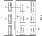
- FIG. 2 is a block diagram of the MEC device 140 and the core network 150 according to an embodiment of the disclosure.
- the MEC device may comprise a relay User Plane Function (UPF) module 141, a UPF module 142, a non-3GPP Inter-Working Function (N3IWF) module 143, a control circuit 144, an Application Function (AF) module 145 and an Access Network Service module 146.
- UPF User Plane Function
- N3IWF non-3GPP Inter-Working Function
- AF Application Function
- FIG. 2 presents a simplified block diagram in which only the elements relevant to the disclosure are shown. However, the disclosure should not be limited to what is shown in FIG. 2 .
- the MEC device 140 also can comprise other elements and function modules.
- the MEC device 140 also can establish a plurality of UPF modules. Each UPF module may serve one or more UE. Furthermore, the "UPF" in the disclosure can be regarded as an intermediate UPF (I-UPF).
- the core network 150 may comprise an Access and Mobility Function (AMF) module 151, a Session Management Function (SMF) module 152 and a Network Exposure Function (NEF) module 153.
- AMF Access and Mobility Function
- SMF Session Management Function
- NEF Network Exposure Function
- FIG. 2 presents a simplified block diagram in which only the elements relevant to the disclosure are shown. However, the disclosure should not be limited to what is shown in FIG. 2 .
- the core network 150 also can comprise other elements and function modules.
- the AMF module 151 may manage the register and authentication operations of the UE 110.
- the SMF module 152 may manage the sessions of the UE 110 and control the configurations and establishments of the UPF modules.
- the SMF module 152 may communicate with relay UPF module 141 and the UPF module 142 through a N4 interface.
- the NEF module 153 may communicate with the AF module 145 through a N33 interface.
- the AF module 145 may notify the NEF module 153 to establish an idle session between the UE 110 and the relay UPF module 141.
- the UE 110 may use the UPF module 142 to perform data transmission with the network end and obtain the service (the application corresponding to the Access Network Service module 146) from the network end.
- the core network 150 can directly communicate with the UE 110 through the UPF module 142.
- the UE 110 when the UE 110 communicates with the core network 150 through a non-3GPP access network (e.g. the first access network 120), the UE 110 needs to communicate with the core network 150 through the N3IWF module 143.
- the first access network 120 or the second access network 130 may respectively correspond to different UPF modules.
- the control circuit 144 may determine whether a trigger condition is generated.
- the trigger condition may comprise whether a handover needs to be performed on UE 110, whether to update the UPF, whether to allocate the UPF resource, and whether a slicing policy is triggered, but the disclosure should not be limited thereto.
- the control circuit 144 may notify the AF module 145 that the trigger condition is generated. After the AF module 145 receives the notification, according to the notification, the AF module 145 may determine whether the service for the UE 110 needs to be switched from the UPF module 142 to a new UPF module.
- a trigger condition e.g. handover needs to be performed on UE 110
- the control circuit 144 may notify the AF module 145 that the trigger condition is generated. After the AF module 145 receives the notification, according to the notification, the AF module 145 may determine whether the service for the UE 110 needs to be switched from the UPF module 142 to a new UPF module.
- the AF module 145 may determine whether the new UPF is activated (or the new UPF module has existed). According to an embodiment of the disclosure, if the new UPF has been activated, the AF module 145 may send notification to the NEF module 153 of the core network 150 to indicate the core network 150 to switch the service for the UE 110 from the UPF module 142 to the new UPF module.
- the AF module 145 may send notification to the NEF module 153 of the core network 150 to indicate the SMF module 152 of the core network 150 to switch the service for the UE 110 from the UPF module 142 to the relay UPF module 141 first, and the AF module 145 may continuously monitor whetherthe new UPF is activated.
- the SMF module 152 of the core network 150 has established the new UPF module in the MEC device 140
- the AF module 145 may send notification to the NEF module 153 of the core network 150 to indicate the SMF module 152 to switch the service for the UE 110 from the relay UPF module 141 to the new UPF module.
- the AF module 145 may send a notification to the NEF module 153 to indicate the SMF module 152 to perform authentication and encryption through the N3IWF module 143 to the UE 110 and the new UPF before switching the service for the UE 110 from the UPF module 142 to the new UPF module.
- the AF module 145 may send a notification to the NEF module 153 to indicate the SMF module 152 to switch the service for the UE 110 from the UPF module 142 to the new UPF module, the AF module 145 may determine whether the UE 110 has detached from the N3IWF module 143 first. When the UE 110 has detached from the N3IWF module 143, the AF module 145 may send a notification to the NEF module 153 to indicate the SMF module 152 to switch the service for the UE 110 from the UPF module 142 to the new UPF module.
- the receiving device (not shown in figures) of the UE 110 may receive a first indication from the core network 150, and the processing device (not shown in figures) of the UE 110 may switch the service for the UE 110 to a relay UPF module first based on the first indication.
- the receiving device of the UE 110 may receive a second indication from the core network 150, the processing device of the UE 110 may switch the service for the UE 110 to the second UPF module first based on the second indication.
- FIG. 3 is a flow chart illustrating a UPF switch method according to an embodiment of the disclosure.
- the UPF switch method can be applied to the MEC system 100.
- the embodiment is based on the condition of the UE 110 handing over from the second access network 130 to the first access network 120 (i.e. hand over form the 3GPP access network to the non-3GPP access network).
- the AF module 145 may notify the NEF module 153 to establish an idle session between the UE 100 and the relay UPF module 141.
- the control circuit 144 may determine whether a trigger condition is generated. If the trigger condition is not generated, the control circuit 144 may perform step S320 continuously.
- step S330 is performed.
- the control circuit 144 may notify the AF module 145 that the handover of the UE 110 will be performed.
- step S340 the AF module 145 may determine whether the service for the UE 110 needs to be switched from the current UPF module (i.e. UPF module 142) to a new UPF module (not shown in figures). If the service for the UE 110 does not need to be switched from the UPF module 142 to a new UPF module, the method backs to step S320.
- step S350 is performed.
- the AF module 145 may determine whether the new UPF module has been activated (or determine whether the new UPF exists).
- step S360 is performed.
- the AF module 145 may notify the NEF module 153 of the core network 150 to switch the service for the UE 110 from the UPF module 142 to the new UPF module.
- step S370 is performed.
- the AF module 145 may notify the NEF module 153 of the core network 150 to switch the service for the UE 110 from the UPF module 142 to the relay UPF module 141 first.
- step S380 the AF module 145 may monitor (or determine) whether the new UPF module has been activated continuously. If the new UPF module has not been activated, the AF module 145 may perform step S380 continuously.
- step S390 is performed.
- the AF module 145 may determine whether the UE 110 and the new UPF module have been authorized and encrypted through the N3IWF module 143.
- the SMF module 152 may determine whether the UE 110 and the new UPF module have been authorized and encrypted through the N3IWF module 143 first and then transmit the determination result to the NEF module 153. Then, the NEF module 153 may transmit the determination result generated by the SMF module 152 to the AF module 145.
- the AF module 145 will be able to determine whether the UE 110 and the new UPF module have been authorized and encrypted through the N3IWF module 143. If the UE 110 and the new UPF module have not been authorized and encrypted through the N3IWF module 143, the AF module 145 may perform step S390 continuously. When the UE 110 and the new UPF module have been authorized and encrypted through the N3IWF module 143, step S360 is performed. The AF module 145 may notify the NEF module 153 of the core network 150 to switch the service for the UE 110 to the new UPF module.
- step S390 does not need to be performed. That is to say, in this condition, when the SMF module 152 of the core network 150 has established the new UPF module in the MEC device 140, the AF module 145 may directly notify the NEF module 153 of the core network 150 to switch the service for the UE 110 to the new UPF module.
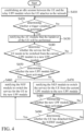
- FIG. 4 is a flow chart illustrating a UPF switch method according to another embodiment of the disclosure.
- the UPF switch method can be applied to the MEC system 100.
- the embodiment is based on the condition of the UE 110 handing over from the first access network 120 to the second access network 130 (i.e. hand over form the non-3GPP access network to the 3GPP access network).
- the AF module 145 may notify the NEF module 153 to establish an idle session between the UE 100 and the relay UPF module 141.
- the control circuit 144 may determine whether a trigger condition is generated. If the trigger condition is not generated, the control circuit 144 may perform step S420 continuously.
- step S430 is performed.
- the control circuit 144 may notify the AF module 145 that the handover of the UE 110 will be performed.
- step S440 the AF module 145 may determine whether the service for the UE 110 needs to be switched from the UPF module 142 to a new UPF module (not shown in figures). If the service for the UE 110 does not need to be switched from the UPF module 142 to a new UPF module, the method backs to step S420.
- step S350 is performed.
- the AF module 145 may determine whether the new UPF module has been activated (or determine whether the new UPF exists).
- step S460 is performed.
- the AF module 145 may notify the NEF module 153 of the core network 150 to switch the service for the UE 110 from the UPF module 142 to the new UPF module.
- step S470 is performed.
- the AF module 145 may notify the NEF module 153 of the core network 150 to switch the service for the UE 110 from the UPF module 142 to the relay UPF module 141 first.
- step S480 the AF module 145 may monitor whether the new UPF module has been activated continuously. If the new UPF module has not been activated, the AF module 145 may perform step S480 continuously.
- step S490 is performed.
- the AF module 145 may determine whether the UE 110 has detached from the N3IWF module 143. Specifically, in step S490, the SMF module 152 may determine whether the UE 110 has detached from the N3IWF module 143 first and then transmit the determination result to the NEF module 153. Then, the NEF module 153 may transmit the determination result generated by the SMF module 152 to the AF module 145. Accordingly, the AF module 145 will be able to determine whether the UE 110 has detached from the N3IWF module 143.
- the AF module 145 may perform step S490 continuously. If the UE 110 has detached from the N3IWF module 143, step S460 is performed. The AF module 145 may notify the NEF module 153 of the core network 150 to switch the service for the UE 110 to the new UPF module.
- step S390 needs to be performed between step S480 and step S490. That is to say, after the SMF module 152 of the core network 150 has established the new UPF module in the MEC device 140, the AF module 145 may determine whether the UE 110 and the new UPF module have been authorized and encrypted through the N3IWF module 143 first. Specifically, the SMF module 152 may determine whether the UE 110 and the new UPF module have been authorized and encrypted through the N3IWF module 143 first and then transmit the determination result to the NEF module 153.
- the NEF module 153 may transmit the determination result generated by the SMF module 152 to the AF module 145. Accordingly, the AF module 145 will be able to determine whether the UE 110 and the new UPF module have been authorized and encrypted through the N3IWF module 143. Until the UE 110 and the new UPF module have been authorized and encrypted through the N3IWF module 143, step S490 is not performed.
- FIG. 5 is a flow chart illustrating a UPF switch method according to another embodiment of the disclosure.
- the UPF switch method can be applied to the MEC system 100.
- the embodiment is based on the condition of the UE 110 having a low priority.
- the AF module 145 may notify the NEF module 153 to establish an idle session between the UE 100 and the relay UPF module 141.
- the control circuit 144 may determine whether a trigger condition is generated. If the trigger condition is not generated, the control circuit 144 may perform step S520 continuously.
- step S530 is performed.
- the control circuit 144 may notify the AF module 145 that the UE 110 with low priority needs to be removed from the current UPF module (i.e. UPF module 142).
- the AF module 145 may determine whether a new UPF module has been activated (or determine whether a new UPF exists).
- step S550 the AF module 145 may notify the NEF module 153 of the core network 150 to switch the service for the UE 110 from the UPF module 142 to the new UPF module.
- step S560 the AF module 145 may notify the NEF module 153 of the core network 150 to switch the service for the UE 110 from the UPF module 142 to the relay UPF module 141 first.
- step S570 the AF module 145 may monitor whether the new UPF module has been activated continuously. If the new UPF module has not been activated, the AF module 145 may perform step S570 continuously.
- step S580 is performed.
- the AF module 145 may determine whether the UE 110 and the new UPF module have been authorized and encrypted through the N3IWF module 143.
- the SMF module 152 may determine whether the UE 110 and the new UPF module have been authorized and encrypted through the N3IWF module 143 first and then transmit the determination result to the NEF module 153. Then, the NEF module 153 may transmit the determination result generated by the SMF module 152 to the AF module 145.
- the AF module 145 will be able to determine whether the UE 110 and the new UPF module have been authorized and encrypted through the N3IWF module 143. If the UE 110 and the new UPF module have not been authorized and encrypted through the N3IWF module 143, the AF module 145 may perform step S580 continuously. When the UE 110 and the new UPF module have been authorized and encrypted through the N3IWF module 143, step S550 is performed. The AF module 145 may notify the NEF module 153 of the core network 150 to switch the service for the UE 110 to the new UPF module.
- FIG. 6 is a flow chart illustrating a UPF switch method according to an embodiment of the disclosure.
- the UPF switch method can be applied to the MEC system 100.
- step S610 when a UE of the MEC system 100 attaches to a network, an MEC device of the MEC system 100 may establish an idle session between the UE and a relay UPF module.
- step S620 when the MEC device of the MEC system 100 determines that the service for the UE needs to be switched from a first UPF module and a second UPF module, and the second UPF module has not been activated, the MEC device of the MEC system 100 indicate a core network of the MEC system 100 to switch the service for the UE from the first UP to the relay UPF first.
- the MEC device of the MEC system 100 may determine whether the second UPF has been activated. When the MEC device of the MEC system 100 determines that the second UPF has been activated, the MEC device may indicate the core network of the MEC system 100 to switch the service for the UE from the first UPF module to the second UPF module.
- the MEC device when the service for the UE needs to be switched from a UPF module to another UPF module, the MEC device can determine whether to switch the service for the UE to a relay UPF module first. Therefore, in the UPF switch methods provided in the disclosure, the interruption of the service for the UE can be avoided when the service for the UE needs to be switched from a UPF module to another UPF module.
- a software module e.g., including executable instructions and related data
- other data may reside in a data memory such as RAM memory, flash memory, ROM memory, EPROM memory, EEPROM memory, registers, a hard disk, a removable disk, a CD-ROM, or any other form of computer-readable storage medium known in the art.
- a sample storage medium may be coupled to a machine such as, for example, a computer/processor (which may be referred to herein, for convenience, as a "processor”) such that the processor can read information (e.g., code) from and write information to the storage medium.
- a sample storage medium may be integral to the processor.
- the processor and the storage medium may reside in an ASIC.
- the ASIC may reside in user equipment.
- the processor and the storage medium may reside as discrete components in user equipment.
- any suitable computer-program product may comprise a computer-readable medium comprising codes relating to one or more of the aspects of the disclosure.
- a computer program product may comprise packaging materials.
Abstract
Description
- The disclosure generally relates to User Plane Function (UPF) technology, and more particularly, to a UPF switch technology in which a relay UPF is used to avoid service interruptions to the user equipment (UE) when the UPF switch occurs.
- As the use of mobile devices becomes more widespread and as network service applications (e.g. video streams, virtual reality, autonomous vehicles, and so on) have progressed, the requirements on data traffic have increased. Therefore, Multi-Access Edge Computing (MEC) is used in 5G communication for the increasing data traffic requirements and computations. The MEC is used to provide cloud computation capability and an Information Technology (IT) environment to the edge of the mobile network. Its main purpose is to reduce the computation performed by the core network apparatus and assist operators in establishing a specific mobile experience platform for the customers.
- However, in the structure of 5G MEC, when the User Plane Function (UPF) needs to be switched (e.g. a handover is taking place on the user equipment (UE)), the service of the UE may be interrupted because of the UPF switch. As a result, the user experience will suffer.
- A Low Earth Orbit (LEO) satellite system and a handover method for the LEO satellites are provided.
- An embodiment of the disclosure provides a Multi-Access Edge Computing (MEC) system. The MEC system includes user equipment (UE), an MEC device, and a core network. The MEC device includes a relay User Plane Function (UPF) module, a first UPF module, and a second UPF module. The core network performs a UPF path management corresponding to the UE based on a notification of the MEC device. When the UE attaches to a network, the MEC device establishes an idle session between the UE and the relay UPF module. When the MEC device determines that a service for the UE needs to be switched from the first UPF module to the second UPF module and the second UPF module has not been activated, the MEC device notifies the core network to switch the service for the UE from the first UPF module to the relay UPF module first.
- An embodiment of the disclosure provides a Multi-Access Edge Computing (MEC) device. The MEC device includes a relay User Plane Function (UPF) module and an Application Function (AF) module. The AF module establishes an idle session between the user equipment (UE) and the relay UPF module when the UE attaches to a network. In addition, the AF module determines whether a service for the UE needs to be switched from a first UPF module to a second UPF module. When the AF module determines that the service for the UE needs to be switched from the first UPF module to the second UPF module and the second UPF module has not been activated, the AF module notifies a core network to switch the service for the UE from the first UPF module to the relay UPF module first.
- An embodiment of the disclosure provides user equipment (UE). The UE includes a receiving device and a processing device. When a Multi-Access Edge Computing (MEC) device determines that a service for the UE needs to be switched from a first User Plane Function (UPF) module to the second UPF module and the second UPF module has not been activated, the receiving device receives a first indication from a core network, and based on the first indication, the processing device switches to a relay UPF module to perform the service.
- An embodiment of the disclosure provides a User Plane Function (UPF) switch method. The UPF switch method is applied to a Multi-Access Edge Computing (MEC) system. The UPF switch method includes the following steps. When user equipment (UE) of the MEC system attaches to a network, an MEC device of the MEC system establishes an idle session between the UE and a relay UPF module. When the MEC device determines that a service for the UE needs to be switched from a first UPF module to a second UPF module, and the second UPF module has not been activated, the MEC device notifies the core network of the MEC system to switch the service for the UE from the first UPF module to the relay UPF first.
- Other aspects and features of the disclosure will become apparent to those with ordinary skill in the art upon review of the following descriptions of specific embodiments of MEC system, MEC device, UE and UPF switch method.
- The disclosure will become more fully understood by referring to the following detailed description with reference to the accompanying drawings, wherein:
-
FIG. 1 is a block diagram of a Multi-Access Edge Computing (MEC)system 100 according to an embodiment of the disclosure; -
FIG. 2 is a block diagram of theMEC device 140 and thecore network 150 according to an embodiment of the disclosure; -
FIG. 3 is a flow chart illustrating a UPF switch method according to an embodiment of the disclosure; -
FIG. 4 is a flow chart illustrating a UPF switch method according to another embodiment of the disclosure; -
FIG. 5 is a flow chart illustrating a UPF switch method according to another embodiment of the disclosure; and -
FIG. 6 is a flow chart illustrating a UPF switch method according to an embodiment of the disclosure. - The following description is of the best-contemplated mode of carrying out the disclosure. This description is made for the purpose of illustrating the general principles of the disclosure and should not be taken in a limiting sense. The scope of the disclosure is best determined by reference to the appended claims.
-
FIG. 1 is a block diagram of a Multi-Access Edge Computing (MEC)system 100 according to an embodiment of the disclosure. As shown inFIG. 1 , theMEC system 100 may comprise user equipment (UE) 110, afirst access network 120, asecond access network 130, anMEC device 140 and acore network 150. It should be noted thatFIG. 1 presents a simplified block diagram in which only the elements relevant to the disclosure are shown. However, the disclosure should not be limited to what is shown inFIG. 1 . - According to an embodiment of the disclosure, the UE 110 may be a smart phone, personal data assistant (PDA), a paging device, a note book, a desktop computer, a wireless portable device or any computing device with wireless communication interface.
- According to an embodiment of the disclosure, the
first access network 120 may be a non-3GPP access network, e.g. a Wi-Fi access point (AP), but the disclosure should not be limited thereto. In addition, according to an embodiment of the disclosure, thesecond access network 130 may be a 3GPP access network, e.g. base station (e.g. gNB), but the disclosure should not be limited thereto. -
FIG. 2 is a block diagram of theMEC device 140 and thecore network 150 according to an embodiment of the disclosure. As shown inFIG. 2 , the MEC device may comprise a relay User Plane Function (UPF)module 141, aUPF module 142, a non-3GPP Inter-Working Function (N3IWF)module 143, acontrol circuit 144, an Application Function (AF)module 145 and an AccessNetwork Service module 146. It should be noted thatFIG. 2 presents a simplified block diagram in which only the elements relevant to the disclosure are shown. However, the disclosure should not be limited to what is shown inFIG. 2 . TheMEC device 140 also can comprise other elements and function modules. In addition, there is only oneUPF module 142 inFIG. 2 , but the disclosure should not be limited thereto. TheMEC device 140 also can establish a plurality of UPF modules. Each UPF module may serve one or more UE. Furthermore, the "UPF" in the disclosure can be regarded as an intermediate UPF (I-UPF). - In addition, as shown in
FIG. 2 , thecore network 150 may comprise an Access and Mobility Function (AMF)module 151, a Session Management Function (SMF)module 152 and a Network Exposure Function (NEF)module 153. It should be noted thatFIG. 2 presents a simplified block diagram in which only the elements relevant to the disclosure are shown. However, the disclosure should not be limited to what is shown inFIG. 2 . Thecore network 150 also can comprise other elements and function modules. According to the embodiments of the disclosure, the AMFmodule 151 may manage the register and authentication operations of the UE 110. TheSMF module 152 may manage the sessions of the UE 110 and control the configurations and establishments of the UPF modules. TheSMF module 152 may communicate withrelay UPF module 141 and theUPF module 142 through a N4 interface. TheNEF module 153 may communicate with theAF module 145 through a N33 interface. - According to an embodiment of the disclosure, when the
UE 110 attaches to the network through thefirst access network 120 or thesecond access network 130, theAF module 145 may notify theNEF module 153 to establish an idle session between theUE 110 and therelay UPF module 141. - In addition, when the
UE 110 attaches to the network through thefirst access network 120 or thesecond access network 130, theUE 110 may use theUPF module 142 to perform data transmission with the network end and obtain the service (the application corresponding to the Access Network Service module 146) from the network end. According to an embodiment of the disclosure, when theUE 110 communicates with thecore network 150 through a 3GPP access network (e.g. the second access network 130), thecore network 150 can directly communicate with theUE 110 through theUPF module 142. According to another embodiment of the disclosure, when theUE 110 communicates with thecore network 150 through a non-3GPP access network (e.g. the first access network 120), theUE 110 needs to communicate with thecore network 150 through theN3IWF module 143. It should be noted that there is only oneUPF module 142 inFIG. 2 , but the disclosure should not be limited thereto. Thefirst access network 120 or thesecond access network 130 may respectively correspond to different UPF modules. - According to an embodiment of the disclosure, the
control circuit 144 may determine whether a trigger condition is generated. According to an embodiment of the disclosure, the trigger condition may comprise whether a handover needs to be performed onUE 110, whether to update the UPF, whether to allocate the UPF resource, and whether a slicing policy is triggered, but the disclosure should not be limited thereto. - According to an embodiment of the disclosure, when the
control circuit 144 determines that a trigger condition is generated (e.g. handover needs to be performed on UE 110), thecontrol circuit 144 may notify theAF module 145 that the trigger condition is generated. After theAF module 145 receives the notification, according to the notification, theAF module 145 may determine whether the service for theUE 110 needs to be switched from theUPF module 142 to a new UPF module. - When the
AF module 145 determines that the service for theUE 110 needs to be switched from theUPF module 142 to a new UPF module, theAF module 145 may determine whether the new UPF is activated (or the new UPF module has existed). According to an embodiment of the disclosure, if the new UPF has been activated, theAF module 145 may send notification to theNEF module 153 of thecore network 150 to indicate thecore network 150 to switch the service for theUE 110 from theUPF module 142 to the new UPF module. - According to an embodiment of the disclosure, if the new UPF has not been activated, the
AF module 145 may send notification to theNEF module 153 of thecore network 150 to indicate theSMF module 152 of thecore network 150 to switch the service for theUE 110 from theUPF module 142 to therelay UPF module 141 first, and theAF module 145 may continuously monitor whetherthe new UPF is activated. When theSMF module 152 of thecore network 150 has established the new UPF module in theMEC device 140, theAF module 145 may send notification to theNEF module 153 of thecore network 150 to indicate theSMF module 152 to switch the service for theUE 110 from therelay UPF module 141 to the new UPF module. - According to an embodiment of the disclosure, if the new UPF module corresponds to a non-3GPP access network (e.g. the first access network 120), the
AF module 145 may send a notification to theNEF module 153 to indicate theSMF module 152 to perform authentication and encryption through theN3IWF module 143 to theUE 110 and the new UPF before switching the service for theUE 110 from theUPF module 142 to the new UPF module. - In addition, according to an embodiment of the disclosure, if the new UPF module corresponds to a non-3GPP access network (e.g. the first access network 120), before the
AF module 145 may send a notification to theNEF module 153 to indicate theSMF module 152 to switch the service for theUE 110 from theUPF module 142 to the new UPF module, theAF module 145 may determine whether theUE 110 has detached from theN3IWF module 143 first. When theUE 110 has detached from theN3IWF module 143, theAF module 145 may send a notification to theNEF module 153 to indicate theSMF module 152 to switch the service for theUE 110 from theUPF module 142 to the new UPF module. - According to an embodiment of the disclosure, when the service for the
UE 110 from afirst UPF module 142 to a second UPF module and the second UPF module has not been activated, the receiving device (not shown in figures) of theUE 110 may receive a first indication from thecore network 150, and the processing device (not shown in figures) of theUE 110 may switch the service for theUE 110 to a relay UPF module first based on the first indication. After the second UPF module has been activated, the receiving device of theUE 110 may receive a second indication from thecore network 150, the processing device of theUE 110 may switch the service for theUE 110 to the second UPF module first based on the second indication. -
FIG. 3 is a flow chart illustrating a UPF switch method according to an embodiment of the disclosure. The UPF switch method can be applied to theMEC system 100. In addition, the embodiment is based on the condition of theUE 110 handing over from thesecond access network 130 to the first access network 120 (i.e. hand over form the 3GPP access network to the non-3GPP access network). In step S310, when theUE 110 attaches to the network, theAF module 145 may notify theNEF module 153 to establish an idle session between theUE 100 and therelay UPF module 141. In step S320, thecontrol circuit 144 may determine whether a trigger condition is generated. If the trigger condition is not generated, thecontrol circuit 144 may perform step S320 continuously. - When the
control circuit 144 determines that theUE 110 needs to hand over from thesecond access network 130 to the first access network 120 (i.e. the trigger condition is generated), step S330 is performed. In step S330, thecontrol circuit 144 may notify theAF module 145 that the handover of theUE 110 will be performed. In step S340, theAF module 145 may determine whether the service for theUE 110 needs to be switched from the current UPF module (i.e. UPF module 142) to a new UPF module (not shown in figures). If the service for theUE 110 does not need to be switched from theUPF module 142 to a new UPF module, the method backs to step S320. If the service for theUE 110 needs to be switched from theUPF module 142 to a new UPF module, step S350 is performed. In step S350, theAF module 145 may determine whether the new UPF module has been activated (or determine whether the new UPF exists). - If the new UPF module has been activated, step S360 is performed. In step S360, the
AF module 145 may notify theNEF module 153 of thecore network 150 to switch the service for theUE 110 from theUPF module 142 to the new UPF module. If the new UPF module has not been activated, step S370 is performed. In step S370, theAF module 145 may notify theNEF module 153 of thecore network 150 to switch the service for theUE 110 from theUPF module 142 to therelay UPF module 141 first. In step S380, theAF module 145 may monitor (or determine) whether the new UPF module has been activated continuously. If the new UPF module has not been activated, theAF module 145 may perform step S380 continuously. - When the
SMF module 152 of thecore network 150 has established the new UPF module in theMEC device 140, step S390 is performed. In step S390, theAF module 145 may determine whether theUE 110 and the new UPF module have been authorized and encrypted through theN3IWF module 143. Specifically, in step S390, theSMF module 152 may determine whether theUE 110 and the new UPF module have been authorized and encrypted through theN3IWF module 143 first and then transmit the determination result to theNEF module 153. Then, theNEF module 153 may transmit the determination result generated by theSMF module 152 to theAF module 145. Accordingly, theAF module 145 will be able to determine whether theUE 110 and the new UPF module have been authorized and encrypted through theN3IWF module 143. If theUE 110 and the new UPF module have not been authorized and encrypted through theN3IWF module 143, theAF module 145 may perform step S390 continuously. When theUE 110 and the new UPF module have been authorized and encrypted through theN3IWF module 143, step S360 is performed. TheAF module 145 may notify theNEF module 153 of thecore network 150 to switch the service for theUE 110 to the new UPF module. - It should be noted that in the condition of the condition of the
UE 110 handing over from thesecond access network 130 to another 3GPP access network (i.e. hand over form the 3GPP access network to another 3GPP access network), step S390 does not need to be performed. That is to say, in this condition, when theSMF module 152 of thecore network 150 has established the new UPF module in theMEC device 140, theAF module 145 may directly notify theNEF module 153 of thecore network 150 to switch the service for theUE 110 to the new UPF module. -
FIG. 4 is a flow chart illustrating a UPF switch method according to another embodiment of the disclosure. The UPF switch method can be applied to theMEC system 100. In addition, the embodiment is based on the condition of theUE 110 handing over from thefirst access network 120 to the second access network 130 (i.e. hand over form the non-3GPP access network to the 3GPP access network). In step S410, when theUE 110 attaches to the network, theAF module 145 may notify theNEF module 153 to establish an idle session between theUE 100 and therelay UPF module 141. In step S420, thecontrol circuit 144 may determine whether a trigger condition is generated. If the trigger condition is not generated, thecontrol circuit 144 may perform step S420 continuously. - When the
control circuit 144 determines that theUE 110 needs to hand over from thefirst access network 120 to the second access network 130 (i.e. the trigger condition is generated), step S430 is performed. In step S430, thecontrol circuit 144 may notify theAF module 145 that the handover of theUE 110 will be performed. In step S440, theAF module 145 may determine whether the service for theUE 110 needs to be switched from theUPF module 142 to a new UPF module (not shown in figures). If the service for theUE 110 does not need to be switched from theUPF module 142 to a new UPF module, the method backs to step S420. If the service for theUE 110 needs to be switched from theUPF module 142 to a new UPF module, step S350 is performed. In step S450, theAF module 145 may determine whether the new UPF module has been activated (or determine whether the new UPF exists). - If the new UPF module has been activated, step S460 is performed. In step S460, the
AF module 145 may notify theNEF module 153 of thecore network 150 to switch the service for theUE 110 from theUPF module 142 to the new UPF module. If the new UPF module has not been activated, step S470 is performed. In step S470, theAF module 145 may notify theNEF module 153 of thecore network 150 to switch the service for theUE 110 from theUPF module 142 to therelay UPF module 141 first. In step S480, theAF module 145 may monitor whether the new UPF module has been activated continuously. If the new UPF module has not been activated, theAF module 145 may perform step S480 continuously. - When the
SMF module 152 of thecore network 150 has established the new UPF module in theMEC device 140, step S490 is performed. In step S490, theAF module 145 may determine whether theUE 110 has detached from theN3IWF module 143. Specifically, in step S490, theSMF module 152 may determine whether theUE 110 has detached from theN3IWF module 143 first and then transmit the determination result to theNEF module 153. Then, theNEF module 153 may transmit the determination result generated by theSMF module 152 to theAF module 145. Accordingly, theAF module 145 will be able to determine whether theUE 110 has detached from theN3IWF module 143. If theUE 110 has not detached from theN3IWF module 143, theAF module 145 may perform step S490 continuously. If theUE 110 has detached from theN3IWF module 143, step S460 is performed. TheAF module 145 may notify theNEF module 153 of thecore network 150 to switch the service for theUE 110 to the new UPF module. - It should be noted that in the condition of the
UE 110 handing over from thefirst access network 120 to another non-3GPP access network 130 (i.e. hand over form the non-3GPP access network to another non-3GPP access network), step S390 needs to be performed between step S480 and step S490. That is to say, after theSMF module 152 of thecore network 150 has established the new UPF module in theMEC device 140, theAF module 145 may determine whether theUE 110 and the new UPF module have been authorized and encrypted through theN3IWF module 143 first. Specifically, theSMF module 152 may determine whether theUE 110 and the new UPF module have been authorized and encrypted through theN3IWF module 143 first and then transmit the determination result to theNEF module 153. Then, theNEF module 153 may transmit the determination result generated by theSMF module 152 to theAF module 145. Accordingly, theAF module 145 will be able to determine whether theUE 110 and the new UPF module have been authorized and encrypted through theN3IWF module 143. Until theUE 110 and the new UPF module have been authorized and encrypted through theN3IWF module 143, step S490 is not performed. -
FIG. 5 is a flow chart illustrating a UPF switch method according to another embodiment of the disclosure. The UPF switch method can be applied to theMEC system 100. In addition, the embodiment is based on the condition of theUE 110 having a low priority. In step S510, when theUE 110 attaches to the network, theAF module 145 may notify theNEF module 153 to establish an idle session between theUE 100 and therelay UPF module 141. In step S520, thecontrol circuit 144 may determine whether a trigger condition is generated. If the trigger condition is not generated, thecontrol circuit 144 may perform step S520 continuously. - When the
control circuit 144 determines that the resource of theUPF module 142 corresponding to the slice of the UE (not shown in figures) with high priority (i.e. the trigger condition is generated) is not enough, step S530 is performed. In step S530, thecontrol circuit 144 may notify theAF module 145 that theUE 110 with low priority needs to be removed from the current UPF module (i.e. UPF module 142). In step S540, theAF module 145 may determine whether a new UPF module has been activated (or determine whether a new UPF exists). - If the new UPF module has been activated, step S550 is performed. In step S550, the
AF module 145 may notify theNEF module 153 of thecore network 150 to switch the service for theUE 110 from theUPF module 142 to the new UPF module. If the new UPF module has not been activated, step S560 is performed. In step S560, theAF module 145 may notify theNEF module 153 of thecore network 150 to switch the service for theUE 110 from theUPF module 142 to therelay UPF module 141 first. In step S570, theAF module 145 may monitor whether the new UPF module has been activated continuously. If the new UPF module has not been activated, theAF module 145 may perform step S570 continuously. - When the
SMF module 152 of thecore network 150 has established the new UPF module in theMEC device 140, step S580 is performed. In step S580, theAF module 145 may determine whether theUE 110 and the new UPF module have been authorized and encrypted through theN3IWF module 143. Specifically, in step S580, theSMF module 152 may determine whether theUE 110 and the new UPF module have been authorized and encrypted through theN3IWF module 143 first and then transmit the determination result to theNEF module 153. Then, theNEF module 153 may transmit the determination result generated by theSMF module 152 to theAF module 145. Accordingly, theAF module 145 will be able to determine whether theUE 110 and the new UPF module have been authorized and encrypted through theN3IWF module 143. If theUE 110 and the new UPF module have not been authorized and encrypted through theN3IWF module 143, theAF module 145 may perform step S580 continuously. When theUE 110 and the new UPF module have been authorized and encrypted through theN3IWF module 143, step S550 is performed. TheAF module 145 may notify theNEF module 153 of thecore network 150 to switch the service for theUE 110 to the new UPF module. - The steps of the UPF switch method associated with updating UPF or allocating resources are similar to the steps illustrated in
FIG. 5 . Therefore, details will not repeat again. -
FIG. 6 is a flow chart illustrating a UPF switch method according to an embodiment of the disclosure. The UPF switch method can be applied to theMEC system 100. As shown inFIG. 6 , in step S610, when a UE of theMEC system 100 attaches to a network, an MEC device of theMEC system 100 may establish an idle session between the UE and a relay UPF module. - In step S620, when the MEC device of the
MEC system 100 determines that the service for the UE needs to be switched from a first UPF module and a second UPF module, and the second UPF module has not been activated, the MEC device of theMEC system 100 indicate a core network of theMEC system 100 to switch the service for the UE from the first UP to the relay UPF first. - In the UPF switch method, the MEC device of the
MEC system 100 may determine whether the second UPF has been activated. When the MEC device of theMEC system 100 determines that the second UPF has been activated, the MEC device may indicate the core network of theMEC system 100 to switch the service for the UE from the first UPF module to the second UPF module. - According to the UPF switch methods provided in the disclosure, when the service for the UE needs to be switched from a UPF module to another UPF module, the MEC device can determine whether to switch the service for the UE to a relay UPF module first. Therefore, in the UPF switch methods provided in the disclosure, the interruption of the service for the UE can be avoided when the service for the UE needs to be switched from a UPF module to another UPF module.
- Use of ordinal terms such as "first", "second", "third", etc., in the disclosure and claims is for description. It does not by itself connote any order or relationship.
- The steps of the method described in connection with the aspects disclosed herein may be embodied directly in hardware, in a software module executed by a processor, or in a combination of the two. A software module (e.g., including executable instructions and related data) and other data may reside in a data memory such as RAM memory, flash memory, ROM memory, EPROM memory, EEPROM memory, registers, a hard disk, a removable disk, a CD-ROM, or any other form of computer-readable storage medium known in the art. A sample storage medium may be coupled to a machine such as, for example, a computer/processor (which may be referred to herein, for convenience, as a "processor") such that the processor can read information (e.g., code) from and write information to the storage medium. A sample storage medium may be integral to the processor. The processor and the storage medium may reside in an ASIC. The ASIC may reside in user equipment. Alternatively, the processor and the storage medium may reside as discrete components in user equipment. Moreover, in some aspects any suitable computer-program product may comprise a computer-readable medium comprising codes relating to one or more of the aspects of the disclosure. In some aspects a computer program product may comprise packaging materials.
- The above paragraphs describe many aspects. Obviously, the teaching of the disclosure can be accomplished by many methods, and any specific configurations or functions in the disclosed embodiments only present a representative condition. Those who are skilled in this technology will understand that all of the disclosed aspects in the disclosure can be applied independently or be incorporated.
- While the disclosure has been described by way of example and in terms of preferred embodiment, it should be understood that the disclosure is not limited thereto. Those who are skilled in this technology can still make various alterations and modifications without departing from the scope of this disclosure. Therefore, the scope of the present disclosure shall be defined and protected by the following claims and their equivalents.
Claims (16)
- A Multi-Access Edge Computing, MEC, system (100), comprising:a user equipment (110), UE;an MEC device (140), comprising a relay User Plane Function, UPF, module (141), a first UPF module (142), and a second UPF module; anda core network (150), performing a UPF path management corresponding to the UE (110) based on a notification from the MEC device (140),wherein when the UE (110) attaches to a network, the MEC device (140) establishes an idle session between the UE (110) and the relay UPF module (141),wherein when the MEC device (140) determines that a service for the UE (110) needs to be switched from the first UPF module (142) to the second UPF module and the second UPF module has not been activated, the MEC device (140) notifies the core network (150) to switch the service for the UE (110) from the first UPF module (142) to the relay UPF module (141) first.
- The MEC system (100) as claimed in claim 1, wherein the MEC device (140) determines whether a trigger condition is generated, wherein when the trigger condition is generated, the MEC device (140) determines whether the service for the UE (110) needs to be switched from the first UPF module (142) to the second UPF module, and if the service for the UE (110) needs to be switched from the first UPF module (142) to the second UPF module, the MEC device (140) determines whether the second UPF module has been activated.
- The MEC system (100) as claimed in claim 2, wherein when the MEC device (140) determines that the second UPF module has been activated, the MEC device (140) notifies the core network (150) to switch the service for the UE (110) from the first UPF module (142) to the second UPF module or when the MEC device (140) determines that the second UPF module has not been activated, the MEC device (140) waits for the core network (150) to activate the second UPF module, and when the second UPF module has been activated, the MEC device (140) notifies the core network (150) to switch the service for the UE (110) from the relay UPF module (141) to the second UPF module.
- The MEC system (100) as claimed in claim 3, wherein before the MEC device (140) notifies the core network (150) to switch the service for the UE (110) from the relay UPF module (141) to the second UPF module, the MEC device (140) authorizes the UE (110) through a non-3GPP Inter-Working Function, N3IWF, module (143).
- The MEC system (100) as claimed in one of claims 1-4, wherein an Application Function, AF, module (145) of the MEC device (140) notifies a Network Exposure Function (153), NEF, of the core network (150) through a communication interface to perform the UPF path management corresponding to the UE (110).
- The MEC system (100) as claimed in claim 5, wherein the communication interface is an N33 interface.
- A Multi-Access Edge Computing, MEC, device (140), comprising:a relay User Plane Function, UPF, module (141); andan Application Function, AF, module (145), establishing an idle session between a user equipment (110), UE, and the relay UPF module (141) when the UE (110) attaches to a network, and determining whether a service for the UE (110) needs to be switched from a first UPF module (142) to a second UPF module,wherein when the AF module (145) determines that the service for the UE (110) needs to be switched from the first UPF module (142) to the second UPF module and the second UPF module has not been activated, the AF module (145) notifies a core network (150) to switch the service for the UE (110) from the first UPF module (142) to the relay UPF module (141) first.
- The MEC device (140) as claimed in claim 7, further comprising:
a control circuit (144), determining whether a trigger condition is generated, wherein when the trigger condition is generated, the AF module (145) determines whether the service for the UE (110) needs to be switched from the first UPF module (142) to the second UPF module, and if the AF module (145) determines that the service for the UE (110) needs to be switched from the first UPF module (142) to the second UPF module, the AF module (145) determines whether the second UPF module has been activated. - The MEC device (140) as claimed in claim 8, wherein when the AF module (145) determines that the second UPF module has been activated, the AF module (145) notifies the core network (150) to switch the service for the UE (110) from the first UPF module (142) to the second UPF module or when the AF module (145) determines that the second UPF module has not been activated, the AF module (145) waits for the core network (150) to activate the second UPF module, and when the second UPF module has been activated, the AF module (145) notifies the core network (150) to switch the service for the UE (110) from the relay UPF module (141) to the second UPF module.
- The MEC device (140) as claimed in claim 9, further comprising:
a non-3GPP Inter-Working Function, N3IWF, module (143), wherein before the AF module (145) notifies the core network (150) to switch the service for the UE (110) from the relay UPF module (141) to the second UPF module, the AF module (145) indicates the N3IWF module (143) to authorize the UE (110). - A user equipment (110), UE, comprising:a receiving device; anda processing device,wherein when a Multi-Access Edge Computing, MEC, device (140) determines that a service for the UE (110) needs to be switched from a first User Plane Function, UPF, module (142) to the second UPF module and the second UPF module has not been activated, the receiving device receives a first indication from a core network (150), and based on the first indication, the processing device switches to a relay UPF module (141) to perform the service.
- The UE (110) as claimed in claim 11, wherein when the second UPF module has been activated, the receiving device receives a second indication from the core network (150), and based on the second indication, the processing device switches to the second UPF module to perform the service.
- A User Plane Function, UPF, switch method, applied in a Multi-Access Edge Computing, MEC, system (100), comprising:when a user equipment (110), UE, of the MEC system (100) attaches to a network, an MEC device (140) of the MEC system (100) establishes an idle session between the UE (110) and a relay UPF module (141); andwhen the MEC device (140) determines that a service for the UE (110) needs to be switched from a first UPF module (142) to a second UPF module and the second UPF module has not been activated, the MEC device (140) notifies a core network (150) of the MEC system (100) to switch the service for the UE (110) from the first UPF module (142) to the relay UPF (141) first.
- The UPF switch method as claimed in claim 13, further comprising:determining, by the MEC device (140), whether a trigger condition is generated;when the trigger condition is generated, determining, by the MEC device (140), whether the service for the UE (110) needs to be switched from the first UPF module (142) to the second UPF module; andif the service for the UE (110) needs to be switched from the first UPF module (142) to the second UPF module, determining by the MEC device (140), whether the second UPF module has been activated.
- The UPF switch method as claimed in claim 14, further comprising:when the MEC device (140) determines that the second UPF module has been activated, notifying, by the MEC device (140), the core network (150) to switch the service for the UE (110) from the first UPF module (142) to the second UPF module orwhen the MEC device (140) determines that the second UPF module has not been activated, waiting for, by the MEC device (140), the core network (150) to activate the second UPF module, and when the second UPF module has been activated, notifying, by the MEC device (140), the core network (150) to switch the service for the UE (110) from the relay UPF module (141) to the second UPF module.
- The UPF switch method as claimed in claim 15, further comprising:
before the MEC device (140) notifies the core network (150) to switch the service for the UE (110) from the relay UPF module (141) to the second UPF module, authorizing, by the MEC device (140), the UE (110) through a non-3GPP Inter-Working Function, N3IWF, module (143).
Applications Claiming Priority (1)
| Application Number | Priority Date | Filing Date | Title |
|---|---|---|---|
| TW111106974A TWI789255B (en) | 2022-02-25 | 2022-02-25 | Multi-access edge computing (mec) system, mec device, user equipment and user plane function (upf) switch method |
Publications (1)
| Publication Number | Publication Date |
|---|---|
| EP4236462A1 true EP4236462A1 (en) | 2023-08-30 |
Family
ID=82404388
Family Applications (1)
| Application Number | Title | Priority Date | Filing Date |
|---|---|---|---|
| EP22184080.4A Pending EP4236462A1 (en) | 2022-02-25 | 2022-07-11 | Multi-access edge computing (mec) system, mec device, user equipment and user plane function (upf) switch method |
Country Status (4)
| Country | Link |
|---|---|
| US (1) | US20230276329A1 (en) |
| EP (1) | EP4236462A1 (en) |
| JP (1) | JP7469389B2 (en) |
| TW (1) | TWI789255B (en) |
Citations (4)
| Publication number | Priority date | Publication date | Assignee | Title |
|---|---|---|---|---|
| US20180198867A1 (en) * | 2017-01-09 | 2018-07-12 | Huawei Technologies Co., Ltd. | System and methods for session management |
| US20190007992A1 (en) * | 2017-07-03 | 2019-01-03 | Electronics And Telecommunications Research Institute | Network triggered service request method and user equipment (ue) triggered service request method |
| WO2021188628A1 (en) * | 2020-03-17 | 2021-09-23 | Ofinno, Llc | Session management for processing offload |
| US20210352564A1 (en) * | 2018-10-05 | 2021-11-11 | Samsung Electronics Co., Ltd. | Method and apparatus for supporting transfer of mobile edge computing in wireless communication system |
Family Cites Families (6)
| Publication number | Priority date | Publication date | Assignee | Title |
|---|---|---|---|---|
| EP3435705B1 (en) | 2017-07-26 | 2021-03-31 | NTT DoCoMo, Inc. | Communication relay and method for redirecting data packets |
| CN110290561B (en) * | 2018-03-19 | 2020-12-04 | 大唐移动通信设备有限公司 | Local service sending method and network equipment |
| US11224093B2 (en) * | 2018-08-13 | 2022-01-11 | Ofinno, Llc | Network initiated UPF sessions transfer |
| CN114884612A (en) | 2019-06-24 | 2022-08-09 | 华为技术有限公司 | Method and device for transmitting service message |
| CN112714413A (en) | 2019-10-25 | 2021-04-27 | 中国移动通信有限公司研究院 | Internet of vehicles service processing method, equipment and storage medium |
| WO2021189269A1 (en) * | 2020-03-24 | 2021-09-30 | 华为技术有限公司 | Method and apparatus for implementing service continuity |
-
2022
- 2022-02-25 TW TW111106974A patent/TWI789255B/en active
- 2022-06-07 US US17/834,373 patent/US20230276329A1/en active Pending
- 2022-07-11 JP JP2022111206A patent/JP7469389B2/en active Active
- 2022-07-11 EP EP22184080.4A patent/EP4236462A1/en active Pending
Patent Citations (4)
| Publication number | Priority date | Publication date | Assignee | Title |
|---|---|---|---|---|
| US20180198867A1 (en) * | 2017-01-09 | 2018-07-12 | Huawei Technologies Co., Ltd. | System and methods for session management |
| US20190007992A1 (en) * | 2017-07-03 | 2019-01-03 | Electronics And Telecommunications Research Institute | Network triggered service request method and user equipment (ue) triggered service request method |
| US20210352564A1 (en) * | 2018-10-05 | 2021-11-11 | Samsung Electronics Co., Ltd. | Method and apparatus for supporting transfer of mobile edge computing in wireless communication system |
| WO2021188628A1 (en) * | 2020-03-17 | 2021-09-23 | Ofinno, Llc | Session management for processing offload |
Also Published As
| Publication number | Publication date |
|---|---|
| US20230276329A1 (en) | 2023-08-31 |
| JP7469389B2 (en) | 2024-04-16 |
| TWI789255B (en) | 2023-01-01 |
| JP2023124766A (en) | 2023-09-06 |
| TW202335524A (en) | 2023-09-01 |
Similar Documents
| Publication | Publication Date | Title |
|---|---|---|
| EP3449663B1 (en) | Method and apparatus for communication over network slices in wireless communication systems | |
| CN107743307B (en) | Method and equipment for processing MEC (Mec) based on position | |
| US9661567B2 (en) | Method, apparatus and system for service establishment for multi-mode user equipment | |
| WO2021057526A1 (en) | Disaster recovery method for gateway device, and communication device | |
| JP2002359875A (en) | Portable terminal device | |
| CN113365234B (en) | Calling method and device and electronic equipment | |
| CN110996344A (en) | System and method for enhanced call quality and success rate | |
| CN108476212A (en) | Dynamic wlan connections | |
| CN111901895B (en) | Method and device for establishing user plane | |
| WO2022111316A1 (en) | Communication method and apparatus, and device | |
| EP4236462A1 (en) | Multi-access edge computing (mec) system, mec device, user equipment and user plane function (upf) switch method | |
| KR20230091136A (en) | Connection establishment method, device, communication device and storage medium | |
| US20130157666A1 (en) | Mobile communication terminal apparatus, method for controlling mobile communication terminal apparatus, and communication system | |
| CN104507133A (en) | Voice switching method and device | |
| WO2022027478A1 (en) | Method and apparatus for handover | |
| US11082826B2 (en) | Emergency communication method and apparatus | |
| CN112449398B (en) | Path selection method and core network equipment | |
| RU2817408C1 (en) | Method and device for establishing communication, communication device and data medium | |
| CN113784384B (en) | Mode switching method, terminal and network side equipment | |
| WO2022022383A1 (en) | Link switching indication method, apparatus, storage medium, chip, and related device | |
| US20230309191A1 (en) | Emergency call method and apparatus, storage medium, and terminal | |
| WO2023020614A1 (en) | Multimodal service-based cell handover method and related apparatus | |
| WO2021164490A1 (en) | Methods, apparatus and user equipment for wireless communication | |
| WO2013125202A1 (en) | Packet exchange device, packet exchange program, packet exchange method, and mobile wireless device | |
| CN114928830A (en) | Near-field communication method, device, equipment and medium |
Legal Events
| Date | Code | Title | Description |
|---|---|---|---|
| PUAI | Public reference made under article 153(3) epc to a published international application that has entered the european phase |
Free format text: ORIGINAL CODE: 0009012 |
|
| STAA | Information on the status of an ep patent application or granted ep patent |
Free format text: STATUS: THE APPLICATION HAS BEEN PUBLISHED |
|
| STAA | Information on the status of an ep patent application or granted ep patent |
Free format text: STATUS: REQUEST FOR EXAMINATION WAS MADE |
|
| AK | Designated contracting states |
Kind code of ref document: A1 Designated state(s): AL AT BE BG CH CY CZ DE DK EE ES FI FR GB GR HR HU IE IS IT LI LT LU LV MC MK MT NL NO PL PT RO RS SE SI SK SM TR |
|
| 17P | Request for examination filed |
Effective date: 20230822 |
|
| RBV | Designated contracting states (corrected) |
Designated state(s): AL AT BE BG CH CY CZ DE DK EE ES FI FR GB GR HR HU IE IS IT LI LT LU LV MC MK MT NL NO PL PT RO RS SE SI SK SM TR |