EP4236418A1 - Basisstation, endgerät und kommunikationsverfahren - Google Patents
Basisstation, endgerät und kommunikationsverfahren Download PDFInfo
- Publication number
- EP4236418A1 EP4236418A1 EP20959709.5A EP20959709A EP4236418A1 EP 4236418 A1 EP4236418 A1 EP 4236418A1 EP 20959709 A EP20959709 A EP 20959709A EP 4236418 A1 EP4236418 A1 EP 4236418A1
- Authority
- EP
- European Patent Office
- Prior art keywords
- condition
- terminal
- base station
- message
- configuration
- Prior art date
- Legal status (The legal status is an assumption and is not a legal conclusion. Google has not performed a legal analysis and makes no representation as to the accuracy of the status listed.)
- Withdrawn
Links
Images


Classifications
-
- H—ELECTRICITY
- H04—ELECTRIC COMMUNICATION TECHNIQUE
- H04W—WIRELESS COMMUNICATION NETWORKS
- H04W36/00—Hand-off or reselection arrangements
- H04W36/0005—Control or signalling for completing the hand-off
- H04W36/0055—Transmission or use of information for re-establishing the radio link
- H04W36/0069—Transmission or use of information for re-establishing the radio link in case of dual connectivity, e.g. decoupled uplink/downlink
- H04W36/00692—Transmission or use of information for re-establishing the radio link in case of dual connectivity, e.g. decoupled uplink/downlink using simultaneous multiple data streams, e.g. cooperative multipoint [CoMP], carrier aggregation [CA] or multiple input multiple output [MIMO]
-
- H—ELECTRICITY
- H04—ELECTRIC COMMUNICATION TECHNIQUE
- H04W—WIRELESS COMMUNICATION NETWORKS
- H04W36/00—Hand-off or reselection arrangements
- H04W36/34—Reselection control
- H04W36/36—Reselection control by user or terminal equipment
- H04W36/362—Conditional handover
-
- H—ELECTRICITY
- H04—ELECTRIC COMMUNICATION TECHNIQUE
- H04W—WIRELESS COMMUNICATION NETWORKS
- H04W92/00—Interfaces specially adapted for wireless communication networks
- H04W92/16—Interfaces between hierarchically similar devices
- H04W92/20—Interfaces between hierarchically similar devices between access points
Definitions
- the present invention relates to a base station, a terminal and a communication method in a wireless communication system.
- Non-Patent Document 1 NR (New Radio) (also referred to as "5G"), or a successor system to LTE (Long Term Evolution), technologies have been discussed which satisfy the following requirements: a high capacity system, high data transmission rate, low delay, simultaneous connection of multiple terminals, low cost, power saving, etc. (for example, Non-Patent Document 1).
- FR2 Frequency range 2
- CPA Conditional PSCell Addition
- CPC Conditional PSCell Change
- Non-Patent Document 1 3GPP TS 38.300 V16.2.0 (2020-07)
- the present invention has been made in view of the above-described points, and it is an object of the present invention to implement a CPC (Conditional PSCell Change) in a simple and useful manner in a wireless communication system.
- CPC Conditional PSCell Change
- a base station includes: a reception unit configured to receive, from a source secondary node, a condition for changing a primary secondary cell group cell; and a transmission unit configured to transmit the condition to a target secondary node.
- the reception unit receives, from the target secondary node, a message including the condition and a configuration related to a primary secondary cell group cell after the change, and the transmission unit transmits the message to a terminal.
- a CPC Conditional PSCell Change
- a wireless communication system can be implemented in a simple and useful manner in a wireless communication system.
- LTE Long Term Evolution
- NR NR
- SS Synchronization signal
- PSS Primary SS
- SSS Synchronization SS
- PBCH Physical broadcast channel
- PRACH Physical random access channel
- PDCCH Physical Downlink Control Channel
- PDSCH Physical Downlink Shared Channel
- PUCCH Physical Uplink Control Channel
- PUSCH Physical Uplink Shared Channel
- NR corresponds to NR-SS, NR-PSS, NR-SSS, NR-PBCH, NR-PRACH, NR-PDCCH, NR-PDSCH, NR-PUCCH, NR-PUSCH, and the like.
- NR- the signal is not referred to as "NR- ".
- the duplex method may be a TDD (Time Division Duplex) method, an FDD (Frequency Division Duplex) method, or any other method (e.g., Flexible Duplex, etc.,).
- radio (wireless) parameters are "configured (set)" may mean that a predetermined value is pre-configured, or may mean that a radio parameter indicated by the base station 10 or the terminal 20 is configured.
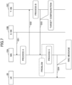
- Fig. 1 is a drawing illustrating a configuration example of a network architecture according to an embodiment of the present invention.
- a radio network architecture in an embodiment of the present invention includes 4G-CU, 4G-RU (Remote Unit, Remote Radio Station), EPC (Evolved Packet Core), etc., on the LTE-Advanced side.
- the radio network architecture in an embodiment of the present invention includes 5G-CU, 5G-DU, etc., on the 5G side.
- the 4G-CU includes layers of RRC (Radio Resource Control), PDCP (Packet Data Convergence Protocol), RLC (Radio Link Control), MAC (Medium Access Control), and L1 (layer 1, PHY layer, or physical layer), and is connected to the 4G-RU via CPRI (Common Public Radio Interface).
- RRC Radio Resource Control
- PDCP Packet Data Convergence Protocol
- RLC Radio Link Control
- MAC Medium Access Control
- L1 layer 1, PHY layer, or physical layer
- the 5G-CU includes an RRC layer, is connected to the 5G-DU through FH (Flonthaul) interface, and is connected to 5GC (5G Core Network) through NG interface.
- the 5G-CU is connected to the 4G-CU through X2 interface.
- the PDCP layer in the 4G-CU is a point of connection or separation in a case where 4G-5G DC (Dual Connectivity), i. e., EN-DC (E-UTRA-NR Dual Connectivity), is performed.
- a network node including the 5G-CU and the 5G-RU is referred to as gNB.
- the 5G-CU may be referred to as gNB-CU
- the 5G-DU may be referred to as gNB-DU.
- CA Carrier Aggregation
- DC is performed via the 4G-RU and the 5G-DU.
- a UE User Equipment
- RF Radio Resource Control
- Fig. 1 illustrates a radio network architecture at the time of LTE-NR DC, i.e., EN-DC (E-UTRA-NR Dual Connectivity).
- EN-DC E-UTRA-NR Dual Connectivity
- the same radio network architecture may be used in a case where the 4G-CU is separated into CU-DU, or in a case where NR standalone operation is performed.
- functions related to an RRC layer and a PDCP may be moved to the 4G-CU, and functions related to an RLC layer and layer(s) therebelow may be included in the 4G-DU.
- the data rate of CPRI may be decreased due to the CU-DU separation.
- eNB in EN-DC may be described as MN (Master Node), and gNB may be described as (Secondary Node).
- a plurality of 5G-DUs may be connected to the 5G-CU.
- NR-DC NR-NR Dual Connectivity
- NR-DC may be performed by connecting the UE to a plurality of 5G-CUs
- NR-DC may be performed by connecting the UE to a plurality of 5G-DUs and a single 5G-CU.
- a 5G-CU may be directly connected to EPC without using a 4G-CU
- a 4G-CU may be directly connected to 5GC without using 5G-CU.
- Fig. 1 indicates, but is not limited to, a radio network architecture at the time of EN-DC.
- the radio network architecture may indicate NR-DC or NE-DC (NR-EUTRA Dual Connectivity), or another radio network architecture may be adopted. Note that the radio network architecture need not be operated by DC, and may be operated standalone.
- Fig. 2 is a drawing illustrating a configuration example of a wireless communication system according to an embodiment of the present invention.
- a wireless communication system according to an embodiment of the present invention includes a base station 10 and a terminal 20.
- a single base station 10 and a single terminal 20 are illustrated as an example.
- the base station 10 is a communication apparatus that provides one or more cells and performs wireless communications with the terminal 20. Physical resources of the radio signal may be defined in the time domain and the frequency domain, the time domain may be defined by the number of OFDM symbols, and the frequency domain may be defined by the number of sub-carriers or resource blocks.
- the base station 10 transmits a synchronization signal and system information to the terminal 20.
- the synchronization signal is, for example, an NR-PSS and an NR-SSS.
- the system information is transmitted via, for example, a NR-PBCH, and may be referred to as broadcast information. As shown in Fig.
- the base station 10 transmits a control signal or data in DL (Downlink) to the terminal 20 and receives a control signal or data in UL (Uplink) from the terminal 20.
- the base station 10 and terminal 20 are capable of transmitting and receiving a signal by performing the beamforming. Further, the base station 10 and the terminal 20 can both apply MIMO (Multiple Input Multiple Output) communication to DL or UL. Further, both the base station 10 and terminal 20 may perform communications via an SCell (Secondary Cell) and a PCell (Primary Cell) using CA (Carrier Aggregation).
- SCell Secondary Cell
- PCell Primary Cell
- CA Carrier Aggregation
- the terminal 20 may be a communication apparatus that includes a wireless communication function such as a smart-phone, a mobile phone, a tablet, a wearable terminal, a communication module for M2M (Machine-to-Machine), or the like. As shown in FIG. 2 , the terminal 20 uses various communication services provided by the wireless communication system by receiving control signals or data in DL from the base station 10 and transmitting control signals or data in UL to the base station 10.
- a wireless communication function such as a smart-phone, a mobile phone, a tablet, a wearable terminal, a communication module for M2M (Machine-to-Machine), or the like.
- M2M Machine-to-Machine
- CPA Conditional PSCell addition
- the CPA is a function of autonomously performing SN addition in a case where the terminal 20 determines that the SN addition execution condition is satisfied by configuring the SN (Secondary node) addition in advance in the network.
- the CPA allows the SN to be configured faster than the conventional technique.
- CPC Conditional PSCell Change
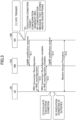
- Fig. 3 is a sequence diagram illustrating an example (1) of an SN change.
- the CPC trigger occurs, and [2] an RRC reconfiguration, which stores the execution condition and the target configuration, is generated.
- the execution condition is a configuration in which how and which frequency is to be measured, and which condition is to be satisfied for performing CPC, are configured.
- the target configuration is a target PSCell configuration, and is a configuration to be configured in a case where the terminal 20 determines to perform.
- step S11 the SN 10B transmits the RRC reconfiguration message including the above-described execution condition and the target configuration, "SgNB modification required” , i.e., "SgNB change request" to the MN 10A.
- step S12 the MN 10A transmits "RRC Connection Reconfiguration” or “RRC reconfiguration” , i.e., "RRC connection reconfiguration” to the terminal 20.
- the UE 20 transmits "RRC Connection Reconfiguration Complete” or “RRC reconfiguration complete” , i. e. , "RRC connection reconfiguration complete” to the MN 10A.
- the MN 10A transmits "SgNB modification confirmed” , i.e., "SgNB change confirmation" to the SN 10B.
- the UE 20 evaluates [3] the execution condition, based on the "RRC Connection Reconfiguration” or “RRC reconfiguration” .
- [4] the execution condition is satisfied, in step S15, "Random Access Procedure” , i.e., "random access procedure” is performed with respect to the SN 10B.
- the terminal 20 After completion of the random access procedure, the terminal 20 performs communication to which dual connectivity is applied, via PSCell after the change under the SN 10B and PCell under the MN 10A.
- the SN initiated inter-SN CPC specified in Release 17 there are a MN, a source SN (hereinafter, also referred to as S-SN), and a target SN (hereinafter, also referred to as T-SN), and thus, discussions are being held on which node is to create which configuration.
- S-SN source SN
- T-SN target SN
- the addition-target PSCell candidates or change-destination PSCell candidates are configured by the network, and the terminal 20 determines which PSCell to be changed to, and thus, there is a possibility that the network performs configurations in advance for a plurality of PSCells.
- a single SN will be described.
- the single SN described below may be replaced with multiple SNs that perform the same operations.
- the process A illustrated in each figure is a process of creating an execution condition.
- the process B illustrated in each figure is a process of creating a target PSCell configuration.
- the process C illustrated in each figure is a process of creating an RRC message including a conditional PSCell configuration by merging the execution condition and the target PSCell configuration.
- an inter-node message in each figure is a message for storing an execution condition, a target PSCell configuration, or an RRC message (for example, RRC reconfiguration) in an existing message such as SgNB addition request or a similar new message, to be indicated.
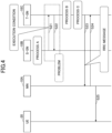
- Fig. 4 is a sequence diagram illustrating an example (2) of a conditional SN change.
- a process A is performed in S-SN 10B.
- the S-SN 10B transmits an execution condition to T-SN 10C.
- the T-SN 10C transmits a response to the S-SN 10B, performs a process B and a process C, and creates an RRC message.
- the T-SN 10C transmits the created RRC message to MN 10A.
- the MN 10A transmits a response to the T-SN 10C.
- the MN 10A realizes CPC by transmitting the RRC message to UE 20.
- the inter-SN messages in steps S21 and S22 require a new interface to be specified, and thus, there is a problem with a significant impact on the signaling in which new messages are to be specified.
- a physical link must be developed for the CPC function alone.
- the specifications of the link need to be developed.
- the number of nodes to communicate increases, the scale of vendor development increases and the cost increases.
- SCTP Stream Control Transmission Protocol
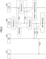
- Fig. 5 is a sequence diagram illustrating an example (3) of a conditional SN change.
- a process A is performed in S-SN 10B.
- the S-SN 10B transmits a request for creating the target configuration to T-SN 10C.
- the T-SN 10C performs the process B.
- the T-SN 10C transmits the target configuration to S-SN 10B.
- the S-SN 10B performs the process C and creates an RRC message.
- the S-SN 10B transmits the created RRC message to MN 10A.
- the MN 10A transmits a response to the S-SN 10B.
- the MN 10A realizes CPC by transmitting the RRC message to UE 20.
- steps S31 and S32 require a new interface to be specified, and thus, there is a problem with a significant impact on the signaling in which new messages are to be specified.
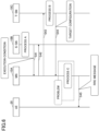
- Fig. 6 is a sequence diagram illustrating an example (4) of a conditional SN change.
- a process A is performed in S-SN 10B.
- the S-SN 10B transmits an execution condition to MN 10A.
- the MN 10A transmits a response to the S-SN 10B.
- the MN 10A transmits a request for creating the target configuration to T-SN 10C.
- the T-SN 10C performs the process B.
- the T-SN 10C transmits the target configuration to the MN 10A.
- the MN 10A performs the process C and creates an RRC message.
- the MN 10A realizes CPC by transmitting the RRC message to UE 20.
- the MN 10A needs to create an RRC message for performing the conditional PSCell reconfiguration.
- the MN 10A as eNB needs to configure the NR RRC reconfiguration, based on the NR configuration created by the S-SN 10B and the T-SN 10, that is, the execution condition and the target configuration. Therefore, there is a problem in that the eNB must create an NR RRC message.
- Fig. 7 is a sequence diagram illustrating an example (5) of a conditional SN change.
- the S-SN 10B transmits, to the MN 10A, a request for starting a process related to CPC.
- a process A is performed in the MN 10A.
- the MN 10A transmits a request for creating the target configuration to T-SN 10C.
- the T-SN 10C performs the process B.
- the T-SN 10C transmits the target configuration to the MN 10A.
- the MN 10A performs the process C and creates an RRC message.
- the MN 10A realizes CPC by transmitting the RRC message to UE 20.
- the MN 10A needs to create an RRC message for performing the conditional PSCell reconfiguration.
- the MN 10A as eNB needs to configure the NR RRC reconfiguration based on the NR configuration created by the S-SN 10B and the T-SN 10C, that is, the execution condition and the target configuration. Therefore, there is a problem in that the eNB must create an NR RRC message.
- Fig. 8 is a sequence diagram illustrating an example (1) of a conditional SN change in an embodiment of the present invention.
- a process A is performed in S-SN 10B.
- the S-SN 10B transmits an execution condition to MN 10A.
- the MN 10A transmits a response to the S-SN 10B.
- the MN 10A transfers the execution condition to the T-SN 10C.
- the T-SN 10C performs the process B and further performs the process C.
- the T-SN 10C transmits the created RRC message to the MN 10A.
- the MN 10A realizes CPC by transmitting an RRC message including the RRC message created by the T-SN 10C to UE 20.
- the interface between the S-SN and the T-SN needs not be specified.
- the MN needs not to create an RRC message of conditional PSCell reconfiguration, and only needs to transfer the received RRC message.
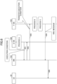
- Fig. 9 is a sequence diagram illustrating an example (2) of a conditional SN change in an embodiment of the present invention.
- a process A is performed in S-SN 10B.
- the S-SN 10B transmits an execution condition to MN 10A.
- the MN 10A transfers the execution condition to T-SN 10C.
- the T-SN 10C performs the process B and further performs the process C.
- the T-SN 10C transmits the created RRC message to the MN 10A.
- the MN 10A transmits a response to the S-SN 10B.
- the MN 10A realizes CPC by transmitting an RRC message including the RRC message created by the T-SN 10C to UE 20.
- the MN can indicate the rejection by the S-SN in step S74, and thus, the call flow can be realized with decreased messages that are one message less than that of the call flow illustrated in Fig. 8 .
- the UE 20 may perform the random access procedure with respect to the T-SN 10C.
- the message which is used by the MN for indicating the configuration to the UE, may be an existing message (for example, RRC reconfiguration, RRC Connection Reconfiguration), or a new RRC message.
- the gNB which transmits an RRC message including the execution condition, the target PSCell configuration or the conditional PSCell configuration, may be a single node or may be multiple nodes in a case where there are multiple candidates.
- a message may be transmitted for each PSCell, or messages may be collectively indicated to a single node.
- the execution condition may be an existing information element (condExecutionCond-r16), or may be a new information element.
- the target PSCell configuration may be an existing information element (condRRCReconfig-r16), or may be a new information element.
- the conditional PSCell configuration may be an existing information element (ConditionalReconfiguration-R16) to be included in an existing message (RRC reconfiguration), may be a new information element, or may be included in a new message.
- the terminal 20 can realize CPC without requiring the message exchange between the SNs and without requiring the RRC message creation by the MN.
- CPC Conditional PSCell Change
- the base station 10 and terminal 20 include functions for implementing the embodiments described above. It should be noted, however, that each of the base stations 10 and the terminal 20 may include only some of the functions in an embodiment.
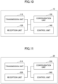
- Fig. 10 is a drawing illustrating an example of a functional structure of a base station 10 according to an embodiment of the present invention.
- the base station 10 includes a transmission unit 110, a reception unit 120, a configuration unit 130, and a control unit 140.
- the functional structure illustrated in Fig. 10 is merely an example. Functional divisions and names of functional units may be anything as long as operations according to an embodiment of the present invention can be performed.
- the transmission unit 110 includes a function for generating a signal to be transmitted to the terminal 20 side and transmitting the signal wirelessly. Further, the transmission unit 110 transmits an inter-network-node message to another network node.
- the reception unit 120 includes a function for receiving various signals transmitted from the terminal 20 and acquiring, for example, information of a higher layer from the received signals. Further, the transmission unit 110 has a function to transmit NR-PSS, NR-SSS, NR-PBCH, DL/UL control signals, and the like to the terminal 20. Further, the reception unit 120 receives an inter-network-node message from another network node.
- the configuration unit 130 stores preset information and various configuration information items to be transmitted to the terminal 20.
- Contents of the configuration information are, for example, information related to the dual connectivity configuration of the terminal 20.
- the control unit 140 performs control related to processing of the dual connectivity as described in the embodiments. Further, the control unit 140 controls communications with the terminal 20 based on the radio-parameter-related UE capability report that is received from the UE 20.
- the functional units related to signal transmission in the control unit 140 may be included in the transmission unit 110, and the functional units related to signal reception in the control unit 140 may be included in the reception unit 120.
- Fig. 11 is a drawing illustrating an example of a functional structure of a terminal 20 according to an embodiment of the present invention.
- the terminal 20 includes a transmission unit 210, a reception unit 220, a configuration unit 230, and a control unit 240.
- the functional structure illustrated in Fig. 11 is merely an example. Functional divisions and names of functional units may be anything as long as operations according to an embodiment of the present invention can be performed.
- the transmission unit 210 generates a transmission signal from transmission data and transmits the transmission signal wirelessly.
- the reception unit 220 receives various signals wirelessly and obtains upper layer signals from the received physical layer signals. Further, the reception unit 220 has a function for receiving NR-PSS, NR-SSS, NR-PBCH, DL/UL/SL control signals, etc., transmitted from the base station 10.
- the transmission unit 210 transmits, to another terminal 20, PSCCH (Physical Sidelink Control Channel), PSSCH (Physical Sidelink Shared Channel), PSDCH (Physical Sidelink Discovery Channel), PSBCH (Physical Sidelink Broadcast Channel), etc., and the reception unit 120 receives, from another terminal 20, PSCCH, PSSCH, PSDCH, or PSBCH.
- PSCCH Physical Sidelink Control Channel
- PSSCH Physical Sidelink Shared Channel
- PSDCH Physical Sidelink Discovery Channel
- PSBCH Physical Sidelink Broadcast Channel
- the configuration unit 230 stores various configuration information items received by the reception unit 220 from the base station 10. In addition, the configuration unit 230 stores pre-configured configuration information. Contents of the configuration information are, for example, information related to the dual connectivity configuration.
- the control unit 240 performs control related to the dual connectivity as described in the embodiments.
- the functional units related to signal transmission in the control unit 240 may be included in the transmission unit 210, and the functional units related to signal reception in the control unit 240 may be included in the reception unit 220.
- each functional block is realized by a freely-selected combination of hardware and/or software. Further, realizing means of each functional block is not limited in particular. In other words, each functional block may be realized by a single apparatus in which multiple elements are coupled physically and/or logically, or may be realized by two or more apparatuses that are physically and/or logically separated and are physically and/or logically connected (e.g., wired and/or wireless).
- the functional blocks may be realized by combining the above-described one or more apparatuses with software.
- Functions include, but are not limited to, judging, determining, calculating, processing, deriving, investigating, searching, checking, receiving, transmitting, outputting, accessing, resolving, selecting, establishing, comparing, assuming, expecting, and deeming; broadcasting, notifying, communicating, forwarding, configuring, reconfiguring, allocating, mapping, and assigning, etc.
- a functional block (component) that functions to transmit is called a transmitting unit or a transmitter. In either case, as described above, the implementation method is not particularly limited.
- the base station 10, terminal 20, etc. may function as a computer for processing the radio communication method of the present disclosure.
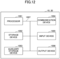
- Fig. 12 is a drawing illustrating an example of hardware structures of the base station 10 and terminal 20 according to an embodiment of the present invention.
- Each of the above-described base station 10 and the terminal 20 may be physically a computer device including a processor 1001, a storage device 1002, an auxiliary storage device 1003, a communication device 1004, an input device 1005, an output device 1006, a bus 1007, etc.
- the term "apparatus” can be read as a circuit, a device, a unit, etc.
- the hardware structures of the base station 10 and terminal 20 may include one or more of each of the devices illustrated in the figure, or may not include some devices.
- Each function in the base station 10 and terminal 20 is realized by having the processor 1001 perform an operation by reading predetermined software (programs) onto hardware such as the processor 1001 and the storage device 1002, and by controlling communication by the communication device 1004 and controlling at least one of reading and writing of data in the storage device 1002 and the auxiliary storage device 1003.
- predetermined software programs
- the communication device 1004 controlling at least one of reading and writing of data in the storage device 1002 and the auxiliary storage device 1003.
- the processor 1001 controls the entire computer by, for example, controlling the operating system.
- the processor 1001 may include a central processing unit (CPU) including an interface with a peripheral apparatus, a control apparatus, a calculation apparatus, a register, etc.
- CPU central processing unit
- control unit 140, control unit 240, and the like may be implemented by the processor 1001.
- the processor 1001 reads out onto the storage device 1002 a program (program code), a software module, or data from the auxiliary storage device 1003 and/or the communication device 1004, and performs various processes according to the program, the software module, or the data.
- a program is used that causes the computer to perform at least a part of operations according to an embodiment of the present invention described above.
- the control unit 140 of the base station 10 illustrated in Fig. 10 may be realized by control programs that are stored in the storage device 1002 and are executed by the processor 1001.
- the control unit 240 of the terminal 20 illustrated in Fig. 11 may be realized by control programs that are stored in the storage device 1002 and are executed by the processor 1001.
- the various processes have been described to be performed by a single processor 1001. However, the processes may be performed by two or more processors 1001 simultaneously or sequentially.
- the processor 1001 may be implemented by one or more chips. It should be noted that the program may be transmitted from a network via a telecommunication line.
- the storage device 1002 is a computer-readable recording medium, and may include at least one of a ROM (Read Only Memory), an EPROM (Erasable Programmable ROM), an EEPROM (Electrically Erasable Programmable ROM), a RAM (Random Access Memory), etc.
- the storage device 1002 may be referred to as a register, a cache, a main memory, etc.
- the storage device 1002 is capable of storing programs (program codes), software modules, or the like, that are executable for performing communication processes according to an embodiment of the present invention.
- the auxiliary storage device 1003 is a computer-readable recording medium, and may include at least one of, for example, an optical disk such as a CD-ROM (Compact Disc ROM), a hard disk drive, a flexible disk, a magneto optical disk (e.g., compact disk, digital versatile disk, Blu-ray (registered trademark) disk), a smart card, a flash memory (e. g., card, stick, key drive), a floppy (registered trademark) disk, a magnetic strip, etc.
- the above recording medium may be a database including the storage device 1002 and/or the auxiliary storage device 1003, a server, or any other appropriate medium.
- the communication device 1004 is hardware (transmission and reception device) for communicating with computers via at least one of a wired network and a wireless network, and may be referred to as a network device, a network controller, a network card, a communication module, etc.
- the communication device 1004 may comprise a high frequency switch, duplexer, filter, frequency synthesizer, or the like, for example, to implement at least one of a frequency division duplex (FDD) and a time division duplex (TDD).
- FDD frequency division duplex
- TDD time division duplex
- the transmitting/receiving antenna, the amplifier unit, the transmitting/receiving unit, the transmission line interface, and the like may be implemented by the communication device 1004.
- the transmitting/receiving unit may be physically or logically divided into a transmitting unit and a receiving unit.
- the input device 1005 is an input device that receives an external input (e.g., keyboard, mouse, microphone, switch, button, sensor).
- the output device 1006 is an output device that outputs something to the outside (e.g., display, speaker, LED lamp). It should be noted that the input device 1005 and the output device 1006 may be integrated into a single device (e.g., touch panel).
- the apparatuses including the processor 1001, the storage device 1002, etc. are connected to each other via the bus 1007 used for communicating information.
- the bus 1007 may include a single bus, or may include different buses between the apparatuses.
- each of the base station 10 and terminal 20 may include hardware such as a microprocessor, a digital signal processor (DSP), an ASIC (Application Specific Integrated Circuit), a PLD (Programmable Logic Device), a FPGA (Field Programmable Gate Array), etc., and a part or all of each functional block may be realized by the hardware.
- the processor 1001 may be implemented by at least one of the above hardware elements.
- a base station includes: a reception unit configured to receive, from a source secondary node, a condition for changing a primary secondary cell group cell; and a transmission unit configured to transmit the condition to a target secondary node.
- the reception unit receives, from the target secondary node, a message including the condition and a configuration related to a primary secondary cell group cell after the change, and the transmission unit transmits the message to a terminal.
- the terminal 20 can realize CPC without requiring the message exchange between the SNs and without requiring the RRC message creation by the MN. That is, CPC (Conditional PSCell Change) can be implemented in a simple and useful manner in a wireless communication system.
- the transmission unit may transmit the information indicating the rejection to the source secondary node as a response to the source secondary node that has received the condition.
- a terminal includes: a reception unit configured to receive, from a master node, a message including a condition for changing a primary secondary cell group cell and a configuration related to a primary secondary cell group cell after the change; a control unit configured to determine whether the condition is satisfied; and a transmission unit configured to perform a random access procedure to the primary secondary cell group cell after the change, based on the configuration, in a case where the condition is satisfied, wherein the condition is created by a source secondary node, and the configuration and the message are created by a target secondary node.
- the terminal 20 can realize CPC without requiring the message exchange between the SNs and without requiring the RRC message creation by the MN. That is, CPC (Conditional PSCell Change) can be implemented in a simple and useful manner in a wireless communication system.
- a base station includes: a reception unit configured to receive, from a source secondary node via a master node, a condition for changing a primary secondary cell group cell; a control unit configured to create a message including the condition and a configuration related to a primary secondary cell group cell after the change; and a transmission unit configured to transmit the message to the master node.
- the terminal 20 can realize CPC without requiring the message exchange between the SNs and without requiring the RRC message creation by the MN. That is, CPC (Conditional PSCell Change) can be implemented in a simple and useful manner in a wireless communication system.
- a communication method performed by a base station includes: receiving, from a source secondary node, a condition for changing a primary secondary cell group cell; transmitting the condition to a target secondary node; receiving, from the target secondary node, a message including the condition and a configuration related to a primary secondary cell group cell after the change; and transmitting the message to a terminal.
- the terminal 20 can realize CPC without requiring the message exchange between the SNs and without requiring the RRC message creation by the MN. That is, CPC (Conditional PSCell Change) can be implemented in a simple and useful manner in a wireless communication system.
- the software executed by a processor included in the base station 10 according to an embodiment of the present invention and the software executed by a processor included in the terminal 20 according to an embodiment of the present invention may be stored in a random access memory (RAM), a flash memory, a read only memory (ROM), an EPROM, an EEPROM, a register, a hard disk (HDD), a removable disk, a CD-ROM, a database, a server, or any other appropriate recording medium.
- RAM random access memory
- ROM read only memory
- EPROM an EPROM
- EEPROM electrically erasable programmable read-only memory
- register a register
- HDD hard disk
- CD-ROM compact disc-read only memory
- database a database
- server or any other appropriate recording medium.
- information indication may be performed not only by methods described in an aspect/embodiment of the present specification but also a method other than those described in an aspect/embodiment of the present specification.
- the information transmission may be performed by physical layer signaling (e.g., DCI (Downlink Control Information), UCI (Uplink Control Information)), upper layer signaling (e.g., RRC (Radio Resource Control) signaling, MAC (Medium Access Control) signaling, broadcast information (MIB (Master Information Block), SIB (System Information Block))), other signals, or combinations thereof.
- RRC signaling may be referred to as an RRC message.
- the RRC signaling may be, for example, an RRC connection setup message, an RRC connection reconfiguration message, or the like.
- Each aspect/embodiment described in the present disclosure may be applied to at least one of a system using LTE (Long Term Evolution), LTE-A (LTE-Advanced), SUPER 3G, IMT-Advanced, 4G (4th generation mobile communication system), 5G (5th generation mobile communication system), FRA (Future Radio Access), NR (new Radio), W-CDMA (registered trademark), GSM (registered trademark), CDMA2000, UMB (Ultra Mobile Broadband), IEEE 802.11 (Wi-Fi (registered trademark)), IEEE 802.16 (WiMAX (registered trademark)), IEEE 802.20, UWB (Ultra-WideBand), Bluetooth (registered trademark), and other appropriate systems, and a next generation system enhanced therefrom. Further, multiple systems may also be applied in combination (e.g., at least one of LTE and LTE-A combined with 5G, etc.).
- the particular operations, that are supposed to be performed by the base station 10 in the present specification, may be performed by an upper node in some cases.
- a network including one or more network nodes including the base station 10 it is apparent that various operations performed for communicating with the terminal 20 may be performed by the base station 10 and/or another network node other than the base station 10 (for example, but not limited to, MME or S-GW).
- MME Mobility Management Entity
- S-GW network node
- a combination of multiple other network nodes may be considered (e.g., MME and S-GW).
- the information or signals described in this disclosure may be output from a higher layer (or lower layer) to a lower layer (or higher layer).
- the information or signals may be input or output through multiple network nodes.
- the input or output information may be stored in a specific location (e.g., memory) or managed using management tables.
- the input or output information may be overwritten, updated, or added.
- the information that has been output may be deleted.
- the information that has been input may be transmitted to another apparatus.
- a decision or a determination in an embodiment of the present invention may be realized by a value (0 or 1) represented by one bit, by a boolean value (true or false), or by comparison of numerical values (e.g., comparison with a predetermined value).
- Software should be broadly interpreted to mean, whether referred to as software, firmware, middle-ware, microcode, hardware description language, or any other name, instructions, instruction sets, codes, code segments, program codes, programs, subprograms, software modules, applications, software applications, software packages, routines, subroutines, objects, executable files, executable threads, procedures, functions, and the like.
- software, instructions, information, and the like may be transmitted and received via a transmission medium.
- a transmission medium such as coaxial cable, fiber optic cable, twisted pair, digital subscriber line (DSL)
- wired line technologies such as coaxial cable, fiber optic cable, twisted pair, digital subscriber line (DSL)
- wireless technologies infrared, microwave, etc.
- Information, a signal, or the like, described in the present specification may be represented by using any one of various different technologies.
- data, an instruction, a command, information, a signal, a bit, a symbol, a chip, or the like, described throughout the present application may be represented by a voltage, an electric current, electromagnetic waves, magnetic fields, a magnetic particle, optical fields, a photon, or a combination thereof.
- a channel and/or a symbol may be a signal (signaling).
- a signal may be a message.
- the component carrier CC may be referred to as a carrier frequency, cell, frequency carrier, or the like.
- system and “network” are used interchangeably.
- a radio resource may be what is indicated by an index.
- BS Base Station
- Radio Base Station Base Station
- Base Station Apparatus Fixed Station
- NodeB NodeB
- eNodeB eNodeB
- gNodeB gNB
- Access Point "Transmission Point”
- Reception Point Transmission/Reception Point
- Cell Cell
- Sector Cell Group
- Carrier Carrier
- Component Carrier and the like
- the base station may be referred to as a macro-cell, a small cell, a femtocell, a picocell and the like.
- the base station may accommodate (provide) one or more (e. g. , three) cells.
- the entire coverage area of the base station may be divided into a plurality of smaller areas, each smaller area may provide communication services by means of a base station subsystem (e.g., an indoor small base station or a remote Radio Head (RRH)).
- a base station subsystem e.g., an indoor small base station or a remote Radio Head (RRH)
- RRH remote Radio Head
- the term "cell” or “sector” refers to a part or all of the coverage area of at least one of the base station and base station subsystem that provides communication services at the coverage.
- MS mobile station
- UE user equipment
- terminal terminal
- the mobile station may be referred to, by a person skilled in the art, as a subscriber station, a mobile unit, a subscriber unit, a wireless unit, a remote unit, a mobile device, a wireless device, a wireless communication device, a remote device, a mobile subscriber station, an access terminal, a mobile terminal, a wireless terminal, a remote terminal, a handset, a user agent, a mobile client, a client, or some other appropriate terms.
- At least one of the base station and the mobile station may be referred to as a transmission apparatus, reception apparatus, communication apparatus, or the like.
- the at least one of the base station and the mobile station may be a device mounted on the mobile station, the mobile station itself, or the like.
- the mobile station may be a vehicle (e.g., a car, an airplane, etc.), an unmanned mobile body (e.g., a drone, an automated vehicle, etc.), or a robot (manned or unmanned).
- At least one of the base station and the mobile station may include an apparatus that does not necessarily move during communication operations.
- at least one of the base station and the mobile station may be an IoT (Internet of Things) device such as a sensor.
- IoT Internet of Things
- the base station in the present disclosure may be read as the user terminal.
- each aspect/embodiment of the present disclosure may be applied to a configuration in which communications between the base station and the user terminal are replaced by communications between multiple terminals 20 (e.g., may be referred to as D2D (Device-to-Device), V2X (Vehicle-to-Everything), etc.).
- the function of the base station 10 described above may be provided by the terminal 20.
- the phrases "up” and “down” may also be replaced by the phrases corresponding to terminal-to-terminal communication (e.g., "side").
- an uplink channel, a downlink channel, or the like may be read as a sidelink channel.
- the user terminal in the present disclosure may be read as the base station.
- the function of the user terminal described above may be provided by the base station.
- the term "determining” used in the present specification may include various actions or operations.
- the “determining” may include, for example, a case in which "judging", “calculating”, “computing”, “processing”, “deriving”, “investigating”, “looking up, search, inquiry” (e.g., looking up a table, database, or other data structures), or “ascertaining” is deemed as “determining”.
- the “determining” may include a case in which “receiving” (e.g., receiving information), “transmitting” (e.g., transmitting information), “inputting", “outputting”, or “accessing” (e.g., accessing data in a memory) is deemed as “determining”.
- the "determining” may include a case in which “resolving”, “selecting”, “choosing”, “establishing”, “comparing”, or the like is deemed as “determining”.
- the “determining” may include a case in which a certain action or operation is deemed as “determining”.
- “determining” may be read as “assuming", “expecting”, or “considering”, etc.
- connection means any direct or indirect connection or connection between two or more elements and may include the presence of one or more intermediate elements between the two elements “connected” or “coupled” with each other.
- the coupling or connection between the elements may be physical, logical, or a combination thereof.
- connection may be read as "access”.
- the two elements may be thought of as being “connected” or “coupled” to each other using at least one of the one or more wires, cables, and printed electrical connections and, as a number of non-limiting and non-inclusive examples, electromagnetic energy having wavelengths in the radio frequency region, the microwave region, and the light (both visible and invisible) region.
- the reference signal may be abbreviated as RS or may be referred to as a pilot, depending on the applied standards.
- references to an element using terms such as "first” or “second” as used in the present disclosure does not generally limit the amount or the order of those elements. These terms may be used in the present disclosure as a convenient way to distinguish between two or more elements. Therefore, references to the first and second elements do not imply that only two elements may be employed or that the first element must in some way precede the second element.
- a radio frame may include one or more frames in the time domain.
- Each of the one or more frames in the time domain may be referred to as a subframe.
- the subframe may further include one or more slots in the time domain.
- the subframe may be a fixed length of time (e.g., 1 ms) independent from the numerology.
- the numerology may be a communication parameter that is applied to at least one of the transmission and reception of a signal or channel.
- the numerology may indicate at least one of, for example, SubCarrier Spacing (SCS), bandwidth, symbol length, cyclic prefix length, transmission time interval (TTI), number of symbols per TTI, radio frame configuration, specific filtering processing performed by the transceiver in the frequency domain, and specific windowing processing performed by the transceiver in the time domain.
- SCS SubCarrier Spacing
- TTI transmission time interval
- radio frame configuration specific filtering processing performed by the transceiver in the frequency domain
- specific windowing processing performed by the transceiver in the time domain specific windowing processing performed by the transceiver in the time domain.
- the slot may include one or more symbols in the time domain, such as OFDM (Orthogonal Frequency Division Multiplexing) symbols, SC-FDMA (Single Carrier Frequency Division Multiple Access) symbols, and the like.
- the slot may be a time unit based on the numerology.
- the slot may include a plurality of mini slots. Each mini slot may include one or more symbols in the time domain. Further, the mini slot may be referred to as a sub-slot. The mini slot may include fewer symbols than the slot.
- PDSCH (or PUSCH) transmitted in time units greater than a mini slot may be referred to as PDSCH (or PUSCH) mapping type A.
- PDSCH (or PUSCH) transmitted using a mini slot may be referred to as PDSCH (or PUSCH) mapping type B.
- a radio frame, a subframe, a slot, a mini slot and a symbol all represent time units for transmitting signals. Different terms may be used for referring to a radio frame, a subframe, a slot, a mini slot and a symbol, respectively.
- one subframe may be referred to as a transmission time interval (TTI)
- TTI transmission time interval
- multiple consecutive subframes may be referred to as a TTI
- one slot or one mini slot may be referred to as a TTI.
- at least one of the subframe and the TTI may be a subframe (1 ms) in an existing LTE, a period shorter than 1 ms (e.g., 1-13 symbols), or a period longer than 1 ms.
- the unit representing the TTI may be referred to as a slot, a mini slot, or the like, rather than a subframe.
- the TTI refers to, for example, the minimum time unit for scheduling in wireless communications.
- a base station schedules each terminal 20 to allocate radio resources (such as frequency bandwidth, transmission power, etc. that can be used in each terminal 20) in TTI units.
- radio resources such as frequency bandwidth, transmission power, etc. that can be used in each terminal 20.
- the definition of TTI is not limited to the above.
- the TTI may be a transmission time unit, such as a channel-encoded data packet (transport block), code block, codeword, or the like, or may be a processing unit, such as scheduling or link adaptation. It should be noted that, when a TTI is provided, the time interval (e.g., the number of symbols) during which the transport block, code block, codeword, or the like, is actually mapped may be shorter than the TTI.
- one or more TTIs may be the minimum time unit for scheduling. Further, the number of slots (the number of mini slots) constituting the minimum time unit of the scheduling may be controlled.
- a TTI having a time length of 1 ms may be referred to as a normal TTI (a TTI in LTE Rel. 8-12), a long TTI, a normal subframe, a long subframe, a slot, and the like.
- a TTI that is shorter than the normal TTI may be referred to as a shortened TTI, a short TTI, a partial TTI (or fractional TTI), a shortened subframe, a short subframe, a mini slot, a subslot, a slot, or the like.
- the long TTI e.g., normal TTI, subframe, etc. may be replaced with a TTI having a time length exceeding 1 ms
- the short TTI e.g., shortened TTI, etc., may be replaced with a TTI having a TTI length less than the TTI length of the long TTI and a TTI length greater than 1 ms.
- a resource block is a time domain and frequency domain resource allocation unit and may include one or more consecutive subcarriers in the frequency domain.
- the number of subcarriers included in a RB may be the same, regardless of the numerology, and may be 12, for example.
- the number of subcarriers included in an RB may be determined based on the numerology.
- the time domain of a RB may include one or more symbols, which may be 1 slot, 1 mini slot, 1 subframe, or 1 TTI in length.
- One TTI, one subframe, etc. may each include one or more resource blocks.
- one or more RBs may be referred to as physical resource blocks (PRBs, Physical RBs), sub-carrier groups (SCGs), resource element groups (REGs), PRB pairs, RB pairs, and the like.
- PRBs physical resource blocks
- SCGs sub-carrier groups
- REGs resource element groups
- PRB pairs RB pairs, and the like.
- a resource block may include one or more resource elements (RE).
- RE resource elements
- 1 RE may be a radio resource area of one sub-carrier and one symbol.
- the bandwidth part (which may also be referred to as a partial bandwidth, etc.) may represent a subset of consecutive common RBs (common resource blocks) for a given numerology in a carrier.
- a common RB may be identified by an index of RB relative to the common reference point of the carrier.
- a PRB may be defined in a BWP and may be numbered within the BWP.
- BWP may include BWP for UL (UL BWP) and BWP for DL (DL BWP).
- BWP for a UE, one or more BWPs may be configured in one carrier.
- At least one of the configured BWPs may be activated, and the UE may assume that the UE will not transmit and receive signals/channels outside the activated BWP. It should be noted that the terms “cell” and “carrier” in this disclosure may be replaced by "BWP.”
- Structures of a radio frame, a subframe, a slot, a mini slot, and a symbol described above are exemplary only.
- the number of subframes included in a radio frame, the number of slots per subframe or radio frame, the number of mini slots included in a slot, the number of symbols and RBs included in a slot or mini slot, the number of subcarriers included in a RB, the number of symbols in a TTI, the symbol length, the cyclic prefix (CP) length, and the like may be changed in various ways.
- the term "A and B are different” may mean “A and B are different from each other.” It should be noted that the term “A and B are different” may mean “A and B are different from C.” Terms such as “separated” or “combined” may be interpreted in the same way as the above-described "different”.
- notification (transmission/reporting) of predetermined information is not limited to an explicit notification (transmission/reporting), and may be performed by an implicit notification (transmission/reporting) (e.g., by not performing notification (transmission/reporting) of the predetermined information).
- the execution condition is an example of a condition for changing the primary secondary cell group cell.
- the target configuration or the target PSCell configuration is an example of a configuration related to the primary secondary cell group cell after the change.
Landscapes
- Engineering & Computer Science (AREA)
- Computer Networks & Wireless Communication (AREA)
- Signal Processing (AREA)
- Mobile Radio Communication Systems (AREA)
Applications Claiming Priority (1)
| Application Number | Priority Date | Filing Date | Title |
|---|---|---|---|
| PCT/JP2020/040155 WO2022091191A1 (ja) | 2020-10-26 | 2020-10-26 | 基地局、端末及び通信方法 |
Publications (2)
| Publication Number | Publication Date |
|---|---|
| EP4236418A1 true EP4236418A1 (de) | 2023-08-30 |
| EP4236418A4 EP4236418A4 (de) | 2024-07-24 |
Family
ID=81382159
Family Applications (1)
| Application Number | Title | Priority Date | Filing Date |
|---|---|---|---|
| EP20959709.5A Withdrawn EP4236418A4 (de) | 2020-10-26 | 2020-10-26 | Basisstation, endgerät und kommunikationsverfahren |
Country Status (2)
| Country | Link |
|---|---|
| EP (1) | EP4236418A4 (de) |
| WO (1) | WO2022091191A1 (de) |
Families Citing this family (1)
| Publication number | Priority date | Publication date | Assignee | Title |
|---|---|---|---|---|
| WO2024187318A1 (zh) * | 2023-03-10 | 2024-09-19 | 深圳传音控股股份有限公司 | 配置方法、通信设备及存储介质 |
-
2020
- 2020-10-26 EP EP20959709.5A patent/EP4236418A4/de not_active Withdrawn
- 2020-10-26 WO PCT/JP2020/040155 patent/WO2022091191A1/ja not_active Ceased
Also Published As
| Publication number | Publication date |
|---|---|
| WO2022091191A1 (ja) | 2022-05-05 |
| EP4236418A4 (de) | 2024-07-24 |
Similar Documents
| Publication | Publication Date | Title |
|---|---|---|
| EP4017161A1 (de) | Endgerät und kommunikationsverfahren | |
| US12452841B2 (en) | Base station, terminal and communication method for performing dual connectivity (DC) in multiple radio access technologies (RAT) | |
| EP4132130A1 (de) | Endgerät und kommunikationsverfahren | |
| EP3883282A1 (de) | Benutzergerät und basisstationsvorrichtung | |
| EP4057760A1 (de) | Endgerät und kommunikationsverfahren | |
| CN114982262A (zh) | 终端、基站以及通信方法 | |
| US12477527B2 (en) | Terminal, base station and communication method | |
| JP7847185B2 (ja) | 基地局、通信システム及び通信方法 | |
| JPWO2020161907A1 (ja) | ユーザ装置 | |
| EP4236510A1 (de) | Endgerät und kommunikationsverfahren | |
| EP3930393B1 (de) | Benutzervorrichtung und basisstationsvorrichtung | |
| EP4236418A1 (de) | Basisstation, endgerät und kommunikationsverfahren | |
| US12610376B2 (en) | Terminal, communication method, base station, and wireless system for scheduling transmission of a plurality of channels | |
| JP7373559B2 (ja) | ユーザ装置及び無線通信システム | |
| EP4351196A1 (de) | Endgerät und kommunikationsverfahren | |
| US12232175B2 (en) | User apparatus and base station apparatus | |
| EP4017061A1 (de) | Endgerät, basisstationsvorrichtung und kommunikationsverfahren | |
| EP4040822A1 (de) | Endgerät und kommunikationsverfahren | |
| US11889366B2 (en) | Base station for transmission of message between base stations and communication method performed by base station | |
| US20240259784A1 (en) | Terminal and communication method | |
| EP4344320A1 (de) | Endgerät und kommunikationsverfahren | |
| EP4340489A1 (de) | Endgerät und kommunikationsverfahren | |
| EP4304265A1 (de) | Endgerät und kommunikationsverfahren | |
| EP4340425A1 (de) | Endgerät und kommunikationsverfahren | |
| EP4236527A1 (de) | Endgerät und kommunikationsverfahren |
Legal Events
| Date | Code | Title | Description |
|---|---|---|---|
| STAA | Information on the status of an ep patent application or granted ep patent |
Free format text: STATUS: THE INTERNATIONAL PUBLICATION HAS BEEN MADE |
|
| PUAI | Public reference made under article 153(3) epc to a published international application that has entered the european phase |
Free format text: ORIGINAL CODE: 0009012 |
|
| STAA | Information on the status of an ep patent application or granted ep patent |
Free format text: STATUS: REQUEST FOR EXAMINATION WAS MADE |
|
| 17P | Request for examination filed |
Effective date: 20230328 |
|
| AK | Designated contracting states |
Kind code of ref document: A1 Designated state(s): AL AT BE BG CH CY CZ DE DK EE ES FI FR GB GR HR HU IE IS IT LI LT LU LV MC MK MT NL NO PL PT RO RS SE SI SK SM TR |
|
| DAV | Request for validation of the european patent (deleted) | ||
| DAX | Request for extension of the european patent (deleted) | ||
| A4 | Supplementary search report drawn up and despatched |
Effective date: 20240624 |
|
| RIC1 | Information provided on ipc code assigned before grant |
Ipc: H04W 36/00 20090101ALI20240619BHEP Ipc: H04W 92/20 20090101ALI20240619BHEP Ipc: H04W 92/10 20090101ALI20240619BHEP Ipc: H04W 72/04 20230101ALI20240619BHEP Ipc: H04W 36/28 20090101ALI20240619BHEP Ipc: H04W 16/32 20090101AFI20240619BHEP |
|
| STAA | Information on the status of an ep patent application or granted ep patent |
Free format text: STATUS: THE APPLICATION IS DEEMED TO BE WITHDRAWN |
|
| 18D | Application deemed to be withdrawn |
Effective date: 20250114 |