EP4236350A1 - Integrated loudspeaker assembly - Google Patents
Integrated loudspeaker assembly Download PDFInfo
- Publication number
- EP4236350A1 EP4236350A1 EP23157753.7A EP23157753A EP4236350A1 EP 4236350 A1 EP4236350 A1 EP 4236350A1 EP 23157753 A EP23157753 A EP 23157753A EP 4236350 A1 EP4236350 A1 EP 4236350A1
- Authority
- EP
- European Patent Office
- Prior art keywords
- loudspeaker
- grille
- enclosure
- assembly
- integrated
- Prior art date
- Legal status (The legal status is an assumption and is not a legal conclusion. Google has not performed a legal analysis and makes no representation as to the accuracy of the status listed.)
- Granted
Links
Images





Classifications
-
- H—ELECTRICITY
- H04—ELECTRIC COMMUNICATION TECHNIQUE
- H04R—LOUDSPEAKERS, MICROPHONES, GRAMOPHONE PICK-UPS OR LIKE ACOUSTIC ELECTROMECHANICAL TRANSDUCERS; ELECTRIC HEARING AIDS; PUBLIC ADDRESS SYSTEMS
- H04R1/00—Details of transducers, loudspeakers or microphones
- H04R1/02—Casings; Cabinets ; Supports therefor; Mountings therein
- H04R1/026—Supports for loudspeaker casings
-
- H—ELECTRICITY
- H04—ELECTRIC COMMUNICATION TECHNIQUE
- H04R—LOUDSPEAKERS, MICROPHONES, GRAMOPHONE PICK-UPS OR LIKE ACOUSTIC ELECTROMECHANICAL TRANSDUCERS; ELECTRIC HEARING AIDS; PUBLIC ADDRESS SYSTEMS
- H04R1/00—Details of transducers, loudspeakers or microphones
- H04R1/02—Casings; Cabinets ; Supports therefor; Mountings therein
-
- H—ELECTRICITY
- H04—ELECTRIC COMMUNICATION TECHNIQUE
- H04R—LOUDSPEAKERS, MICROPHONES, GRAMOPHONE PICK-UPS OR LIKE ACOUSTIC ELECTROMECHANICAL TRANSDUCERS; ELECTRIC HEARING AIDS; PUBLIC ADDRESS SYSTEMS
- H04R9/00—Transducers of moving-coil, moving-strip, or moving-wire type
- H04R9/06—Loudspeakers
-
- B—PERFORMING OPERATIONS; TRANSPORTING
- B60—VEHICLES IN GENERAL
- B60R—VEHICLES, VEHICLE FITTINGS, OR VEHICLE PARTS, NOT OTHERWISE PROVIDED FOR
- B60R11/00—Arrangements for holding or mounting articles, not otherwise provided for
- B60R11/02—Arrangements for holding or mounting articles, not otherwise provided for for radio sets, television sets, telephones, or the like; Arrangement of controls thereof
- B60R11/0217—Arrangements for holding or mounting articles, not otherwise provided for for radio sets, television sets, telephones, or the like; Arrangement of controls thereof for loud-speakers
-
- H—ELECTRICITY
- H04—ELECTRIC COMMUNICATION TECHNIQUE
- H04R—LOUDSPEAKERS, MICROPHONES, GRAMOPHONE PICK-UPS OR LIKE ACOUSTIC ELECTROMECHANICAL TRANSDUCERS; ELECTRIC HEARING AIDS; PUBLIC ADDRESS SYSTEMS
- H04R1/00—Details of transducers, loudspeakers or microphones
- H04R1/02—Casings; Cabinets ; Supports therefor; Mountings therein
- H04R1/028—Casings; Cabinets ; Supports therefor; Mountings therein associated with devices performing functions other than acoustics, e.g. electric candles
-
- H—ELECTRICITY
- H04—ELECTRIC COMMUNICATION TECHNIQUE
- H04R—LOUDSPEAKERS, MICROPHONES, GRAMOPHONE PICK-UPS OR LIKE ACOUSTIC ELECTROMECHANICAL TRANSDUCERS; ELECTRIC HEARING AIDS; PUBLIC ADDRESS SYSTEMS
- H04R9/00—Transducers of moving-coil, moving-strip, or moving-wire type
- H04R9/02—Details
-
- H—ELECTRICITY
- H04—ELECTRIC COMMUNICATION TECHNIQUE
- H04R—LOUDSPEAKERS, MICROPHONES, GRAMOPHONE PICK-UPS OR LIKE ACOUSTIC ELECTROMECHANICAL TRANSDUCERS; ELECTRIC HEARING AIDS; PUBLIC ADDRESS SYSTEMS
- H04R1/00—Details of transducers, loudspeakers or microphones
- H04R1/02—Casings; Cabinets ; Supports therefor; Mountings therein
- H04R1/023—Screens for loudspeakers
-
- H—ELECTRICITY
- H04—ELECTRIC COMMUNICATION TECHNIQUE
- H04R—LOUDSPEAKERS, MICROPHONES, GRAMOPHONE PICK-UPS OR LIKE ACOUSTIC ELECTROMECHANICAL TRANSDUCERS; ELECTRIC HEARING AIDS; PUBLIC ADDRESS SYSTEMS
- H04R2400/00—Loudspeakers
- H04R2400/11—Aspects regarding the frame of loudspeaker transducers
-
- H—ELECTRICITY
- H04—ELECTRIC COMMUNICATION TECHNIQUE
- H04R—LOUDSPEAKERS, MICROPHONES, GRAMOPHONE PICK-UPS OR LIKE ACOUSTIC ELECTROMECHANICAL TRANSDUCERS; ELECTRIC HEARING AIDS; PUBLIC ADDRESS SYSTEMS
- H04R2499/00—Aspects covered by H04R or H04S not otherwise provided for in their subgroups
- H04R2499/10—General applications
- H04R2499/13—Acoustic transducers and sound field adaptation in vehicles
Definitions
- aspects disclosed herein generally relate to an integrated loudspeaker assembly.
- the integrated loudspeaker assembly may be used in various automotive applications.
- the disclosed integrated loudspeaker assembly may be used to generate alerts to pedestrians positioned exterior to a vehicle.
- An Approaching Vehicle Alert System generally includes at least one loudspeaker that is positioned on the vehicle to provide alerts to pedestrians when the vehicle is moving in low speeds in an electric mode. Aspects of the AVAS may be mandated by regulation FMVSS141 for an Electric Vehicle (EV)/Plug-In Hybrid Electric Vehicle (PHEV)/Hybrid vehicle.
- the loudspeaker(s) is typically packaged outside of a cabin space of the vehicle in a front and/or rear locations of the vehicle.
- the loudspeakers may be subjected to harsh environment conditions such as extreme temperatures, humidity, water splash, dust, salt, snow, sand exposure, etc.
- current loudspeakers and/or electronic controllers that are electrically coupled to the loudspeakers are packaged in enclosures to protect such loudspeakers and electronic controllers from the environment conditions.
- Current loudspeaker designs may require numerous assembly operations and numerous components to develop and tool.
- current loudspeaker designs may have more water sealing joints and thus provide more leak paths and hence less robust.
- Current loudspeaker designs may be more expensive since there are more components and overall complexity of the assembly process is increased.
- a loudspeaker assembly for attachment to an exterior portion of a vehicle.
- the assembly includes a loudspeaker, a base enclosure, and a grille enclosure.
- the loudspeaker transmits an audio output into an environment that is exterior to the vehicle.
- the base enclosure receives the loudspeaker and includes a first ramped surface formed on an exterior portion thereof.
- the grille enclosure includes an integrated loudspeaker grille to cover the loudspeaker.
- the grille enclosure further includes a second ramped surface positioned on an exterior portion thereof and being positioned directly adjacent to the first ramped surface of the base enclosure when the base enclosure is coupled to the grille enclosure. Each of the first ramped surface and the second ramped surface is non-perpendicular to the integrated loudspeaker grille.
- a loudspeaker assembly for attachment to a vehicle.
- the assembly includes a loudspeaker, a base enclosure, and a grille enclosure.
- the loudspeaker transmits an audio output from the vehicle.
- the base enclosure receives the loudspeaker and includes a first ramped surface formed on an exterior portion thereof.
- the grille enclosure includes an integrated loudspeaker grille to cover the loudspeaker.
- the grille enclosure further includes a second ramped surface on an exterior portion thereof and being positioned adjacent to the first ramped surface of the base enclosure when the base enclosure is coupled to the grille enclosure.
- Each of the first ramped surface and the second ramped surface extend along a non-perpendicular axis relative to the integrated loudspeaker grille.
- a loudspeaker assembly for attachment to a vehicle.
- the assembly includes a loudspeaker, a base enclosure, and a grille enclosure.
- the loudspeaker transmits an audio output from the vehicle.
- the base enclosure receives the loudspeaker and includes a first ramped surface formed thereon.
- the grille enclosure includes an integrated loudspeaker grille to cover the loudspeaker.
- the grille enclosure further includes a second ramped surface formed thereon and being positioned adjacent to the first ramped surface of the base enclosure when the base enclosure is coupled to the grille enclosure.
- Each of the first ramped surface and the second ramped surface extend along a non-perpendicular axis relative to the integrated loudspeaker grille.
- One method to improve reliability and overall quality for the loudspeaker may involve reducing an overall number of components used in constructing the loudspeaker. This approach also reduces the number of components to assemble which inherently reduces overall cost. For example, by combining an outer shell of the enclosure with a speaker grille, such an implementation may reduce components.
- the disclosed loudspeaker provides an enclosure including a speaker grille that are integrated with one another.
- aspects disclosed herein generally provide the loudspeaker grille that is integrated with a portion of the enclosure and another portion that is coupled to the loudspeaker basket that provides a single assembly.
- the disclosed loudspeaker may be scalable to different sizes and may be used with predetermined materials to allow flexibility in vehicle level packaging. OEMs may also require electronic components (e.g., printed circuit board (PCB) assembly) related to AVAS in the same enclosure that houses the loudspeaker.
- the disclosed loudspeaker may be an AVAS based loudspeaker and that outputs an audio signal in response to an audio input provided by a controller.
- the disclosed loudspeaker may utilize adhesives and mechanical snap features to couple two portions of the enclosure together.
- the disclosed loudspeaker may be made watertight and may eliminate one or more gaskets which also reduces cost.
- the two halves may be welded via, for example, vibration welding to provide a tight joint that prevents fluid intrusion.
- a gasket between the two halves with snap features may also be implemented to provide a waterproof assembly.
- FIGUREs 1 and 2 depict one example of a loudspeaker assembly ("the assembly") 100 for an Approaching Vehicle Alert System (AVAS).
- the assembly 100 may be positioned on an exterior portion of a vehicle 101.
- the assembly 100 include a base enclosure 102, a basket enclosure 104, and a loudspeaker grille 106.
- the basket enclosure 104 defines an opening for receiving the loudspeaker grille 106.
- the assembly 100 includes a loudspeaker 108 and a magnetic motor assembly 110.
- the magnetic motor assembly 110 generally includes a voice coil (not shown) and a magnetic core (not shown). As known, the voice coil and the magnetic core enable a cone (or diaphragm) 113 to generally move along a first axis 109 to transmit an audio output signal.
- the loudspeaker 108 may transmit the audio output signal anywhere from 160 to 5000 Hz.
- the basket enclosure 104 includes both a basket 105 that is integrated with an upper portion 107 (or upper half) of the basket enclosure 104.
- the basket 105 and the upper portion 107 are integrated with one another.
- the loudspeaker 108 includes a lead assembly 111 (or lead wires), the cone 113, a surround 115, and a plurality of terminals (not shown).
- the lead assembly 111 electrically couples the loudspeaker 108 to a power source (not shown) and an audio controller (not shown) via the terminals.
- the loudspeaker grille 106 covers the loudspeaker 108 and serves to protect the loudspeaker 108 (e.g., the lead assembly 111, the cone 113, the surround 115, etc.) from direct contact from water or other objects.
- the base enclosure 102 defines an opening 112 for receiving the loudspeaker 108.
- the base enclosure 102 also forms a receiving lip 114 positioned on outer perimeter thereof.
- the receiving lip 114 receives an underside of the basket enclosure 104.
- the receiving lip 114 and the basket enclosure 104 form a water seal to prevent water or other fluid from intruding into the opening 112 and contacting the components that are associated with the loudspeaker 108.
- the assembly 100 does not utilize screws to attach the base enclosure 102 to the basket enclosure 104.
- the base enclosure 102 and the basket enclosure 104 are coupled to one another via adhesive which also serves to seal the joint formed between the base enclosure 102 and the basket enclosure 104.
- the base enclosure 102 also provides a vent (not shown) that enables air to flow through while keeping fluids away from the loudspeaker 108.
- FIGURE 3A depicts a cross-sectional view of the loudspeaker assembly 100 of FIGURE 1 .
- FIGURE 3B depicts a more detailed cross-sectional view of one aspect of the loudspeaker assembly 100 of FIGURE 3A .
- the loudspeaker 108 also includes a spider 117 positioned below the cone 113.
- the surround 115 includes an outer ring 120 that is integrated therewith. The outer ring 120 receives one end of the loudspeaker grille 106. Adhesive is applied to an underside of the surround 115 to attach the loudspeaker 108 to the basket enclosure 104.
- Adhesive may also be applied between one end of the loudspeaker grille 106 and a top surface of the outer ring 120 to couple the loudspeaker grille 106 to the outer ring 120.
- the base enclosure 102 defines an outer channel 122 for receiving a protrusion ring 124 of the basket enclosure 104.
- the protrusion ring 124 of the basket enclosure 104 is fixed within the outer channel 122 of the base enclosure 102 to couple the base enclosure 102 to the basket enclosure 104.
- FIGURE 3A illustrates the loudspeaker grille 106 is not combined (or integrated) with the basket enclosure 104 and such an implementation requires an additional operation (e.g., attaching the loudspeaker grille 106 to the basket enclosure 104) to the overall assembly process.
- FIGUREs 4 and 5 depict another example of a loudspeaker assembly 200 for the AVAS.
- the assembly 200 also includes the base enclosure 102, the basket enclosure 104, the loudspeaker grille 106, and the loudspeaker 108 (see FIGURE 5 ).
- the assembly 200 generally includes components that are similar to those illustrated in connection with the assembly 100 of FIGUREs 1-3 .
- the loudspeaker grille 106 is integrated with the basket enclosure 104.
- the basket enclosure 104 includes a plurality of locking ribs 202a - 202d.
- the base enclosure 102 includes a plurality of locking tabs 204a - 204d.
- the locking tabs 204a - 204d are positioned over the locking ribs 202a - 202d to secure the base enclosure 102 to the basket enclosure 104.
- the locking tabs 204a - 204d slide over the locking ribs 202a - 202d and lock to the ribs 202a - 202d once the tabs 204a - 204d reach an underside of the ribs 202a - 202d.
- the basket 105 is packaged as a separate component from the basket enclosure 104.
- the basket 105 may be coupled to the basket enclosure 104 via adhesive.
- the assembly 200 may also prevent water intrusion into the base enclosure 102 and the basket enclosure 104 to protect the loudspeaker 108.
- sealant may need to be added between the basket enclosure 104 and the basket 105 since such components are not integrated with one another and are coupled via adhesive which may cause leak paths. Because the basket enclosure 104 and the basket 105 are separate components, additional assembly operations may be required which adds expense and complexity.
- FIGUREs 6 and 7 depict a loudspeaker assembly 300 in accordance with one embodiment.
- the assembly 300 may be utilized for the AVAS or any other application in which a loudspeaker is required to be positioned in an external environment or may be exposed to harsh environmental conditions.
- the assembly 300 includes a base enclosure 302 and a grille enclosure 304.
- the grille enclosure 304 includes a loudspeaker grille 306 that is integrated therewith.
- the loudspeaker grille 306 is integrated on a single side of the grille enclosure 304.
- the base enclosure 302 includes a loudspeaker basket 305 that is integrated therewith.
- the assembly 300 includes a loudspeaker 308, a magnetic motor assembly 310, lead wires 311a - 311b, a printed circuit board (PCB) 321, and a plurality of terminals 323a - 323b (see FIGURE 7 ). These components will be discussed in more detail below.
- the grille enclosure 304 includes a first side 350a and a second side 350b each having an angled (or ramped) surface 352.
- the grille enclosure 304 includes a third side 350c in which the loudspeaker grille 306 is integrated thereon.
- the base enclosure 302 includes a first side 360a and a second side 360b each also having an angled (or ramped) surface 362.
- the ramped surfaces 352 and 362 abut one another as shown in FIGURE 6 .
- the ramped surface 352 on the first and the second sides 350a, 350b is generally inclined relative to the loudspeaker grille 306 that is integrated with the grilled enclosure 304.
- the tool can insert a mold dispenser into an opening 369 formed by the ramped surface 352 to then dispense the mold (or material) that forms the third side 350c and the loudspeaker grille 306.
- the tool generally includes sliders and lifters that move (e.g., open or close) in various orientations or angles (or “action" as known in the art).
- the tool may be controlled with the assistance of action (e.g., additional movement both above and beyond the opening of core and cavity of the tool) to form the ramped surface 352 on the first and the second sides 350a, 350b and to also form the integrated grille enclosure 304 on the third side 350c.
- action e.g., additional movement both above and beyond the opening of core and cavity of the tool
- the loudspeaker grille 306 is configured to protect the loudspeaker 308 from receiving a direct splash of water or other fluid or debris while the assembly 300 is packaged on the vehicle 101.
- the loudspeaker grille 306 enables air to pass from out of the assembly 300 and into the exterior environment.
- the loudspeaker grille 306 includes angled louvers 361 defining a plurality of openings 364 to enable audio generated from the loudspeaker 308 to be transmitted to an external environment.
- Adhesive may be applied to an entire seam (or interface) that is formed by the base enclosure 302 and the grille enclosure 304 when such components are mated with one another to seal the interface between the two.
- the manner in which the base enclosure 302 and the grille enclosure 304 may be coupled with one another will be discussed in more detail below.
- FIGURE 8 depicts the manner in which the loudspeaker assembly 300 may be positioned in the vehicle 101 in accordance with one embodiment.
- the loudspeaker assembly 300 may be coupled to any exterior portion of the vehicle 101.
- the loudspeaker 308 is generally orientated downward toward a bottom 103 of the vehicle 101 and transmits audio toward the ground positioned below the vehicle 101.
- FIGURE 9 depicts a rear view of the base enclosure 302 in accordance with one embodiment.
- the loudspeaker basket 305 defines an opening 309 for receiving an end of the loudspeaker 308.
- the loudspeaker basket 305 includes a receiving portion 301 and defines an opening (not shown) therein.
- a vent disc 307 may be inserted into the receiving portion 301 and covers the opening within the receiving portion 301.
- the vent disc 307 aids in regulating pressure due to temperature variations on the assembly 300 when sealed.
- the vent disc 307 may be secured to the opening via adhesive (e.g., pressure sensitive adhesive) or by heat staking.
- the base enclosure 302 includes the plurality of locking tabs 204a -204b for engaging corresponding ribs 202a - 202b (see FIGURE 8 for the ribs 202a - 202b).
- FIGURE 10A depicts a cross-sectional view of the loudspeaker assembly 300 of FIGUREs 6 - 7 in accordance with an embodiment.
- FIGURE 10B depicts a more detailed cross-sectional view of the loudspeaker assembly 300 of FIGURE 10A .
- the loudspeaker grille 306 defines a plurality of grooves or openings 364 to enable the audio output to be transmitted therefrom.
- the loudspeaker grille 306 includes the plurality of louvers 361 that are angled and that form the plurality of openings 364.
- the louvers 361 that form the openings 364 are arranged per acoustic transparency to meet performance requirements. Additional embodiments will be discussed further below.
- the loudspeaker 308 includes the magnetic motor assembly 310, a cone 313, a cap 314, and a surround 315.
- the cone 313 surrounds the cap 314.
- the surround 315 surrounds the cone 313 and the cap 314.
- the loudspeaker 308 may be used as a 40 mm loudspeaker. It is recognized that the overall size of the loudspeaker 308 may vary based on the desired criteria of a particular implementation.
- the loudspeaker 308 is positioned about the loudspeaker basket 305.
- the loudspeaker basket 305 includes a baffle 370 for receiving an end section of the surround 315.
- the PCB 321 is positioned below the loudspeaker 308 and is parallel to the second side 350b of the grille enclosure 304.
- the PCB 321 may be coupled to a side wall of the grille enclosure 304 via adhesive, heat staking, or screws.
- the lead wires 311a, 311b may be coupled to the PCB 321 via terminals 323a, 323b and to the loudspeaker 308 to electrically couple the loudspeaker 308 to an audio controller.
- the base enclosure 302 and the grille enclosure 304 are coupled to one another via a plurality of engagement mechanisms 380a - 380b ("380") instead of the locking tabs and locking ribs as discussed above.
- the engagement mechanisms 380a - 380b generally comprise a tongue and groove arrangement which enables the base enclosure 302 to be coupled to the grille enclosure 304.
- each of the engagement mechanisms 380a - 380b may include a tongue 382 and a groove 384.
- the tongue 382 protrudes from a section of the grille enclosure 304 and is received by the groove 384 as formed in the base enclosure 302. It is also recognized that the tongue 382 may be positioned on the base enclosure 302 and that the groove 384 may be formed on the grille enclosure 304.
- Adhesive may be applied in various gaps that are present within or around the tongue 382 and the groove 384 arrangement when the tongue 382 is inserted into the groove 384 to aid in retaining or coupling the base enclosure 302 to the grille enclosure 304.
- another engagement mechanism 390 is provided in which a protrusion 392 is provided on the base enclosure 302 for being received by a groove 394 on the grille enclosure 304.
- adhesive may be applied to the interface formed by the protrusion 392 and the groove 394 to also aid in sealing and securing the base enclosure 302 to the grille enclosure 304.
- FIGUREs 11 - 13 depict another loudspeaker assembly 400 for the AVAS in accordance with an embodiment.
- the assembly 400 is generally similar to the assembly as noted in connection with FIGUREs 6-8 , however, the size of the loudspeaker 308 is 80 mm and a lead assembly 311 as shown in FIGURE 13 may be part of a voice coil of the loudspeaker 308.
- the aspects noted in connection with the assembly 400 of FIGURE 11 - 13 are similar to those noted in connection with the assembly 300 of FIGUREs 6- 8 unless otherwise stated herein.
- FIGURE 14 depicts a side view of the assembly 300 as illustrated in connection with FIGURE 8 .
- the assembly 300 may include a loudspeaker size of, for example, 40 mm.
- the ramped surfaces 352 and 362 abut one another.
- the ramped surface 352 on the first and the second sides 350a, 350b of the grille enclosure 304 is generally inclined relative to the integrated loudspeaker grille 306 on the grille enclosure 304.
- the ramped surface 362 on the first and second sides of the base enclosure 302 is generally inclined relative to the integrated loudspeaker grille 306 on the grille enclosure 304.
- the ramped surface 352 of the grille enclosure 304 and the ramped surface 362 of the base enclosure 302 extend along a non-perpendicular axis 401 relative to the integrated loudspeaker grille 306.
- the base enclosure 302 defines an overall length, L (e.g., see longitudinal axis 490).
- the base enclosure 302 and the grille enclosure 304 define an overall height, H (e.g., vertical axis 492).
- the ramped surface 352 on the first and the second sides 350a, 350b of the grille enclosure 304 is generally formed at an angle ⁇ in reference to the axes 490 and 492.
- the angle ⁇ may be any angle between 30° and 65°.
- the ramped surface 362 on the first and second sides 360a, 360b of the base enclosure 302 is generally formed at an angle ⁇ in reference to the axes 490 and 492.
- the angle ⁇ may be any angle between 28° and 63°.
- the angle ⁇ may correspond to an injection molding draft angle.
- the draft angle corresponds to an angle on walls of a component to enable the part to be removed from a mold after injection.
- vertical walls may have, for example, a 0.5 to 5 degrees taper angle.
- the bottom of a wall may be thick compared to a top of a wall.
- angle ⁇ may be generally defined as an angle from a top surface of the grille enclosure 304 (top surface of the grille enclosure 304 as shown in FIGURE 14 ) to the ramped surface 352 where sealing occurs between the base enclosure 302 and the grille enclosure 304.
- the angle ⁇ includes the draft angle of a back side of the grille enclosure 304 (e.g., the side 350c) to the ramped surface 362
- the assembly 300 may then provide the loudspeaker grille 306 that is integrated with the grille enclosure 304.
- angles e.g., ⁇ , ⁇
- the injection tool generally includes sliders and lifters that move (e.g., open or close) in various orientations or angles (or "action" as known in the art).
- the tool may be controlled with the assistance of action (e.g., additional movement both above and beyond the opening of core and cavity of the tool) to form the ramped surface 352 on the first and the second sides 350a, 350b and to also form the integrated grille enclosure 304 on the third side 350c.
- action e.g., additional movement both above and beyond the opening of core and cavity of the tool
- FIGURE 15 depicts a side view of the assembly 400 as illustrated in connection with FIGURE 13 .
- the assembly 400 may include a loudspeaker size of, for example, 80mm.
- the ramped surfaces 352 and 362 are positioned directly adjacent to one another.
- the angles ⁇ , ⁇ as set forth in connection with FIGURE 14 similarly apply to the ramped surfaces 352, 362 as shown in FIGURE 15 .
- the ramped surface 352 of the grille enclosure 304 and the ramped surface 362 of the base enclosure 302 extend along a non-perpendicular axis 401 relative to the integrated loudspeaker grille 306.
- FIGURE 16A illustrates one example of locking features provided on the base enclosure 302 and/or the grille enclosure 304 to couple such enclosures 302, 304 together to provide an air/watertight seal in accordance with an embodiment.
- the assemblies 300 or 400 include the base enclosure 302 forming a receiving section 502 that defines a groove 504.
- a tongue 520 protrudes from an end of the grille enclosure 304 and is inserted into the groove 504.
- a flexible latch 506 having a recess 508 is formed on the base enclosure 302.
- the grille enclosure 304 includes a ledge 522 that is inserted into the recess 508 as the tongue 520 is fully positioned in the groove 504. Any voids that are present in the groove 504 after the tongue 520 is inserted therein may be filled with adhesive sealing.
- FIGURE 16B illustrates another example of locking features provided on the base enclosure 302 and/or the grille enclosure 304 in accordance with one embodiment.
- the embodiment illustrated in connection with FIGURE 16B is similar to that illustrated in FIGURE 16A .
- a compressible gasket 530 is positioned within the groove 504 for receiving the tongue 520.
- the compressible gasket 530 may be used instead of the adhesive.
- FIGURE 16C illustrates another example of locking features provided on the base enclosure 302 and/or the grille enclosure 304 in accordance with one embodiment.
- the base enclosure 302 includes the tongue 520 (or a weld rib 520) that is formed on the base enclosure 302.
- the tongue 520 may be implemented as a weld rib.
- the weld rib 520 may be melted via weld operation (or excited by movement) and flow onto a flat surface that is formed between the base enclosure 302 and the grille enclosure 304.
- the base enclosure 302 and the grille enclosure 304 are coupled to one another.
- the base enclosure 302 and the grille enclosure 304 may be welded together (e.g., vibration welding) at via the weld rib 520.
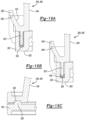
- FIGURE 17A - 17C generally depict a loudspeaker assembly 300' including an integrated loudspeaker grille 306 that includes a living hinge 600.
- the living hinge 600 enables the loudspeaker grille 306 to rotate within the opening 369.
- the living hinge 600 may rotate toward or away from the ramped surface 352.
- the living hinge 600 may be implemented or utilized on the grille enclosure 304 for any given loudspeaker size (e.g., 40mm, 80mm, etc.).
- FIGUREs 17A and 17C generally depict the loudspeaker assembly 300' with the living hinge 600 being in a fully opened state.
- FIGURE 17B generally depicts the loudspeaker assembly 300' with the living hinge 600 in a closed state.
- the living hinge 600 may be moved or rotated within the opening 369 and relative to the base enclosure 302. Such a rotation of the living hinge 600 may enable the plurality of louvers 361 to reside at any number of angles to prevent fluid intrusion without the need for a complex injection molding tool.
- the living hinge 600 may be formed of various plastic resins such as nylon, high density poly-ethylene (HDPE), low density poly-ethylene (LDPE), and polypropylene (PP).
- the living hinge 600 may correspond to a flexible protrusion that couples the loudspeaker grille 306 to the grille enclosure 304.
- the protrusion may be thinner than an overall thickness of the loudspeaker grille 306 to enable the grille 306 to rotate above the grille enclosure 304.
- FIGURE 18 generally depicts another example of the assembly 300, 400 in accordance with one embodiment. References to the various elements remain similar to those as set forth above unless stated differently in reference to FIGURE 18 .
- the integrated grille enclosure 304 includes the plurality of louvers 361 that define the openings 364. However, in this instance, the louvers 361 are not angled to overlap adjacent louvers. For example, the louvers 361 extend horizontally on an axis 700 that is perpendicular to the side 350c of the grille enclosure 304. In other words, the louvers 361 may be planar. It is recognized that the assembly 300, 400 may or may not include the living hinge 600.
- FIGURE 18 further illustrates that the grille enclosure 304 is generally planar.
- FIGURE 19 generally depicts another example of the assembly 300, 400 in accordance with one embodiment. References to the various elements remain similar to those as set forth above unless stated differently in reference to FIGURE 19 . As shown, the integrated grille enclosure 304 provides only the openings 364 to enable sound to transmit from the assembly 300, 400. It is recognized that the assembly 300, 400 may or may not include the living hinge 600. FIGURE 19 further illustrates that the grille enclosure 304 is generally planar.
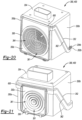
- FIGUREs 20 and 21 generally depict additional example of the assembly 300, 400 in accordance with one embodiment. References to the various elements remain similar to those as set forth above unless stated differently in reference to FIGUREs 20 and 21 .
- the integrated grille enclosure 306 includes the plurality of angled louvers 361 that define the openings 364. As shown, the integrated grille 306 may be non-planar. In one example, the integrated grille 306 may be shaped as a cone that tapers toward the loudspeaker 308 positioned within the base enclosure 302 and the grille enclosure 304. It is recognized that the assembly 300, 400 may or may not include the living hinge 600.
Landscapes
- Engineering & Computer Science (AREA)
- Physics & Mathematics (AREA)
- Acoustics & Sound (AREA)
- Signal Processing (AREA)
- Mechanical Engineering (AREA)
- Fittings On The Vehicle Exterior For Carrying Loads, And Devices For Holding Or Mounting Articles (AREA)
- Details Of Audible-Bandwidth Transducers (AREA)
Abstract
Description
- Aspects disclosed herein generally relate to an integrated loudspeaker assembly. For example, the integrated loudspeaker assembly may be used in various automotive applications. In particular, the disclosed integrated loudspeaker assembly may be used to generate alerts to pedestrians positioned exterior to a vehicle. These aspects and others will be discussed in more detail below.
- An Approaching Vehicle Alert System (AVAS) generally includes at least one loudspeaker that is positioned on the vehicle to provide alerts to pedestrians when the vehicle is moving in low speeds in an electric mode. Aspects of the AVAS may be mandated by regulation FMVSS141 for an Electric Vehicle (EV)/Plug-In Hybrid Electric Vehicle (PHEV)/Hybrid vehicle. The loudspeaker(s) is typically packaged outside of a cabin space of the vehicle in a front and/or rear locations of the vehicle. The loudspeakers may be subjected to harsh environment conditions such as extreme temperatures, humidity, water splash, dust, salt, snow, sand exposure, etc.
- In general, current loudspeakers and/or electronic controllers that are electrically coupled to the loudspeakers are packaged in enclosures to protect such loudspeakers and electronic controllers from the environment conditions. Current loudspeaker designs may require numerous assembly operations and numerous components to develop and tool. In addition, current loudspeaker designs may have more water sealing joints and thus provide more leak paths and hence less robust. Current loudspeaker designs may be more expensive since there are more components and overall complexity of the assembly process is increased.
- In at least one embodiment, a loudspeaker assembly for attachment to an exterior portion of a vehicle is provided. The assembly includes a loudspeaker, a base enclosure, and a grille enclosure. The loudspeaker transmits an audio output into an environment that is exterior to the vehicle. The base enclosure receives the loudspeaker and includes a first ramped surface formed on an exterior portion thereof. The grille enclosure includes an integrated loudspeaker grille to cover the loudspeaker. The grille enclosure further includes a second ramped surface positioned on an exterior portion thereof and being positioned directly adjacent to the first ramped surface of the base enclosure when the base enclosure is coupled to the grille enclosure. Each of the first ramped surface and the second ramped surface is non-perpendicular to the integrated loudspeaker grille.
- In at least one embodiment, a loudspeaker assembly for attachment to a vehicle is provided. The assembly includes a loudspeaker, a base enclosure, and a grille enclosure. The loudspeaker transmits an audio output from the vehicle. The base enclosure receives the loudspeaker and includes a first ramped surface formed on an exterior portion thereof. The grille enclosure includes an integrated loudspeaker grille to cover the loudspeaker. The grille enclosure further includes a second ramped surface on an exterior portion thereof and being positioned adjacent to the first ramped surface of the base enclosure when the base enclosure is coupled to the grille enclosure. Each of the first ramped surface and the second ramped surface extend along a non-perpendicular axis relative to the integrated loudspeaker grille.
- In at least one embodiment, a loudspeaker assembly for attachment to a vehicle is provided. The assembly includes a loudspeaker, a base enclosure, and a grille enclosure. The loudspeaker transmits an audio output from the vehicle. The base enclosure receives the loudspeaker and includes a first ramped surface formed thereon. The grille enclosure includes an integrated loudspeaker grille to cover the loudspeaker. The grille enclosure further includes a second ramped surface formed thereon and being positioned adjacent to the first ramped surface of the base enclosure when the base enclosure is coupled to the grille enclosure. Each of the first ramped surface and the second ramped surface extend along a non-perpendicular axis relative to the integrated loudspeaker grille.
- The embodiments of the present disclosure are pointed out with particularity in the appended claims. However, other features of the various embodiments will become more apparent and will be best understood by referring to the following detailed description in conjunction with the accompanying drawings in which:
-
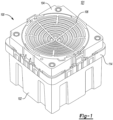
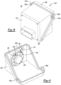
FIGURE 1 depicts one example of a loudspeaker assembly for an Approaching Vehicle Alert System (AVAS); -
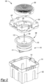
FIGURE 2 depicts an exploded view of the loudspeaker assembly ofFIGURE 1 ; -
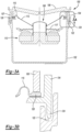
FIGURE 3A depicts a cross-sectional view of the loudspeaker assembly ofFIGURE 1 ; -
FIGURE 3B depicts a more detailed cross-sectional view of one aspect of the loudspeaker assembly ofFIGURE 3A ; -
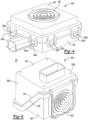
FIGURE 4 depicts another example of a loudspeaker assembly for the AVAS; -
FIGURE 5 depicts an exploded view of the loudspeaker assembly ofFIGURE 4 in accordance with an embodiment; -
FIGURE 6 depicts a loudspeaker assembly for the AVAS in accordance with an embodiment; -
FIGURE 7 depicts an exploded view of the loudspeaker assembly ofFIGURE 6 in accordance with an embodiment; -
FIGURE 8 depicts the manner in which the loudspeaker assembly may be positioned in the vehicle in accordance with one embodiment; -
FIGURE 9 depicts a rear view of the base enclosure in accordance with one embodiment; -
FIGURE 10A depicts a cross-sectional view of the loudspeaker assembly ofFIGURE 8 in accordance with an embodiment; -
FIGURE 10B depicts a more detailed cross-sectional view of one aspect of the loudspeaker assembly ofFIGURE 10A ; -
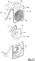
FIGURE 11 depicts another of a loudspeaker assembly for the AVAS in accordance with an embodiment; -
FIGURE 12 depicts a cross-sectional view of the loudspeaker assembly ofFIGURE 9 in accordance with an embodiment; -
FIGURE 13 depicts an exploded view of the loudspeaker assembly ofFIGURE 11 in accordance with an embodiment; -
FIGURE 14 depicts a side view of the assembly as illustrated in connection withFIGUREs 6 - 8 in accordance with one embodiment; -
FIGURE 15 depicts a side view of the assembly as illustrated in connection withFIGUREs 11 - 13 in accordance with one embodiment; -
FIGUREs 16A - 16C depict examples of locking features provided on a base enclosure and/or a grille enclosure in accordance with one embodiment; -
FIGURE 17A - 17C generally depict a loudspeaker assembly including an integrated loudspeaker grille that includes a living hinge in accordance with one embodiment; and -
FIGUREs 18 - 21 generally depict various loudspeaker assemblies with example of different loudspeaker grilles in accordance with one embodiment. - As required, detailed embodiments of the present invention are disclosed herein; however, it is to be understood that the disclosed embodiments are merely exemplary of the invention that may be embodied in various and alternative forms. The figures are not necessarily to scale; some features may be exaggerated or minimized to show details of particular components. Therefore, specific structural and functional details disclosed herein are not to be interpreted as limiting, but merely as a representative basis for teaching one skilled in the art to variously employ the present invention.
- With an increased focus by Original Equipment Manufacturers (OEMs) for EVs, it is desirable to provide a cost effective and robust design for loudspeakers used in connection with an AVAS. One method to improve reliability and overall quality for the loudspeaker may involve reducing an overall number of components used in constructing the loudspeaker. This approach also reduces the number of components to assemble which inherently reduces overall cost. For example, by combining an outer shell of the enclosure with a speaker grille, such an implementation may reduce components. In particular, the disclosed loudspeaker provides an enclosure including a speaker grille that are integrated with one another.
- Aspects disclosed herein generally provide the loudspeaker grille that is integrated with a portion of the enclosure and another portion that is coupled to the loudspeaker basket that provides a single assembly. The disclosed loudspeaker may be scalable to different sizes and may be used with predetermined materials to allow flexibility in vehicle level packaging. OEMs may also require electronic components (e.g., printed circuit board (PCB) assembly) related to AVAS in the same enclosure that houses the loudspeaker. The disclosed loudspeaker may be an AVAS based loudspeaker and that outputs an audio signal in response to an audio input provided by a controller. In addition, the disclosed loudspeaker may utilize adhesives and mechanical snap features to couple two portions of the enclosure together. The disclosed loudspeaker may be made watertight and may eliminate one or more gaskets which also reduces cost. Alternatively, the two halves may be welded via, for example, vibration welding to provide a tight joint that prevents fluid intrusion. A gasket between the two halves with snap features may also be implemented to provide a waterproof assembly.
-
FIGUREs 1 and2 depict one example of a loudspeaker assembly ("the assembly") 100 for an Approaching Vehicle Alert System (AVAS). Theassembly 100 may be positioned on an exterior portion of avehicle 101. Theassembly 100 include abase enclosure 102, abasket enclosure 104, and aloudspeaker grille 106. Thebasket enclosure 104 defines an opening for receiving theloudspeaker grille 106. Theassembly 100 includes aloudspeaker 108 and amagnetic motor assembly 110. Themagnetic motor assembly 110 generally includes a voice coil (not shown) and a magnetic core (not shown). As known, the voice coil and the magnetic core enable a cone (or diaphragm) 113 to generally move along afirst axis 109 to transmit an audio output signal. Theloudspeaker 108 may transmit the audio output signal anywhere from 160 to 5000 Hz. Thebasket enclosure 104 includes both abasket 105 that is integrated with an upper portion 107 (or upper half) of thebasket enclosure 104. Thebasket 105 and theupper portion 107 are integrated with one another. As shown, theloudspeaker 108 includes a lead assembly 111 (or lead wires), thecone 113, asurround 115, and a plurality of terminals (not shown). Thelead assembly 111 electrically couples theloudspeaker 108 to a power source (not shown) and an audio controller (not shown) via the terminals. - The
loudspeaker grille 106 covers theloudspeaker 108 and serves to protect the loudspeaker 108 (e.g., thelead assembly 111, thecone 113, thesurround 115, etc.) from direct contact from water or other objects. Thebase enclosure 102 defines anopening 112 for receiving theloudspeaker 108. Thebase enclosure 102 also forms a receivinglip 114 positioned on outer perimeter thereof. The receivinglip 114 receives an underside of thebasket enclosure 104. The receivinglip 114 and thebasket enclosure 104 form a water seal to prevent water or other fluid from intruding into theopening 112 and contacting the components that are associated with theloudspeaker 108. Theassembly 100 does not utilize screws to attach thebase enclosure 102 to thebasket enclosure 104. Rather, thebase enclosure 102 and thebasket enclosure 104 are coupled to one another via adhesive which also serves to seal the joint formed between thebase enclosure 102 and thebasket enclosure 104. Thebase enclosure 102 also provides a vent (not shown) that enables air to flow through while keeping fluids away from theloudspeaker 108. -
FIGURE 3A depicts a cross-sectional view of theloudspeaker assembly 100 ofFIGURE 1 .FIGURE 3B depicts a more detailed cross-sectional view of one aspect of theloudspeaker assembly 100 ofFIGURE 3A . Theloudspeaker 108 also includes aspider 117 positioned below thecone 113. Thesurround 115 includes anouter ring 120 that is integrated therewith. Theouter ring 120 receives one end of theloudspeaker grille 106. Adhesive is applied to an underside of thesurround 115 to attach theloudspeaker 108 to thebasket enclosure 104. Adhesive may also be applied between one end of theloudspeaker grille 106 and a top surface of theouter ring 120 to couple theloudspeaker grille 106 to theouter ring 120. Thebase enclosure 102 defines anouter channel 122 for receiving aprotrusion ring 124 of thebasket enclosure 104. Theprotrusion ring 124 of thebasket enclosure 104 is fixed within theouter channel 122 of thebase enclosure 102 to couple thebase enclosure 102 to thebasket enclosure 104.FIGURE 3A illustrates theloudspeaker grille 106 is not combined (or integrated) with thebasket enclosure 104 and such an implementation requires an additional operation (e.g., attaching theloudspeaker grille 106 to the basket enclosure 104) to the overall assembly process. -
FIGUREs 4 and5 depict another example of aloudspeaker assembly 200 for the AVAS. As shown, theassembly 200 also includes thebase enclosure 102, thebasket enclosure 104, theloudspeaker grille 106, and the loudspeaker 108 (seeFIGURE 5 ). Theassembly 200 generally includes components that are similar to those illustrated in connection with theassembly 100 ofFIGUREs 1-3 . However, for theassembly 200, theloudspeaker grille 106 is integrated with thebasket enclosure 104. Thebasket enclosure 104 includes a plurality of lockingribs 202a - 202d. Thebase enclosure 102 includes a plurality of lockingtabs 204a - 204d. The lockingtabs 204a - 204d are positioned over the lockingribs 202a - 202d to secure thebase enclosure 102 to thebasket enclosure 104. For example, the lockingtabs 204a - 204d slide over the lockingribs 202a - 202d and lock to theribs 202a - 202d once thetabs 204a - 204d reach an underside of theribs 202a - 202d. - The
basket 105 is packaged as a separate component from thebasket enclosure 104. In one example, thebasket 105 may be coupled to thebasket enclosure 104 via adhesive. As noted in connection with theassembly 100, theassembly 200 may also prevent water intrusion into thebase enclosure 102 and thebasket enclosure 104 to protect theloudspeaker 108. However, to fully prevent water for contacting various components of theloudspeaker 108, sealant may need to be added between thebasket enclosure 104 and thebasket 105 since such components are not integrated with one another and are coupled via adhesive which may cause leak paths. Because thebasket enclosure 104 and thebasket 105 are separate components, additional assembly operations may be required which adds expense and complexity. -
FIGUREs 6 and7 depict aloudspeaker assembly 300 in accordance with one embodiment. Theassembly 300 may be utilized for the AVAS or any other application in which a loudspeaker is required to be positioned in an external environment or may be exposed to harsh environmental conditions. Theassembly 300 includes abase enclosure 302 and agrille enclosure 304. Thegrille enclosure 304 includes aloudspeaker grille 306 that is integrated therewith. As shown, theloudspeaker grille 306 is integrated on a single side of thegrille enclosure 304. In addition, thebase enclosure 302 includes aloudspeaker basket 305 that is integrated therewith. - The
assembly 300 includes aloudspeaker 308, amagnetic motor assembly 310,lead wires 311a - 311b, a printed circuit board (PCB) 321, and a plurality ofterminals 323a - 323b (seeFIGURE 7 ). These components will be discussed in more detail below. As generally shown, thegrille enclosure 304 includes afirst side 350a and asecond side 350b each having an angled (or ramped)surface 352. Thegrille enclosure 304 includes athird side 350c in which theloudspeaker grille 306 is integrated thereon. Similarly, thebase enclosure 302 includes afirst side 360a and asecond side 360b each also having an angled (or ramped)surface 362. When thegrille enclosure 304 is mated to thebase enclosure 302, the rampedsurfaces FIGURE 6 . As shown the rampedsurface 352 on the first and thesecond sides loudspeaker grille 306 that is integrated with the grilledenclosure 304. - By utilizing the ramped
surface 352 that is formed on the first andsecond sides third side 350c including theloudspeaker grille 306 as integrated on thegrille enclosure 304. For example, the tool can insert a mold dispenser into anopening 369 formed by the rampedsurface 352 to then dispense the mold (or material) that forms thethird side 350c and theloudspeaker grille 306. The tool generally includes sliders and lifters that move (e.g., open or close) in various orientations or angles (or "action" as known in the art). Thus, the tool may be controlled with the assistance of action (e.g., additional movement both above and beyond the opening of core and cavity of the tool) to form the rampedsurface 352 on the first and thesecond sides integrated grille enclosure 304 on thethird side 350c. - The
loudspeaker grille 306 is configured to protect theloudspeaker 308 from receiving a direct splash of water or other fluid or debris while theassembly 300 is packaged on thevehicle 101. Theloudspeaker grille 306 enables air to pass from out of theassembly 300 and into the exterior environment. Theloudspeaker grille 306 includesangled louvers 361 defining a plurality ofopenings 364 to enable audio generated from theloudspeaker 308 to be transmitted to an external environment. - Adhesive may be applied to an entire seam (or interface) that is formed by the
base enclosure 302 and thegrille enclosure 304 when such components are mated with one another to seal the interface between the two. The manner in which thebase enclosure 302 and thegrille enclosure 304 may be coupled with one another will be discussed in more detail below. -
FIGURE 8 depicts the manner in which theloudspeaker assembly 300 may be positioned in thevehicle 101 in accordance with one embodiment. In general, theloudspeaker assembly 300 may be coupled to any exterior portion of thevehicle 101. Theloudspeaker 308 is generally orientated downward toward abottom 103 of thevehicle 101 and transmits audio toward the ground positioned below thevehicle 101. -
FIGURE 9 depicts a rear view of thebase enclosure 302 in accordance with one embodiment. As shown, theloudspeaker basket 305 defines anopening 309 for receiving an end of theloudspeaker 308. Theloudspeaker basket 305 includes a receivingportion 301 and defines an opening (not shown) therein. Avent disc 307 may be inserted into the receivingportion 301 and covers the opening within the receivingportion 301. Thevent disc 307 aids in regulating pressure due to temperature variations on theassembly 300 when sealed. Thevent disc 307 may be secured to the opening via adhesive (e.g., pressure sensitive adhesive) or by heat staking. Thebase enclosure 302 includes the plurality of lockingtabs 204a -204b for engagingcorresponding ribs 202a - 202b (seeFIGURE 8 for theribs 202a - 202b). -
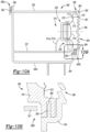
FIGURE 10A depicts a cross-sectional view of theloudspeaker assembly 300 ofFIGUREs 6 - 7 in accordance with an embodiment.FIGURE 10B depicts a more detailed cross-sectional view of theloudspeaker assembly 300 ofFIGURE 10A . Theloudspeaker grille 306 defines a plurality of grooves oropenings 364 to enable the audio output to be transmitted therefrom. As noted above, theloudspeaker grille 306 includes the plurality oflouvers 361 that are angled and that form the plurality ofopenings 364. Thelouvers 361 that form theopenings 364 are arranged per acoustic transparency to meet performance requirements. Additional embodiments will be discussed further below. - The
loudspeaker 308 includes themagnetic motor assembly 310, acone 313, acap 314, and asurround 315. Thecone 313 surrounds thecap 314. Thesurround 315 surrounds thecone 313 and thecap 314. Theloudspeaker 308 may be used as a 40 mm loudspeaker. It is recognized that the overall size of theloudspeaker 308 may vary based on the desired criteria of a particular implementation. As shown, theloudspeaker 308 is positioned about theloudspeaker basket 305. For example, theloudspeaker basket 305 includes abaffle 370 for receiving an end section of thesurround 315. ThePCB 321 is positioned below theloudspeaker 308 and is parallel to thesecond side 350b of thegrille enclosure 304. ThePCB 321 may be coupled to a side wall of thegrille enclosure 304 via adhesive, heat staking, or screws. Thelead wires PCB 321 viaterminals loudspeaker 308 to electrically couple theloudspeaker 308 to an audio controller. - The
base enclosure 302 and thegrille enclosure 304 are coupled to one another via a plurality ofengagement mechanisms 380a - 380b ("380") instead of the locking tabs and locking ribs as discussed above. Theengagement mechanisms 380a - 380b generally comprise a tongue and groove arrangement which enables thebase enclosure 302 to be coupled to thegrille enclosure 304. For example, each of theengagement mechanisms 380a - 380b may include atongue 382 and agroove 384. Thetongue 382 protrudes from a section of thegrille enclosure 304 and is received by thegroove 384 as formed in thebase enclosure 302. It is also recognized that thetongue 382 may be positioned on thebase enclosure 302 and that thegroove 384 may be formed on thegrille enclosure 304. Adhesive may be applied in various gaps that are present within or around thetongue 382 and thegroove 384 arrangement when thetongue 382 is inserted into thegroove 384 to aid in retaining or coupling thebase enclosure 302 to thegrille enclosure 304. In addition, anotherengagement mechanism 390 is provided in which aprotrusion 392 is provided on thebase enclosure 302 for being received by agroove 394 on thegrille enclosure 304. Similarly, adhesive may be applied to the interface formed by theprotrusion 392 and thegroove 394 to also aid in sealing and securing thebase enclosure 302 to thegrille enclosure 304. -
FIGUREs 11 - 13 depict anotherloudspeaker assembly 400 for the AVAS in accordance with an embodiment. Theassembly 400 is generally similar to the assembly as noted in connection withFIGUREs 6-8 , however, the size of theloudspeaker 308 is 80 mm and alead assembly 311 as shown inFIGURE 13 may be part of a voice coil of theloudspeaker 308. In general, the aspects noted in connection with theassembly 400 ofFIGURE 11 - 13 are similar to those noted in connection with theassembly 300 ofFIGUREs 6- 8 unless otherwise stated herein. -
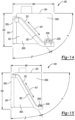
FIGURE 14 depicts a side view of theassembly 300 as illustrated in connection withFIGURE 8 . As noted above, theassembly 300 may include a loudspeaker size of, for example, 40 mm. As also noted above, when thegrille enclosure 304 is mated to thebase enclosure 302, the rampedsurfaces surface 352 on the first and thesecond sides grille enclosure 304 is generally inclined relative to theintegrated loudspeaker grille 306 on thegrille enclosure 304. Likewise, the rampedsurface 362 on the first and second sides of thebase enclosure 302 is generally inclined relative to theintegrated loudspeaker grille 306 on thegrille enclosure 304. In general, the rampedsurface 352 of thegrille enclosure 304 and the rampedsurface 362 of thebase enclosure 302 extend along anon-perpendicular axis 401 relative to theintegrated loudspeaker grille 306. - As shown, the
base enclosure 302 defines an overall length, L (e.g., see longitudinal axis 490). In addition, thebase enclosure 302 and thegrille enclosure 304 define an overall height, H (e.g., vertical axis 492). Thus, the rampedsurface 352 on the first and thesecond sides grille enclosure 304 is generally formed at an angle α in reference to theaxes surface 362 on the first andsecond sides base enclosure 302 is generally formed at an angle β in reference to theaxes grille enclosure 304 as shown inFIGURE 14 ) to the rampedsurface 352 where sealing occurs between thebase enclosure 302 and thegrille enclosure 304. The angle β includes the draft angle of a back side of the grille enclosure 304 (e.g., theside 350c) to the rampedsurface 362 - By providing the ramped
surface 352 of the first and thesecond sides surface 362 of the first andsecond sides assembly 300 may then provide theloudspeaker grille 306 that is integrated with thegrille enclosure 304. For example, such angles (e.g., α, β) enables the injection mold to provide theintegrated loudspeaker grille 306 with thegrille enclosure 304. As noted above, the injection tool generally includes sliders and lifters that move (e.g., open or close) in various orientations or angles (or "action" as known in the art). Thus, the tool may be controlled with the assistance of action (e.g., additional movement both above and beyond the opening of core and cavity of the tool) to form the rampedsurface 352 on the first and thesecond sides integrated grille enclosure 304 on thethird side 350c. -
FIGURE 15 depicts a side view of theassembly 400 as illustrated in connection withFIGURE 13 . As noted above, theassembly 400 may include a loudspeaker size of, for example, 80mm. As also noted above, when thegrille enclosure 304 is mated to thebase enclosure 302, the rampedsurfaces FIGURE 14 similarly apply to the rampedsurfaces FIGURE 15 . Similarly, as noted above withFIGURE 14 , The rampedsurface 352 of thegrille enclosure 304 and the rampedsurface 362 of thebase enclosure 302 extend along anon-perpendicular axis 401 relative to theintegrated loudspeaker grille 306. -
FIGURE 16A illustrates one example of locking features provided on thebase enclosure 302 and/or thegrille enclosure 304 to couplesuch enclosures assemblies base enclosure 302 forming areceiving section 502 that defines agroove 504. Atongue 520 protrudes from an end of thegrille enclosure 304 and is inserted into thegroove 504. Aflexible latch 506 having arecess 508 is formed on thebase enclosure 302. Thegrille enclosure 304 includes aledge 522 that is inserted into therecess 508 as thetongue 520 is fully positioned in thegroove 504. Any voids that are present in thegroove 504 after thetongue 520 is inserted therein may be filled with adhesive sealing. -
FIGURE 16B illustrates another example of locking features provided on thebase enclosure 302 and/or thegrille enclosure 304 in accordance with one embodiment. The embodiment illustrated in connection withFIGURE 16B is similar to that illustrated inFIGURE 16A . However, for the embodiment illustrated inFIGURE 16B , acompressible gasket 530 is positioned within thegroove 504 for receiving thetongue 520. Thecompressible gasket 530 may be used instead of the adhesive. -
FIGURE 16C illustrates another example of locking features provided on thebase enclosure 302 and/or thegrille enclosure 304 in accordance with one embodiment. Thebase enclosure 302 includes the tongue 520 (or a weld rib 520) that is formed on thebase enclosure 302. Thetongue 520 may be implemented as a weld rib. For example, theweld rib 520 may be melted via weld operation (or excited by movement) and flow onto a flat surface that is formed between thebase enclosure 302 and thegrille enclosure 304. Once cooled, thebase enclosure 302 and thegrille enclosure 304 are coupled to one another. In general, thebase enclosure 302 and thegrille enclosure 304 may be welded together (e.g., vibration welding) at via theweld rib 520. -
FIGURE 17A - 17C generally depict a loudspeaker assembly 300' including anintegrated loudspeaker grille 306 that includes aliving hinge 600. The livinghinge 600 enables theloudspeaker grille 306 to rotate within theopening 369. For example, the livinghinge 600 may rotate toward or away from the rampedsurface 352. It is recognized that theliving hinge 600 may be implemented or utilized on thegrille enclosure 304 for any given loudspeaker size (e.g., 40mm, 80mm, etc.).FIGUREs 17A and17C generally depict the loudspeaker assembly 300' with theliving hinge 600 being in a fully opened state.FIGURE 17B generally depicts the loudspeaker assembly 300' with theliving hinge 600 in a closed state. In general, the livinghinge 600 may be moved or rotated within theopening 369 and relative to thebase enclosure 302. Such a rotation of theliving hinge 600 may enable the plurality oflouvers 361 to reside at any number of angles to prevent fluid intrusion without the need for a complex injection molding tool. The livinghinge 600 may be formed of various plastic resins such as nylon, high density poly-ethylene (HDPE), low density poly-ethylene (LDPE), and polypropylene (PP). As shown in more detail in connection withFIGURE 17C , the livinghinge 600 may correspond to a flexible protrusion that couples theloudspeaker grille 306 to thegrille enclosure 304. The protrusion may be thinner than an overall thickness of theloudspeaker grille 306 to enable thegrille 306 to rotate above thegrille enclosure 304. -
FIGURE 18 generally depicts another example of theassembly FIGURE 18 . Theintegrated grille enclosure 304 includes the plurality oflouvers 361 that define theopenings 364. However, in this instance, thelouvers 361 are not angled to overlap adjacent louvers. For example, thelouvers 361 extend horizontally on an axis 700 that is perpendicular to theside 350c of thegrille enclosure 304. In other words, thelouvers 361 may be planar. It is recognized that theassembly living hinge 600.FIGURE 18 further illustrates that thegrille enclosure 304 is generally planar. -
FIGURE 19 generally depicts another example of theassembly FIGURE 19 . As shown, theintegrated grille enclosure 304 provides only theopenings 364 to enable sound to transmit from theassembly assembly living hinge 600.FIGURE 19 further illustrates that thegrille enclosure 304 is generally planar. -
FIGUREs 20 and 21 generally depict additional example of theassembly FIGUREs 20 and 21 . Theintegrated grille enclosure 306 includes the plurality ofangled louvers 361 that define theopenings 364. As shown, theintegrated grille 306 may be non-planar. In one example, theintegrated grille 306 may be shaped as a cone that tapers toward theloudspeaker 308 positioned within thebase enclosure 302 and thegrille enclosure 304. It is recognized that theassembly living hinge 600. - While exemplary embodiments are described above, it is not intended that these embodiments describe all possible forms of the invention. Rather, the words used in the specification are words of description rather than limitation, and it is understood that various changes may be made without departing from the spirit and scope of the invention. Additionally, the features of various implementing embodiments may be combined to form further embodiments of the invention.
Claims (15)
- A loudspeaker assembly for attachment to an exterior portion of a vehicle, the assembly comprising:a loudspeaker for transmitting an audio output into an environment that is exterior to the vehicle;a base enclosure to receive the loudspeaker and including a first ramped surface formed on an exterior portion thereof; anda grille enclosure including an integrated loudspeaker grille to cover the loudspeaker, the grille enclosure further including a second ramped surface positioned on an exterior portion thereof and being positioned directly adjacent to the first ramped surface of the base enclosure when the base enclosure is coupled to the grille enclosure,wherein each of the first ramped surface and the second ramped surface is non-perpendicular to the integrated loudspeaker grille.
- The loudspeaker assembly of claim 1, wherein the first ramped surface is formed at an angle that is greater than zero degrees and less than ninety degrees relative to the integrated loudspeaker grille.
- The loudspeaker assembly of claim 2, wherein the first ramped surface is formed at the angle of between twenty-eight degrees and sixty-three degrees relative to the integrated loudspeaker grille.
- The loudspeaker assembly of claim 1, wherein the second ramped surface is formed at an angle that is greater than zero degrees and less than ninety degrees relative to a first side of the grille enclosure.
- The loudspeaker assembly of claim 4, wherein the second ramped surface is formed at an angle that is between thirty degrees and sixty-five degrees relative to the first side of the grille enclosure.
- The loudspeaker assembly of claim 1, wherein first side of the grille enclosure is coupled to the exterior of the vehicle and the integrated loudspeaker grille is positioned opposite to the first side of the grille enclosure to enable the audio output to be transmitted directly into an ambient environment surrounding the vehicle.
- The loudspeaker assembly of claim 1, wherein the integrated loudspeaker grille includes a plurality of louvers defining a plurality of openings to enable the audio output to pass through the plurality of openings.
- The loudspeaker assembly of claim 7, wherein each of the plurality of louvers are angled and overlap one another to prevent fluid from contacting the loudspeaker.
- The loudspeaker assembly of claim 1, wherein the integrated loudspeaker grille includes a first end that is formed only on a single side of the grille enclosure.
- The loudspeaker assembly of claim 9, wherein the integrated loudspeaker grille includes a second end positioned opposite to the first end that is received by the base enclosure to couple the grille enclosure to the base enclosure.
- The loudspeaker assembly of claim 1, wherein the grille enclosure includes a living hinge positioned on the first end of the integrated loudspeaker grille to enable the integrated loudspeaker grille to rotate to and from the grille loudspeaker.
- The loudspeaker assembly of 1, wherein the base enclosure includes a loudspeaker basket integrated therewith to receive the loudspeaker.
- The loudspeaker assembly of claim 12, wherein the integrated loudspeaker grille covers the loudspeaker basket when the base enclosure is coupled with the grille enclosure.
- The loudspeaker assembly of claim 1, wherein the integrated loudspeaker grille includes a conical shaped portion and a plurality of openings formed thereon, and wherein the conical shaped portion and the plurality of openings extend inwardly toward the loudspeaker.
- The loudspeaker assembly of claim 14, wherein the integrated loudspeaker is generally planar and defines a plurality of openings thereon to enable the audio output to pass therethrough.
Applications Claiming Priority (1)
| Application Number | Priority Date | Filing Date | Title |
|---|---|---|---|
| US17/678,705 US11902728B2 (en) | 2022-02-23 | 2022-02-23 | Integrated loudspeaker assembly |
Publications (2)
| Publication Number | Publication Date |
|---|---|
| EP4236350A1 true EP4236350A1 (en) | 2023-08-30 |
| EP4236350B1 EP4236350B1 (en) | 2025-10-15 |
Family
ID=85321313
Family Applications (1)
| Application Number | Title | Priority Date | Filing Date |
|---|---|---|---|
| EP23157753.7A Active EP4236350B1 (en) | 2022-02-23 | 2023-02-21 | Integrated loudspeaker assembly |
Country Status (3)
| Country | Link |
|---|---|
| US (1) | US11902728B2 (en) |
| EP (1) | EP4236350B1 (en) |
| CN (1) | CN116647794A (en) |
Families Citing this family (2)
| Publication number | Priority date | Publication date | Assignee | Title |
|---|---|---|---|---|
| DE102023128414A1 (en) * | 2023-10-17 | 2025-04-17 | Brose Fahrzeugteile Se & Co. Kommanditgesellschaft, Bamberg | Loudspeaker unit for a vehicle and assembly method |
| DE102024001461B4 (en) * | 2024-05-04 | 2026-02-26 | Mercedes-Benz Group AG | Sound generation device for applications in an AVAS vehicle |
Citations (4)
| Publication number | Priority date | Publication date | Assignee | Title |
|---|---|---|---|---|
| JP2004074963A (en) * | 2002-08-20 | 2004-03-11 | Honda Access Corp | Speaker for vehicle and its mounting method |
| US20190222922A1 (en) * | 2018-01-18 | 2019-07-18 | Alpine Electronics, Inc. | In-vehicle speaker |
| WO2020207693A1 (en) * | 2019-04-09 | 2020-10-15 | Renault S.A.S | Unit comprising a casing and subwoofer duct with variable geometry |
| US20210197717A1 (en) * | 2018-06-04 | 2021-07-01 | Honda Motor Co., Ltd. | Sound-producing device for vehicle |
Family Cites Families (7)
| Publication number | Priority date | Publication date | Assignee | Title |
|---|---|---|---|---|
| JP6244540B2 (en) * | 2013-05-09 | 2017-12-13 | パナソニックIpマネジメント株式会社 | Speaker system and mobile device using the same |
| US10070237B2 (en) * | 2015-05-21 | 2018-09-04 | Analog Devices, Inc. | Optical and capacitive sensing of electroacoustic transducers |
| EP3199403B1 (en) * | 2016-01-28 | 2022-06-22 | Harman Becker Automotive Systems GmbH | System and method for external sound synthesis of a vehicle |
| US10531170B2 (en) * | 2016-09-01 | 2020-01-07 | Panasonic Intellectual Property Management Co., Ltd. | Loudspeaker device and movable-body apparatus equipped with same |
| GB201806194D0 (en) * | 2018-04-16 | 2018-05-30 | Native Design Ltd | Lighting and speaker device and annular LED assembly |
| US11627394B2 (en) * | 2019-12-31 | 2023-04-11 | Harman International Industries, Incorporated | Loudspeaker assembly for providing audio external to a vehicle |
| US20220363202A1 (en) * | 2021-05-14 | 2022-11-17 | Harman International Industries, Incorporated | Externally coupled loudspeaker assembly for a vehicle |
-
2022
- 2022-02-23 US US17/678,705 patent/US11902728B2/en active Active
-
2023
- 2023-02-21 CN CN202310140138.0A patent/CN116647794A/en active Pending
- 2023-02-21 EP EP23157753.7A patent/EP4236350B1/en active Active
Patent Citations (4)
| Publication number | Priority date | Publication date | Assignee | Title |
|---|---|---|---|---|
| JP2004074963A (en) * | 2002-08-20 | 2004-03-11 | Honda Access Corp | Speaker for vehicle and its mounting method |
| US20190222922A1 (en) * | 2018-01-18 | 2019-07-18 | Alpine Electronics, Inc. | In-vehicle speaker |
| US20210197717A1 (en) * | 2018-06-04 | 2021-07-01 | Honda Motor Co., Ltd. | Sound-producing device for vehicle |
| WO2020207693A1 (en) * | 2019-04-09 | 2020-10-15 | Renault S.A.S | Unit comprising a casing and subwoofer duct with variable geometry |
Also Published As
| Publication number | Publication date |
|---|---|
| US11902728B2 (en) | 2024-02-13 |
| US20230269505A1 (en) | 2023-08-24 |
| EP4236350B1 (en) | 2025-10-15 |
| CN116647794A (en) | 2023-08-25 |
Similar Documents
| Publication | Publication Date | Title |
|---|---|---|
| EP4236350A1 (en) | Integrated loudspeaker assembly | |
| JP7178993B2 (en) | Camera module and camera module manufacturing method | |
| US10499130B2 (en) | Speaker system such as a sound bar assembly having improved sound quality | |
| CN106941651B (en) | Loudspeaker module | |
| CN106921922A (en) | Loudspeaker module and electronic installation | |
| KR101853645B1 (en) | Lateral Sound Making Loudspeaker Module | |
| CN107850665A (en) | For the ultrasonic sensor equipment being arranged on the covering member of vehicle | |
| CN104106255A (en) | Waterproof box | |
| CN102045976B (en) | Electronic device | |
| US20090042098A1 (en) | Storage battery | |
| KR20160147737A (en) | Gas permeation member and production method therefor | |
| JP2014175366A (en) | Structure of ventilation part of waterproof case | |
| EP1416766B1 (en) | Hearing aid battery door seal | |
| US11404931B2 (en) | Driving device | |
| JP2020167905A (en) | Power supply device | |
| CN117014775A (en) | Sound producing device and electronic equipment | |
| CN206658294U (en) | Loudspeaker module | |
| JP3789851B2 (en) | Speaker box structure for vehicle doors | |
| US11750976B2 (en) | In-vehicle sound emitting device | |
| JP5037880B2 (en) | Terminal box for solar cell module | |
| CN206851019U (en) | Loudspeaker module and electronic installation | |
| CN209170614U (en) | Sounding device and earphone | |
| CN220383193U (en) | Microphone module | |
| CN102681299A (en) | Camera module | |
| JP5708855B1 (en) | Manufacturing method of electrical connector |
Legal Events
| Date | Code | Title | Description |
|---|---|---|---|
| PUAI | Public reference made under article 153(3) epc to a published international application that has entered the european phase |
Free format text: ORIGINAL CODE: 0009012 |
|
| STAA | Information on the status of an ep patent application or granted ep patent |
Free format text: STATUS: THE APPLICATION HAS BEEN PUBLISHED |
|
| AK | Designated contracting states |
Kind code of ref document: A1 Designated state(s): AL AT BE BG CH CY CZ DE DK EE ES FI FR GB GR HR HU IE IS IT LI LT LU LV MC ME MK MT NL NO PL PT RO RS SE SI SK SM TR |
|
| STAA | Information on the status of an ep patent application or granted ep patent |
Free format text: STATUS: REQUEST FOR EXAMINATION WAS MADE |
|
| 17P | Request for examination filed |
Effective date: 20240228 |
|
| RBV | Designated contracting states (corrected) |
Designated state(s): AL AT BE BG CH CY CZ DE DK EE ES FI FR GB GR HR HU IE IS IT LI LT LU LV MC ME MK MT NL NO PL PT RO RS SE SI SK SM TR |
|
| GRAP | Despatch of communication of intention to grant a patent |
Free format text: ORIGINAL CODE: EPIDOSNIGR1 |
|
| STAA | Information on the status of an ep patent application or granted ep patent |
Free format text: STATUS: GRANT OF PATENT IS INTENDED |
|
| RIC1 | Information provided on ipc code assigned before grant |
Ipc: H04R 1/02 20060101AFI20250621BHEP |
|
| INTG | Intention to grant announced |
Effective date: 20250702 |
|
| GRAS | Grant fee paid |
Free format text: ORIGINAL CODE: EPIDOSNIGR3 |
|
| GRAA | (expected) grant |
Free format text: ORIGINAL CODE: 0009210 |
|
| STAA | Information on the status of an ep patent application or granted ep patent |
Free format text: STATUS: THE PATENT HAS BEEN GRANTED |
|
| AK | Designated contracting states |
Kind code of ref document: B1 Designated state(s): AL AT BE BG CH CY CZ DE DK EE ES FI FR GB GR HR HU IE IS IT LI LT LU LV MC ME MK MT NL NO PL PT RO RS SE SI SK SM TR |
|
| P01 | Opt-out of the competence of the unified patent court (upc) registered |
Free format text: CASE NUMBER: UPC_APP_5966_4236350/2025 Effective date: 20250904 |
|
| REG | Reference to a national code |
Ref country code: GB Ref legal event code: FG4D Ref country code: CH Ref legal event code: F10 Free format text: ST27 STATUS EVENT CODE: U-0-0-F10-F00 (AS PROVIDED BY THE NATIONAL OFFICE) Effective date: 20251015 |
|
| REG | Reference to a national code |
Ref country code: IE Ref legal event code: FG4D |
|
| REG | Reference to a national code |
Ref country code: DE Ref legal event code: R096 Ref document number: 602023007407 Country of ref document: DE |
|
| REG | Reference to a national code |
Ref country code: NL Ref legal event code: MP Effective date: 20251015 |
|
| REG | Reference to a national code |
Ref country code: AT Ref legal event code: MK05 Ref document number: 1848143 Country of ref document: AT Kind code of ref document: T Effective date: 20251015 |
|
| PG25 | Lapsed in a contracting state [announced via postgrant information from national office to epo] |
Ref country code: NL Free format text: LAPSE BECAUSE OF FAILURE TO SUBMIT A TRANSLATION OF THE DESCRIPTION OR TO PAY THE FEE WITHIN THE PRESCRIBED TIME-LIMIT Effective date: 20251015 |
|
| PG25 | Lapsed in a contracting state [announced via postgrant information from national office to epo] |
Ref country code: ES Free format text: LAPSE BECAUSE OF FAILURE TO SUBMIT A TRANSLATION OF THE DESCRIPTION OR TO PAY THE FEE WITHIN THE PRESCRIBED TIME-LIMIT Effective date: 20251015 |
|
| REG | Reference to a national code |
Ref country code: LT Ref legal event code: MG9D |
|
| PG25 | Lapsed in a contracting state [announced via postgrant information from national office to epo] |
Ref country code: NO Free format text: LAPSE BECAUSE OF FAILURE TO SUBMIT A TRANSLATION OF THE DESCRIPTION OR TO PAY THE FEE WITHIN THE PRESCRIBED TIME-LIMIT Effective date: 20260115 |
|
| PGFP | Annual fee paid to national office [announced via postgrant information from national office to epo] |
Ref country code: DE Payment date: 20260121 Year of fee payment: 4 |
|
| PG25 | Lapsed in a contracting state [announced via postgrant information from national office to epo] |
Ref country code: HR Free format text: LAPSE BECAUSE OF FAILURE TO SUBMIT A TRANSLATION OF THE DESCRIPTION OR TO PAY THE FEE WITHIN THE PRESCRIBED TIME-LIMIT Effective date: 20251015 Ref country code: AT Free format text: LAPSE BECAUSE OF FAILURE TO SUBMIT A TRANSLATION OF THE DESCRIPTION OR TO PAY THE FEE WITHIN THE PRESCRIBED TIME-LIMIT Effective date: 20251015 Ref country code: FI Free format text: LAPSE BECAUSE OF FAILURE TO SUBMIT A TRANSLATION OF THE DESCRIPTION OR TO PAY THE FEE WITHIN THE PRESCRIBED TIME-LIMIT Effective date: 20251015 |
|
| PG25 | Lapsed in a contracting state [announced via postgrant information from national office to epo] |
Ref country code: RS Free format text: LAPSE BECAUSE OF FAILURE TO SUBMIT A TRANSLATION OF THE DESCRIPTION OR TO PAY THE FEE WITHIN THE PRESCRIBED TIME-LIMIT Effective date: 20260115 |
|
| PG25 | Lapsed in a contracting state [announced via postgrant information from national office to epo] |
Ref country code: IS Free format text: LAPSE BECAUSE OF FAILURE TO SUBMIT A TRANSLATION OF THE DESCRIPTION OR TO PAY THE FEE WITHIN THE PRESCRIBED TIME-LIMIT Effective date: 20260215 |
|
| PG25 | Lapsed in a contracting state [announced via postgrant information from national office to epo] |
Ref country code: PT Free format text: LAPSE BECAUSE OF FAILURE TO SUBMIT A TRANSLATION OF THE DESCRIPTION OR TO PAY THE FEE WITHIN THE PRESCRIBED TIME-LIMIT Effective date: 20260216 |
|
| PG25 | Lapsed in a contracting state [announced via postgrant information from national office to epo] |
Ref country code: PL Free format text: LAPSE BECAUSE OF FAILURE TO SUBMIT A TRANSLATION OF THE DESCRIPTION OR TO PAY THE FEE WITHIN THE PRESCRIBED TIME-LIMIT Effective date: 20251015 |
|
| PG25 | Lapsed in a contracting state [announced via postgrant information from national office to epo] |
Ref country code: LV Free format text: LAPSE BECAUSE OF FAILURE TO SUBMIT A TRANSLATION OF THE DESCRIPTION OR TO PAY THE FEE WITHIN THE PRESCRIBED TIME-LIMIT Effective date: 20251015 |