EP4236092A2 - Commande de liaison descendante pour transmission conjointe non cohérente - Google Patents
Commande de liaison descendante pour transmission conjointe non cohérente Download PDFInfo
- Publication number
- EP4236092A2 EP4236092A2 EP23163452.8A EP23163452A EP4236092A2 EP 4236092 A2 EP4236092 A2 EP 4236092A2 EP 23163452 A EP23163452 A EP 23163452A EP 4236092 A2 EP4236092 A2 EP 4236092A2
- Authority
- EP
- European Patent Office
- Prior art keywords
- dci
- downlink control
- control information
- data stream
- joint transmission
- Prior art date
- Legal status (The legal status is an assumption and is not a legal conclusion. Google has not performed a legal analysis and makes no representation as to the accuracy of the status listed.)
- Pending
Links
- 230000005540 biological transmission Effects 0.000 title claims abstract description 195
- 230000001427 coherent effect Effects 0.000 title abstract description 137
- 238000004891 communication Methods 0.000 claims abstract description 190
- 238000000034 method Methods 0.000 claims abstract description 69
- 238000013468 resource allocation Methods 0.000 claims description 17
- 230000001413 cellular effect Effects 0.000 abstract description 22
- 230000010267 cellular communication Effects 0.000 description 24
- 238000013461 design Methods 0.000 description 23
- 238000012545 processing Methods 0.000 description 16
- 230000006870 function Effects 0.000 description 14
- 238000010586 diagram Methods 0.000 description 13
- 238000013507 mapping Methods 0.000 description 12
- 230000011664 signaling Effects 0.000 description 10
- 238000013459 approach Methods 0.000 description 9
- 238000005516 engineering process Methods 0.000 description 8
- 230000009471 action Effects 0.000 description 6
- 230000007246 mechanism Effects 0.000 description 6
- 230000008569 process Effects 0.000 description 6
- 238000011161 development Methods 0.000 description 5
- 230000004044 response Effects 0.000 description 5
- 238000005259 measurement Methods 0.000 description 4
- 238000012986 modification Methods 0.000 description 4
- 230000004048 modification Effects 0.000 description 4
- 238000000638 solvent extraction Methods 0.000 description 4
- 230000004913 activation Effects 0.000 description 3
- 238000003491 array Methods 0.000 description 3
- 230000009286 beneficial effect Effects 0.000 description 3
- 230000009849 deactivation Effects 0.000 description 3
- 230000003213 activating effect Effects 0.000 description 2
- 230000002776 aggregation Effects 0.000 description 2
- 238000004220 aggregation Methods 0.000 description 2
- 230000008901 benefit Effects 0.000 description 2
- 238000004590 computer program Methods 0.000 description 2
- 230000006872 improvement Effects 0.000 description 2
- 238000007726 management method Methods 0.000 description 2
- 238000001228 spectrum Methods 0.000 description 2
- 230000007704 transition Effects 0.000 description 2
- 239000008186 active pharmaceutical agent Substances 0.000 description 1
- 239000004020 conductor Substances 0.000 description 1
- 238000013500 data storage Methods 0.000 description 1
- 230000001934 delay Effects 0.000 description 1
- 230000001419 dependent effect Effects 0.000 description 1
- 238000001514 detection method Methods 0.000 description 1
- 230000000694 effects Effects 0.000 description 1
- 235000019580 granularity Nutrition 0.000 description 1
- 238000009434 installation Methods 0.000 description 1
- 230000006855 networking Effects 0.000 description 1
- 230000003287 optical effect Effects 0.000 description 1
- 229920001690 polydopamine Polymers 0.000 description 1
- 239000002243 precursor Substances 0.000 description 1
- 239000004984 smart glass Substances 0.000 description 1
- 238000013519 translation Methods 0.000 description 1
Images


Classifications
-
- H—ELECTRICITY
- H04—ELECTRIC COMMUNICATION TECHNIQUE
- H04W—WIRELESS COMMUNICATION NETWORKS
- H04W88/00—Devices specially adapted for wireless communication networks, e.g. terminals, base stations or access point devices
- H04W88/02—Terminal devices
- H04W88/06—Terminal devices adapted for operation in multiple networks or having at least two operational modes, e.g. multi-mode terminals
-
- H—ELECTRICITY
- H04—ELECTRIC COMMUNICATION TECHNIQUE
- H04B—TRANSMISSION
- H04B7/00—Radio transmission systems, i.e. using radiation field
- H04B7/02—Diversity systems; Multi-antenna system, i.e. transmission or reception using multiple antennas
- H04B7/022—Site diversity; Macro-diversity
- H04B7/024—Co-operative use of antennas of several sites, e.g. in co-ordinated multipoint or co-operative multiple-input multiple-output [MIMO] systems
-
- H—ELECTRICITY
- H04—ELECTRIC COMMUNICATION TECHNIQUE
- H04W—WIRELESS COMMUNICATION NETWORKS
- H04W72/00—Local resource management
- H04W72/12—Wireless traffic scheduling
-
- H—ELECTRICITY
- H04—ELECTRIC COMMUNICATION TECHNIQUE
- H04B—TRANSMISSION
- H04B7/00—Radio transmission systems, i.e. using radiation field
- H04B7/02—Diversity systems; Multi-antenna system, i.e. transmission or reception using multiple antennas
- H04B7/04—Diversity systems; Multi-antenna system, i.e. transmission or reception using multiple antennas using two or more spaced independent antennas
- H04B7/0413—MIMO systems
-
- H—ELECTRICITY
- H04—ELECTRIC COMMUNICATION TECHNIQUE
- H04L—TRANSMISSION OF DIGITAL INFORMATION, e.g. TELEGRAPHIC COMMUNICATION
- H04L1/00—Arrangements for detecting or preventing errors in the information received
- H04L1/0001—Systems modifying transmission characteristics according to link quality, e.g. power backoff
- H04L1/0023—Systems modifying transmission characteristics according to link quality, e.g. power backoff characterised by the signalling
- H04L1/0028—Formatting
-
- H—ELECTRICITY
- H04—ELECTRIC COMMUNICATION TECHNIQUE
- H04L—TRANSMISSION OF DIGITAL INFORMATION, e.g. TELEGRAPHIC COMMUNICATION
- H04L5/00—Arrangements affording multiple use of the transmission path
- H04L5/003—Arrangements for allocating sub-channels of the transmission path
- H04L5/0032—Distributed allocation, i.e. involving a plurality of allocating devices, each making partial allocation
- H04L5/0035—Resource allocation in a cooperative multipoint environment
-
- H—ELECTRICITY
- H04—ELECTRIC COMMUNICATION TECHNIQUE
- H04L—TRANSMISSION OF DIGITAL INFORMATION, e.g. TELEGRAPHIC COMMUNICATION
- H04L5/00—Arrangements affording multiple use of the transmission path
- H04L5/003—Arrangements for allocating sub-channels of the transmission path
- H04L5/0053—Allocation of signaling, i.e. of overhead other than pilot signals
-
- H—ELECTRICITY
- H04—ELECTRIC COMMUNICATION TECHNIQUE
- H04L—TRANSMISSION OF DIGITAL INFORMATION, e.g. TELEGRAPHIC COMMUNICATION
- H04L5/00—Arrangements affording multiple use of the transmission path
- H04L5/0091—Signaling for the administration of the divided path
- H04L5/0094—Indication of how sub-channels of the path are allocated
-
- H—ELECTRICITY
- H04—ELECTRIC COMMUNICATION TECHNIQUE
- H04W—WIRELESS COMMUNICATION NETWORKS
- H04W72/00—Local resource management
- H04W72/12—Wireless traffic scheduling
- H04W72/1263—Mapping of traffic onto schedule, e.g. scheduled allocation or multiplexing of flows
- H04W72/1273—Mapping of traffic onto schedule, e.g. scheduled allocation or multiplexing of flows of downlink data flows
-
- H—ELECTRICITY
- H04—ELECTRIC COMMUNICATION TECHNIQUE
- H04W—WIRELESS COMMUNICATION NETWORKS
- H04W72/00—Local resource management
- H04W72/20—Control channels or signalling for resource management
- H04W72/23—Control channels or signalling for resource management in the downlink direction of a wireless link, i.e. towards a terminal
-
- H—ELECTRICITY
- H04—ELECTRIC COMMUNICATION TECHNIQUE
- H04W—WIRELESS COMMUNICATION NETWORKS
- H04W88/00—Devices specially adapted for wireless communication networks, e.g. terminals, base stations or access point devices
- H04W88/08—Access point devices
- H04W88/10—Access point devices adapted for operation in multiple networks, e.g. multi-mode access points
Definitions
- the present application relates to wireless devices, and more particularly to apparatus, systems, and methods for providing downlink control for non coherent joint transmission.
- Wireless communication systems are rapidly growing in usage.
- wireless devices such as smart phones and tablet computers have become increasingly sophisticated.
- many mobile devices now provide access to the internet, email, text messaging, and navigation using the global positioning system (GPS), and are capable of operating sophisticated applications that utilize these functionalities.
- GPS global positioning system
- Some examples of wireless communication standards include GSM, UMTS (associated with, for example, WCDMA or TD-SCDMA air interfaces), LTE, LTE Advanced (LTE-A), HSPA, 3GPP2 CDMA2000 (e.g., 1xRTT, 1xEV-DO, HRPD, eHRPD), IEEE 802.11 (WLAN or Wi-Fi), BLUETOOTH TM , etc.
- wireless communication devices The ever increasing number of features and functionality introduced in wireless communication devices also creates a continuous need for improvement in both wireless communications and in wireless communication devices.
- 5G fifth generation
- NR new radio
- Embodiments relate to apparatuses, systems, and methods to provide downlink control for non coherent joint transmission.
- the techniques described herein include various approaches to providing downlink control information for non coherent joint transmission data communications, including multiple possible downlink control information formats for each of non coherent joint transmission downlink data communications and non coherent joint transmission uplink data communications.
- the various formats for each of downlink and uplink non coherent joint transmission data communications may include a single downlink control information transmission, a multi-stage downlink control information transmission, and/or multiple downlink control information transmissions. Providing multiple such formats may allow for substantial flexibility when scheduling and configuring non coherent joint transmission communications.
- Techniques are also described herein for facilitating determining whether non coherent joint transmission is supported by a wireless device, and for determining when to activate or deactivate non coherent joint transmission, e.g., based on conditions being experienced by the wireless device, among various other techniques described herein.
- the techniques described herein may be implemented in and/or used with a number of different types of devices, including but not limited to cellular phones, tablet computers, wearable computing devices, portable media players, and any of various other computing devices.
- Memory Medium Any of various types of non-transitory memory devices or storage devices.
- the term "memory medium” is intended to include an installation medium, e.g., a CD-ROM, floppy disks, or tape device; a computer system memory or random access memory such as DRAM, DDR RAM, SRAM, EDO RAM, Rambus RAM, etc.; a non-volatile memory such as a Flash, magnetic media, e.g., a hard drive, or optical storage; registers, or other similar types of memory elements, etc.
- the memory medium may include other types of non-transitory memory as well or combinations thereof.
- the memory medium may be located in a first computer system in which the programs are executed, or may be located in a second different computer system which connects to the first computer system over a network, such as the Internet, In the latter instance, the second computer system may provide program instructions to the first computer for execution.
- the term "memory medium" may include two or more memory mediums which may reside in different locations, e.g., in different computer systems that are connected over a network.
- the memory medium may store program instructions (e.g., embodied as computer programs) that may be executed by one or more processors.
- Carrier Medium a memory medium as described above, as well as a physical transmission medium, such as a bus, network, and/or other physical transmission medium that conveys signals such as electrical, electromagnetic, or digital signals.
- a physical transmission medium such as a bus, network, and/or other physical transmission medium that conveys signals such as electrical, electromagnetic, or digital signals.
- Programmable Hardware Element - includes various hardware devices comprising multiple programmable function blocks connected via a programmable interconnect. Examples include FPGAs (Field Programmable Gate Arrays), PLDs (Programmable Logic Devices), FPOAs (Field Programmable Object Arrays), and CPLDs (Complex PLDs).
- the programmable function blocks may range from fine grained (combinatorial logic or lookup tables) to coarse grained (arithmetic logic units or processor cores).
- a programmable hardware element may also be referred to as "reconfigurable logic”.
- Computer System any of various types of computing or processing systems, including a personal computer system (PC), mainframe computer system, workstation, network appliance, Internet appliance, personal digital assistant (PDA), television system, grid computing system, or other device or combinations of devices.
- PC personal computer system
- mainframe computer system workstation
- network appliance Internet appliance
- PDA personal digital assistant
- television system grid computing system, or other device or combinations of devices.
- computer system can be broadly defined to encompass any device (or combination of devices) having at least one processor that executes instructions from a memory medium.
- UE User Equipment
- UE Device any of various types of computer systems or devices that are mobile or portable and that perform wireless communications.
- UE devices include mobile telephones or smart phones (e.g., iPhone TM , Android TM -based phones), portable gaming devices (e.g., Nintendo DS TM , PlayStation Portable TM , Gameboy Advance TM , iPhone TM ), laptops, wearable devices (e.g. smart watch, smart glasses), PDAs, portable Internet devices, music players, data storage devices, or other handheld devices, etc.
- the term “UE” or “UE device” can be broadly defined to encompass any electronic, computing, and/or telecommunications device (or combination of devices) which is easily transported by a user and capable of wireless communication.
- Wireless Device any of various types of computer systems or devices that perform wireless communications.
- a wireless device can be portable (or mobile) or may be stationary or fixed at a certain location.
- a UE is an example of a wireless device.
- a Communication Device any of various types of computer systems or devices that perform communications, where the communications can be wired or wireless.
- a communication device can be portable (or mobile) or may be stationary or fixed at a certain location.
- a wireless device is an example of a communication device.
- a UE is another example of a communication device.
- Base Station has the full breadth of its ordinary meaning, and at least includes a wireless communication station installed at a fixed location and used to communicate as part of a wireless telephone system or radio system.
- Processing Element refers to various elements or combinations of elements that are capable of performing a function in a device, such as a user equipment or a cellular network device.
- Processing elements may include, for example: processors and associated memory, portions or circuits of individual processor cores, entire processor cores, individual processors, processor arrays, circuits such as an ASIC (Application Specific Integrated Circuit), programmable hardware elements such as a field programmable gate array (FPGA), as well any of various combinations of the above.
- ASIC Application Specific Integrated Circuit
- FPGA field programmable gate array
- Channel - a medium used to convey information from a sender (transmitter) to a receiver.
- channel widths may be variable (e.g., depending on device capability, band conditions, etc.).
- LTE may support scalable channel bandwidths from 1.4 MHz to 20MHz.
- WLAN channels may be 22MHz wide while Bluetooth channels may be 1Mhz wide.
- Other protocols and standards may include different definitions of channels.
- some standards may define and use multiple types of channels, e.g., different channels for uplink or downlink and/or different channels for different uses such as data, control information, etc.
- band has the full breadth of its ordinary meaning, and at least includes a section of spectrum (e.g., radio frequency spectrum) in which channels are used or set aside for the same purpose.
- spectrum e.g., radio frequency spectrum
- Automatically - refers to an action or operation performed by a computer system (e.g., software executed by the computer system) or device (e.g., circuitry, programmable hardware elements, ASICs, etc.), without user input directly specifying or performing the action or operation.
- a computer system e.g., software executed by the computer system
- device e.g., circuitry, programmable hardware elements, ASICs, etc.
- An automatic procedure may be initiated by input provided by the user, but the subsequent actions that are performed "automatically” are not specified by the user, i.e., are not performed "manually", where the user specifies each action to perform.
- a user filling out an electronic form by selecting each field and providing input specifying information is filling out the form manually, even though the computer system must update the form in response to the user actions.
- the form may be automatically filled out by the computer system where the computer system (e.g., software executing on the computer system) analyzes the fields of the form and fills in the form without any user input specifying the answers to the fields.
- the user may invoke the automatic filling of the form, but is not involved in the actual filling of the form (e.g., the user is not manually specifying answers to fields but rather they are being automatically completed).
- the present specification provides various examples of operations being automatically performed in response to actions the user has taken.
- Approximately - refers to a value that is almost correct or exact. For example, approximately may refer to a value that is within 1 to 10 percent of the exact (or desired) value. It should be noted, however, that the actual threshold value (or tolerance) may be application dependent. For example, in some embodiments, “approximately” may mean within 0.1% of some specified or desired value, while in various other embodiments, the threshold may be, for example, 2%, 3%, 5%, and so forth, as desired or as required by the particular application.
- Concurrent - refers to parallel execution or performance, where tasks, processes, or programs are performed in an at least partially overlapping manner.
- concurrency may be implemented using "strong” or strict parallelism, where tasks are performed (at least partially) in parallel on respective computational elements, or using "weak parallelism", where the tasks are performed in an interleaved manner, e.g., by time multiplexing of execution threads.
- Configured to - Various components may be described as “configured to” perform a task or tasks. In such contexts, “configured to” is a broad recitation generally meaning “having structure that" performs the task or tasks during operation. As such, the component can be configured to perform the task even when the component is not currently performing that task (e.g., a set of electrical conductors may be configured to electrically connect a module to another module, even when the two modules are not connected). In some contexts, “configured to” may be a broad recitation of structure generally meaning “having circuitry that" performs the task or tasks during operation. As such, the component can be configured to perform the task even when the component is not currently on. In general, the circuitry that forms the structure corresponding to "configured to” may include hardware circuits.
- Figure 1 illustrates a simplified example wireless communication system, according to some embodiments. It is noted that the system of Figure 1 is merely one example of a possible system, and that features of this disclosure may be implemented in any of various systems, as desired.
- the example wireless communication system includes a base station 102A which communicates over a transmission medium with one or more user devices 106A, 106B, etc., through 106N.
- Each of the user devices may be referred to herein as a "user equipment” (UE).
- UE user equipment
- the user devices 106 are referred to as UEs or UE devices.
- the base station (BS) 102A may be a base transceiver station (BTS) or cell site (a "cellular base station"), and may include hardware that enables wireless communication with the UEs 106A through 106N.
- BTS base transceiver station
- cellular base station a base station
- the communication area (or coverage area) of the base station may be referred to as a "cell.”
- the base station 102A and the UEs 106 may be configured to communicate over the transmission medium using any of various radio access technologies (RATs), also referred to as wireless communication technologies, or telecommunication standards, such as GSM, UMTS (associated with, for example, WCDMA or TD-SCDMA air interfaces), LTE, LTE-Advanced (LTE-A), 5G new radio (5G NR), HSPA, 3GPP2 CDMA2000 (e.g., 1xRTT, 1xEV-DO, HRPD, eHRPD), etc.
- RATs radio access technologies
- GSM Global System for Mobile communications
- UMTS associated with, for example, WCDMA or TD-SCDMA air interfaces
- LTE LTE-Advanced
- 5G NR 5G new radio
- 3GPP2 CDMA2000 e.g., 1xRTT, 1xEV-DO, HRPD,
- the base station 102A may alternately be referred to as an 'eNodeB' or 'eNB'.
- the base station 102A is implemented in the context of 5G NR, it may alternately be referred to as a 'gNodeB' or 'gNB'.
- the base station 102A may also be equipped to communicate with a network 100 (e.g., a core network of a cellular service provider, a telecommunication network such as a public switched telephone network (PSTN), and/or the Internet, among various possibilities).
- a network 100 e.g., a core network of a cellular service provider, a telecommunication network such as a public switched telephone network (PSTN), and/or the Internet, among various possibilities.
- PSTN public switched telephone network
- the base station 102A may facilitate communication between the user devices and/or between the user devices and the network 100.
- the cellular base station 102A may provide UEs 106 with various telecommunication capabilities, such as voice, SMS and/or data services.
- Base station 102A and other similar base stations (such as base stations 102B...102N) operating according to the same or a different cellular communication standard may thus be provided as a network of cells, which may provide continuous or nearly continuous overlapping service to UEs 106A-N and similar devices over a geographic area via one or more cellular communication standards.
- each UE 106 may also be capable of receiving signals from (and possibly within communication range of) one or more other cells (which might be provided by base stations 102B-N and/or any other base stations), which may be referred to as "neighboring cells". Such cells may also be capable of facilitating communication between user devices and/or between user devices and the network 100. Such cells may include "macro" cells, “micro” cells, “pico” cells, and/or cells which provide any of various other granularities of service area size.
- base stations 102A-B illustrated in Figure 1 might be macro cells, while base station 102N might be a micro cell. Other configurations are also possible.
- base station 102A may be a next generation base station, e.g., a 5G New Radio (5G NR) base station, or "gNB".
- a gNB may be connected to a legacy evolved packet core (EPC) network and/or to a NR core (NRC) network.
- EPC legacy evolved packet core
- NRC NR core
- a gNB cell may include one or more transition and reception points (TRPs).
- TRPs transition and reception points
- a UE capable of operating according to 5G NR may be connected to one or more TRPs within one or more gNBs.
- the base station 102A and one or more other base stations 102 support joint transmission, such that UE 106 may be able to receive transmissions from multiple base stations (and/or multiple TRPs provided by the same base station).
- a UE 106 may be capable of communicating using multiple wireless communication standards.
- the UE 106 may be configured to communicate using a wireless networking (e.g., Wi-Fi) and/or peer-to-peer wireless communication protocol (e.g., Bluetooth, Wi-Fi peer-to-peer, etc.) in addition to at least one cellular communication protocol (e.g., GSM, UMTS (associated with, for example, WCDMA or TD-SCDMA air interfaces), LTE, LTE-A, 5G NR, HSPA, 3GPP2 CDMA2000 (e.g., 1xRTT, 1xEV-DO, HRPD, eHRPD), etc.).
- GSM Global System for Mobile communications
- UMTS associated with, for example, WCDMA or TD-SCDMA air interfaces
- LTE Long Term Evolution
- LTE-A Long Term Evolution
- 5G NR Fifth Generation
- HSPA High Speed Packet Access
- 3GPP2 CDMA2000 e.g.
- the UE 106 may also or alternatively be configured to communicate using one or more global navigational satellite systems (GNSS, e.g., GPS or GLONASS), one or more mobile television broadcasting standards (e.g., ATSC-M/H), and/or any other wireless communication protocol, if desired.
- GNSS global navigational satellite systems
- mobile television broadcasting standards e.g., ATSC-M/H
- any other wireless communication protocol if desired.
- Other combinations of wireless communication standards including more than two wireless communication standards are also possible.
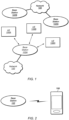
- FIG. 2 illustrates user equipment 106 (e.g., one of the devices 106A through 106N) in communication with a base station 102, according to some embodiments.
- the UE 106 may be a device with cellular communication capability such as a mobile phone, a hand-held device, a computer, a laptop, a tablet, a smart watch or other wearable device, or virtually any type of wireless device.
- the UE 106 may include a processor (processing element) that is configured to execute program instructions stored in memory.
- the UE 106 may perform any of the method embodiments described herein by executing such stored instructions.
- the UE 106 may include a programmable hardware element such as an FPGA (field-programmable gate array), an integrated circuit, and/or any of various other possible hardware components that are configured to perform (e.g., individually or in combination) any of the method embodiments described herein, or any portion of any of the method embodiments described herein.
- FPGA field-programmable gate array
- the UE 106 may include one or more antennas for communicating using one or more wireless communication protocols or technologies.
- the UE 106 may be configured to communicate using, for example, NR or LTE using at least some shared radio components.
- the UE 106 could be configured to communicate using CDMA2000 (1xRTT / 1xEV-DO / HRPD / eHRPD) or LTE using a single shared radio and/or GSM or LTE using the single shared radio.
- the shared radio may couple to a single antenna, or may couple to multiple antennas (e.g., for MIMO) for performing wireless communications.
- a radio may include any combination of a baseband processor, analog RF signal processing circuitry (e.g., including filters, mixers, oscillators, amplifiers, etc.), or digital processing circuitry (e.g., for digital modulation as well as other digital processing).
- the radio may implement one or more receive and transmit chains using the aforementioned hardware.
- the UE 106 may share one or more parts of a receive and/or transmit chain between multiple wireless communication technologies, such as those discussed above.
- the UE 106 may include separate transmit and/or receive chains (e.g., including separate antennas and other radio components) for each wireless communication protocol with which it is configured to communicate.
- the UE 106 may include one or more radios which are shared between multiple wireless communication protocols, and one or more radios which are used exclusively by a single wireless communication protocol.
- the UE 106 might include a shared radio for communicating using either of LTE or 5G NR (or either of LTE or 1xRTT, or either of LTE or GSM, among various possibilities), and separate radios for communicating using each of Wi-Fi and Bluetooth. Other configurations are also possible.
- FIG. 3 illustrates an example simplified block diagram of a communication device 106, according to some embodiments. It is noted that the block diagram of the communication device of Figure 3 is only one example of a possible communication device.
- communication device 106 may be a user equipment (UE) device, a mobile device or mobile station, a wireless device or wireless station, a desktop computer or computing device, a mobile computing device (e.g., a laptop, notebook, or portable computing device), a tablet, and/or a combination of devices, among other devices.
- the communication device 106 may include a set of components 300 configured to perform core functions.
- this set of components may be implemented as a system on chip (SOC), which may include portions for various purposes.
- SOC system on chip
- this set of components 300 may be implemented as separate components or groups of components for the various purposes.
- the set of components 300 may be coupled (e.g., communicatively; directly or indirectly) to various other circuits of the communication device 106.
- the communication device 106 may include various types of memory (e.g., including NAND flash 310), an input/output interface such as connector I/F 320 (e.g., for connecting to a computer system; dock; charging station; input devices, such as a microphone, camera, keyboard; output devices, such as speakers; etc.), the display 360, which may be integrated with or external to the communication device 106, and wireless communication circuitry 330 (e.g., for LTE, LTE-A, NR, UMTS, GSM, CDMA2000, Bluetooth, Wi-Fi, NFC, GPS, etc.).
- communication device 106 may include wired communication circuitry (not shown), such as a network interface card, e.g., for Ethernet.
- the wireless communication circuitry 330 may couple (e.g., communicatively; directly or indirectly) to one or more antennas, such as antenna(s) 335 as shown.
- the wireless communication circuitry 330 may include cellular communication circuitry and/or short to medium range wireless communication circuitry, and may include multiple receive chains and/or multiple transmit chains for receiving and/or transmitting multiple spatial streams, such as in a multiple-input multiple output (MIMO) configuration.
- MIMO multiple-input multiple output
- cellular communication circuitry 330 may include one or more receive chains (including and/or coupled to (e.g., communicatively; directly or indirectly) dedicated processors and/or radios) for multiple RATs (e.g., a first receive chain for LTE and a second receive chain for 5G NR).
- cellular communication circuitry 330 may include a single transmit chain that may be switched between radios dedicated to specific RATs. For example, a first radio may be dedicated to a first RAT, e.g., LTE, and may be in communication with a dedicated receive chain and a transmit chain shared with a second radio. The second radio may be dedicated to a second RAT, e.g., 5G NR, and may be in communication with a dedicated receive chain and the shared transmit chain.
- the communication device 106 may also include and/or be configured for use with one or more user interface elements.
- the user interface elements may include any of various elements, such as display 360 (which may be a touchscreen display), a keyboard (which may be a discrete keyboard or may be implemented as part of a touchscreen display), a mouse, a microphone and/or speakers, one or more cameras, one or more buttons, and/or any of various other elements capable of providing information to a user and/or receiving or interpreting user input.
- the communication device 106 may further include one or more smart cards 345 that include SIM (Subscriber Identity Module) functionality, such as one or more UICC(s) (Universal Integrated Circuit Card(s)) cards 345.
- SIM Subscriber Identity Module
- UICC Universal Integrated Circuit Card
- the SOC 300 may include processor(s) 302, which may execute program instructions for the communication device 106 and display circuitry 304, which may perform graphics processing and provide display signals to the display 360.
- the processor(s) 302 may also be coupled to memory management unit (MMU) 340, which may be configured to receive addresses from the processor(s) 302 and translate those addresses to locations in memory (e.g., memory 306, read only memory (ROM) 350, NAND flash memory 310) and/or to other circuits or devices, such as the display circuitry 304, wireless communication circuitry 330, connector I/F 320, and/or display 360.
- the MMU 340 may be configured to perform memory protection and page table translation or set up. In some embodiments, the MMU 340 may be included as a portion of the processor(s) 302.
- the communication device 106 may be configured to communicate using wireless and/or wired communication circuitry.
- the communication device 106 may include hardware and software components for implementing any of the various features and techniques described herein.
- the processor 302 of the communication device 106 may be configured to implement part or all of the features described herein, e.g., by executing program instructions stored on a memory medium (e.g., a non-transitory computer-readable memory medium).
- processor 302 may be configured as a programmable hardware element, such as an FPGA (Field Programmable Gate Array), or as an ASIC (Application Specific Integrated Circuit).
- the processor 302 of the communication device 106 in conjunction with one or more of the other components 300, 304, 306, 310, 320, 330, 340, 345, 350, 360 may be configured to implement part or all of the features described herein.
- processor 302 may include one or more processing elements.
- processor 302 may include one or more integrated circuits (ICs) that are configured to perform the functions of processor 302.
- each integrated circuit may include circuitry (e.g., first circuitry, second circuitry, etc.) configured to perform the functions of processor(s) 302.
- wireless communication circuitry 330 may include one or more processing elements. In other words, one or more processing elements may be included in wireless communication circuitry 330.
- wireless communication circuitry 330 may include one or more integrated circuits (ICs) that are configured to perform the functions of wireless communication circuitry 330.
- each integrated circuit may include circuitry (e.g., first circuitry, second circuitry, etc.) configured to perform the functions of wireless communication circuitry 330.
- FIG. 4 illustrates an example block diagram of a base station 102, according to some embodiments. It is noted that the base station of Figure 4 is merely one example of a possible base station. As shown, the base station 102 may include processor(s) 404 which may execute program instructions for the base station 102. The processor(s) 404 may also be coupled to memory management unit (MMU) 440, which may be configured to receive addresses from the processor(s) 404 and translate those addresses to locations in memory (e.g., memory 460 and read only memory (ROM) 450) or to other circuits or devices.
- MMU memory management unit
- the base station 102 may include at least one network port 470.
- the network port 470 may be configured to couple to a telephone network and provide a plurality of devices, such as UE devices 106, access to the telephone network as described above in Figures 1 and 2 .
- the network port 470 may also or alternatively be configured to couple to a cellular network, e.g., a core network of a cellular service provider.
- the core network may provide mobility related services and/or other services to a plurality of devices, such as UE devices 106.
- the network port 470 may couple to a telephone network via the core network, and/or the core network may provide a telephone network (e.g., among other UE devices serviced by the cellular service provider).
- base station 102 may be a next generation base station, e.g., a 5G New Radio (5G NR) base station, or "gNB".
- base station 102 may be connected to a legacy evolved packet core (EPC) network and/or to a NR core (NRC) network.
- EPC legacy evolved packet core
- NRC NR core
- base station 102 may be considered a 5G NR cell and may include one or more transition and reception points (TRPs).
- TRPs transition and reception points
- a UE capable of operating according to 5G NR may be connected to one or more TRPs within one or more gNBs.
- the base station 102 may include at least one antenna 434, and possibly multiple antennas.
- the at least one antenna 434 may be configured to operate as a wireless transceiver and may be further configured to communicate with UE devices 106 via radio 430.
- the antenna 434 communicates with the radio 430 via communication chain 432.
- Communication chain 432 may be a receive chain, a transmit chain or both.
- the radio 430 may be configured to communicate via various wireless communication standards, including, but not limited to, 5G NR, LTE, LTE-A, GSM, UMTS, CDMA2000, Wi-Fi, etc.
- the base station 102 may be configured to communicate wirelessly using multiple wireless communication standards.
- the base station 102 may include multiple radios, which may enable the base station 102 to communicate according to multiple wireless communication technologies.
- the base station 102 may include an LTE radio for performing communication according to LTE as well as a 5G NR radio for performing communication according to 5G NR.
- the base station 102 may be capable of operating as both an LTE base station and a 5G NR base station.
- the base station 102 may include a multi-mode radio which is capable of performing communications according to any of multiple wireless communication technologies (e.g., 5G NR and LTE, 5G NR and Wi-Fi, LTE and Wi-Fi, LTE and UMTS, LTE and CDMA2000, UMTS and GSM, etc.).
- a multi-mode radio which is capable of performing communications according to any of multiple wireless communication technologies (e.g., 5G NR and LTE, 5G NR and Wi-Fi, LTE and Wi-Fi, LTE and UMTS, LTE and CDMA2000, UMTS and GSM, etc.).
- the BS 102 may include hardware and software components for implementing or supporting implementation of features described herein.
- the processor 404 of the base station 102 may be configured to implement or support implementation of part or all of the methods described herein, e.g., by executing program instructions stored on a memory medium (e.g., a non-transitory computer-readable memory medium).
- the processor 404 may be configured as a programmable hardware element, such as an FPGA (Field Programmable Gate Array), or as an ASIC (Application Specific Integrated Circuit), or a combination thereof.
- processor 404 of the BS 102 in conjunction with one or more of the other components 430, 432, 434, 440, 450, 460, 470 may be configured to implement or support implementation of part or all of the features described herein.
- processor(s) 404 may include one or more processing elements.
- processor(s) 404 may include one or more integrated circuits (ICs) that are configured to perform the functions of processor(s) 404.
- each integrated circuit may include circuitry (e.g., first circuitry, second circuitry, etc.) configured to perform the functions of processor(s) 404.
- radio 430 may include one or more processing elements.
- radio 430 may include one or more integrated circuits (ICs) that are configured to perform the functions of radio 430.
- each integrated circuit may include circuitry (e.g., first circuitry, second circuitry, etc.) configured to perform the functions of radio 430.
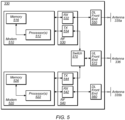
- Figure 5 illustrates an example simplified block diagram of cellular communication circuitry, according to some embodiments. It is noted that the block diagram of the cellular communication circuitry of Figure 5 is only one example of a possible cellular communication circuit; other circuits, such as circuits including or coupled to sufficient antennas for different RATs to perform uplink activities using separate antennas, or circuits including or coupled to fewer antennas, e.g., that may be shared among multiple RATs, are also possible. According to some embodiments, cellular communication circuitry 330 may be included in a communication device, such as communication device 106 described above.
- communication device 106 may be a user equipment (UE) device, a mobile device or mobile station, a wireless device or wireless station, a desktop computer or computing device, a mobile computing device (e.g., a laptop, notebook, or portable computing device), a tablet and/or a combination of devices, among other devices.
- UE user equipment
- mobile device or mobile station e.g., a mobile device or mobile station
- wireless device or wireless station e.g., a desktop computer or computing device
- a mobile computing device e.g., a laptop, notebook, or portable computing device
- tablet e.g., a tablet and/or a combination of devices, among other devices.
- the cellular communication circuitry 330 may couple (e.g., communicatively; directly or indirectly) to one or more antennas, such as antennas 335a-b and 336 as shown.
- cellular communication circuitry 330 may include dedicated receive chains (including and/or coupled to (e.g., communicatively; directly or indirectly) dedicated processors and/or radios) for multiple RATs (e.g., a first receive chain for LTE and a second receive chain for 5G NR).
- cellular communication circuitry 330 may include a first modem 510 and a second modem 520.
- the first modem 510 may be configured for communications according to a first RAT, e.g., such as LTE or LTE-A, and the second modem 520 may be configured for communications according to a second RAT, e.g., such as 5G NR.
- a first RAT e.g., such as LTE or LTE-A
- a second RAT e.g., such as 5G NR
- the first modem 510 may include one or more processors 512 and a memory 516 in communication with processors 512.
- Modem 510 may be in communication with a radio frequency (RF) front end 530.
- RF front end 530 may include circuitry for transmitting and receiving radio signals.
- RF front end 530 may include receive circuitry (RX) 532 and transmit circuitry (TX) 534.
- receive circuitry 532 may be in communication with downlink (DL) front end 550, which may include circuitry for receiving radio signals via antenna 335a.
- DL downlink
- the second modem 520 may include one or more processors 522 and a memory 526 in communication with processors 522.
- Modem 520 may be in communication with an RF front end 540.
- RF front end 540 may include circuitry for transmitting and receiving radio signals.
- RF front end 540 may include receive circuitry 542 and transmit circuitry 544.
- receive circuitry 542 may be in communication with DL front end 560, which may include circuitry for receiving radio signals via antenna 335b.
- a switch 570 may couple transmit circuitry 534 to uplink (UL) front end 572.
- switch 570 may couple transmit circuitry 544 to UL front end 572.
- UL front end 572 may include circuitry for transmitting radio signals via antenna 336.
- switch 570 may be switched to a first state that allows the first modem 510 to transmit signals according to the first RAT (e.g., via a transmit chain that includes transmit circuitry 534 and UL front end 572).
- switch 570 may be switched to a second state that allows the second modem 520 to transmit signals according to the second RAT (e.g., via a transmit chain that includes transmit circuitry 544 and UL front end 572).
- the first modem 510 and/or the second modem 520 may include hardware and software components for implementing any of the various features and techniques described herein.
- the processors 512, 522 may be configured to implement part or all of the features described herein, e.g., by executing program instructions stored on a memory medium (e.g., a non-transitory computer-readable memory medium).
- processors 512, 522 may be configured as a programmable hardware element, such as an FPGA (Field Programmable Gate Array), or as an ASIC (Application Specific Integrated Circuit).
- processors 512, 522, in conjunction with one or more of the other components 530, 532, 534, 540, 542, 544, 550, 570, 572, 335 and 336 may be configured to implement part or all of the features described herein.
- processors 512, 522 may include one or more processing elements.
- processors 512, 522 may include one or more integrated circuits (ICs) that are configured to perform the functions of processors 512, 522.
- each integrated circuit may include circuitry (e.g., first circuitry, second circuitry, etc.) configured to perform the functions of processors 512, 522.
- the cellular communication circuitry 330 may include only one transmit/receive chain.
- the cellular communication circuitry 330 may not include the modem 520, the RF front end 540, the DL front end 560, and/or the antenna 335b.
- the cellular communication circuitry 330 may not include the modem 510, the RF front end 530, the DL front end 550, and/or the antenna 335a.
- the cellular communication circuitry 330 may also not include the switch 570, and the RF front end 530 or the RF front end 540 may be in communication, e.g., directly, with the UL front end 572.
- New cellular communication techniques are continually under development, to increase coverage, to better serve the range of demands and use cases, and for a variety of other reasons.
- One technique that is currently under development may include non coherent joint transmission, in which multiple TRPs can schedule independent data streams to a wireless device without joint precoding.
- Figure 6 is a signal flow diagram illustrating an example of such a method, at least according to some embodiments. Aspects of the method of Figure 6 may be implemented by a wireless device such as a UE 106 illustrated in various of the Figures herein, a base station such as a BS 102 illustrated in various of the Figures herein, and/or more generally in conjunction with any of the computer circuitry, systems, devices, elements, or components shown in the above Figures, among others, as desired.
- a processor (and/or other hardware) of such a device may be configured to cause the device to perform any combination of the illustrated method elements and/or other method elements.
- some of the elements of the methods shown may be performed concurrently, in a different order than shown, may be substituted for by other method elements, or may be omitted. Additional elements may also be performed as desired. As shown, the method of Figure 6 may operate as follows.
- a wireless device may receive downlink control information for non coherent joint transmission.
- the downlink control information may be provided in any of a variety of possible formats.
- the wireless device may receive an indication of which of multiple possible formats is being used to provide the downlink control information. For example, such information may be broadcast by a base station to which the wireless device is attached in a system information broadcast, among various other possibilities.
- the downlink control information may be provided as a single downlink control information transmission that includes scheduling information for multiple downlink data streams of the non coherent joint transmission data communication.
- the downlink control information may include separate / independent scheduling information for each downlink data stream, or may include scheduling information that is common to the two downlink data streams and scheduling information that is specific to each of the two downlink data streams, e.g., to more efficiently communicate the scheduling information.
- the downlink control information may be provided as a multi-stage downlink control information transmission.
- the wireless device may receive a first portion of the multi-stage downlink control information transmission as well as a second portion of the multi-stage downlink control information transmission.
- the first portion may include scheduling information for a first downlink data stream of the non coherent joint transmission data communication
- the second portion may include scheduling information for a second downlink data stream of the non coherent joint transmission data communication.
- the first portion may include information indicating the existence of the second portion, and/or may include downlink control information configuration information for the second portion.
- the second portion may omit scheduling information for the second downlink data stream that is in common with the first downlink data stream, e.g., to more efficiently signal the downlink control information.
- the time and frequency resources on which the second portion are provided may be predetermined relative to time and frequency resources on which the first portion are provided, e.g., to simplify the decoding process for the wireless device.
- the downlink control information received by the wireless device may include first downlink control information for a first downlink data stream of the non coherent joint transmission data communication and separate second downlink control information for a second downlink data stream of the non coherent joint transmission data communication.
- the first downlink control information may include information indicating the existence of the second downlink control information
- the second downlink control information may include information indicating the existence of the first downlink control information.
- the first downlink control information may include configuration information for the second downlink control information
- the second downlink control information may include configuration information for the first downlink control information, at least according to some embodiments.
- time and frequency resources on which the second downlink control information is provided are predetermined relative to time and frequency resources on which the first downlink control information is provided, e.g., to simplify the decoding process for the wireless device.
- the second downlink control information may omit scheduling information for the second downlink data stream of the non coherent joint transmission data communication that is in common with the first downlink data stream of the non coherent joint transmission data communication.
- such a format may possibly enable support of non coherent joint transmission with TRPs that have a relatively low level of scheduling coordination.
- it may further be beneficial to provide a mechanism for semi-statically partitioning reference signal ports between TRPs associated with a non coherent joint transmission.
- reference signal ports may be semi-statically partitioned between the first TRP and the second TRP, and an indication of the partitioning of the reference signal ports between the first TRP and the second TRP may be provided to the wireless device.
- the downlink control information may be associated with a non coherent joint transmission uplink data communication, according to some embodiments. Similar to downlink control information associated with a non coherent joint transmission downlink data communication, there may be multiple possible formats that can be used for such downlink control information, at least according to some embodiments.
- the downlink control information may include a single downlink control information transmission scheduling a single non coherent joint transmission uplink data communication to multiple distributed reception points.
- the downlink control information may be a multi-stage downlink control information transmission, e.g., including a first portion that schedules a first uplink data stream to a first TRP and a second portion that schedules a second uplink data stream to a second TRP.
- the second portion may include incremental configuration information for the second uplink data stream relative to the first uplink data stream, such that configuration information for the second uplink data stream that is in common with the first uplink data stream may be omitted from the second portion.
- multiple downlink control information transmissions may be provided for the non coherent joint transmission uplink data communication, e.g., such that the wireless device may receive first downlink control information for a first uplink data stream of the non coherent joint transmission uplink data communication, and may separately receive second downlink control information for a second uplink data stream of the non coherent joint transmission uplink data communication transmission.
- the downlink control information for the non coherent joint transmission uplink data communication may include beam configuration information for the non coherent joint transmission uplink data communication.
- the downlink control information may include downlink reference signal index information indicating a downlink beam for a downlink reference signal, which may be considered an indication of a beam configuration to use for at least a portion of the non coherent joint transmission uplink data communication (e.g., for an uplink data stream that is transmitted to a TRP that provides the downlink reference signal via the downlink beam).
- the wireless device may use the downlink beam for the downlink reference signal as an uplink beam to transmit at least a portion of the non coherent joint transmission uplink data communication based at least in part on the downlink reference signal index information.
- similar configuration information may be received for each of multiple uplink beams to be used for multiple uplink data streams of the non coherent joint transmission uplink data communication.
- the downlink control information may potentially support a flexible MIMO layer to codeword mapping scheme.
- the downlink control information could include any or all of MIMO layer, MIMO codeword, and/or MIMO layer-to-codeword mapping information for the non coherent joint transmission data streams.
- the downlink control information may include transmission reception point (TRP) index information for the non coherent joint transmission downlink data communication.
- TRP index information may indicate which downlink data of the non coherent joint transmission downlink data communication is transmitted by which TRP.
- the wireless device may exchange signaling with the cellular network to determine whether non coherent joint transmission data communication is supported by both the wireless device and the cellular network, and/or to determine whether to activate non coherent joint transmission data communication, e.g., as a precursor to provision of the downlink control information for the non coherent joint transmission data communication.
- the wireless device may provide capability information, such as information indicating whether the wireless device supports simultaneous multiple beam transmission, whether the wireless device can transmit non coherent joint transmission beams associated with different antenna panels of the wireless device or the same antenna panel of the wireless device, whether the wireless device supports non coherent joint transmission uplink communication, and/or whether the wireless device supports non coherent joint transmission downlink communication.
- non coherent joint transmission is supported, and support is further provided for indicating whether to activate or deactivate non coherent joint transmission
- the wireless device provides a request to activate non coherent joint transmission, e.g., if the wireless device determines non coherent joint transmission would be beneficial.
- the cellular base station may provide an indication to activate non coherent joint transmission in response to the request, and the non coherent joint transmission communication may be performed based at least in part on the request to activate non coherent joint transmission and the indication to activate non coherent joint transmission.
- the wireless device may determine to request activation of non coherent joint transmission based on any of a variety of possible considerations, such as if the wireless device determines that a TRP strength difference between two TRPs is within a first threshold, if the wireless device determines that an uplink data buffer of the wireless device exceeds a buffer fullness threshold, and/or for any of various other possible reasons. Note additionally that it may be possible for a wireless device to support either, both, or neither of non coherent joint transmission uplink communication and downlink communication, and/or for each of non coherent joint transmission uplink communication and downlink communication to be activated/deactivated separately/independently or jointly, as desired.
- a given data stream may be (e.g., temporarily) disabled.
- a field of the downlink control information could be set to a reserved value to indicate that a downlink data stream associated with that portion of the downlink control information is disabled, as one possibility.
- Other techniques for signaling such possible disabling of a data stream of a non coherent joint transmission communication are also possible.
- the wireless device may be able to request deactivation of non coherent joint transmission, e.g., if the wireless device determines non coherent joint transmission would no longer be sufficiently beneficial.
- the wireless device may provide a request to deactivate non coherent joint transmission, and may receive an indication to deactivate non coherent joint transmission in response to the request to deactivate non coherent joint transmission.
- the request to deactivate non coherent joint transmission may be based on a TRP strength difference between two TRPs exceeding a predetermined threshold, an uplink data buffer of the wireless device being below a buffer fullness threshold, and/or for any of various other possible reasons.
- the wireless device may perform the non coherent joint transmission data communication, e.g., based at least in part on the downlink control information associated with the non coherent joint transmission data communication.
- performing the non coherent joint transmission data communication may include using scheduling information, configuration information, and/or other parameters/information provided in the downlink control information associated with the non coherent joint transmission data communication.
- the wireless device may receive a non coherent joint transmission downlink data communication, e.g., if the downlink control information is associated with a non coherent joint transmission downlink data communication.
- the wireless device may transmit a non coherent joint transmission uplink data communication, e.g., if the downlink control information is associated with a non coherent joint transmission uplink data communication.
- Figures 7-16 illustrate further aspects that might be used in conjunction with the method of Figure 6 if desired. It should be noted, however, that the exemplary details illustrated in and described with respect to Figures 7-16 are not intended to be limiting to the disclosure as a whole: numerous variations and alternatives to the details provided herein below are possible and should be considered within the scope of the disclosure.
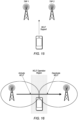
- Non coherent joint transmission is a topic under consideration at least for 3GPP cellular communication, for example in conjunction with 3GPP release 16.
- Figure 7 illustrates an example NCJT scenario, e.g., in which two TRPs schedule two data streams without joint precoding to a wireless device.
- Design of a non coherent joint transmission framework may include a variety of considerations, e.g., potentially including downlink control (e.g., physical downlink control channel and DCI) design, uplink feedback (e.g., physical uplink control channel and ACK/NAK) design, channel state information reference signal (CSI-RS) configuration design, and channel state information (CSI) feedback design, among various possibilities.
- downlink control e.g., physical downlink control channel and DCI
- uplink feedback e.g., physical uplink control channel and ACK/NAK
- CSI-RS channel state information reference signal
- CSI channel state information
- Each such design area may itself include a variety of considerations.
- downlink DCI design and uplink DCI design may need to be considered, as well as at least some overall NCJT operation considerations.
- the downlink DCI design there may be several possible approaches, including a single DCI design, a multi-stage DCI design, and/or a multiple DCI design.
- Figure 8 illustrates exemplary aspects of a possible single DCI approach.
- a UE may decode a single DCI transmission (e.g., from just one of the multiple TRPs) with scheduling information for both data streams.
- such an approach may include scheduling coordination support between the TRPs, e.g., such that the TRP providing the DCI is able to provide the scheduling information for both data streams in the DCI.
- Such a single DCI transmission may be formatted in a variety of ways.
- a single DCI that includes independent scheduling information for each data stream potentially including (but not limited to) frequency/time resource allocation, modulation and coding scheme (MCS), new data indicator (NDI), redundancy version (RV), hybrid automatic repeat request (HARQ) process number, antenna port, etc.
- MCS modulation and coding scheme
- NDI new data indicator
- RV redundancy version
- HARQ hybrid automatic repeat request
- a single DCI that includes some information that is in common for the two data streams and some information that is different for the two data streams could be used.
- the two data streams might have the same frequency/time resource allocation, but different MCS/NDI/RV, HARQ process number, antenna ports, etc. It may be possible for such a format to be more compact than a format in which scheduling information for each data stream is independently provided, though some scheduling flexibility may be lost to achieve such compactness.
- a NCJT DCI format used by a cellular base station could be signaled as part of system information (e.g., in one or more system information blocks (SIBs)).
- SIBs system information blocks
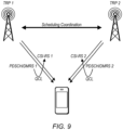
- the quasi-collocated (QCL) configuration may be independently configured for each TRP.
- QCL may allow a UE to assume that two RS share the similar channel properties (e.g., delay, doppler, etc.).
- each TRP may be configured with different DMRS ports (e.g., a group of DMRS ports), and QCL information regarding DMRS that belong to each TRP, and the corresponding CSI-RS, may be independently configured. This may allow a UE to determine which CSI-RS and PDSCH/DMRS transmissions are QCL, such as illustrated in Figure 9 .
- the DCI size for single TRP and two TRP scheduling may differ.
- the network can configure independent DCI for single TRP and two TRP scheduling.
- the single DCI can contain an explicit field that indicates which TRP is being scheduled.
- a single DCI format may include a mechanism to disable a TRP by setting a selected DCI field (e.g., resource allocation, MCS/RV/NDI, etc.) to a reserved value, thereby implicitly indicating that the TRP indicated as being scheduled is actually being disabled.
- a multi stage downlink DCI design for NCJT may also be possible.
- Figure 10 illustrates exemplary aspects of one such possible multi stage downlink DCI design.
- a first (e.g., main) DCI portion of the downlink control information may contain partial information for scheduling the two data streams, while a second (e.g., additional) DCI portion of the downlink control information may provide the remainder of the scheduling information, such that the full scheduling information may be available once both DCI portions have been decoded.
- the two DCIs may be provided by the same TRP or by different TRPs, which may in either case coordinate scheduling, as shown in Figure 10 .
- the first DCI may contain all of the scheduling information for the data stream for one of the TRPs, as well as an extra field to indicate the presence of the second TRP and the additional DCI that will provide additional scheduling information for scheduling the data stream for the other of the TRPs.
- the extra field can also provide further details on the DCI configuration for the second DCI, e.g., regarding the control resource set (CORESET), aggregation level, etc., to assist the UE with decoding the second DCI.
- CORESET control resource set
- aggregation level etc.
- the second DCI can have a smaller size, e.g., as common information with the first DCI may be omitted.
- common information For example, carrier ID information, bandwidth part (BWP) information, resource allocation, rate matching, virtual resource block (VRB) mapping, physical resource block (PRB) bundling, and/or any of various other parameters could be omitted from the second DCI portion, e.g., if they are the same for the second data stream as indicated in the first DCI portion for the first data stream.
- BWP bandwidth part
- VRB virtual resource block
- PRB physical resource block
- the first DCI portion and the second DCI portion may have resource (e.g., frequency and/or time) allocations that are implicitly linked, such that once the first DCI portion has been decoded, a LTE can readily determine the resource allocation for the second DCI portion.
- resource e.g., frequency and/or time
- a time division multiplexing approach in which the two DCI occupy the same frequency resource(s) in adjacent symbols could be used.
- a frequency division multiplexing approach in which the two DCI occupy adjacent frequency resources in the same symbol(s) could be used. Examples of such possible implicit resource allocation linkages are also illustrated in Figure 10 .
- a downlink DCI design for NCJT in which multiple DCI are provided is also possible, e.g., such that each DCI schedules the data stream from the corresponding TRP independently.
- Figures 11-12 illustrate exemplary aspects of one such possible multiple downlink DCI design. As shown, in such a design, a first DCI provided by a first TRP may schedule a first data stream to the UE, while a second DCI provided by a second TRP may schedule a second data stream to the UE.
- Such a configuration may be possible when the TRPs are not able to dynamically coordinate scheduling decisions, e.g., due to backhaul delays, and may thus be more practical in such scenarios, at least in some instances. Since the TRPs may not dynamically coordinate scheduling decisions, it may be the case that DMRS (e.g., up to 12 ports) and CSI-RS (e.g., up to 32 ports) configurations may be semi-statically configured/partitioned between the TRPs, possibly in a manner transparent to the UE. As another possibility, the semi-static partitioned DMRS ports can be signaled to the UE to reduce DCI size.
- DMRS e.g., up to 12 ports
- CSI-RS e.g., up to 32 ports
- the CORESET and search space can be independently configured for each DCI. This may facilitate coexistence between NCJT and non-NCJT operation, and reduce required UE complexity.
- the resource allocations for the two DCI can be implicitly linked, e.g., as shown in Figure 11 , in a time division multiplexing manner, in a frequency division multiplexing manner, or in any of various other possible ways of implicitly linking the resource allocations for the two DCI.
- each DCI may include an extra field (E) to indicate the existence of the other DCI.
- E extra field
- Providing such an indicator may help reduce the DCI decoding complexity e.g., by providing more details on DCI configuration, such as CORESET, aggregation level, etc., for the other DCI. Additionally or alternatively, such an indicator may help facilitate detection of DCI misdetection errors, e.g., by enabling the UE to determine when a DCI is provided but not decoded.
- the two DCI may have different sizes.
- the first DCI may schedule the first TRP, including the common scheduling information between the first TRP and the second TRP.
- the second DCI may schedule the second TRP with only the incremental information, e.g., such that common information may be omitted.
- any or all of carrier ID, BWP ID, resource allocation, rate matching, VRB mapping, PRB bundling, etc. may thus be included in the common information provided in the first DCI (e.g., if the same for both data streams) or may be included in both the first DCI and the second DCI (e.g., if different for the different data streams).
- uplink DCI For uplink DCI, similar format possibilities may be possible as for downlink DCI, at least according to some embodiments.
- a single DCI design may be used, in which a single DCI schedules an uplink data stream.
- Figure 13 illustrates exemplary aspects of one such possible single uplink DCI design.
- the multiple TRPs can serve as distributed reception points to enhance PUSCH decoding performance.
- a two stage uplink DCI may be used.
- the first stage DCI may schedule a first uplink data stream, potentially including the common scheduling information between the first uplink data stream and a second uplink data stream.
- the first stage DCI may also indicate the existence of a second stage DCI.
- the second stage DCI may schedule the incremental scheduling information for the second uplink data stream.
- Each DCI may schedule an uplink data stream corresponding to an individual TRP independently.
- a new transmission configuration indicator may be provided for uplink DCI communications.
- the TCI may indicate a CSI-RS/SSB index.
- the UE may in turn use the corresponding receive beam associated with the CSI-RS/SSB index to transmit the uplink data stream.
- multiple uplink data streams may be configured with different beam configurations, e.g., as uplink streams corresponding to different TRPs may be configured with different TCI or sounding reference symbol (SRS) index (SRI) values.
- SRS sounding reference symbol index
- Figure 14 illustrates exemplary aspects of such a configuration in which multiple uplink data streams having different beam configurations are transmitted by a UE.
- NCJT operation may increase throughput for UE devices, while also generally increasing UE complexity and power consumption.
- the UE may be expected to monitor multiple DCI and decode multiple physical downlink shared channels (PDSCH) simultaneously, and may need to activate multiple antenna panels in order to receive the multiple PDSCH. It may be the case that only a portion of UEs support NCJT operation, e.g., at least initially. Accordingly, it may be useful to provide a mechanism for indicating whether a UE supports NCJT.
- Figure 15 illustrates exemplary aspects of such an arrangement in which a UE can indicate that it supports NCJT operation.
- a UE that is capable of NCJT operation may not always wish to enable NCJT operation.
- Support for such signaling could be provided by use of temporary capability support signaling, e.g., to indicate whether a UE supports NCJT, and/or simultaneous operation of multiple antenna panels.
- Such signaling could be interpreted as a request (e.g., to activate NCJT if support is indicated by the UE, or to deactivate NCJT if support is not indicated by the UE) by the network.
- the network may also have discretion as to whether to activate or deactivate NCJT dynamically.
- activation/deactivation could be implemented via RRC signaling, MAC-CE signaling, and/or via DCI signaling.
- the network could also configure measurement reports to help with the decision whether to activate or deactivate NCJT.
- NCJT operation may be most effective when the difference between signal strength/quality for two TRPs is relatively small at a UE, and may be less effective when the difference between signal strength/quality for two TRPs is relatively large.
- a UE could be configured to report when the measurement difference for two TRPs is within a threshold (hysteresis) for a certain period of time (time to trigger), which could be taken under consideration as an indicator in favor of activating (or conversely against deactivating) NCJT by the network.
- a UE could be configured to report when the measurement difference for two TRPs exceeds a threshold (hysteresis) for a certain period of time (time to trigger), which could be taken under consideration as an indicator in favor of deactivating (or conversely against activating) NCJT by the network.
- Figure 16 illustrates how such a reporting mechanism might proceed in an exemplary possible UE mobility scenario, as an example.
- the network could also or alternatively configure UE reporting when the UE uplink buffer is lower than a certain threshold, and/or higher than a certain (e.g., same or different) threshold, for a certain period of time, as an indicator regarding whether to activate/deactivate NCJT operation for the UE.
- the network may also or alternatively consider the downlink buffer status (e.g., similarly whether its size is lower or higher than one or more thresholds for a certain period of time) for a UE as an indicator regarding whether to activate/deactivate NCJT operation for the UE.
- NCJT activation and deactivation of NCJT can be configured independently for each BWP for a UE, if desired.
- each TRP may have its own independent HARQ entity (with each HARQ entity containing multiple HARQ processes), at least according to some embodiments.
- the DCI may indicate a TRP index, which can be used to schedule cross TRP retransmissions, if desired.
- each PDSCH can be configured with its own TCI
- each PUSCH can be configured with its own SRI.
- UE measurement reporting may include whether multiple beams can be received or transmitted simultaneously.
- the report could be different for RX and TX, for example, if the two beams are supported for simultaneous reception but not transmission, or vice versa.
- reporting on whether beams belong to the same or different antenna panels could be supported/configured. Such reporting may be useful, at least in some instances, as beams in the same antenna panel may require less switching time compared to beams in different antenna panels. This may in turn affect scheduling, or possibly even whether the multiple beams are supported.
- One set of embodiments may include a method, comprising: by a wireless device: receiving downlink control information associated with a non coherent joint transmission downlink data communication; and receive the non coherent joint transmission downlink data communication based at least in part on the downlink control information.
- Another set of embodiments may include a method, comprising: by a cellular base station: providing downlink control information associated with a non coherent joint transmission downlink data communication to a wireless device; and transmitting a first portion of the non coherent joint transmission downlink data communication.
- the downlink control information comprises downlink a single downlink control information transmission comprising scheduling information for two data streams of the non coherent joint transmission data communication.
- the downlink control information comprises independent scheduling information for the two data streams.
- the downlink control information comprises scheduling information that is common to the two data streams and scheduling information that is specific to each of the two data streams.
- the downlink control information comprises multiple input multiple output (MIMO) layer and/or codeword mapping information for the two data streams.
- MIMO multiple input multiple output
- the downlink control information comprises multiple input multiple output (MIMO) layer to codeword mapping information for the two data streams.
- MIMO multiple input multiple output
- an indication of a downlink control information format for the downlink control information transmission is provided to the wireless device.
- the downlink control information comprises transmission reception point (TRP) index information for the non coherent joint transmission downlink data communication, wherein the TRP index information indicates which downlink data of the non coherent joint transmission downlink data communication is transmitted by which TRP.
- TRP transmission reception point
- At least one field of the downlink control information is set to a reserved value to indicate that a downlink data stream associated with that portion of the downlink control information is disabled.
- the downlink control information comprises a first portion of a multi-stage downlink control information transmission, wherein a second portion of the multi-stage downlink control information transmission is also provided to the wireless device.
- the first portion comprises scheduling information for a first data stream of the non coherent joint transmission data communication
- the second portion comprises scheduling information for a second data stream of the non coherent joint transmission data communication
- the first portion comprises information indicating the existence of the second portion.
- the first portion comprises downlink control information configuration information for the second portion.
- time and frequency resources on which the second portion are provided are predetermined relative to time and frequency resources on which the first portion are provided.
- the second portion omits scheduling information for the second data stream of the non coherent joint transmission data communication that is in common with the first data stream of the non coherent joint transmission data communication.
- the downlink control information comprises first downlink control information for a first data stream of the non coherent joint transmission data communication, wherein second downlink control information for a second data stream of the non coherent joint transmission data communication transmission is separately provided to the wireless device.
- downlink control information configuration for the first downlink control information and the second downlink control information are independently configured.
- time and frequency resources on which the second downlink control information is provided are predetermined relative to time and frequency resources on which the first downlink control information is provided.
- the first downlink control information comprises information indicating the existence of the second downlink control information
- the second downlink control information comprises information indicating the existence of the first downlink control information
- the first downlink control information comprises configuration information for the second downlink control information, wherein the second downlink control information comprises configuration information for the first downlink control information.
- the second downlink control information omits scheduling information for the second data stream of the non coherent joint transmission data communication that is in common with the first data stream of the non coherent joint transmission data communication.
- the first data stream is associated with a first transmission reception point (TRP), wherein the second data stream is associated with a second TRP, wherein reference signal ports are semi-statically partitioned between the first TRP and the second TRP, wherein an indication of the partitioning of the reference signal ports between the first TRP and the second TRP is provided to the wireless device.
- TRP transmission reception point
- the second data stream is associated with a second TRP
- reference signal ports are semi-statically partitioned between the first TRP and the second TRP, wherein an indication of the partitioning of the reference signal ports between the first TRP and the second TRP is provided to the wireless device.
- Yet another set of embodiments may include a method, comprising: by a wireless device: receiving downlink control information associated with a non coherent joint transmission uplink data communication; and transmitting the non coherent joint transmission uplink data communication based at least in part on the downlink control information.
- Still another set of embodiments may include a method, comprising: by a cellular base station: providing downlink control information associated with a non coherent joint transmission uplink data communication to a wireless device; and receiving at least a first portion of the non coherent joint transmission uplink data communication.
- the downlink control information comprises a single downlink control information transmission scheduling a single non coherent joint transmission data communication to multiple distributed reception points.
- the downlink control information comprises a first portion of a multi-stage downlink control information transmission, wherein the first portion schedules a first uplink data stream to a first transmission reception point (TRP), wherein a second portion of the multi-stage downlink control information transmission is also provided to the wireless device, wherein the second portion schedules a second uplink data stream to a second TRP, wherein the second portion comprises incremental configuration information for the second uplink data stream relative to the first uplink data stream, wherein configuration information for the second uplink data stream that is in common with the first uplink data stream is omitted from the second portion.
- TRP transmission reception point
- the downlink control information comprises first downlink control information for a first uplink data stream of the non coherent joint transmission uplink data communication, wherein second downlink control information for a second uplink data stream of the non coherent joint transmission uplink data communication transmission is separately provided to the wireless device.
- the downlink control information comprises beam configuration information for the non coherent joint transmission uplink data communication.
- the downlink control information comprises downlink reference signal index information indicating a downlink beam for a downlink reference signal, wherein the downlink beam for the downlink reference signal is also used as an uplink beam to transmit at least a portion of the non coherent joint transmission uplink data communication based at least in part on the downlink reference signal index information.
- the wireless device provides a request to activate non coherent joint transmission, wherein the cellular base station provides an indication to activate non coherent joint transmission, wherein the non coherent joint transmission communication is performed based at least in part on the request to activate non coherent joint transmission and the indication to activate non coherent joint transmission.
- the request to activate non coherent joint transmission is based at least in part on one or more of: the wireless device determining that a transmission reception point (TRP) strength difference between two TRPs is within a first threshold; or the wireless device determining that an uplink data buffer of the wireless device exceeds a buffer fullness threshold.
- TRP transmission reception point
- the wireless device provides a request to deactivate non coherent joint transmission, wherein, at the later time, the cellular base station provides an indication to deactivate non coherent joint transmission.
- the request to deactivate non coherent joint transmission is based at least in part on one or more of: the wireless device determining that a transmission reception point (TRP) strength difference between two TRPs exceeds a predetermined threshold; or the wireless device determining that an uplink data buffer of the wireless device is below a buffer fullness threshold.
- TRP transmission reception point
- the wireless device provides information indicating whether the wireless device supports simultaneous multiple beam transmission. According to some embodiments, the wireless device provides information indicating whether beams of the non coherent joint transmission are associated with different antenna panels of the wireless device or the same antenna panel of the wireless device.
- Another exemplary embodiment may include a device, comprising: an antenna; a radio coupled to the antenna; and a processing element operably coupled to the radio, wherein the device is configured to implement any or all parts of the preceding examples.
- Yet another exemplary embodiment may include a method, comprising: by a device: performing any or all parts of the preceding examples.
- a yet further exemplary embodiment may include a non-transitory computer accessible memory medium comprising program instructions which, when executed at a device, cause the device to implement any or all parts of any of the preceding examples.
- a still further exemplary embodiment may include a computer program comprising instructions for performing any or all parts of any of the preceding examples.
- Yet another exemplary embodiment may include an apparatus comprising means for performing any or all of the elements of any of the preceding examples.
- Still another exemplary embodiment may include an apparatus comprising a processing element configured to cause a wireless device to perform any or all of the elements of any of the preceding examples.
- personally identifiable information should follow privacy policies and practices that are generally recognized as meeting or exceeding industry or governmental requirements for maintaining the privacy of users.
- personally identifiable information data should be managed and handled so as to minimize risks of unintentional or unauthorized access or use, and the nature of authorized use should be clearly indicated to users.
- Embodiments of the present disclosure may be realized in any of various forms. For example some embodiments may be realized as a computer-implemented method, a computer-readable memory medium, or a computer system. Other embodiments may be realized using one or more custom-designed hardware devices such as ASICs. Still other embodiments may be realized using one or more programmable hardware elements such as FPGAs.
- a non-transitory computer-readable memory medium may be configured so that it stores program instructions and/or data, where the program instructions, if executed by a computer system, cause the computer system to perform a method, e.g., any of a method embodiments described herein, or, any combination of the method embodiments described herein, or, any subset of any of the method embodiments described herein, or, any combination of such subsets.
- a device e.g., a UE 106 or BS 102
- a device may be configured to include a processor (or a set of processors) and a memory medium, where the memory medium stores program instructions, where the processor is configured to read and execute the program instructions from the memory medium, where the program instructions are executable to implement any of the various method embodiments described herein (or, any combination of the method embodiments described herein, or, any subset of any of the method embodiments described herein, or, any combination of such subsets).
- the device may be realized in any of various forms.
Landscapes
- Engineering & Computer Science (AREA)
- Signal Processing (AREA)
- Computer Networks & Wireless Communication (AREA)
- Quality & Reliability (AREA)
- Mobile Radio Communication Systems (AREA)
Applications Claiming Priority (3)
| Application Number | Priority Date | Filing Date | Title |
|---|---|---|---|
| US201862738616P | 2018-09-28 | 2018-09-28 | |
| US16/579,108 US11516882B2 (en) | 2018-09-28 | 2019-09-23 | Downlink control for non coherent joint transmission |
| EP19200197.2A EP3641146A3 (fr) | 2018-09-28 | 2019-09-27 | Commande de liaison descendante pour transmission conjointe non cohérente |
Related Parent Applications (1)
| Application Number | Title | Priority Date | Filing Date |
|---|---|---|---|
| EP19200197.2A Division EP3641146A3 (fr) | 2018-09-28 | 2019-09-27 | Commande de liaison descendante pour transmission conjointe non cohérente |
Publications (2)
| Publication Number | Publication Date |
|---|---|
| EP4236092A2 true EP4236092A2 (fr) | 2023-08-30 |
| EP4236092A3 EP4236092A3 (fr) | 2023-10-04 |
Family
ID=68072279
Family Applications (2)
| Application Number | Title | Priority Date | Filing Date |
|---|---|---|---|
| EP23163452.8A Pending EP4236092A3 (fr) | 2018-09-28 | 2019-09-27 | Commande de liaison descendante pour transmission conjointe non cohérente |
| EP19200197.2A Pending EP3641146A3 (fr) | 2018-09-28 | 2019-09-27 | Commande de liaison descendante pour transmission conjointe non cohérente |
Family Applications After (1)
| Application Number | Title | Priority Date | Filing Date |
|---|---|---|---|
| EP19200197.2A Pending EP3641146A3 (fr) | 2018-09-28 | 2019-09-27 | Commande de liaison descendante pour transmission conjointe non cohérente |
Country Status (3)
| Country | Link |
|---|---|
| US (2) | US11516882B2 (fr) |
| EP (2) | EP4236092A3 (fr) |
| CN (2) | CN110972321B (fr) |
Families Citing this family (9)
| Publication number | Priority date | Publication date | Assignee | Title |
|---|---|---|---|---|
| EP3794876A1 (fr) * | 2018-05-14 | 2021-03-24 | Nokia Technologies Oy | Faciliter une réception discontinue pour équipement utilisateur à panneaux multiples |
| US11057957B2 (en) * | 2018-10-09 | 2021-07-06 | Cable Television Laboratories, Inc. | Systems and methods for joint wireless transmission and joint wireless reception |
| US20200304232A1 (en) * | 2019-03-21 | 2020-09-24 | Qualcomm Incorporated | Semi-dynamic rate matching |
| WO2020228950A1 (fr) * | 2019-05-15 | 2020-11-19 | Nokia Technologies Oy | Transmission et réception de pdcch à porteuse unique |
| CA3083316A1 (fr) * | 2019-06-11 | 2020-12-11 | Comcast Cable Communications, Llc | Transmission/reception des renseignements de controle et des communications sans fil |
| CN117793957A (zh) * | 2019-11-07 | 2024-03-29 | 苹果公司 | 用于快速单dci和多dci模式切换的系统和方法 |
| WO2021226884A1 (fr) * | 2020-05-13 | 2021-11-18 | Qualcomm Incorporated | Indication d'ue de transmission de liaison montante cohérente |
| WO2021227057A1 (fr) * | 2020-05-15 | 2021-11-18 | Qualcomm Incorporated | Configuration de transmission de liaison montante prenant en charge une transmission sur de multiples panneaux d'antenne |
| CN117279029A (zh) * | 2022-06-09 | 2023-12-22 | 中兴通讯股份有限公司 | 数据传输方法、终端、设备和存储介质 |
Family Cites Families (17)
| Publication number | Priority date | Publication date | Assignee | Title |
|---|---|---|---|---|
| JP5689029B2 (ja) * | 2011-06-09 | 2015-03-25 | 株式会社日立製作所 | 分散アンテナシステム、分散アンテナ割当方法、基地局装置 |
| US10932205B2 (en) * | 2013-08-02 | 2021-02-23 | Blackberry Limited | Uplink power sharing control |
| CN105265014B (zh) * | 2013-11-15 | 2019-10-22 | 华为技术有限公司 | 一种数据传输的方法及用户设备 |
| US10205425B2 (en) * | 2016-05-27 | 2019-02-12 | Qorvo Us, Inc. | Variable gain low noise amplifier |
| EP3445116B1 (fr) * | 2016-06-29 | 2022-05-11 | Huawei Technologies Co., Ltd. | Procédé, appareil et système de communication |
| EP3264619B1 (fr) * | 2016-07-01 | 2019-09-04 | Intel IP Corporation | Procédé et dispositif destinés à atténuer une interférence dans des émetteurs-récepteurs colocalisés |
| US10367566B2 (en) | 2016-08-12 | 2019-07-30 | Qualcomm Incorporated | Techniques for non-coherent joint transmissions in wireless communications |
| US10136331B2 (en) * | 2016-08-12 | 2018-11-20 | Alcatel Lucent | Enhancing coexistence on unlicensed frequency bands using adaptive clear-to-send-to-self messages |
| US10631329B2 (en) * | 2016-08-12 | 2020-04-21 | Qualcomm Incorporated | Non-coherent joint transmission techniques |
| US10405353B2 (en) * | 2016-09-23 | 2019-09-03 | Samsung Electronics Co., Ltd. | Method and apparatus for random access in wireless systems |
| WO2018063200A1 (fr) * | 2016-09-29 | 2018-04-05 | Intel IP Corporation | Dispositifs et procédés de terminal mobile dans des dispositifs de communication mobile |
| CN110169181B (zh) * | 2017-01-06 | 2021-01-15 | 华为技术有限公司 | 通信方法、装置和系统 |
| GB2562461B (en) * | 2017-03-24 | 2021-11-24 | Samsung Electronics Co Ltd | Resource management in coordinated multi-point wireless communication systems |
| EP3613161A4 (fr) * | 2017-04-21 | 2021-01-13 | Apple Inc. | Procédé et appareil de configuration de numérologie dans une transmission conjointe non cohérente |
| CN109151887B (zh) * | 2017-06-16 | 2023-10-24 | 华为技术有限公司 | 通信方法和通信装置 |
| CN108039903B (zh) * | 2017-09-11 | 2021-06-01 | 华为技术有限公司 | 一种通信方法及设备 |
| JP7171719B2 (ja) * | 2018-06-18 | 2022-11-15 | 株式会社Nttドコモ | 端末、無線通信方法、基地局及びシステム |
-
2019
- 2019-09-23 US US16/579,108 patent/US11516882B2/en active Active
- 2019-09-27 CN CN201910922142.6A patent/CN110972321B/zh active Active
- 2019-09-27 EP EP23163452.8A patent/EP4236092A3/fr active Pending
- 2019-09-27 EP EP19200197.2A patent/EP3641146A3/fr active Pending
- 2019-09-27 CN CN202310546223.7A patent/CN116506955A/zh active Pending
-
2022
- 2022-10-19 US US17/968,916 patent/US20230038005A1/en active Pending
Also Published As
| Publication number | Publication date |
|---|---|
| EP3641146A2 (fr) | 2020-04-22 |
| CN110972321B (zh) | 2023-06-06 |
| EP4236092A3 (fr) | 2023-10-04 |
| CN116506955A (zh) | 2023-07-28 |
| CN110972321A (zh) | 2020-04-07 |
| US11516882B2 (en) | 2022-11-29 |
| EP3641146A3 (fr) | 2020-07-29 |
| US20230038005A1 (en) | 2023-02-09 |
| US20200107400A1 (en) | 2020-04-02 |
Similar Documents
| Publication | Publication Date | Title |
|---|---|---|
| US11838975B2 (en) | TDM transmission for inter-RAT dual connectivity UE | |
| US11516882B2 (en) | Downlink control for non coherent joint transmission | |
| US11528776B2 (en) | Wireless device power saving for multi-TRP transmissions | |
| US11689273B2 (en) | Downlink signal reception with antenna panel switching | |
| US11855715B2 (en) | MIMO enhancement capability design | |
| US11616606B2 (en) | Cell edge reliability improvements | |
| US11638290B2 (en) | Downlink control for multi-TRP transmissions | |
| US20230291459A1 (en) | Downlink Signal Reception with Antenna Panel Switching | |
| WO2022151325A1 (fr) | Traitement de processus harq pour fonctionnement multi-dci multi-trp | |
| EP3799502A2 (fr) | Commande de liaison descendante pour transmissions multi-trp | |
| WO2022236685A1 (fr) | Mécanisme de traitement de tb sur un schéma à plusieurs intervalles de temps | |
| EP3681073A1 (fr) | Améliorations de la fiabilité de pourtour de cellules | |
| WO2022236535A1 (fr) | Multiplexage d'informations de commande de liaison montante (uci) pour un saut de demande de répétition automatique hybride (harq) de planification semi-persistante (sps) | |
| US20230361952A1 (en) | Ap-srs triggering offset enhancement for further enhanced mimo | |
| WO2022151340A1 (fr) | Amélioration de restriction de planification pour lte et dss de nr | |
| WO2023044720A1 (fr) | Procédés destinés à des améliorations de rapport de csi non basé sur le pmi pour une opération multi-trp |
Legal Events
| Date | Code | Title | Description |
|---|---|---|---|
| PUAI | Public reference made under article 153(3) epc to a published international application that has entered the european phase |
Free format text: ORIGINAL CODE: 0009012 |
|
| STAA | Information on the status of an ep patent application or granted ep patent |
Free format text: STATUS: REQUEST FOR EXAMINATION WAS MADE |
|
| 17P | Request for examination filed |
Effective date: 20230322 |
|
| AC | Divisional application: reference to earlier application |
Ref document number: 3641146 Country of ref document: EP Kind code of ref document: P |
|
| AK | Designated contracting states |
Kind code of ref document: A2 Designated state(s): AL AT BE BG CH CY CZ DE DK EE ES FI FR GB GR HR HU IE IS IT LI LT LU LV MC MK MT NL NO PL PT RO RS SE SI SK SM TR |
|
| PUAL | Search report despatched |
Free format text: ORIGINAL CODE: 0009013 |
|
| AK | Designated contracting states |
Kind code of ref document: A3 Designated state(s): AL AT BE BG CH CY CZ DE DK EE ES FI FR GB GR HR HU IE IS IT LI LT LU LV MC MK MT NL NO PL PT RO RS SE SI SK SM TR |
|
| RIC1 | Information provided on ipc code assigned before grant |
Ipc: H04L 5/00 20060101ALI20230829BHEP Ipc: H04B 7/024 20170101AFI20230829BHEP |