EP4236040A1 - Motor - Google Patents
Motor Download PDFInfo
- Publication number
- EP4236040A1 EP4236040A1 EP21882919.0A EP21882919A EP4236040A1 EP 4236040 A1 EP4236040 A1 EP 4236040A1 EP 21882919 A EP21882919 A EP 21882919A EP 4236040 A1 EP4236040 A1 EP 4236040A1
- Authority
- EP
- European Patent Office
- Prior art keywords
- conducting wire
- substrate
- recess
- recess part
- parts
- Prior art date
- Legal status (The legal status is an assumption and is not a legal conclusion. Google has not performed a legal analysis and makes no representation as to the accuracy of the status listed.)
- Pending
Links
Images







Classifications
-
- H—ELECTRICITY
- H02—GENERATION; CONVERSION OR DISTRIBUTION OF ELECTRIC POWER
- H02K—DYNAMO-ELECTRIC MACHINES
- H02K3/00—Details of windings
- H02K3/46—Fastening of windings on the stator or rotor structure
- H02K3/52—Fastening salient pole windings or connections thereto
- H02K3/521—Fastening salient pole windings or connections thereto applicable to stators only
- H02K3/522—Fastening salient pole windings or connections thereto applicable to stators only for generally annular cores with salient poles
-
- H—ELECTRICITY
- H02—GENERATION; CONVERSION OR DISTRIBUTION OF ELECTRIC POWER
- H02K—DYNAMO-ELECTRIC MACHINES
- H02K3/00—Details of windings
- H02K3/32—Windings characterised by the shape, form or construction of the insulation
- H02K3/34—Windings characterised by the shape, form or construction of the insulation between conductors or between conductor and core, e.g. slot insulation
-
- H—ELECTRICITY
- H02—GENERATION; CONVERSION OR DISTRIBUTION OF ELECTRIC POWER
- H02K—DYNAMO-ELECTRIC MACHINES
- H02K1/00—Details of the magnetic circuit
- H02K1/06—Details of the magnetic circuit characterised by the shape, form or construction
- H02K1/12—Stationary parts of the magnetic circuit
- H02K1/14—Stator cores with salient poles
-
- H—ELECTRICITY
- H02—GENERATION; CONVERSION OR DISTRIBUTION OF ELECTRIC POWER
- H02K—DYNAMO-ELECTRIC MACHINES
- H02K1/00—Details of the magnetic circuit
- H02K1/06—Details of the magnetic circuit characterised by the shape, form or construction
- H02K1/12—Stationary parts of the magnetic circuit
- H02K1/14—Stator cores with salient poles
- H02K1/146—Stator cores with salient poles consisting of a generally annular yoke with salient poles
- H02K1/148—Sectional cores
-
- H—ELECTRICITY
- H02—GENERATION; CONVERSION OR DISTRIBUTION OF ELECTRIC POWER
- H02K—DYNAMO-ELECTRIC MACHINES
- H02K2203/00—Specific aspects not provided for in the other groups of this subclass relating to the windings
- H02K2203/06—Machines characterised by the wiring leads, i.e. conducting wires for connecting the winding terminations
-
- H—ELECTRICITY
- H02—GENERATION; CONVERSION OR DISTRIBUTION OF ELECTRIC POWER
- H02K—DYNAMO-ELECTRIC MACHINES
- H02K2203/00—Specific aspects not provided for in the other groups of this subclass relating to the windings
- H02K2203/12—Machines characterised by the bobbins for supporting the windings
Definitions
- the present invention relates to a motor.
- a motor includes a plurality of stator cores, and both ends of a conducting wire wound around each stator core are physically and electrically connected to a connection member such as a bus bar or a substrate (for example, see PTL 1).
- connection member is a substrate
- a conducting wire hereinafter, also referred to as a "draw wire”
- the draw wire interferes with a wall part of an insulator, routing of the conducting wire is not easy, and the configuration needs to be improved in terms of the assemblability of the conducting wire with respect to the substrate.
- An object of the present invention is to provide a motor capable of improving the assemblability of a conducting wire with respect to a substrate.
- a motor includes a stator including a magnetic body, an insulator surrounding the magnetic body, and a coil formed of a conducting wire wound around the magnetic body via the insulator, and a substrate having an annular shape provided at the stator, wherein, of two drawing positions of the conducting wire drawn out from the coil, one drawing position is in an outer peripheral portion of the coil and the other drawing position is at an inside of the outer peripheral portion.
- the substrate includes a first recess part and a second recess part recessed at the inside in a radial direction from an outer peripheral end and adjacent to each other in a circumferential direction
- the insulator includes a wall part located at an outer peripheral side of the substrate in an assembled state with the substrate assembled to the stator
- the wall part includes a third recess part opposed to one of the two drawing positions of the conducting wire and a fourth recess part opposed to the other of the two drawing positions of the conducting wire
- the first recess part is opposed to the third recess part
- the second recess part is opposed to the fourth recess part.
- the assemblability of a conducting wire with respect to a substrate can be improved.
- a motor includes a coil formed of a conducting wire; and an insulator including an outer surface surrounded by the coil, wherein the outer surface of the insulator includes a plurality of recess parts and a flat surface, and parts of the conducting wire opposed to the flat surface are spaced from parts of the conducting wire fitted into the plurality of recess parts.
- contact between coils wound around stator cores adjacent to each other in a circumferential direction can be suppressed.
- a motor includes: a stator including a magnetic body and a conducting wire wound around the magnetic body; and a substrate having an annular shape provided at the stator, wherein the substrate includes a first recess part and a second recess part recessed at an inside in a radial direction from an outer peripheral end and adjacent to each other in a circumferential direction, and, of two end parts of the conducting wire, a first end part is located at an inside of the first recess part and a second end part is located at an inside of the second recess part, and the first end part and the second end part are disposed in a direction opposing each other in the circumferential direction.
- a load applied to a conducting wire arranged between a stator and a substrate can be reduced.
- a motor includes: a stator including a magnetic body and a conducting wire wound around the magnetic body; and a substrate having an annular shape provided at the stator, wherein the substrate includes one or more recess parts recessed at an inside in a radial direction from an outer peripheral end, and a land having conductivity and connected to the conducting wire, an end part of the conducting wire being disposed at an inside of the recess part, the land includes a first land disposed at a front surface side of the substrate along the recess part, a second land disposed at a rear surface side of the substrate along the recess part, and a third land disposed at an inner peripheral surface of the recess part, and the first land, the second land, and the third land communicate with one another.
- the assemblability of a conducting wire with respect to a substrate can be improved.
- FIG. 1 is an external perspective view of a stator according to an embodiment.
- FIG. 2 is a partially exploded perspective view of a stator according to the embodiment.
- FIG. 3 is a vertical sectional view of the stator according to the embodiment.
- FIG. 4 is an external perspective view of a segment core constituting the stator.
- FIG. 5 is an enlarged plan view of a connection portion between the segment core and a substrate.
- FIG. 6 is a partially exploded perspective view of the segment core.
- FIG. 7 is a schematic cross-sectional view of an insulator and a coil constituting the segment core.
- FIG. 8 is a schematic cross-sectional view of adjacent segment cores.
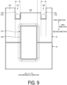
- FIG. 9 is a vertical sectional view of the insulator.
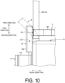
- FIG. 10 is a schematic view illustrating a change in a position of a conducting wire when the substrate is assembled to the segment core.
- FIG. 11A is an enlarged side view of the connection portion between the segment core and the substrate.
- FIG. 11B is a schematic view illustrating an example of a soldering state of the conducting wire to a substrate recess part.
- the axial direction in the illustration is a rotational axis direction of the motor of the present embodiment.
- one direction is a first direction and the other direction is a second direction.
- the radial direction illustrated in the drawing is the radial direction orthogonal to the rotational axis direction of the motor of the present embodiment.
- a direction away from a rotational axis X illustrated is the outside in the radial direction, and the direction toward the rotational axis X is the inside in the radial direction.
- the circumferential direction illustrated in the drawing is a direction coinciding with the rotational direction of the motor of the present embodiment.
- a stator 1 according to the present embodiment is applied to, for example, an inner rotor type brushless motor or the like.
- a motor of the present embodiment includes an inner rotor as a rotor, a shaft fixed at the inner rotor, the stator 1 having a coil and a magnetic body wound around with the coil, and a substrate 2 having an annular shape provided at the stator 1.
- the motor employing the stator 1 is not limited to a brushless motor.
- the stator 1 illustrated in FIG. 1 is disposed to surround the inner rotor (not illustrated).
- the stator 1 includes a plurality of segment cores 10 as so-called segment cores.
- the stator 1 is formed by disposing the plurality of segment cores 10 along the circumferential direction in an annular shape and joining and integrating the adjacent segment cores 10.
- the substrate 2 formed in an annular shape is disposed at the side of the first direction in the axial direction.
- the plurality of segment cores 10 are integrated by insert molding while being disposed along the circumferential direction in an annular shape, for example.
- the segment core 10 includes a stator core 11, an insulator 12, and a coil 13 surrounding the stator core 11 via the insulator 12.
- the stator core 11 is a magnetic body having a layered structure obtained by layering a plurality of electromagnetic steel plates and the like, for example.
- a plurality of the stator cores 11 is disposed along the circumferential direction in an annular shape.
- the stator core 11 includes a tooth part 11a and a yoke part 11b.
- the tooth part 11a extends to the inside in the radial direction from an inner peripheral side of the yoke part 11b.
- the yoke part 11b is connected to the adjacent yoke part 11b in the circumferential direction, with the plurality of segment cores 10 disposed along the circumferential direction in an annular shape.
- the insulator 12 is formed of, for example, an insulating body and is interposed between the stator core 11 and the coil 13 to electrically insulate the coil 13 and the stator core 11.
- the insulator 12 includes an accommodation part 121 accommodating the stator core 11 inside, and a wall part 122 formed at an end part at the outside in the radial direction of the accommodation part 121.
- the insulator 12 is formed to be divided into two parts, and can accommodate the stator core 11 inside in the divided state.
- the wall part 122 is located at the outer peripheral side of the substrate 2 in an assembled state with the substrate 2 assembled to the stator 1. When viewed from the radial direction, the wall part 122 is formed in a substantially rectangular shape, and is formed to protrude from the yoke part 11b in the axial direction.
- the wall part 122 includes two recess parts in the radial direction opposed to the drawing positions of two conducting wires 14 drawn out from the coil 13. Specifically, as illustrated in FIG. 9 , the wall part 122 includes an insulator-side first recess part 126 and an insulator-side second recess part 127.
- the insulator-side first recess part 126 (third recess part) is formed corresponding to one of the drawing positions of the conducting wire 14, and the one conducting wire 14 is disposed at the inside along the direction intersecting the extending direction of the one conducting wire 14.
- the insulator-side second recess part 127 (fourth recess part) is formed corresponding to the other of the drawing positions of the conducting wire 14, and the other conducting wire 14 is disposed at the inside along the direction intersecting the extending direction of the other conducting wire 14. As illustrated in FIGS. 5 and 11A , the insulator-side first recess part 126 and the insulator-side second recess part 127 are formed at the segment core 10 at positions opposed to the drawing positions of the conducting wire 14 drawn from the coil 13.
- the insulator-side first recess part 126 is formed at the segment core 10 at a position opposed to a first end part 141 of the conducting wire 14 drawn out from the coil 13.
- the insulator-side second recess part 127 is formed at the segment core 10 at a position opposed to a second end part 142 of the conducting wire 14 drawn out from the coil 13.
- An insulator-side protruding part 128 is formed between the insulator-side first recess part 126 and the insulator-side second recess part 127 in the circumferential direction.
- the insulator-side protruding part 128 extends outward without protruding from an end part of the wall part 122 in the first direction in the axial direction.
- the insulator-side protruding part 128 is opposed to a substrate protruding part 23 in the axial direction in the assembled state with the substrate 2 assembled to the stator 1.
- the insulator-side first recess part 126 and the insulator-side second recess part 127 are opposed to a substrate-side first recess part 21 and a substrate-side second recess part 22 of the substrate 2, respectively, in the assembled state with the substrate 2 assembled to the stator 1.
- the insulator-side first recess part 126 is opposed to the substrate-side first recess part 21 in the assembled state with the substrate 2 assembled to the stator 1.
- the insulator-side second recess part 127 is opposed to the substrate-side second recess part 22 in the assembled state with the substrate 2 assembled to the stator 1.
- the insulator-side first recess part 126 and the insulator-side second recess part 127 form a space for allowing the first end part 141 and the second end part 142 of the conducting wire 14 to be escaped at the outside in the radial direction when the conducting wire 14 drawn out from the coil 13 is connected to the substrate 2.
- the substrate-side first recess part 21 and the substrate-side second recess part 22 of the substrate 2 form a space for joining the first end part 141 and the second end part 142 of the conducting wire 14 to the substrate 2 side when the conducting wire 14 drawn out from the coil 13 is connected to the substrate 2.
- the accommodation part 121 is formed in a rectangular tubular shape when viewed along the radial direction, and the tooth part 11a is accommodated at an inside of the accommodation part 121 in an assembled state with the insulator 12 assembled to the stator core 11 ( FIG. 6 ).
- the accommodation part 121 includes four outer surfaces 125 at an outer peripheral surface of the accommodation part 121.
- the outer surface 125 is wound around with the conducting wire 14.
- the outer surface 125 is surrounded by a plurality of layers of coil 13. As illustrated in FIGS. 7 and 8 , the outer surface 125 of the present embodiment is surrounded by two layers of the coil 13.
- two surfaces at both sides in the circumferential direction are each formed by only flat surfaces, and two surfaces at both sides in the axial direction are each formed by a plurality of recess parts 130 and a flat surface 131.
- the plurality of recess parts and the flat surface 131 are formed at the two surfaces in the present embodiment, the plurality of recess parts and the flat surface 131 may be formed at at least one surface.
- the plurality of recess parts 130 are formed at the outside in the radial direction at two surfaces at both sides in the axial direction among the four outer surfaces 125 of the accommodation part 121.
- the recess parts 130 are continuously disposed along the radial direction.
- Each recess part 130 is, for example, a part protruding toward the side of the first direction in the axial direction and is surrounded by two protruding parts 132 adjacent to each other in the radial direction.
- the conducting wire 14 wound around the insulator 12 is stored in each recess part 130. As illustrated in FIG. 7 , the positions of the conducting wire 14 wound around the plurality of recess parts 130 are regulated by the respective recess parts 130, and the conducting wire 14 is evenly disposed in a lattice shape along the tooth part 11a of the stator core 11.
- the flat surface 131 is formed at the inside in the radial direction at two surfaces at both sides in the axial direction among the four outer surfaces 125 of the accommodation part 121 ( FIG. 7 ).
- the flat surface 131 is formed at the inside in the radial direction of the outer surface 125 having the plurality of recess parts 130 formed at the outside in the radial direction, and is a flat surface having no recess parts 130.
- the length of the flat surface 131 in the radial direction is set to be longer than the length of an outer diameter of the conducting wire 14.
- Parts of the conducting wire 14 wound around the flat surface 131 are spaced in the radial direction between adjacent conducting wires 14 in a first layer of the coil 13. Specifically, adjacent conducting wire 14a and conducting wire 14b of the first layer of the coil 13 are not in contact with each other but are spaced from each other in the radial direction ( FIG. 7 ). On the other hand, in the first layer of the coil 13, parts of the conducting wire 14 fitted into the plurality of recess parts 130 are not spaced from each other in the radial direction between the adjacent conducting wires 14, but are in contact with each other.
- Parts of the conducting wire 14 opposed to two flat surfaces 131 of two insulators 12 adjacent to each other in the circumferential direction face each other.
- the conducting wire 14a to the conducting wire 14c opposed to the flat surface 131 of one of the two adjacent insulators 12 face the conducting wire 14a to the conducting wire 14c opposed to the flat surface 131 of the other insulator 12 in the circumferential direction.
- the conducting wire 14 stacked at parts of the conducting wire 14 opposed to the flat surface 131 are disposed at the inside in the circumferential direction with respect to other parts of the conducting wire 14 stacked at parts of the conducting wire 14 fitted into the plurality of recess parts 130.
- the conducting wire 14b of the ninth turn of the first layer of the coil 13 is wound to move to the inside in the radial direction
- the conducting wire 14c of the tenth turn being the first winding of the second layer is wound to be disposed at the inside in the circumferential direction (for example, at the side of the second direction in the axial direction) more than usual.
- the maximum height in the axial direction of the conducting wire 14c at the second layer side layered at the flat surface 131 is lower than the maximum height in the axial direction of the conducting wire 14 at the second layer side layered at the recess part 130 side.
- the spacing distance in the axial direction between the central axes of the conducting wire 14c at the second layer side and the flat surface 131 is shorter than the spacing distance between the central axes of the conducting wire 14 at the second layer side layered at the recess part 130 side and the outer surface 125.
- Parts of the conducting wire 14 opposed to the flat surface 131 are exposed to the outside with respect to other parts of the conducting wire 14 stacked at parts of the conducting wire 14 fitted into the plurality of recess parts 130. Specifically, as illustrated in FIG. 7 , among the conducting wires 14a to 14c opposed to the flat surface 131, the conducting wire 14a is not shielded from the outside by the conducting wire 14c or the like constituting the second layer of the coil 13, and is visible from the outside.
- Parts of the conducting wire 14 opposed to the flat surface 131 are located away from the outer surface 125 with respect to parts of the conducting wire 14 fitted into the plurality of recess parts 130.
- the conducting wire 14c being a part of the conducting wire opposed to the flat surface 131 is stacked between the conducting wire 14a and the conducting wire 14b, and thus is disposed at a position away from the outer surface 125 at the side of the first direction in the axial direction, so that the spacing distance in the case is smaller than the distance from other parts of the conducting wire 14 stacked at parts of the conducting wire 14 fitted into the plurality of recess parts 130 to the outer surface 125.
- the position in the circumferential direction of one of the insulator-side first recess part 126 and the insulator-side second recess part 127 is located at a position overlapping one (inside in the circumferential direction) of a pair of outer surfaces 125 opposed to each other in the circumferential direction among the outer surfaces of the accommodation part 121 when viewed in the radial direction.
- the position of the other recess part in the circumferential direction is shifted to the outer side in the circumferential direction when viewed from the radial direction with respect to the other (outside in the circumferential direction) of the pair of outer surfaces 125 opposed to each other in the circumferential direction.
- the coil 13 is formed of the conducting wire 14 wound around the stator core 11 via the insulator 12.
- the coil 13 is disposed to surround the outer surface 125 of the insulator 12.
- the coil 13 is wound clockwise or counterclockwise around the tooth part 11a of the stator core 11 via the accommodation part 121 of the insulator 12.
- the coil 13 is formed of the conducting wire 14 wound in two layers; however, the embodiment is not limited the configuration.
- the coil 13 may be wound with an even number of layers of two or more layers, or may be wound with an odd number of layers of one or more layers.
- the first end part 141 and the second end part 142 of the conducting wire 14 are drawn as draw wires from the coil 13 in the same direction.
- the first end part 141 and the second end part 142 are both drawn out from the coil 13 in the first direction of the axial direction.
- the first end part 141 is drawn out from the outer peripheral portion of the coil 13, and the drawing position of the first end part 141 is at the outer peripheral portion of the coil 13.
- the second end part 142 is drawn out from the inner peripheral portion of the coil 13, and the drawing position of the second end part 142 is at the inside of the outer peripheral portion of the coil 13.
- the substrate 2 is disposed at the side of the first direction in the axial direction of the stator 1.
- the substrate 2 is formed of a resin material having an insulation property such as epoxy.
- An electronic component (not illustrated in the drawing) is disposed at the substrate 2. Examples of the electronic component include an inverter and a control IC.
- the substrate 2 includes a plurality of substrate-side first recess parts 21 and substrate-side second recess parts 22 recessed at the inside in the radial direction from the outer peripheral end and adjacent to each other in the circumferential direction.
- the first end part 141 being one end part of the conducting wire 14 drawn from the coil 13 is passed through the substrate-side first recess part 21, in the assembled state with the substrate 2 assembled to the stator 1.
- the second end part 142 being the other end part of the conducting wire 14 drawn from the coil 13 is passed through the substrate-side second recess part 22, in the assembled state with the substrate 2 assembled to the stator 1.
- the substrate protruding part 23 is formed between the substrate-side first recess part 21 and the substrate-side second recess part 22.
- the substrate protruding part 23 is formed to protrude to the outside in the radial direction from the outer periphery of a substrate body 20.
- the first end part 141 of the conducting wire 14 is located at the inside of the substrate-side first recess part 21 and the second end part 142 is located at the inside of the substrate-side second recess part 22, in the assembled state with the substrate 2 assembled to the stator 1.
- the first end part 141 and the second end part 142 are disposed in a direction opposing each other in the circumferential direction.
- the first end part 141 is disposed at the inside of the substrate-side first recess part 21 in a state of being inclined toward the substrate-side second recess part 22 in the circumferential direction.
- the second end part 142 is disposed at the inside of the substrate-side second recess part 22 in a state of being inclined toward the substrate-side first recess part 21 in the circumferential direction.
- the first end part 141 and the second end part 142 interpose the substrate protruding part 23 between the substrate-side first recess part 21 and the substrate-side second recess part 22 in the circumferential direction.
- the first end part 141 and the second end part 142 are joined to a land 30 of the substrate 2 by, for example, a solder H, with the substrate protruding part 23 between the substrate-side first recess part 21 and the substrate-side second recess part 22 interposed between the first end part 141 and the second end part 142 in the circumferential direction.
- the land 30 has conductivity and is connected to the conducting wire 14. As illustrated in FIG. 11B , the land 30 is physically and electrically connected by soldering to the first end part 141 and the second end part 142 of the conducting wire 14 drawn from the coil 13. The land 30 is provided at a substrate front surface 20a side.
- the ninth turn of the first layer of the coil 13 positioned at the innermost side in the radial direction is moved to the inside in the radial direction, and the tenth turn being the first winding of the second layer is wound so as to be positioned at the side of the second direction in the axial direction more than usual. That is, since the position in the radial direction of the conducting wire 14 disposed at the flat surface 131 is not regulated, the conducting wire 14 is moved by the force when the conducting wire 14c of the second layer is wound, and the conducting wire 14c of the second layer is guided to the side of the second direction in the axial direction.
- the conducting wire 14b of the first layer of the ninth turn opposed to the flat surface 131 of the insulator 12 is spaced from the conducting wire 14 of the first to eighth turns opposed to the plurality of recess parts 130. Therefore, parts of the conducting wire 14 opposed in the radial direction to the flat surface 131 are spaced from parts of the conducting wire 14 fitted into the plurality of recess parts 130.
- the space between the conducting wires 14 wound around adjacent stator cores 11 can be widened, and an electrical short circuit due to contact between the adjacent conducting wires 14c of the coil 13 can be suppressed.
- the substrate 2 is assembled to the stator 1, and then the end parts of the conducting wire 14 escaped to the inside of the insulator-side first recess part 126 and the insulator-side second recess part 127 are inserted into the inside of the substrate-side first recess part 21 and the substrate-side second recess part 22.
- the stator 1 and the substrate 2 can be assembled without the conducting wire 14 interfering with the insulator 12.
- the motor according to an aspect of the present invention includes the coil 13 formed of the conducting wire 14 and the insulator 12 having the outer surfaces 125 surrounded by the coil 13.
- the outer surface 125 of the insulator 12 includes the plurality of recess parts 130 and the flat surface 131. Parts of the conducting wire 14 opposed to the flat surface 131 are spaced from parts of the conducting wire 14 fitted into the plurality of recess parts 130.
- the conducting wire 14 is wound along the plurality of recess parts 130 from the first turn to the eighth turn and is wound around the flat surface 131 at the ninth turn.
- the conducting wire 14 of the ninth turn in the first layer is moved to the inside in the radial direction, and the conducting wire 14 of the tenth turn being the first winding of the second layer is wound to be disposed at the inside in the circumferential direction (for example, at the side of the second direction in the axial direction) compared to the related art.
- the conducting wire 14 is moved by the force when the conducting wire 14 of the tenth turn is wound, and the conducting wire 14 of the tenth turn is guided to the inside in the circumferential direction, so that the size (height) of the inside in the radial direction of the coil 13 in the circumferential direction is small (low).
- contact between the coils 13 formed at the adjacent insulators 12 can be suppressed.
- parts of the conducting wire 14 opposed to two flat surfaces 131 of the two adjacent insulators 12 face each other in the circumferential direction.
- contact between the coils 13 formed at the two adjacent insulators 12 can be suppressed.
- other parts of the conducting wire 14 stacked at parts of the conducting wire 14 opposed to the flat surface 131 are disposed at the inside in the circumferential direction with respect to other parts of the conducting wire 14 stacked at parts of the conducting wire 14 fitted into the plurality of recess parts 130.
- the conducting wire 14b of the ninth turn of the first layer of the coil 13 is moved to the inside in the radial direction, and the conducting wire 14c of the tenth turn being the first winding of the second layer is wound to be disposed at the inside in the circumferential direction (for example, at the side of the second direction in the axial direction) more than usual.
- parts of the conducting wire 14 opposed to the flat surface 131 are exposed to the outside with respect to other parts of the conducting wire 14 stacked at parts of the conducting wire 14 fitted into the plurality of recess parts 130.
- the conducting wire of the ninth turn of the first layer is moved in the radial direction, and the conducting wire of the tenth turn being the first turn of the second row is more likely to be disposed at the inside in the circumferential direction more than usual.
- parts of the conducting wire 14 opposed to the flat surface 131 are located away from the outer surface 125 of the insulator 12 with respect to parts of the conducting wire 14 fitted into the plurality of recess parts 130.
- the conducting wire 14b of the ninth turn in the first layer of the coil 13 is easily moved in the radial direction.
- the motor includes the substrate 2 having an annular shape provided at the stator 1.
- the substrate 2 includes the substrate-side first recess part 21 and the substrate-side second recess part 22 recessed at the inside in the radial direction from the outer peripheral end and adjacent to each other in the circumferential direction.
- the first end part 141 is located at the inside of the substrate-side first recess part 21 and the second end part 142 is located at the inside of the substrate-side second recess part 22.
- the first end part 141 and the second end part 142 of the conducting wire 14 are disposed in a direction opposing each other in the circumferential direction.
- the first end part 141 and the second end part 142 of the conducting wire 14 can interpose the substrate protruding part 23 between the substrate-side first recess part 21 and the substrate-side second recess part 22 in the circumferential direction, so that movement of the substrate 2 in the circumferential direction with respect to the stator 1 due to, for example, vibration or the like can be regulated, and a load on the conducting wire 14 arranged between the stator 1 and the substrate 2 can be reduced.
- the first end part 141 is disposed at the inside of the substrate-side first recess part 21 in a state of being inclined toward the substrate-side second recess part 22 in the circumferential direction
- the second end part 142 is disposed at the inside of the substrate-side second recess part 22 in a state of being inclined toward the substrate-side first recess part 21 in the circumferential direction.
- the first end part 141 and the second end part 142 interpose the substrate protruding part 23 between the substrate-side first recess part 21 and the substrate-side second recess part 22 in the circumferential direction.
- the insulator 12 includes the wall part 122 having two recess parts (the insulator-side first recess part 126 and the insulator-side second recess part 127) opposed to two drawing positions of the conducting wire 14 drawn out from the coil 13 in the radial direction.
- One of the two drawing positions is located at the outer peripheral portion of the coil 13, and the other is located at the inside of the outer peripheral portion.
- the substrate 2 includes the substrate-side first recess part 21 and the substrate-side second recess part 22 recessed at the inside in the radial direction from the outer peripheral end and adjacent to each other in the circumferential direction.
- the substrate-side first recess part 21 is opposed to the insulator-side first recess part 126
- the substrate-side second recess part 22 is opposed to the insulator-side second recess part 127.
- stator 1 and the substrate 2 can be assembled without the conducting wire 14 interfering with the insulator 12, and the productivity of the motor can be improved.
- the position in the circumferential direction of one of the insulator-side first recess part 126 and the insulator-side second recess part 127 is located at a position overlapping one (inside in the circumferential direction) of a pair of outer surfaces 125 opposed to each other in the circumferential direction among the outer surfaces of the accommodation part 121 when viewed in the radial direction.
- the position of the other recess part in the circumferential direction is shifted to the outside in the circumferential direction when viewed from the radial direction with respect to the other (outside in the circumferential direction) of the pair of outer surfaces 125 opposed to each other in the circumferential direction.
- the insulator-side second recess part 127 is formed at a position aligned with one (inside in the circumferential direction) of the outer surface 125 at both ends in the circumferential direction of the accommodation part 121 of the insulator 12 so that the conducting wire 14 at the start of winding of the coil 13 comes in and out.
- the insulator-side first recess part 126 is formed at the outside in the circumferential direction of one conducting wire from a position aligned with the other (outside in the circumferential direction) of the outer surface 125 at both ends in the circumferential direction of the accommodation part 121 of the insulator 12 so that the conducting wire 14 (conducting wire 14 of the second layer in the present embodiment) at the end of winding of the coil 13 comes in and out.
- the end parts (the first end part 141 and the second end part 142) of the conducting wire 14 can be escaped to the recess parts (the insulator-side first recess part 126 and the insulator-side second recess part 127) of the insulator 12 located at the outside in the radial direction. Therefore, the stator 1 and the substrate 2 can be assembled without the conducting wire 14 interfering with the insulator 12, and the productivity of the motor can be improved.
- the first end part 141 of the conducting wire 14 is disposed at the inside of the substrate-side first recess part 21 in a state of being inclined toward the substrate-side second recess part 22 in the circumferential direction
- the second end part 142 of the conducting wire 14 is disposed at the inside of the substrate-side second recess part 22 in a state of being inclined toward the substrate-side first recess part 21 in the circumferential direction; however, the embodiment is not limited to the configuration.
- FIG. 12A is an enlarged plan view of a connection portion in a first modification example of the embodiment.
- FIG. 12B is an enlarged side view of the connection portion.
- a motor according to the second modification example of the embodiment is different from the above embodiment, and in the second modification example, the first end part 141 and the second end part 142 of the conducting wire 14 each have a bent portion.
- the first end part 141 of the conducting wire 14 includes a first bent portion 143 in the assembled state with the substrate 2 assembled to the stator 1.
- the second end part 142 of the conducting wire 14 includes a second bent portion 144 in the assembled state with the substrate 2 assembled to the stator 1.
- the first bent portion 143 and the second bent portion 144 are bent in a direction opposing each other.
- the first bent portion 143 is formed at a portion of the first end part 141 of the conducting wire 14 drawn out straight from the coil 13 toward the side of first direction in the axial direction, the portion protruding from the inside of the substrate-side first recess part 21 to the outside of the first direction side.
- the first bent portion 143 is bent from the substrate-side first recess part 21 toward the substrate-side second recess part 22 with the substrate protruding part 23 interposed between the substrate-side first recess part 21 and the substrate-side second recess part 22 in the circumferential direction of the substrate 2.
- the second bent portion 144 is formed at a portion of the second end part 142 of the conducting wire 14 drawn out straight from the coil 13 toward the side of the first direction in the axial direction, the portion protruding from the inside of the substrate-side second recess part 22 to the outside of the first direction side.
- the second bent portion 144 is bent from the substrate-side second recess part 22 toward the substrate-side first recess part 21 with the substrate protruding part 23 interposed between the substrate-side second recess part 22 and the substrate-side first recess part 21 in the circumferential direction of the substrate 2.
- the first end part 141 of the conducting wire 14 drawn out from the coil 13 includes the first bent portion 143 bent in the circumferential direction of the substrate 2 at a portion protruding from the inside of the substrate-side first recess part 21 to the outside.
- the second end part 142 of the conducting wire 14 includes the second bent portion 144 bent in the circumferential direction of the substrate 2 at a portion protruding from the inside of the substrate-side second recess part 22 to the outside.
- the first bent portion 143 and the second bent portion 144 are bent in a direction opposing each other.
- the first end part 141 and the second end part 142 of the conducting wire 14 include the first bent portion 143 and the second bent portion 144 bent at the inside in the circumferential direction so as to oppose each other, respectively, so that the substrate protruding part 23 is held in the circumferential direction.
- the first end part 141 and the second end part 142 need not be inclined and drawn out, making it possible to more easily connect the conducting wire 14 and the substrate 2.
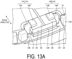
- FIG. 13A is an enlarged perspective view of a connection portion in a second modification example of the embodiment.
- FIG. 13B is an enlarged side view of the connection portion.
- a motor according to the second modification example of the embodiment is different from the above first modification example, and in the second modification example, the first end part 141 and the second end part 142 of the conducting wire 14 each have a bent portion and a deformed portion.
- the first end part 141 of the conducting wire 14 includes a first deformed portion 145 having a cross-sectional shape different from the cross-sectional shape of the conducting wire 14 in the assembled state with the substrate 2 assembled to the stator 1.
- the first deformed portion 145 is formed in a rectangular shape when viewed from the axial direction, and is located at the second bent portion 144 side with respect to the first bent portion 143.
- the first deformed portion 145 is, for example, a portion crushed in the circumferential direction before the first end part 141 is bent at the first bent portion 143.
- the second end part 142 of the conducting wire 14 includes a second deformed portion 146 having a cross-sectional shape different from the cross-sectional shape of the conducting wire 14 in the assembled state with the substrate 2 assembled to the stator 1.
- the second deformed portion 146 is formed in a rectangular shape when viewed from the axial direction, and is located at the first bent portion 143 side with respect to the second bent portion 144.
- the second deformed portion 146 is, for example, a portion crushed in the circumferential direction before the second end part 142 is bent at the second bent portion 144.
- the first end part 141 of the conducting wire 14 includes the first deformed portion 145 located at the second bent portion 144 side with respect to the first bent portion 143 and having a cross-sectional shape different from the cross-sectional shape of the conducting wire 14.
- the second end part 142 of the conducting wire 14 includes the second deformed portion 146 located at the first bent portion 143 side with respect to the second bent portion 144 and having a cross-sectional shape different from the cross-sectional shape of the conducting wire 14.
- the substrate 2 includes the land 30 electrically connected to the end part of the conducting wire 14 drawn out from the coil 13, and the land 30 is provided at the substrate front surface 20a side; however, the embodiment is not limited to the configuration.
- FIG. 14A is an enlarged perspective view of a substrate recess part in a third modification example of the embodiment.
- FIG. 14B is an enlarged plan view of a front surface side of the substrate recess part.
- FIG. 14C is an enlarged plan view of a rear surface side of the substrate recess part.
- FIG. 15 is a schematic view illustrating an example of a soldering state of a conducting wire to the substrate recess part in the third modification example of the embodiment.
- a motor according to the third modification example of the embodiment is different from the above embodiment, and in the third modification example, the land 30 is formed not only at the front surface side and the rear surface side of the substrate body 20 but also at the inner peripheral surface of each recess part.
- the land 30 includes a first land portion 31, a second land portion 32, and a third land portion 33.
- the first land portion 31 is disposed at one end surface of the substrate 2 in a thickness direction. Specifically, as illustrated in FIGS. 14A and 14B , the first land portion 31 is disposed at the front surface side of the substrate body 20 along each of the substrate-side first recess part 21 and the substrate-side second recess part 22.
- the second land portion 32 is disposed at the other end surface of the substrate 2 in the thickness direction. Specifically, as illustrated in FIG. 14C , the second land portion 32 is disposed at the rear surface side of the substrate body 20 along each of the substrate-side first recess part 21 and the substrate-side second recess part 22. As illustrated in FIGS.
- the third land portion 33 is disposed at the inner peripheral surface of each of the substrate-side first recess part 21 and the substrate-side second recess part 22.
- the first land portion 31, the second land portion 32, and the third land portion 33 communicate with one another.
- the first land portion 31, the second land portion 32, and the third land portion 33 are continuously formed and electrically connected to one another.
- the first land portion 31 in the third modification example of the present embodiment has a larger area than the third land portion 33.
- the second land portion 32 has a smaller area than the first land portion 31.
- the first end part 141 of the conducting wire 14 is passed through the inside of the substrate-side first recess part 21 in a state of being inclined toward the substrate-side second recess part 22 in the circumferential direction, in the assembled state with the substrate 2 assembled to the stator 1.
- the second end part 142 of the conducting wire 14 is passed through the inside of the substrate-side second recess part 22 in a state of being inclined toward the substrate-side first recess part 21 in the circumferential direction, in the assembled state with the substrate 2 assembled to the stator 1. As illustrated in FIG.
- the outer peripheral surfaces of the first end part 141 and the second end part 142 of the conducting wire 14 are in contact with and supported by a peripheral end at the substrate front surface 20a side and a peripheral end at a substrate rear surface 20b side of the recess parts (the substrate-side first recess part 21 and the substrate-side second recess part 22). Therefore, relative movement of the end parts of the conducting wire 14 being a draw wire with respect to the substrate 2 can be suppressed.
- the substrate-side first recess part 21 and the substrate-side second recess part 22 are recessed at the inside in the radial direction from the outer peripheral end and open at the outside in the radial direction.
- the end parts of the conducting wire 14 can be wired at the inside of the substrate-side first recess part 21 and the substrate-side second recess part 22 from the radial direction instead of the axial direction (direction orthogonal to the substrate surface). Therefore, the conducting wire 14 can be easily assembled to the substrate 2 and productivity can be improved.
- the third land portion 33 is disposed at the inner peripheral surface of each of the substrate-side first recess part 21 and the substrate-side second recess part 22, and the first land portion 31, the second land portion 32, and the third land portion 33 communicate with one another.
- the land 30 and the conducting wire 14 are soldered to each other, not only the first land portion 31 and the conducting wire 14 can be joined, but also the second land portion 32, the third land portion 33 and the conducting wire 14 can be joined.
- the strength of a join part between the land 30 and the conducting wire 14 can be improved, and since the conducting wire 14 being a draw wire from the coil 13 is widely connected in the thickness direction of the substrate 2, relative movement between the substrate 2 and the conducting wire 14 due to, for example, vibration or the like of the motor can be suppressed, and disconnection or the like of the conducting wire 14 can be prevented.
- the first end part 141 is disposed at the inside of the substrate-side first recess part 21 in a state of being inclined toward the substrate-side second recess part 22 in the circumferential direction
- the second end part 142 is disposed at the inside of the substrate-side second recess part 22 in a state of being inclined toward the substrate-side first recess part 21 in the circumferential direction; however, the embodiment is not limited to the configuration.
- the third modification example of the embodiment may be applied to the first modification example and the second modification example of the embodiment.
- the end part of the conducting wire 14 is soldered and fixed at the substrate 2 at three points by using solder flowing into the third land portion 33 and the second land portion 32 in the order; however, the embodiment is not limited to the configuration.
- the end part of the conducting wire 14 may be soldered and fixed at the substrate 2 at two points by using solder flowing into the third land portion 33.
- the end part of the conducting wire 14 may be soldered and fixed at the substrate 2 at three points by using solder flowing into the third land portion 33.
- the wall part 122 of the insulator 12 includes two recess parts (the insulator-side first recess part 126 and the insulator-side second recess part 127) opposed to two drawing positions of the conducting wire 14 drawn out from the coil 13 in the radial direction; however, the embodiment is not limited to the configuration.
- FIG. 16 is an external perspective view of a segment core in a fourth modification example of the embodiment.
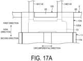
- FIG. 17A is an enlarged side view of a connection portion between the segment core and a substrate in the fourth modification example of the embodiment.
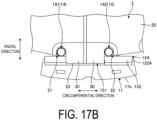
- FIG. 17B is an enlarged plan view of the connection portion in the fourth modification example of the embodiment.
- FIG. 18 is a schematic view illustrating a change in the position of a conducting wire when the substrate is assembled to the segment core in the fourth modification example of the embodiment.
- a motor according to the fourth modification example of the embodiment is different from the above embodiment, and in the fourth modification example, a wall part 122A of an insulator 12A includes an inclined surface 152.
- the insulator 12 includes the accommodation part 121 and a wall part 122A formed at an end part at the outside in the radial direction of the accommodation part 121.
- the wall part 122A is located at the outer peripheral side of the substrate 2 in the assembled state with the substrate 2 assembled to the stator 1.
- the wall part 122A is formed in a substantially rectangular shape, and is formed to protrude from the yoke part 11b in the axial direction.
- the wall part 122A includes a recess part 151 and the inclined surface 152.
- the recess part 151 is formed to be recessed from an end part of the wall part 122A at the side of the first direction in the axial direction toward the side of the second direction.
- the recess part 151 is a portion fitted with the substrate protruding part 23 in the assembled state with the substrate 2 assembled to the stator 1.
- the inclined surface 152 is inclined to be thinner in the radial direction from the middle of the wall part 122A in the axial direction toward the end part of the wall part 122A at the side of the first direction.
- the inclined surface 152 is also inclined from the inner side to the outer side in the radial direction toward the drawing direction of the conducting wire 14 in the assembled state with the substrate 2 assembled to the stator 1.
- the insulator 12A includes the wall part 122A located at the outer peripheral side of the substrate 2 in the assembled state with the substrate 2 assembled to the stator 1.
- the wall part 122A includes the inclined surface 152 inclined from the inner side to the outer side in the radial direction toward the drawing direction of the conducting wire 14 in the assembled state with the substrate 2 assembled to the stator 1.
- the end parts of the conducting wire 14 escaped to the inclined surface 152 side of the insulator 12A can be inserted into the recess parts (the substrate-side first recess part 21 and the substrate-side second recess part 22) at the substrate 2 side.
- the stator 1 and the substrate 2 can be assembled without the conducting wire 14 interfering with the insulator 12A, and the productivity of the motor can be improved.
- the plurality of recess parts 130 are formed to be recessed from the outer surface 125 toward the side of the second direction in the axial direction; however, the embodiment is not limited to the configuration and the plurality of recess parts 130 may be formed to protrude from the outer surface 125 toward the side of the first direction in the axial direction.
- one of the four outer surfaces 125 includes the plurality of recess parts 130 and the flat surface 131; however, the embodiment is not limited to the configuration. For example, all of the four outer surfaces 125 may each include the plurality of recess parts 130 and the flat surface 131.
- the outer surface 125 formed by the plurality of recess parts 130 and the flat surface 131 may be applied to all of the four outer surfaces 125 constituting the outer peripheral surface of the accommodation part 121 or may be applied to a part of the outer surface 125.
- a coil is formed by winding a conducting wire around a stator core via an insulator being an insulating body.
- Some insulators have a plurality of guide grooves at an outer peripheral surface in order to uniformly wind the coil.
- the conducting wire is wound around the outer peripheral surface of the insulator, the conducting wire is layered in the radial direction of the stator core, resulting in an increase in the outer diameter of the coil. Therefore, since the distance between the inside portions of coils in the radial direction wound around stator cores adjacent to each other in the circumferential direction becomes short, the coils may come into contact with each other.
- contact between coils wound around stator cores adjacent to each other in the circumferential direction can be suppressed.
- a motor includes a plurality of stator cores, and both ends of a conducting wire wound around each stator core are physically and electrically connected to a connection member such as a bus bar or a substrate.
- a connection member such as a bus bar or a substrate.
- the connection member is a substrate
- the substrate is moved in the circumferential direction with respect to the stator due to vibration or the like of the motor, and a load is applied to the conducting wire arranged between the stator and the substrate, so the configuration needs to be improved.
- a load applied to the conducting wire arranged between the stator and the substrate can be reduced.
- a motor includes a plurality of stator cores, and both ends of a conducting wire wound around each stator core are physically and electrically connected to a connection member such as a bus bar or a substrate.
- a connection member such as a bus bar or a substrate.
- the connection member is a substrate, for example, since the end part of the conducting wire is passed through a through hole provided at the substrate and then is soldered and connected to a land on the substrate, the configuration needs to be improved in terms of the assemblability of the conducting wire with respect to the substrate.
- the assemblability of the conducting wire with respect to the substrate can be improved.
Landscapes
- Engineering & Computer Science (AREA)
- Power Engineering (AREA)
- Insulation, Fastening Of Motor, Generator Windings (AREA)
Abstract
Description
- The present invention relates to a motor.
- In the related art, a motor includes a plurality of stator cores, and both ends of a conducting wire wound around each stator core are physically and electrically connected to a connection member such as a bus bar or a substrate (for example, see PTL 1).
- PTL 1:
JP 2011-205877 A - However, in a case where the connection member is a substrate, for example, when a conducting wire (hereinafter, also referred to as a "draw wire") drawn out from a coil is routed to the substrate disposed at the stator core, since the draw wire interferes with a wall part of an insulator, routing of the conducting wire is not easy, and the configuration needs to be improved in terms of the assemblability of the conducting wire with respect to the substrate.
- An object of the present invention is to provide a motor capable of improving the assemblability of a conducting wire with respect to a substrate.
- A motor according to an aspect of the present invention includes a stator including a magnetic body, an insulator surrounding the magnetic body, and a coil formed of a conducting wire wound around the magnetic body via the insulator, and a substrate having an annular shape provided at the stator, wherein, of two drawing positions of the conducting wire drawn out from the coil, one drawing position is in an outer peripheral portion of the coil and the other drawing position is at an inside of the outer peripheral portion. The substrate includes a first recess part and a second recess part recessed at the inside in a radial direction from an outer peripheral end and adjacent to each other in a circumferential direction, the insulator includes a wall part located at an outer peripheral side of the substrate in an assembled state with the substrate assembled to the stator, the wall part includes a third recess part opposed to one of the two drawing positions of the conducting wire and a fourth recess part opposed to the other of the two drawing positions of the conducting wire, the first recess part is opposed to the third recess part, and the second recess part is opposed to the fourth recess part.
- According to an aspect of the present invention, the assemblability of a conducting wire with respect to a substrate can be improved.
- Furthermore, a motor according to another aspect of the present invention includes a coil formed of a conducting wire; and an insulator including an outer surface surrounded by the coil, wherein the outer surface of the insulator includes a plurality of recess parts and a flat surface, and parts of the conducting wire opposed to the flat surface are spaced from parts of the conducting wire fitted into the plurality of recess parts.
- According to another aspect of the present invention, contact between coils wound around stator cores adjacent to each other in a circumferential direction can be suppressed.
- A motor according to further another aspect of the present invention includes: a stator including a magnetic body and a conducting wire wound around the magnetic body; and a substrate having an annular shape provided at the stator, wherein the substrate includes a first recess part and a second recess part recessed at an inside in a radial direction from an outer peripheral end and adjacent to each other in a circumferential direction, and, of two end parts of the conducting wire, a first end part is located at an inside of the first recess part and a second end part is located at an inside of the second recess part, and
the first end part and the second end part are disposed in a direction opposing each other in the circumferential direction. - According to further another aspect of the present invention, a load applied to a conducting wire arranged between a stator and a substrate can be reduced.
- A motor according to a still another aspect of the present invention includes: a stator including a magnetic body and a conducting wire wound around the magnetic body; and a substrate having an annular shape provided at the stator, wherein the substrate includes one or more recess parts recessed at an inside in a radial direction from an outer peripheral end, and a land having conductivity and connected to the conducting wire, an end part of the conducting wire being disposed at an inside of the recess part, the land includes a first land disposed at a front surface side of the substrate along the recess part, a second land disposed at a rear surface side of the substrate along the recess part, and a third land disposed at an inner peripheral surface of the recess part, and the first land, the second land, and the third land communicate with one another.
- According to still another aspect of the present invention, the assemblability of a conducting wire with respect to a substrate can be improved.
-
-
FIG. 1 is an external perspective view of a stator according to an embodiment. -
FIG. 2 is a partially exploded perspective view of the stator according to the embodiment. -
FIG. 3 is a vertical sectional view of the stator according to the embodiment. -
FIG. 4 is an external perspective view of a segment core constituting the stator. -
FIG. 5 is an enlarged plan view of a connection portion between the segment core and a substrate. -
FIG. 6 is a partially exploded perspective view of the segment core. -
FIG. 7 is a schematic cross-sectional view of an insulator and a coil constituting the segment core. -
FIG. 8 is a schematic cross-sectional view of adjacent segment cores. -
FIG. 9 is a vertical sectional view of the insulator. -
FIG. 10 is a schematic view illustrating a change in a position of a conducting wire when the substrate is assembled to the segment core. -
FIG. 11A is an enlarged side view of the connection portion between the segment core and the substrate. -
FIG. 11B is a schematic view illustrating an example of a soldering state of the conducting wire to a substrate recess part. -
FIG. 12A is an enlarged plan view of a connection portion in a first modification example of the embodiment. -
FIG. 12B is an enlarged side view of the connection portion. -
FIG. 13A is an enlarged perspective view of a connection portion in a second modification example of the embodiment. -
FIG. 13B is an enlarged side view of the connection portion. -
FIG. 14A is an enlarged perspective view of a substrate recess part in a third modification example of the embodiment. -
FIG. 14B is an enlarged plan view of a front surface side of the substrate recess part. -
FIG. 14C is an enlarged plan view of a rear surface side of the substrate recess part. -
FIG. 15 is a schematic view illustrating an example of a soldering state of a conducting wire to the substrate recess part in the third modification example of the embodiment. -
FIG. 16 is an external perspective view of a segment core in a fourth modification example of the embodiment. -
FIG. 17A is an enlarged side view of a connection portion between the segment core and a substrate in the fourth modification example of the embodiment. -
FIG. 17B is an enlarged plan view of the connection portion in the fourth modification example of the embodiment. -
FIG. 18 is a schematic view illustrating a change in a position of a conducting wire when the substrate is assembled to the segment core in the fourth modification example of the embodiment. - An embodiment of the present invention is described below with reference to the drawings. Note that the present invention is not limited by the following embodiment. Furthermore, the dimensional relationships between elements, proportions of the elements, and the like in the drawings may differ from reality. The drawings may each include parts having mutually different dimensional relationships and proportions. Furthermore, the contents described in one embodiment or modification example are applied in principle to other embodiments or modification examples.
-
FIG. 1 is an external perspective view of a stator according to an embodiment.FIG. 2 is a partially exploded perspective view of a stator according to the embodiment.FIG. 3 is a vertical sectional view of the stator according to the embodiment.FIG. 4 is an external perspective view of a segment core constituting the stator.FIG. 5 is an enlarged plan view of a connection portion between the segment core and a substrate.FIG. 6 is a partially exploded perspective view of the segment core.FIG. 7 is a schematic cross-sectional view of an insulator and a coil constituting the segment core.FIG. 8 is a schematic cross-sectional view of adjacent segment cores.FIG. 9 is a vertical sectional view of the insulator.FIG. 10 is a schematic view illustrating a change in a position of a conducting wire when the substrate is assembled to the segment core.FIG. 11A is an enlarged side view of the connection portion between the segment core and the substrate.FIG. 11B is a schematic view illustrating an example of a soldering state of the conducting wire to a substrate recess part. - Note that in the following description, for convenience, the axial direction in the illustration is a rotational axis direction of the motor of the present embodiment. In the axial direction, one direction is a first direction and the other direction is a second direction. The radial direction illustrated in the drawing is the radial direction orthogonal to the rotational axis direction of the motor of the present embodiment. In the radial direction, a direction away from a rotational axis X illustrated is the outside in the radial direction, and the direction toward the rotational axis X is the inside in the radial direction. The circumferential direction illustrated in the drawing is a direction coinciding with the rotational direction of the motor of the present embodiment.
- A
stator 1 according to the present embodiment is applied to, for example, an inner rotor type brushless motor or the like. A motor of the present embodiment includes an inner rotor as a rotor, a shaft fixed at the inner rotor, thestator 1 having a coil and a magnetic body wound around with the coil, and asubstrate 2 having an annular shape provided at thestator 1. The motor employing thestator 1 is not limited to a brushless motor. - The
stator 1 illustrated inFIG. 1 is disposed to surround the inner rotor (not illustrated). As illustrated inFIG. 4 , thestator 1 includes a plurality ofsegment cores 10 as so-called segment cores. Thestator 1 is formed by disposing the plurality ofsegment cores 10 along the circumferential direction in an annular shape and joining and integrating theadjacent segment cores 10. As illustrated inFIG. 2 , in thestator 1, thesubstrate 2 formed in an annular shape is disposed at the side of the first direction in the axial direction. The plurality ofsegment cores 10 are integrated by insert molding while being disposed along the circumferential direction in an annular shape, for example. - As illustrated in
FIGS. 3 and4 , thesegment core 10 includes astator core 11, aninsulator 12, and acoil 13 surrounding thestator core 11 via theinsulator 12. - The
stator core 11 is a magnetic body having a layered structure obtained by layering a plurality of electromagnetic steel plates and the like, for example. A plurality of thestator cores 11 is disposed along the circumferential direction in an annular shape. Thestator core 11 includes atooth part 11a and ayoke part 11b. Thetooth part 11a extends to the inside in the radial direction from an inner peripheral side of theyoke part 11b. As illustrated inFIG. 8 , theyoke part 11b is connected to theadjacent yoke part 11b in the circumferential direction, with the plurality ofsegment cores 10 disposed along the circumferential direction in an annular shape. - The
insulator 12 is formed of, for example, an insulating body and is interposed between thestator core 11 and thecoil 13 to electrically insulate thecoil 13 and thestator core 11. As illustrated inFIG. 6 , theinsulator 12 includes anaccommodation part 121 accommodating thestator core 11 inside, and awall part 122 formed at an end part at the outside in the radial direction of theaccommodation part 121. Theinsulator 12 is formed to be divided into two parts, and can accommodate thestator core 11 inside in the divided state. - The
wall part 122 is located at the outer peripheral side of thesubstrate 2 in an assembled state with thesubstrate 2 assembled to thestator 1. When viewed from the radial direction, thewall part 122 is formed in a substantially rectangular shape, and is formed to protrude from theyoke part 11b in the axial direction. Thewall part 122 includes two recess parts in the radial direction opposed to the drawing positions of two conductingwires 14 drawn out from thecoil 13. Specifically, as illustrated inFIG. 9 , thewall part 122 includes an insulator-sidefirst recess part 126 and an insulator-sidesecond recess part 127. - The insulator-side first recess part 126 (third recess part) is formed corresponding to one of the drawing positions of the
conducting wire 14, and the oneconducting wire 14 is disposed at the inside along the direction intersecting the extending direction of the oneconducting wire 14. The insulator-side second recess part 127 (fourth recess part) is formed corresponding to the other of the drawing positions of theconducting wire 14, and theother conducting wire 14 is disposed at the inside along the direction intersecting the extending direction of theother conducting wire 14. As illustrated inFIGS. 5 and11A , the insulator-sidefirst recess part 126 and the insulator-sidesecond recess part 127 are formed at thesegment core 10 at positions opposed to the drawing positions of theconducting wire 14 drawn from thecoil 13. Specifically, the insulator-sidefirst recess part 126 is formed at thesegment core 10 at a position opposed to afirst end part 141 of theconducting wire 14 drawn out from thecoil 13. The insulator-sidesecond recess part 127 is formed at thesegment core 10 at a position opposed to asecond end part 142 of theconducting wire 14 drawn out from thecoil 13. An insulator-side protruding part 128 is formed between the insulator-sidefirst recess part 126 and the insulator-sidesecond recess part 127 in the circumferential direction. The insulator-side protruding part 128 extends outward without protruding from an end part of thewall part 122 in the first direction in the axial direction. The insulator-side protruding part 128 is opposed to asubstrate protruding part 23 in the axial direction in the assembled state with thesubstrate 2 assembled to thestator 1. - The insulator-side
first recess part 126 and the insulator-sidesecond recess part 127 are opposed to a substrate-sidefirst recess part 21 and a substrate-sidesecond recess part 22 of thesubstrate 2, respectively, in the assembled state with thesubstrate 2 assembled to thestator 1. Specifically, the insulator-sidefirst recess part 126 is opposed to the substrate-sidefirst recess part 21 in the assembled state with thesubstrate 2 assembled to thestator 1. The insulator-sidesecond recess part 127 is opposed to the substrate-sidesecond recess part 22 in the assembled state with thesubstrate 2 assembled to thestator 1. The insulator-sidefirst recess part 126 and the insulator-sidesecond recess part 127 form a space for allowing thefirst end part 141 and thesecond end part 142 of theconducting wire 14 to be escaped at the outside in the radial direction when theconducting wire 14 drawn out from thecoil 13 is connected to thesubstrate 2. The substrate-sidefirst recess part 21 and the substrate-sidesecond recess part 22 of thesubstrate 2 form a space for joining thefirst end part 141 and thesecond end part 142 of theconducting wire 14 to thesubstrate 2 side when theconducting wire 14 drawn out from thecoil 13 is connected to thesubstrate 2. - The
accommodation part 121 is formed in a rectangular tubular shape when viewed along the radial direction, and thetooth part 11a is accommodated at an inside of theaccommodation part 121 in an assembled state with theinsulator 12 assembled to the stator core 11 (FIG. 6 ). Theaccommodation part 121 includes fourouter surfaces 125 at an outer peripheral surface of theaccommodation part 121. Theouter surface 125 is wound around with theconducting wire 14. Theouter surface 125 is surrounded by a plurality of layers ofcoil 13. As illustrated inFIGS. 7 and8 , theouter surface 125 of the present embodiment is surrounded by two layers of thecoil 13. Among the fourouter surfaces 125, two surfaces at both sides in the circumferential direction are each formed by only flat surfaces, and two surfaces at both sides in the axial direction are each formed by a plurality ofrecess parts 130 and aflat surface 131. Although the plurality of recess parts and theflat surface 131 are formed at the two surfaces in the present embodiment, the plurality of recess parts and theflat surface 131 may be formed at at least one surface. - The plurality of
recess parts 130 are formed at the outside in the radial direction at two surfaces at both sides in the axial direction among the fourouter surfaces 125 of theaccommodation part 121. Therecess parts 130 are continuously disposed along the radial direction. Eachrecess part 130 is, for example, a part protruding toward the side of the first direction in the axial direction and is surrounded by two protrudingparts 132 adjacent to each other in the radial direction. Theconducting wire 14 wound around theinsulator 12 is stored in eachrecess part 130. As illustrated inFIG. 7 , the positions of theconducting wire 14 wound around the plurality ofrecess parts 130 are regulated by therespective recess parts 130, and theconducting wire 14 is evenly disposed in a lattice shape along thetooth part 11a of thestator core 11. - The
flat surface 131 is formed at the inside in the radial direction at two surfaces at both sides in the axial direction among the fourouter surfaces 125 of the accommodation part 121 (FIG. 7 ). Theflat surface 131 is formed at the inside in the radial direction of theouter surface 125 having the plurality ofrecess parts 130 formed at the outside in the radial direction, and is a flat surface having norecess parts 130. The length of theflat surface 131 in the radial direction is set to be longer than the length of an outer diameter of theconducting wire 14. - Parts of the
conducting wire 14 wound around theflat surface 131 are spaced in the radial direction between adjacent conductingwires 14 in a first layer of thecoil 13. Specifically,adjacent conducting wire 14a andconducting wire 14b of the first layer of thecoil 13 are not in contact with each other but are spaced from each other in the radial direction (FIG. 7 ). On the other hand, in the first layer of thecoil 13, parts of theconducting wire 14 fitted into the plurality ofrecess parts 130 are not spaced from each other in the radial direction between theadjacent conducting wires 14, but are in contact with each other. - Parts of the
conducting wire 14 opposed to twoflat surfaces 131 of twoinsulators 12 adjacent to each other in the circumferential direction face each other. Specifically, as illustrated inFIG. 8 , in the twoadjacent insulators 12, theconducting wire 14a to theconducting wire 14c opposed to theflat surface 131 of one of the twoadjacent insulators 12 face theconducting wire 14a to theconducting wire 14c opposed to theflat surface 131 of theother insulator 12 in the circumferential direction. - Other parts of the
conducting wire 14 stacked at parts of theconducting wire 14 opposed to theflat surface 131 are disposed at the inside in the circumferential direction with respect to other parts of theconducting wire 14 stacked at parts of theconducting wire 14 fitted into the plurality ofrecess parts 130. Specifically, as illustrated inFIG. 7 , theconducting wire 14b of the ninth turn of the first layer of thecoil 13 is wound to move to the inside in the radial direction, and theconducting wire 14c of the tenth turn being the first winding of the second layer is wound to be disposed at the inside in the circumferential direction (for example, at the side of the second direction in the axial direction) more than usual. In other words, the maximum height in the axial direction of theconducting wire 14c at the second layer side layered at theflat surface 131 is lower than the maximum height in the axial direction of theconducting wire 14 at the second layer side layered at therecess part 130 side. The spacing distance in the axial direction between the central axes of theconducting wire 14c at the second layer side and theflat surface 131 is shorter than the spacing distance between the central axes of theconducting wire 14 at the second layer side layered at therecess part 130 side and theouter surface 125. - Parts of the
conducting wire 14 opposed to theflat surface 131 are exposed to the outside with respect to other parts of theconducting wire 14 stacked at parts of theconducting wire 14 fitted into the plurality ofrecess parts 130. Specifically, as illustrated inFIG. 7 , among the conductingwires 14a to 14c opposed to theflat surface 131, theconducting wire 14a is not shielded from the outside by theconducting wire 14c or the like constituting the second layer of thecoil 13, and is visible from the outside. - Parts of the
conducting wire 14 opposed to theflat surface 131 are located away from theouter surface 125 with respect to parts of theconducting wire 14 fitted into the plurality ofrecess parts 130. Specifically, theconducting wire 14c being a part of the conducting wire opposed to theflat surface 131 is stacked between theconducting wire 14a and theconducting wire 14b, and thus is disposed at a position away from theouter surface 125 at the side of the first direction in the axial direction, so that the spacing distance in the case is smaller than the distance from other parts of theconducting wire 14 stacked at parts of theconducting wire 14 fitted into the plurality ofrecess parts 130 to theouter surface 125. - As illustrated in
FIG. 9 , the position in the circumferential direction of one of the insulator-sidefirst recess part 126 and the insulator-sidesecond recess part 127 is located at a position overlapping one (inside in the circumferential direction) of a pair ofouter surfaces 125 opposed to each other in the circumferential direction among the outer surfaces of theaccommodation part 121 when viewed in the radial direction. The position of the other recess part in the circumferential direction is shifted to the outer side in the circumferential direction when viewed from the radial direction with respect to the other (outside in the circumferential direction) of the pair ofouter surfaces 125 opposed to each other in the circumferential direction. - The
coil 13 is formed of theconducting wire 14 wound around thestator core 11 via theinsulator 12. Thecoil 13 is disposed to surround theouter surface 125 of theinsulator 12. Thecoil 13 is wound clockwise or counterclockwise around thetooth part 11a of thestator core 11 via theaccommodation part 121 of theinsulator 12. Thecoil 13 is formed of theconducting wire 14 wound in two layers; however, the embodiment is not limited the configuration. For example, thecoil 13 may be wound with an even number of layers of two or more layers, or may be wound with an odd number of layers of one or more layers. Thefirst end part 141 and thesecond end part 142 of theconducting wire 14 are drawn as draw wires from thecoil 13 in the same direction. Thefirst end part 141 and thesecond end part 142 are both drawn out from thecoil 13 in the first direction of the axial direction. Thefirst end part 141 is drawn out from the outer peripheral portion of thecoil 13, and the drawing position of thefirst end part 141 is at the outer peripheral portion of thecoil 13. Thesecond end part 142 is drawn out from the inner peripheral portion of thecoil 13, and the drawing position of thesecond end part 142 is at the inside of the outer peripheral portion of thecoil 13. - The
substrate 2 is disposed at the side of the first direction in the axial direction of thestator 1. Thesubstrate 2 is formed of a resin material having an insulation property such as epoxy. An electronic component (not illustrated in the drawing) is disposed at thesubstrate 2. Examples of the electronic component include an inverter and a control IC. As illustrated inFIGS. 2 ,5 ,11A , and11B , thesubstrate 2 includes a plurality of substrate-sidefirst recess parts 21 and substrate-sidesecond recess parts 22 recessed at the inside in the radial direction from the outer peripheral end and adjacent to each other in the circumferential direction. - As illustrated in
FIG. 11A , thefirst end part 141 being one end part of theconducting wire 14 drawn from thecoil 13 is passed through the substrate-sidefirst recess part 21, in the assembled state with thesubstrate 2 assembled to thestator 1. As illustrated inFIG. 11A , thesecond end part 142 being the other end part of theconducting wire 14 drawn from thecoil 13 is passed through the substrate-sidesecond recess part 22, in the assembled state with thesubstrate 2 assembled to thestator 1. In the circumferential direction, thesubstrate protruding part 23 is formed between the substrate-sidefirst recess part 21 and the substrate-sidesecond recess part 22. Thesubstrate protruding part 23 is formed to protrude to the outside in the radial direction from the outer periphery of asubstrate body 20. - The
first end part 141 of theconducting wire 14 is located at the inside of the substrate-sidefirst recess part 21 and thesecond end part 142 is located at the inside of the substrate-sidesecond recess part 22, in the assembled state with thesubstrate 2 assembled to thestator 1. Thefirst end part 141 and thesecond end part 142 are disposed in a direction opposing each other in the circumferential direction. Thefirst end part 141 is disposed at the inside of the substrate-sidefirst recess part 21 in a state of being inclined toward the substrate-sidesecond recess part 22 in the circumferential direction. Thesecond end part 142 is disposed at the inside of the substrate-sidesecond recess part 22 in a state of being inclined toward the substrate-sidefirst recess part 21 in the circumferential direction. Thefirst end part 141 and thesecond end part 142 interpose thesubstrate protruding part 23 between the substrate-sidefirst recess part 21 and the substrate-sidesecond recess part 22 in the circumferential direction. As illustrated inFIG. 11B , thefirst end part 141 and thesecond end part 142 are joined to aland 30 of thesubstrate 2 by, for example, a solder H, with thesubstrate protruding part 23 between the substrate-sidefirst recess part 21 and the substrate-sidesecond recess part 22 interposed between thefirst end part 141 and thesecond end part 142 in the circumferential direction. - The
land 30 has conductivity and is connected to theconducting wire 14. As illustrated inFIG. 11B , theland 30 is physically and electrically connected by soldering to thefirst end part 141 and thesecond end part 142 of theconducting wire 14 drawn from thecoil 13. Theland 30 is provided at asubstrate front surface 20a side. - An operation of forming the
coil 13 by winding theconducting wire 14 around theinsulator 12 in the present embodiment is described below. When theconducting wire 14 is wound around theinsulator 12, the first layer of thecoil 13 is wound along the plurality ofrecess parts 130 from the first turn to the eighth turn, and the ninth turn is wound around theflat surface 131. When theconducting wire 14c of the second layer of thecoil 13 is wound from the state so as to be positioned between thewires coil 13 positioned at the innermost side in the radial direction is moved to the inside in the radial direction, and the tenth turn being the first winding of the second layer is wound so as to be positioned at the side of the second direction in the axial direction more than usual. That is, since the position in the radial direction of theconducting wire 14 disposed at theflat surface 131 is not regulated, theconducting wire 14 is moved by the force when theconducting wire 14c of the second layer is wound, and theconducting wire 14c of the second layer is guided to the side of the second direction in the axial direction. At this time, theconducting wire 14b of the first layer of the ninth turn opposed to theflat surface 131 of theinsulator 12 is spaced from theconducting wire 14 of the first to eighth turns opposed to the plurality ofrecess parts 130. Therefore, parts of theconducting wire 14 opposed in the radial direction to theflat surface 131 are spaced from parts of theconducting wire 14 fitted into the plurality ofrecess parts 130. Thus, as illustrated inFIG. 8 , the space between the conductingwires 14 wound aroundadjacent stator cores 11 can be widened, and an electrical short circuit due to contact between theadjacent conducting wires 14c of thecoil 13 can be suppressed. - An operation of drawing the
first end part 141 and thesecond end part 142 of theconducting wire 14 being the draw wire drawn from thecoil 13 in the present embodiment and assembling the drawnfirst end part 141 andsecond end part 142 routed to the substrate-sidefirst recess part 21 and the substrate-sidesecond recess part 22 is described below. When theconducting wire 14 drawn out from thecoil 13 is connected to thesubstrate 2, thefirst end part 141 and thesecond end part 142 of theconducting wire 14 are tilted toward the outside in the radial direction and are caused to escape to the inside of the insulator-sidefirst recess part 126 and the insulator-sidesecond recess part 127 of theinsulator 12. Subsequently, thesubstrate 2 is assembled to thestator 1, and then the end parts of theconducting wire 14 escaped to the inside of the insulator-sidefirst recess part 126 and the insulator-sidesecond recess part 127 are inserted into the inside of the substrate-sidefirst recess part 21 and the substrate-sidesecond recess part 22. Thus, thestator 1 and thesubstrate 2 can be assembled without theconducting wire 14 interfering with theinsulator 12. - As described above, the motor according to an aspect of the present invention includes the
coil 13 formed of theconducting wire 14 and theinsulator 12 having theouter surfaces 125 surrounded by thecoil 13. Theouter surface 125 of theinsulator 12 includes the plurality ofrecess parts 130 and theflat surface 131. Parts of theconducting wire 14 opposed to theflat surface 131 are spaced from parts of theconducting wire 14 fitted into the plurality ofrecess parts 130. For example, when thecoil 13 is formed by winding theconducting wire 14 around theinsulator 12, theconducting wire 14 is wound along the plurality ofrecess parts 130 from the first turn to the eighth turn and is wound around theflat surface 131 at the ninth turn. As a consequence, theconducting wire 14 of the ninth turn in the first layer is moved to the inside in the radial direction, and theconducting wire 14 of the tenth turn being the first winding of the second layer is wound to be disposed at the inside in the circumferential direction (for example, at the side of the second direction in the axial direction) compared to the related art. That is, since the movement, to the inside in the radial direction, of theconducting wire 14 wound around theflat surface 131 is not regulated, theconducting wire 14 is moved by the force when theconducting wire 14 of the tenth turn is wound, and theconducting wire 14 of the tenth turn is guided to the inside in the circumferential direction, so that the size (height) of the inside in the radial direction of thecoil 13 in the circumferential direction is small (low). Thus, contact between thecoils 13 formed at theadjacent insulators 12 can be suppressed. - In the motor according to an aspect of the present invention, parts of the
conducting wire 14 opposed to twoflat surfaces 131 of the twoadjacent insulators 12 face each other in the circumferential direction. Thus, contact between thecoils 13 formed at the twoadjacent insulators 12 can be suppressed. - In the motor according to an aspect of the present invention, other parts of the
conducting wire 14 stacked at parts of theconducting wire 14 opposed to theflat surface 131 are disposed at the inside in the circumferential direction with respect to other parts of theconducting wire 14 stacked at parts of theconducting wire 14 fitted into the plurality ofrecess parts 130. Thus, theconducting wire 14b of the ninth turn of the first layer of thecoil 13 is moved to the inside in the radial direction, and theconducting wire 14c of the tenth turn being the first winding of the second layer is wound to be disposed at the inside in the circumferential direction (for example, at the side of the second direction in the axial direction) more than usual. - In the motor according to an aspect of the present invention, parts of the
conducting wire 14 opposed to theflat surface 131 are exposed to the outside with respect to other parts of theconducting wire 14 stacked at parts of theconducting wire 14 fitted into the plurality ofrecess parts 130. Thus, the conducting wire of the ninth turn of the first layer is moved in the radial direction, and the conducting wire of the tenth turn being the first turn of the second row is more likely to be disposed at the inside in the circumferential direction more than usual. - In the motor according to an aspect of the present invention, parts of the
conducting wire 14 opposed to theflat surface 131 are located away from theouter surface 125 of theinsulator 12 with respect to parts of theconducting wire 14 fitted into the plurality ofrecess parts 130. Thus, theconducting wire 14b of the ninth turn in the first layer of thecoil 13 is easily moved in the radial direction. - As described above, the motor according to an aspect of the present invention includes the
substrate 2 having an annular shape provided at thestator 1. Thesubstrate 2 includes the substrate-sidefirst recess part 21 and the substrate-sidesecond recess part 22 recessed at the inside in the radial direction from the outer peripheral end and adjacent to each other in the circumferential direction. Of the two end parts of theconducting wire 14, thefirst end part 141 is located at the inside of the substrate-sidefirst recess part 21 and thesecond end part 142 is located at the inside of the substrate-sidesecond recess part 22. Thefirst end part 141 and thesecond end part 142 of theconducting wire 14 are disposed in a direction opposing each other in the circumferential direction. Thus, thefirst end part 141 and thesecond end part 142 of theconducting wire 14 can interpose thesubstrate protruding part 23 between the substrate-sidefirst recess part 21 and the substrate-sidesecond recess part 22 in the circumferential direction, so that movement of thesubstrate 2 in the circumferential direction with respect to thestator 1 due to, for example, vibration or the like can be regulated, and a load on theconducting wire 14 arranged between thestator 1 and thesubstrate 2 can be reduced. - In the motor according to an aspect of the present invention, the
first end part 141 is disposed at the inside of the substrate-sidefirst recess part 21 in a state of being inclined toward the substrate-sidesecond recess part 22 in the circumferential direction, and thesecond end part 142 is disposed at the inside of the substrate-sidesecond recess part 22 in a state of being inclined toward the substrate-sidefirst recess part 21 in the circumferential direction. Thefirst end part 141 and thesecond end part 142 interpose thesubstrate protruding part 23 between the substrate-sidefirst recess part 21 and the substrate-sidesecond recess part 22 in the circumferential direction. - As described above, in the motor according to an aspect of the present invention, the
insulator 12 includes thewall part 122 having two recess parts (the insulator-sidefirst recess part 126 and the insulator-side second recess part 127) opposed to two drawing positions of theconducting wire 14 drawn out from thecoil 13 in the radial direction. One of the two drawing positions is located at the outer peripheral portion of thecoil 13, and the other is located at the inside of the outer peripheral portion. Thesubstrate 2 includes the substrate-sidefirst recess part 21 and the substrate-sidesecond recess part 22 recessed at the inside in the radial direction from the outer peripheral end and adjacent to each other in the circumferential direction. The substrate-sidefirst recess part 21 is opposed to the insulator-sidefirst recess part 126, and the substrate-sidesecond recess part 22 is opposed to the insulator-sidesecond recess part 127. - With such a configuration, when the
conducting wire 14 drawn out from thecoil 13 is connected to thesubstrate 2, end parts (thefirst end part 141 and the second end part 142) of theconducting wire 14 can be escaped to recess parts (the insulator-sidefirst recess part 126 and the insulator-side second recess part 127) of theinsulator 12 located at the outside in the radial direction. Subsequently, after thesubstrate 2 is assembled to thestator 1, the end parts of theconducting wire 14 escaped to the recess part of theinsulator 12 can be inserted into recess parts - (the substrate-side
first recess part 21 and the substrate-side second recess part 22) at thesubstrate 2 side. As a consequence, thestator 1 and thesubstrate 2 can be assembled without theconducting wire 14 interfering with theinsulator 12, and the productivity of the motor can be improved. - In the motor according to an aspect of the present invention, as illustrated in
FIG. 9 , the position in the circumferential direction of one of the insulator-sidefirst recess part 126 and the insulator-sidesecond recess part 127 is located at a position overlapping one (inside in the circumferential direction) of a pair ofouter surfaces 125 opposed to each other in the circumferential direction among the outer surfaces of theaccommodation part 121 when viewed in the radial direction. The position of the other recess part in the circumferential direction is shifted to the outside in the circumferential direction when viewed from the radial direction with respect to the other (outside in the circumferential direction) of the pair ofouter surfaces 125 opposed to each other in the circumferential direction. - The insulator-side
second recess part 127 is formed at a position aligned with one (inside in the circumferential direction) of theouter surface 125 at both ends in the circumferential direction of theaccommodation part 121 of theinsulator 12 so that theconducting wire 14 at the start of winding of thecoil 13 comes in and out. On the other hand, the insulator-sidefirst recess part 126 is formed at the outside in the circumferential direction of one conducting wire from a position aligned with the other (outside in the circumferential direction) of theouter surface 125 at both ends in the circumferential direction of theaccommodation part 121 of theinsulator 12 so that the conducting wire 14 (conductingwire 14 of the second layer in the present embodiment) at the end of winding of thecoil 13 comes in and out. With such a configuration, when theconducting wire 14 drawn out from thecoil 13 is connected to thesubstrate 2, the end parts (thefirst end part 141 and the second end part 142) of theconducting wire 14 can be escaped to the recess parts (the insulator-sidefirst recess part 126 and the insulator-side second recess part 127) of theinsulator 12 located at the outside in the radial direction. Therefore, thestator 1 and thesubstrate 2 can be assembled without theconducting wire 14 interfering with theinsulator 12, and the productivity of the motor can be improved. - In the above embodiment, the
first end part 141 of theconducting wire 14 is disposed at the inside of the substrate-sidefirst recess part 21 in a state of being inclined toward the substrate-sidesecond recess part 22 in the circumferential direction, and thesecond end part 142 of theconducting wire 14 is disposed at the inside of the substrate-sidesecond recess part 22 in a state of being inclined toward the substrate-sidefirst recess part 21 in the circumferential direction; however, the embodiment is not limited to the configuration.FIG. 12A is an enlarged plan view of a connection portion in a first modification example of the embodiment.FIG. 12B is an enlarged side view of the connection portion. A motor according to the second modification example of the embodiment is different from the above embodiment, and in the second modification example, thefirst end part 141 and thesecond end part 142 of theconducting wire 14 each have a bent portion. - As illustrated in
FIGS. 12A and12B , thefirst end part 141 of theconducting wire 14 includes a firstbent portion 143 in the assembled state with thesubstrate 2 assembled to thestator 1. Thesecond end part 142 of theconducting wire 14 includes a secondbent portion 144 in the assembled state with thesubstrate 2 assembled to thestator 1. The firstbent portion 143 and the secondbent portion 144 are bent in a direction opposing each other. The firstbent portion 143 is formed at a portion of thefirst end part 141 of theconducting wire 14 drawn out straight from thecoil 13 toward the side of first direction in the axial direction, the portion protruding from the inside of the substrate-sidefirst recess part 21 to the outside of the first direction side. The firstbent portion 143 is bent from the substrate-sidefirst recess part 21 toward the substrate-sidesecond recess part 22 with thesubstrate protruding part 23 interposed between the substrate-sidefirst recess part 21 and the substrate-sidesecond recess part 22 in the circumferential direction of thesubstrate 2. The secondbent portion 144 is formed at a portion of thesecond end part 142 of theconducting wire 14 drawn out straight from thecoil 13 toward the side of the first direction in the axial direction, the portion protruding from the inside of the substrate-sidesecond recess part 22 to the outside of the first direction side. The secondbent portion 144 is bent from the substrate-sidesecond recess part 22 toward the substrate-sidefirst recess part 21 with thesubstrate protruding part 23 interposed between the substrate-sidesecond recess part 22 and the substrate-sidefirst recess part 21 in the circumferential direction of thesubstrate 2. - In the motor according to an aspect of the present invention, the
first end part 141 of theconducting wire 14 drawn out from thecoil 13 includes the firstbent portion 143 bent in the circumferential direction of thesubstrate 2 at a portion protruding from the inside of the substrate-sidefirst recess part 21 to the outside. Thesecond end part 142 of theconducting wire 14 includes the secondbent portion 144 bent in the circumferential direction of thesubstrate 2 at a portion protruding from the inside of the substrate-sidesecond recess part 22 to the outside. The firstbent portion 143 and the secondbent portion 144 are bent in a direction opposing each other. As described above, thefirst end part 141 and thesecond end part 142 of theconducting wire 14 include the firstbent portion 143 and the secondbent portion 144 bent at the inside in the circumferential direction so as to oppose each other, respectively, so that thesubstrate protruding part 23 is held in the circumferential direction. Thus, when theconducting wire 14 is drawn out from thecoil 13, thefirst end part 141 and thesecond end part 142 need not be inclined and drawn out, making it possible to more easily connect theconducting wire 14 and thesubstrate 2. - In the first modification example of the above embodiment, the
first end part 141 and thesecond end part 142 of theconducting wire 14 each have a bent portion; however, the embodiment is not limited to the configuration.FIG. 13A is an enlarged perspective view of a connection portion in a second modification example of the embodiment.FIG. 13B is an enlarged side view of the connection portion. A motor according to the second modification example of the embodiment is different from the above first modification example, and in the second modification example, thefirst end part 141 and thesecond end part 142 of theconducting wire 14 each have a bent portion and a deformed portion. - As illustrated in
FIGS. 13A and13B , thefirst end part 141 of theconducting wire 14 includes a firstdeformed portion 145 having a cross-sectional shape different from the cross-sectional shape of theconducting wire 14 in the assembled state with thesubstrate 2 assembled to thestator 1. The firstdeformed portion 145 is formed in a rectangular shape when viewed from the axial direction, and is located at the secondbent portion 144 side with respect to the firstbent portion 143. The firstdeformed portion 145 is, for example, a portion crushed in the circumferential direction before thefirst end part 141 is bent at the firstbent portion 143. Thesecond end part 142 of theconducting wire 14 includes a seconddeformed portion 146 having a cross-sectional shape different from the cross-sectional shape of theconducting wire 14 in the assembled state with thesubstrate 2 assembled to thestator 1. The seconddeformed portion 146 is formed in a rectangular shape when viewed from the axial direction, and is located at the firstbent portion 143 side with respect to the secondbent portion 144. The seconddeformed portion 146 is, for example, a portion crushed in the circumferential direction before thesecond end part 142 is bent at the secondbent portion 144. - In the motor according to an aspect of the present invention, the
first end part 141 of theconducting wire 14 includes the firstdeformed portion 145 located at the secondbent portion 144 side with respect to the firstbent portion 143 and having a cross-sectional shape different from the cross-sectional shape of theconducting wire 14. Thesecond end part 142 of theconducting wire 14 includes the seconddeformed portion 146 located at the firstbent portion 143 side with respect to the secondbent portion 144 and having a cross-sectional shape different from the cross-sectional shape of theconducting wire 14. Thus, by crushing and deforming thefirst end part 141 and thesecond end part 142 of theconducting wire 14 in the axial direction, the height in the axial direction of the connection portion can be made lower than the outer diameter of theconducting wire 14. As a consequence, the height in the axial direction of thestator 1 including thesubstrate 2 can be suppressed and the motor can be reduced in size. - In the above embodiment, the
substrate 2 includes theland 30 electrically connected to the end part of theconducting wire 14 drawn out from thecoil 13, and theland 30 is provided at thesubstrate front surface 20a side; however, the embodiment is not limited to the configuration.FIG. 14A is an enlarged perspective view of a substrate recess part in a third modification example of the embodiment.FIG. 14B is an enlarged plan view of a front surface side of the substrate recess part.FIG. 14C is an enlarged plan view of a rear surface side of the substrate recess part.FIG. 15 is a schematic view illustrating an example of a soldering state of a conducting wire to the substrate recess part in the third modification example of the embodiment. A motor according to the third modification example of the embodiment is different from the above embodiment, and in the third modification example, theland 30 is formed not only at the front surface side and the rear surface side of thesubstrate body 20 but also at the inner peripheral surface of each recess part. - The
land 30 includes afirst land portion 31, asecond land portion 32, and athird land portion 33. Thefirst land portion 31 is disposed at one end surface of thesubstrate 2 in a thickness direction. Specifically, as illustrated inFIGS. 14A and14B , thefirst land portion 31 is disposed at the front surface side of thesubstrate body 20 along each of the substrate-sidefirst recess part 21 and the substrate-sidesecond recess part 22. Thesecond land portion 32 is disposed at the other end surface of thesubstrate 2 in the thickness direction. Specifically, as illustrated inFIG. 14C , thesecond land portion 32 is disposed at the rear surface side of thesubstrate body 20 along each of the substrate-sidefirst recess part 21 and the substrate-sidesecond recess part 22. As illustrated inFIGS. 14A to 14C , thethird land portion 33 is disposed at the inner peripheral surface of each of the substrate-sidefirst recess part 21 and the substrate-sidesecond recess part 22. Thefirst land portion 31, thesecond land portion 32, and thethird land portion 33 communicate with one another. Specifically, in each of the substrate-sidefirst recess part 21 and the substrate-sidesecond recess part 22, thefirst land portion 31, thesecond land portion 32, and thethird land portion 33 are continuously formed and electrically connected to one another. Thefirst land portion 31 in the third modification example of the present embodiment has a larger area than thethird land portion 33. Thesecond land portion 32 has a smaller area than thefirst land portion 31. - The
first end part 141 of theconducting wire 14 is passed through the inside of the substrate-sidefirst recess part 21 in a state of being inclined toward the substrate-sidesecond recess part 22 in the circumferential direction, in the assembled state with thesubstrate 2 assembled to thestator 1. Thesecond end part 142 of theconducting wire 14 is passed through the inside of the substrate-sidesecond recess part 22 in a state of being inclined toward the substrate-sidefirst recess part 21 in the circumferential direction, in the assembled state with thesubstrate 2 assembled to thestator 1. As illustrated inFIG. 15 , the outer peripheral surfaces of thefirst end part 141 and thesecond end part 142 of theconducting wire 14 are in contact with and supported by a peripheral end at thesubstrate front surface 20a side and a peripheral end at a substraterear surface 20b side of the recess parts (the substrate-sidefirst recess part 21 and the substrate-side second recess part 22). Therefore, relative movement of the end parts of theconducting wire 14 being a draw wire with respect to thesubstrate 2 can be suppressed. - As described above, in the motor according to an aspect of the present invention, the substrate-side
first recess part 21 and the substrate-sidesecond recess part 22 are recessed at the inside in the radial direction from the outer peripheral end and open at the outside in the radial direction. Thus, unlike a through hole provided at thesubstrate 2, the end parts of theconducting wire 14 can be wired at the inside of the substrate-sidefirst recess part 21 and the substrate-sidesecond recess part 22 from the radial direction instead of the axial direction (direction orthogonal to the substrate surface). Therefore, theconducting wire 14 can be easily assembled to thesubstrate 2 and productivity can be improved. Furthermore, thethird land portion 33 is disposed at the inner peripheral surface of each of the substrate-sidefirst recess part 21 and the substrate-sidesecond recess part 22, and thefirst land portion 31, thesecond land portion 32, and thethird land portion 33 communicate with one another. Thus, when theland 30 and theconducting wire 14 are soldered to each other, not only thefirst land portion 31 and theconducting wire 14 can be joined, but also thesecond land portion 32, thethird land portion 33 and theconducting wire 14 can be joined. Thus, the strength of a join part between theland 30 and theconducting wire 14 can be improved, and since theconducting wire 14 being a draw wire from thecoil 13 is widely connected in the thickness direction of thesubstrate 2, relative movement between thesubstrate 2 and theconducting wire 14 due to, for example, vibration or the like of the motor can be suppressed, and disconnection or the like of theconducting wire 14 can be prevented. - In the third modification example of the above embodiment, the
first end part 141 is disposed at the inside of the substrate-sidefirst recess part 21 in a state of being inclined toward the substrate-sidesecond recess part 22 in the circumferential direction, and thesecond end part 142 is disposed at the inside of the substrate-sidesecond recess part 22 in a state of being inclined toward the substrate-sidefirst recess part 21 in the circumferential direction; however, the embodiment is not limited to the configuration. The third modification example of the embodiment may be applied to the first modification example and the second modification example of the embodiment. - In the third modification example of the above embodiment, by soldering the
first land portion 31 from thesubstrate front surface 20a side, the end part of theconducting wire 14 is soldered and fixed at thesubstrate 2 at three points by using solder flowing into thethird land portion 33 and thesecond land portion 32 in the order; however, the embodiment is not limited to the configuration. For example, by soldering thefirst land portion 31 from thesubstrate front surface 20a side, the end part of theconducting wire 14 may be soldered and fixed at thesubstrate 2 at two points by using solder flowing into thethird land portion 33. Alternatively, by soldering thefirst land portion 31 from thesubstrate front surface 20a side and soldering thesecond land portion 32 from the substraterear surface 20b side, the end part of theconducting wire 14 may be soldered and fixed at thesubstrate 2 at three points by using solder flowing into thethird land portion 33. - In the above embodiment, the
wall part 122 of theinsulator 12 includes two recess parts (the insulator-sidefirst recess part 126 and the insulator-side second recess part 127) opposed to two drawing positions of theconducting wire 14 drawn out from thecoil 13 in the radial direction; however, the embodiment is not limited to the configuration.FIG. 16 is an external perspective view of a segment core in a fourth modification example of the embodiment.FIG. 17A is an enlarged side view of a connection portion between the segment core and a substrate in the fourth modification example of the embodiment.FIG. 17B is an enlarged plan view of the connection portion in the fourth modification example of the embodiment.FIG. 18 is a schematic view illustrating a change in the position of a conducting wire when the substrate is assembled to the segment core in the fourth modification example of the embodiment. A motor according to the fourth modification example of the embodiment is different from the above embodiment, and in the fourth modification example, awall part 122A of aninsulator 12A includes aninclined surface 152. - As illustrated in
FIG. 16 , theinsulator 12 includes theaccommodation part 121 and awall part 122A formed at an end part at the outside in the radial direction of theaccommodation part 121. Thewall part 122A is located at the outer peripheral side of thesubstrate 2 in the assembled state with thesubstrate 2 assembled to thestator 1. When viewed from the radial direction, thewall part 122A is formed in a substantially rectangular shape, and is formed to protrude from theyoke part 11b in the axial direction. As illustrated inFIG. 16 , thewall part 122A includes arecess part 151 and theinclined surface 152. Therecess part 151 is formed to be recessed from an end part of thewall part 122A at the side of the first direction in the axial direction toward the side of the second direction. Therecess part 151 is a portion fitted with thesubstrate protruding part 23 in the assembled state with thesubstrate 2 assembled to thestator 1. When viewed from the circumferential direction, as illustrated inFIG. 18 , theinclined surface 152 is inclined to be thinner in the radial direction from the middle of thewall part 122A in the axial direction toward the end part of thewall part 122A at the side of the first direction. Theinclined surface 152 is also inclined from the inner side to the outer side in the radial direction toward the drawing direction of theconducting wire 14 in the assembled state with thesubstrate 2 assembled to thestator 1. - As described above, in the motor according to an aspect of the present invention, the
insulator 12A includes thewall part 122A located at the outer peripheral side of thesubstrate 2 in the assembled state with thesubstrate 2 assembled to thestator 1. Thewall part 122A includes theinclined surface 152 inclined from the inner side to the outer side in the radial direction toward the drawing direction of theconducting wire 14 in the assembled state with thesubstrate 2 assembled to thestator 1. Thus, when theconducting wire 14 drawn out from thecoil 13 is connected to thesubstrate 2, the end parts (thefirst end part 141 and the second end part 142) of theconducting wire 14 can be escaped to theinclined surface 152 side of theinsulator 12A at the outside in the radial direction. After thesubstrate 2 is assembled to thestator 1, the end parts of theconducting wire 14 escaped to theinclined surface 152 side of theinsulator 12A can be inserted into the recess parts (the substrate-sidefirst recess part 21 and the substrate-side second recess part 22) at thesubstrate 2 side. As a consequence, thestator 1 and thesubstrate 2 can be assembled without theconducting wire 14 interfering with theinsulator 12A, and the productivity of the motor can be improved. - In the above embodiment and modification examples, the plurality of
recess parts 130 are formed to be recessed from theouter surface 125 toward the side of the second direction in the axial direction; however, the embodiment is not limited to the configuration and the plurality ofrecess parts 130 may be formed to protrude from theouter surface 125 toward the side of the first direction in the axial direction. Furthermore, one of the fourouter surfaces 125 includes the plurality ofrecess parts 130 and theflat surface 131; however, the embodiment is not limited to the configuration. For example, all of the fourouter surfaces 125 may each include the plurality ofrecess parts 130 and theflat surface 131. - In the above embodiment and modification examples, among the four outer surfaces of 125 of the
insulator 12, three outer surfaces are formed only by the flat surface and one outer surface is formed by the plurality ofrecess parts 130 and theflat surface 131; however, the embodiment is not limited to the configuration. For example, theouter surface 125 formed by the plurality ofrecess parts 130 and theflat surface 131 may be applied to all of the fourouter surfaces 125 constituting the outer peripheral surface of theaccommodation part 121 or may be applied to a part of theouter surface 125. - In a motor in the related art, for example, a coil is formed by winding a conducting wire around a stator core via an insulator being an insulating body. Some insulators have a plurality of guide grooves at an outer peripheral surface in order to uniformly wind the coil. However, when the conducting wire is wound around the outer peripheral surface of the insulator, the conducting wire is layered in the radial direction of the stator core, resulting in an increase in the outer diameter of the coil. Therefore, since the distance between the inside portions of coils in the radial direction wound around stator cores adjacent to each other in the circumferential direction becomes short, the coils may come into contact with each other. On the other hand, according to an aspect of the present invention, contact between coils wound around stator cores adjacent to each other in the circumferential direction can be suppressed.
- Furthermore, in the related art, a motor includes a plurality of stator cores, and both ends of a conducting wire wound around each stator core are physically and electrically connected to a connection member such as a bus bar or a substrate. However, when the connection member is a substrate, for example, the substrate is moved in the circumferential direction with respect to the stator due to vibration or the like of the motor, and a load is applied to the conducting wire arranged between the stator and the substrate, so the configuration needs to be improved. On the other hand, according to an aspect of the present invention, a load applied to the conducting wire arranged between the stator and the substrate can be reduced.
- In addition, in the related art, a motor includes a plurality of stator cores, and both ends of a conducting wire wound around each stator core are physically and electrically connected to a connection member such as a bus bar or a substrate. However, when the connection member is a substrate, for example, since the end part of the conducting wire is passed through a through hole provided at the substrate and then is soldered and connected to a land on the substrate, the configuration needs to be improved in terms of the assemblability of the conducting wire with respect to the substrate. On the other hand, according to an aspect of the present invention, the assemblability of the conducting wire with respect to the substrate can be improved.
- Although the embodiment and modification examples of the present invention have been described above, the present invention is not limited to the above embodiment and modification examples, and various modifications can be made without departing from the gist of the present invention. Furthermore, the present invention is not limited by the above embodiment and modification examples.
- A configuration obtained by appropriately combining the above-mentioned constituent elements is also included in the present invention. Further effects and modification examples can be easily derived by a person skilled in the art.
- Thus, a wide range of aspects of the present invention are not limited to the above embodiment and various changes can be made.
- 1 Stator, 2 Substrate, 10 Segment core, 11 Stator core, 11a Tooth part, 11b Yoke part, 12 Insulator, 13 Coil, 14 Conducting wire, 20 Substrate body, 21 Substrate-side first recess part, 22 Substrate-side second recess part, 30 Land, 31 First land portion, 32 Second land portion, 33 Third land portion, 121 Accommodation part, 122 Wall part, 125 Outer surface, 126 Insulator-side first recess part (third recess part), 127 Insulator-side second recess part (fourth recess part), 128 Insulator-side protruding part, 130 Recess part, 131 Flat surface, 132 Protruding part, 141 First end part, 142 Second end part, 143 First bent portion, 144 Second bent portion, 145 First deformed portion, 146 Second deformed portion
Claims (17)
- A motor comprising:a stator (1) including a magnetic body (11), an insulator (12) surrounding the magnetic body (11), and a coil (13) formed of a conducting wire (14) wound around the magnetic body (11) via the insulator (12); anda substrate (2) having an annular shape and provided at the stator (1), whereinof two drawing positions of the conducting wire (14) drawn out from the coil (13), one drawing position is at an outer peripheral portion of the coil (13) and the other drawing position is at an inside of the outer peripheral portion,the substrate (2) includes a first recess part (21) and a second recess part (22) recessed at the inside in a radial direction from an outer peripheral end and adjacent to each other in a circumferential direction,the insulator(12) includes a wall part (122) located at an outer peripheral side of the substrate (2) in an assembled state with the substrate (2) assembled to the stator (1),the wall part (122) includes a third recess part (126) opposed to one of the two drawing positions of the conducting wire (14) and a fourth recess part (127) opposed to the other of the two drawing positions of the conducting wire (14),the first recess part (21) is opposed to the third recess part (126), andthe second recess part (22) is opposed to the fourth recess part (127).
- A motor comprising:a stator (1) including a magnetic body (11), an insulator (12) surrounding the magnetic body (11), and a coil (13) formed of a conducting wire (14) wound around the magnetic body (11) via the insulator (12); anda substrate (2) having an annular shape provided at the stator (1), whereinthe insulator (12) includes a wall part (122) located at an outer peripheral side of the substrate (2) in an assembled state with the substrate (2) assembled to the stator (1), andthe wall part (122) includes an inclined surface inclined from an inside to an outside in a radial direction toward a drawing direction of the conducting wire (14) in the assembled state.
- The motor according to claim 1, whereinthe insulator (12) includes an accommodation part (121) including an outer peripheral surface wound around with the conducting wire (14) and accommodating the magnetic body (11) inside,a position in the circumferential direction of one of the third recess part (126) and the fourth recess part (127) is located at a position overlapping one of a pair of the outer surfaces (125) opposing each other in the circumferential direction among the outer peripheral surface of the accommodation part (121) when viewed from the radial direction, anda position of the other recess part in the circumferential direction is shifted to a position at an outside in the circumferential direction when viewed from the radial direction with respect to the other of the pair of the outer surfaces (125) opposed to each other in the circumferential direction.
- A motor comprising:a coil (13) formed of a conducting wire (14); andan insulator (12) including an outer surface (125) surrounded by the coil (13), whereinthe outer surface (125) of the insulator (12) includes a plurality of recess parts (130) and a flat surface (131), andparts of the conducting wire (14) opposed to the flat surface (131) are spaced from parts of the conducting wire (14) fitted into the plurality of recess parts (130).
- The motor according to claim 4, comprising:a plurality of insulators (12) including the insulator (12); anda plurality of coils (13) including the coil (13), whereinparts of the conducting wire (14) opposed to two of the flat surfaces (131) of two adjacent of the insulators (12) oppose each other in a circumferential direction.
- The motor according to claim 4 or 5, wherein
other parts of the conducting wire (14) stacked at parts of the conducting wire (14) opposed to the flat surface (131) are disposed at an inside in the circumferential direction with respect to other parts of the conducting wire (14) stacked at parts of the conducting wire (14) fitted into the plurality of recess parts (130). - The motor according to any one of claims 4 to 6, wherein
parts of the conducting wire (14) opposed to the flat surface (131) are exposed to an outside from other parts of the conducting wire (14) stacked at parts of the conducting wire (14) fitted into the plurality of recess parts (130). - The motor according to any one of claims 4 to 7, wherein
the coil (13) includes an even number of layers formed of the conducting wire (14). - The motor according to any one of claims 4 to 8, wherein
parts of the conducting wire (14) opposed to the flat surface (131) are located away from the outer surface (125) with respect to parts of the conducting wire (14) fitted into the plurality of recess parts (130). - A motor comprising:a stator (1) including a magnetic body (11) and a conducting wire (14) wound around the magnetic body (11); anda substrate (2) having an annular shape provided at the stator (1), whereinthe substrate (2) includes a first recess part (21) and a second recess part (22) recessed at an inside in a radial direction from an outer peripheral end and adjacent to each other in a circumferential direction, andof two end parts of the conducting wire (14), a first end part (141) is located at an inside of the first recess part (21), and a second end part (142) is located at an inside of the second recess part (22), andthe first end part (141) and the second end part (142) are disposed in a direction opposing each other in the circumferential direction.
- The motor according to claim 10, whereinthe first end part is disposed at the inside of the first recess part in a state of being inclined toward the second recess part in the circumferential direction,the second end part is disposed at the inside of the second recess part in a state of being inclined toward the first recess part in the circumferential direction, andthe first end part and the second end part interpose a substrate protruding part between the first recess part and the second recess part in the circumferential direction.
- The motor according to claim 11, whereinthe first end part includes a first bent portion bent in the circumferential direction of the substrate at a portion protruding from an inside of the first recess part to an outside,the second end part includes a second bent portion bent in the circumferential direction of the substrate at a portion protruding from an inside of the second recess part to an outside, andthe first bent portion and the second bent portion are bent in a direction opposing each other.
- The motor according to claim 12, whereinthe first end part includes a first deformed portion located at a side of the second bent portion with respect to the first bent portion and having a cross-sectional shape different from a cross-sectional shape of the conducting wire, andthe second end part includes a second deformed portion located at a side of the first bent portion with respect to the second bent portion and having a cross-sectional shape different from the cross-sectional shape of the conducting wire.
- A motor comprising:a stator (1) including a magnetic body (11) and a conducting wire (14) wound around the magnetic body (11); anda substrate (2) having an annular shape and provided at the stator (1), whereinthe substrate (2) includes one or more recess parts recessed at an inside in a radial direction from an outer peripheral end, and a land (30) having conductivity and connected to the conducting wire (14), an end part of the conducting wire (14) being disposed at an inside of the recess part,the land (30) includes a first land (31) disposed at a front surface side of the substrate (2) along the recess part, a second land (32) disposed at a rear surface side of the substrate (2) along the recess part, and a third land (33) disposed at an inner peripheral surface of the recess part, andthe first land (31), the second land (32), and the third land (33) communicate with one another.
- The motor according to claim 14, wherein
the end part of the conducting wire (14) is fixed at at least the first land (31). - The motor according to claim 14 or 15, wherein
the first land (31) has an area larger than the third land (33). - The motor according to any one of claims 14 to 16, wherein
the end part of the conducting wire (14) is connected to the first land (31), the second land (32), and the third land (33) by soldering while being disposed at an inside of the recess part.
Applications Claiming Priority (5)
| Application Number | Priority Date | Filing Date | Title |
|---|---|---|---|
| JP2020177933A JP7759180B2 (en) | 2020-10-23 | 2020-10-23 | Motor |
| JP2020177932A JP7696203B2 (en) | 2020-10-23 | 2020-10-23 | Motor |
| JP2020177931A JP7727376B2 (en) | 2020-10-23 | 2020-10-23 | motor |
| JP2020177930A JP7727375B2 (en) | 2020-10-23 | 2020-10-23 | motor |
| PCT/JP2021/039038 WO2022085780A1 (en) | 2020-10-23 | 2021-10-22 | Motor |
Publications (2)
| Publication Number | Publication Date |
|---|---|
| EP4236040A1 true EP4236040A1 (en) | 2023-08-30 |
| EP4236040A4 EP4236040A4 (en) | 2025-01-01 |
Family
ID=81290524
Family Applications (1)
| Application Number | Title | Priority Date | Filing Date |
|---|---|---|---|
| EP21882919.0A Pending EP4236040A4 (en) | 2020-10-23 | 2021-10-22 | ENGINE |
Country Status (4)
| Country | Link |
|---|---|
| US (1) | US12592600B2 (en) |
| EP (1) | EP4236040A4 (en) |
| TW (1) | TW202218286A (en) |
| WO (1) | WO2022085780A1 (en) |
Families Citing this family (2)
| Publication number | Priority date | Publication date | Assignee | Title |
|---|---|---|---|---|
| WO2021240851A1 (en) * | 2020-05-26 | 2021-12-02 | 株式会社村田製作所 | Stator and motor |
| JP2024042379A (en) * | 2022-09-15 | 2024-03-28 | ミネベアミツミ株式会社 | Stator and motor |
Family Cites Families (16)
| Publication number | Priority date | Publication date | Assignee | Title |
|---|---|---|---|---|
| JP2002284446A (en) * | 2001-03-23 | 2002-10-03 | Moric Co Ltd | Winding bobbin for electrical equipment |
| JP2006129623A (en) * | 2004-10-29 | 2006-05-18 | Showa Corp | Rotating electric machine |
| JP2011151875A (en) | 2010-01-19 | 2011-08-04 | Panasonic Corp | Stator of synchronous rotating machine |
| JP5740930B2 (en) | 2010-03-03 | 2015-07-01 | 日本電産株式会社 | Stator and motor |
| JP5740931B2 (en) | 2010-03-03 | 2015-07-01 | 日本電産株式会社 | Split stator and motor |
| JP5843156B2 (en) | 2011-06-13 | 2016-01-13 | 日本電産株式会社 | Stator unit and motor |
| JP5743768B2 (en) * | 2011-07-14 | 2015-07-01 | 三菱電機株式会社 | Rotating electric machine stator |
| JP2014011850A (en) | 2012-06-28 | 2014-01-20 | Aisan Ind Co Ltd | Stator |
| JP6065436B2 (en) | 2012-07-19 | 2017-01-25 | 株式会社ジェイテクト | Electric motor |
| JP2014060859A (en) | 2012-09-18 | 2014-04-03 | Denso Corp | Brushless motor and manufacturing method of the same |
| US9172289B2 (en) * | 2012-11-27 | 2015-10-27 | Regal Beloit America, Inc. | Wire guide for use in an electric machine |
| KR20140087139A (en) * | 2012-12-27 | 2014-07-09 | 삼성전기주식회사 | Motor and manufacturing method thereof |
| EP2824811A1 (en) * | 2013-07-11 | 2015-01-14 | Siemens Aktiengesellschaft | Continuous stator winding wound on a coil carrier |
| JP6276041B2 (en) * | 2014-01-21 | 2018-02-07 | トヨタ自動車株式会社 | Rotating electrical machine stator |
| GB2574019A (en) | 2018-05-22 | 2019-11-27 | Protean Electric Ltd | A method of assembling an electric motor or generator |
| JP7024656B2 (en) * | 2018-08-08 | 2022-02-24 | 日本電産株式会社 | motor |
-
2021
- 2021-10-22 TW TW110139208A patent/TW202218286A/en unknown
- 2021-10-22 EP EP21882919.0A patent/EP4236040A4/en active Pending
- 2021-10-22 WO PCT/JP2021/039038 patent/WO2022085780A1/en not_active Ceased
- 2021-10-22 US US18/249,261 patent/US12592600B2/en active Active
Also Published As
| Publication number | Publication date |
|---|---|
| WO2022085780A1 (en) | 2022-04-28 |
| EP4236040A4 (en) | 2025-01-01 |
| US20240339883A1 (en) | 2024-10-10 |
| TW202218286A (en) | 2022-05-01 |
| US12592600B2 (en) | 2026-03-31 |
Similar Documents
| Publication | Publication Date | Title |
|---|---|---|
| US10250096B2 (en) | Rotary electric machine having stator with neutral bus-bar disposed between phase bus-bars | |
| US10186921B2 (en) | Stator of rotary electric machine having slots coils and connection coils | |
| US11557934B2 (en) | Interior bus bar for electric machine winding | |
| US10374480B2 (en) | Motor | |
| JP2018101732A (en) | Surface mounted inductor | |
| JP2019169499A (en) | Common mode choke | |
| US11329526B2 (en) | Stator, stator assembly, and transducer for converting between electrical energy and mechanical energy | |
| US12592600B2 (en) | Motor | |
| US20150042180A1 (en) | Insulator, stator assembly, rotating electrical machine, and connection board | |
| JP2015139243A (en) | Rotary electric machine stator | |
| US12308701B2 (en) | Motor | |
| US20230126488A1 (en) | Motor | |
| JP7696203B2 (en) | Motor | |
| JP7759180B2 (en) | Motor | |
| US11677290B2 (en) | Motor | |
| JP7727375B2 (en) | motor | |
| JP7727376B2 (en) | motor | |
| WO2021193039A1 (en) | Motor | |
| JP7240211B2 (en) | Surge reduction device and wire harness | |
| JP2020127362A (en) | motor | |
| US12283860B2 (en) | Motor | |
| JP6722561B2 (en) | Coil parts | |
| JP2020162300A (en) | Rotating electric machine | |
| JP6916838B2 (en) | Stepping motor and wiring board for motor | |
| JP2026002235A (en) | Motor |
Legal Events
| Date | Code | Title | Description |
|---|---|---|---|
| STAA | Information on the status of an ep patent application or granted ep patent |
Free format text: STATUS: THE INTERNATIONAL PUBLICATION HAS BEEN MADE |
|
| PUAI | Public reference made under article 153(3) epc to a published international application that has entered the european phase |
Free format text: ORIGINAL CODE: 0009012 |
|
| STAA | Information on the status of an ep patent application or granted ep patent |
Free format text: STATUS: REQUEST FOR EXAMINATION WAS MADE |
|
| 17P | Request for examination filed |
Effective date: 20230522 |
|
| AK | Designated contracting states |
Kind code of ref document: A1 Designated state(s): AL AT BE BG CH CY CZ DE DK EE ES FI FR GB GR HR HU IE IS IT LI LT LU LV MC MK MT NL NO PL PT RO RS SE SI SK SM TR |
|
| DAV | Request for validation of the european patent (deleted) | ||
| DAX | Request for extension of the european patent (deleted) | ||
| P01 | Opt-out of the competence of the unified patent court (upc) registered |
Free format text: CASE NUMBER: APP_52578/2024 Effective date: 20240919 |
|
| A4 | Supplementary search report drawn up and despatched |
Effective date: 20241202 |
|
| RIC1 | Information provided on ipc code assigned before grant |
Ipc: H02K 3/52 20060101ALI20241126BHEP Ipc: H02K 3/34 20060101ALI20241126BHEP Ipc: H02K 3/46 20060101AFI20241126BHEP |