EP4236002B1 - Datenzentralensystem und verfahren zum betrieb des datenzentralensystems - Google Patents
Datenzentralensystem und verfahren zum betrieb des datenzentralensystems Download PDFInfo
- Publication number
- EP4236002B1 EP4236002B1 EP22158675.3A EP22158675A EP4236002B1 EP 4236002 B1 EP4236002 B1 EP 4236002B1 EP 22158675 A EP22158675 A EP 22158675A EP 4236002 B1 EP4236002 B1 EP 4236002B1
- Authority
- EP
- European Patent Office
- Prior art keywords
- electricity
- gas
- data center
- power source
- source module
- Prior art date
- Legal status (The legal status is an assumption and is not a legal conclusion. Google has not performed a legal analysis and makes no representation as to the accuracy of the status listed.)
- Active
Links
Images
Classifications
-
- H—ELECTRICITY
- H02—GENERATION; CONVERSION OR DISTRIBUTION OF ELECTRIC POWER
- H02J—CIRCUIT ARRANGEMENTS OR SYSTEMS FOR SUPPLYING OR DISTRIBUTING ELECTRIC POWER; SYSTEMS FOR STORING ELECTRIC ENERGY
- H02J3/00—Circuit arrangements for AC mains or AC distribution networks
- H02J3/38—Arrangements for parallely feeding a single network by two or more generators, converters or transformers
- H02J3/46—Controlling of the sharing of output between the generators, converters, or transformers
- H02J3/466—Scheduling the operation of the generators, e.g. connecting or disconnecting generators to meet a given demand
-
- H—ELECTRICITY
- H02—GENERATION; CONVERSION OR DISTRIBUTION OF ELECTRIC POWER
- H02J—CIRCUIT ARRANGEMENTS OR SYSTEMS FOR SUPPLYING OR DISTRIBUTING ELECTRIC POWER; SYSTEMS FOR STORING ELECTRIC ENERGY
- H02J3/00—Circuit arrangements for AC mains or AC distribution networks
- H02J3/28—Arrangements for balancing of the load in a network by storage of energy
- H02J3/32—Arrangements for balancing of the load in a network by storage of energy using batteries with converting means
-
- H—ELECTRICITY
- H02—GENERATION; CONVERSION OR DISTRIBUTION OF ELECTRIC POWER
- H02J—CIRCUIT ARRANGEMENTS OR SYSTEMS FOR SUPPLYING OR DISTRIBUTING ELECTRIC POWER; SYSTEMS FOR STORING ELECTRIC ENERGY
- H02J3/00—Circuit arrangements for AC mains or AC distribution networks
- H02J3/38—Arrangements for parallely feeding a single network by two or more generators, converters or transformers
- H02J3/381—Dispersed generators
-
- H02J2101/10—
-
- H02J2101/20—
-
- H02J2101/30—
-
- H02J2101/40—
-
- H02J2103/35—
-
- H02J2105/425—
-
- Y—GENERAL TAGGING OF NEW TECHNOLOGICAL DEVELOPMENTS; GENERAL TAGGING OF CROSS-SECTIONAL TECHNOLOGIES SPANNING OVER SEVERAL SECTIONS OF THE IPC; TECHNICAL SUBJECTS COVERED BY FORMER USPC CROSS-REFERENCE ART COLLECTIONS [XRACs] AND DIGESTS
- Y02—TECHNOLOGIES OR APPLICATIONS FOR MITIGATION OR ADAPTATION AGAINST CLIMATE CHANGE
- Y02E—REDUCTION OF GREENHOUSE GAS [GHG] EMISSIONS, RELATED TO ENERGY GENERATION, TRANSMISSION OR DISTRIBUTION
- Y02E60/00—Enabling technologies; Technologies with a potential or indirect contribution to GHG emissions mitigation
- Y02E60/30—Hydrogen technology
- Y02E60/50—Fuel cells
Definitions
- the invention relates to a data center system, particularly a carbon-neutral data center system, a method for remodeling a conventional data center connected to the electricity grid as a first prime-rated electricity source as well as a method for controlling the data center system according to the invention.
- Data centers are spaces which are designed to house and operate computer system, such as server and/or data storage networks, e.g. a cloud. Typically, data centers are comprised in dedicated rooms or buildings. Data centers require, on grounds of resilience, two independent power sources for provision with electricity. Data centers known in the art, are connected to the electricity grid (utility connection) as the prime-rated power source.
- the term 'prime-rated' in the context of the specification and as known by the skilled person particularly refers to power sources that are by design configured to provide electricity at full load for an unlimited number of hours per year.
- the data centers comprise a standby rated power source.
- the standby-rated source is configured to quickly generate electricity on demand, but only for a limited amount of time.
- WO 2007/018830 A2 Such a system is disclosed in WO 2007/018830 A2 , wherein this system is designed to channel electricity generated by all kinds of power sources via a single DC-bus system, to which all electricity-consuming components are connected as well. Such system is vulnerable to failure of any of the components.
- the system of WO 2007/018830 A2 comprises a standby-rated source next to a load to provide emergency power supply in case the DC-bus system or any connected component fails.
- the standby-rated source is a fossil-fuel driven generator at the data center that is powered up, in case the electricity demand of the data center exceeds the supply capabilities of the electricity grid - typically in case of a power outage of the grid.
- the invention is set out to provide a data center system to improve these problems.
- the system solves the problem according to the invention by being capable of operating in a net carbon neutral regime having a reduced dependency on the electricity grid as the sole prime-rated energy source and by presenting a load profile to the grid which correlates with electricity grid renewable generation capacity, improving effectivity of renewable sources and assisting the migration of utilities toward a carbon neutral operation.
- a data center system according to claim 1 is provided.
- a data center according to claim 2 is provided.
- the capability of the system to simultaneously supply the data center with electricity from two prime-rated electricity sources allows reducing a load exerted by the data center on the electricity grid, when the electricity from the power source module is provided to the data center and/or reducing a load from the electricity grid that may not be caused by the data center, therefore achieving a stabilizing effect on the electricity grid by supplying the electricity from the power source to the electricity grid via the data center.
- the system particularly comprises a plurality of power source modules, a plurality of energy conversion module as well as a plurality of data centers. Therefore, the following embodiments particularly also relate to a system having a plurality of at least one of the components.
- gas may be produced at several energy conversion modules, wherein the system comprises and operates a plurality of power source modules and data centers, wherein any amount of produced gas at the energy conversion modules may be consumed by the plurality of power source modules, particularly wherein a number of energy conversion modules may be smaller than a number power source modules.
- the problem according to the invention is solved by the proposed system, which on the one hand employs two prime-rated electricity sources for electricity supply of the data center, wherein in particular the second prime-rated energy source may be used for grid stabilization and/or energy demand management of the data center simultaneously. Both prime-rated energy sources are capable of powering the data center for extended, essentially unlimited periods at constant or varying loads.
- the system creates a synergetic effect between the data center's varying energy demand and oftentimes weather dependent regenerative energy generation. As such, the system allows to lever the data center to assist grid stability in times of limited regenerative electricity generation and reduce curtailment during excesses. Therefore, the data center system according to the invention increases the annual proportion energy produced from regenerative sources.
- the invention connects the technical field of data center operation with the energy-producing sector to provide a system that is operated in a carbon neutral fashion.
- the data center system according to the invention is capable to run completely carbon neutral, particularly in case a sufficient amount of gas is generated at the energy conversion module, as will be detailed in some following embodiments.
- the system can be considered to comprise at least two main functional modules; one for the supply of synthetic gas - the energy conversion module - and one for the conversion of gas into electricity for powering the data center or for stabilizing the grid.
- These functional modules may be split into physically separate and particularly pre-manufactured facilities. A respective plant within these facilities may be pre-designed and offsite prefabricated.
- the facilities may take the form of weatherproof containers for external placement or on skids for placement within an existing building shell.
- the energy conversion module is not necessarily collocated with the data center unless there is a local regenerative energy source close by as well.
- the energy conversion module may be collocated with the regenerative energy source.
- the amount of synthetic and thus carbon neutral gas generated by the energy conversion module is particularly in proportion to an aggregate demand for electricity generation in the power source module.
- the power source module may be configured to either run directly on the gas from the gas network, e.g. by burning the gas, e.g. in a reciprocating gas engine and producing AC electricity, or by extracting the pure hydrogen from the gas and by converting the extracted hydrogen e.g. by means of a fuels cell and producing DC electricity, or by combustion of the high purity hydrogen in a reciprocating gas engine.
- the latter mode of operation may also assist in stabilization of hydrogen levels present in the gas network.
- the stabilizing effect of the system therefore comprises both gas network and electricity grid operations.
- the gas networks may provide a blended gas comprising hydrogen in the amount of 0% to 25% and the corresponding remaining portion consisting of methane.
- the gas in the gas network may consist of or comprise methane and/or hydrogen. It is common that gas networks carry a mix or a blend of methane and hydrogen and are fed by gas from various sources.
- the term "electricity grid” particularly refers to an interconnected network for electricity delivery from producers to consumers.
- the grid may extend over the area of several square kilometers and may cover a whole country.
- the electricity grid may comprise a plurality of electricity grids that are interconnected and synchronized.
- the energy conversion module is advantageously configured to use electricity generated from regenerative energy sources only.
- Which kind of synthetic gas the energy conversion module generates depends on its specific layout and configuration of the energy conversion module.
- the data center further advantageously comprises a standby electricity source in form of an uninterruptible power source (UPS).
- UPS may be a chargeable battery assembly.
- the system according to the invention is devoid of a liquid fuel burning engine configured, connected and used as a standby energy source, for the data center.
- the term 'fuel burning' is to be understood particularly in contrast to the notion provided for the term 'gas', i.e. the invention is devoid of a generator designed for burning a fuel that is liquid under normal conditions, i.e. room temperature and atmospheric pressure.
- the system advantageously comprises a local gas storage connected to the power source module, particularly wherein the local gas storage is configured to provide gas stored in the local gas storage to the power source module, particularly in the event of a gas distribution outage or failure of the gas network.
- the gas stored in the local gas storage may be stored in liquid and/or pressurized form.
- the data center system particularly while being devoid of an operationally connected liquid fuel burning generator, this allows storing fuel in liquid state (e.g. propane, butane). This may be suitable for locations where gas and grid failures occur concurrently and an extended autonomy period from the gas network is required.
- fuel in liquid state e.g. propane, butane
- the local gas storage may be configured to store methane sufficient to run the power source module for about 4 to 12 hours under full load. It is possible, that this capacity is extended, particularly for example, when the local gas storage comprises Propane and/or Butane (here the capacity may be as high as 48 h under full load).
- the gas from the local gas storage is provided to the gas-powered electricity generator in gaseous form.
- the local gas storage may be comprised by the power source module. This allows for a fail-safe generation of electricity for the second prime-rated electricity source, i.e. the power source module.
- the local gas storage is particularly a local facility. This is in contrast to the gas network that is not considered a local facility in the context of the current specification.
- the energy conversion module is advantageously configured to use water from a water source. Further, the energy conversion module may be configured to use carbon dioxide and/or carbon monoxide from a carbon dioxide/monoxide source that is connected or may be comprised by the energy conversion module for generating synthetic gas. When the energy conversion module is designed to use the carbon dioxide, the synthetic gas generated at the energy conversion module is methane.
- the carbon dioxide source is a direct carbon capture facility, and/or a biogas facility generating biogas, particularly wherein in case the carbon dioxide source is the biogas facility, biogas obtained from the biogas facility is filtered for carbon dioxide and methane, wherein the filtered methane is provided to the gas network directly.
- Filtering of the biogas may be achieved in the energy conversion module or externally.
- the electricity is advantageously provided from the power source module via the data center synchronously to the electricity provided by the electricity grid.
- synchronously particularly refers to AC electricity that is in phase with the electricity from the electricity grid.
- the synchronized electricity allows for an efficient electricity provision to the data center and/or the electricity grid.
- the data center may comprise various components for transforming the electricity form one kind into the other.
- the power source module may be connected to the data center such that the electricity can be provided in a synchronous manner to the data center. This allows reducing the load on and/or stabilizing the electricity grid. Particularly, grid stabilization is achieved by routing the electricity via the data center.
- connection to the data center may be controllable by a switch for connecting and disconnecting the power source module from the data center.
- the data center comprises a DC-AC converter or a bidirectional converter for converting the electricity into AC that is synchronous to the electricity from the electricity grid and that may serve for grid stabilization.
- the conversion may take place in case the system is operated for grid stabilization.
- the DC electricity directly for electricity supply for the data center components (rather than for grid stabilization).
- the DC electricity may be converted accordingly, preferably also in synch with the electricity from the electricity grid, to avoid phase shifts.
- the DC electricity may also be connected to charge the UPS.
- the data center may comprise two electricity supply connections.
- the system is advantageously configured to provide the electricity from the power source module to the data center, particularly only to the data center, in case an amount of generated gas by the energy conversion module is equal to or greater than an amount of gas required to generate the electricity by the power source module, particularly wherein no electricity is provided in case the generated amount of gas is less than the amount of gas required to provide the electricity by the power source module.
- the term 'amount' in the context of gas or electricity particularly refers to an energy equivalent, e.g. measured in units of MWh, that is comprised in the gas and/or the electricity. That is, the system is advantageously configured and adapted to convert energy to the same amount from regenerative sources (by way of the energy conversion module) into gas that is fed into the gas network, and subsequently convert the same amount of gas into electricity at the power source module.
- the system is advantageously configured to activate the power source module based on estimated or calculated amount of gas or energy equivalent that is available for electricity generation to the power source module, particularly wherein said amount of gas is determined from or equals to a generated amount of gas or its energy equivalent processed and fed into the gas network by the energy conversion module, particularly such that the electricity generated by the power source module is carbon neutral.
- the power source module may be configured to produce an electrical power rating of 0.5 MW to 2.5 MW per module depending on the size and configuration of the data center supplied.
- the term 'activate' in the context of the power source module particularly refers to the process of initiating generation and provision of electricity to the data center and/or the electricity grid.
- the system may be configured to activate the power source module based on an available volume of regeneratively produced amount of gas at the energy conversion module that may be converted to electricity at the power source module. This allows operating the system in a cost-efficient manner, particularly as the system is configured to convert the produced green gas into electricity at varying time points and at varying rates of gas production and/or consumption, .
- 'green gas' in the context of the current specification particularly refers to gas produced by the energy conversion module using the electricity from the regenerative energy source and particularly further, carbon dioxide from a direct carbon capture facility and/ or biogas.
- the production of electricity at the power source module may take place only in case there is an available volume of gas produced at the energy conversion module available to the power source module to ensure the neutral carbon footprint operation of the system over an operating period. Production of gas at the conversion module and conversion to electricity at the power source module may take place at different times during day month or year.
- the system is advantageously configured to activate the power source module and to provide the electricity from the power source module to the data center, particularly only to the data center
- the generated electricity may be used for example a) for renumeration of the generated electricity, b) for producing heat for a heat recovery system, and/or c) to reduce a load from the electricity grid.
- the power source module particularly the gas-powered electricity generator advantageously comprises a fuel cell configured to convert gas into electricity.
- the gas-powered electricity generator may consist of the fuel cell.
- Fuel cells allow efficient conversion of gas into electricity and eliminate much vibration and noise emissions, as fuel cells do not comprise moving parts, in contrast to a reciprocating gas engine.
- the methane reformer or the combined membrane and PSA filter is further connected to the fuel cell so as to provide the fuel cell with hydrogen generated by the methane reformer or the combined membrane and PSA filter.
- the fuel cell is advantageously an integrated fuel cell assembly that is configured to convert methane to hydrogen, particularly to pure hydrogen for producing electricity.
- the power source module is advantageously configured to generate DC electricity and to supply the DC electricity to the data center.
- the advantages of DC and AC electricity connection to the data center have been elaborated in previous embodiments already.
- the DC electricity generation is particularly efficient in combination with a fuel cell.
- the data center advantageously comprises an uninterruptible power source (UPS), particularly comprising a battery assembly, wherein the UPS is connected to the power source module, such that the power source module provides the UPS with electricity for charging.
- UPS uninterruptible power source
- the AC electricity is converted such that is synchronous with the AC electricity provided by the electricity grid.
- the power source module is advantageously comprised in a first facility, such as a first container or a first pod local to the data center, wherein the energy conversion module is comprised in a second facility, such as a second container or a second pod, particularly wherein the control system is configured to control the plurality of components.
- the term 'local' in the context of the location of the power source module and the data center particularly refers to a vicinity that may be in a range of up to 2 km, particularly in the range of up to 1 km or in direct vicinity e.g. in the range of 200 m.
- this further allows for the power source module to be pre-fabricated and for a swift setup at a data center site or for remodeling of an existing conventional data center.
- the energy conversion module when pre-fabricated for example in a container or a pod may be set up in close proximity to a regenerative energy source, which provides an increased flexibility for creating the system according to the invention.
- the system is advantageously a modular system comprising a plurality of data centers, a plurality of power source modules, particularly in form of first facilities, and one or more energy conversion modules, particularly in form of second facilities, wherein the plurality of power source modules and the one or more energy conversion modules are interconnected by the gas network, and wherein each power source module, particularly each first facility is arranged locally to one of the data centers and connected to the data center of the plurality of data centers, particularly wherein each energy conversion module, particularly each second facility of the one or more energy conversion modules is connected to a local regenerative energy source and the gas network.
- each energy conversion module is connected to a different local regenerative energy source.
- the energy conversion module may be collocated to a wind park (wind farm) or a solar module park (solar farm).
- Each power source module is connected to the gas network and the one or more energy conversion module(s) is/are connected to the gas network as well.
- Each data center in turn is connected to an electricity grid or the electricity grid, wherein each power source module associated to the data center is therefore configured to provide electricity to the data center and to the electricity grid to which the data center is connected, particularly to synchronously provide the electricity to the electricity grid as elaborated previously.
- the system advantageously comprises a heat recovery and distribution system that is configured to export heat recovered from the data center, particularly from a data center server comprised by the data center, and the power source module to a heat exchanger arranged and adapted to export the recovered heat into a district heating system.
- the system may be even configured to generate electricity for the sake of producing heat at the power source module for distribution to a district heating system. As many data centers are located in urban areas, a heat transport distance is comparably short, which renders this as particularly energy efficient.
- Heat export is a cost driver. Therefore, heat export or demand could initiate activation of the 2 nd primary source, i.e. the power source module. This therefore allows to cover for heating deficits caused by a larger proportion of renewable grid generation which does not have heat as a by-product.
- Heat exported from a carbon neutral gas operation provides a second use for the energy absorbed by the data center and increases the operating efficiency of the power source module. Heat export also reduces the carbon footprint of a surrounding community or district which otherwise might burn natural gas to meet heating demand.
- a method for remodeling a conventional data center to a data center system comprising the steps of:
- the method of remodeling existing data centers allows for a cost-efficient generation of the data center system according to the invention.
- many data centers are powered by the electricity grid as the sole prime-rated electricity source and have a standby-rated electricity source, such as a diesel generator, operation of these data centers places a constant load on an electricity grid with an increasingly variable generation capacity which may periodically have insufficient regenerative energy to supply them, leaves a positive carbon footprint and additionally contributes to air-pollution in urban areas.
- Remodeling of such data centers integrates them into the community energy transition, assisting carbon reduction in other sectors and creating a net carbon negative effect for the data center on the surrounding energy system. It also reduces emissions other than carbon, particularly as burning synthetic gas, such as methane or hydrogen does not pollute the air to a degree that burning diesel does.
- a method for controlling a data center system comprising the steps of
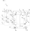
- the energy conversion module 20 is located in a vicinity of the regenerative energy source 4 in order to reduce any losses of electricity generated at the regenerative energy source 4. As the electricity generation of the regenerative energy source 4 typically depends on external circumstance, e.g. weather conditions, or the tide, the energy conversion module 20 is designed to power-up or ramp up from a minimum operating capacity any time there is a surplus of electricity generated at the regenerative energy source 4.
- the energy conversion module 20 converts the electricity from the regenerative energy source 4 into gas.
- the gas may be methane, i.e. synthetic gas, or hydrogen or a mixture thereof.
- the energy conversion module 20 - in any case - comprises an electrolyzer 21 for transforming electricity from the regenerative source 4 to hydrogen. This is achieved by the additional intake of water from at least one water source 22.
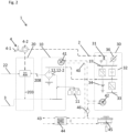
- the produced hydrogen 201 may be used for feeding the hydrogen via a hydrogen connection 203 into the gas network 3 (cf. Fig. 2 ) or to directly supply 202 the power source module 10 in case the power source module is close to the energy conversion module 20 (cf. Fig. 1 and 3 ).
- the latter may be achieved by a separate connection 202 to the power source module 10.
- the energy conversion module 20 is configured to produce hydrogen and/or (synthetic) methane in case of an excess or surplus of regeneratively produced electricity relative to grid 2 demand, demand management, curtailment of the regenerative energy source from the grid 2 or market price changes in favor of green gas or hydrogen production.
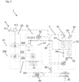
- the data center 30 comprises a connection 31 to the electricity grid 2.
- the data center 30 comprises a bi-directional converter or rectifier 32 that allows to convert AC electricity from the electricity grid 2 to DC electricity.
- a previous standby electricity source 36 e.g. a diesel generator
- a previous standby electricity source 36 e.g. a diesel generator
- FIGs. 1 to 3 a previous standby electricity source 36, e.g. a diesel generator, is shown (crossed out) to illustrate state of the art data center electricity supplies that are based on a connection to the electricity grid as the sole prime-rated electricity source and the diesel generator for fail-safe electricity supply.
- the data center 30 further comprises a data server 33 and/or data storage 33 that is connected to the data network (not shown) to serve the purpose of the data center 30.
- the data center 30 comprises an uninterruptible power source (UPS) 35 that comprises a battery assembly.
- UPS uninterruptible power source
- the UPS is configured to act as a fail-safe electricity source for the data center 30, in case both prime-rated electricity sources would fail at the same time.
- the UPS 35 may be charged with DC electricity from the bi-directional converter 32/ rectifier (cf. Fig. 1 ) or more directly by DC electricity provided by a DC power source module 10 (cf. Fig. 2 and 3 ).
- the data center system 1 may optionally comprise a heat recovery and distribution system 40 that is configured to export heat recovered from the data center 30, particularly from the data center server 33 comprised by the data center, and the power source module 10 to a heat exchanger 41, 42, arranged and adapted to export the recovered heat into a district heating system 43.
- a heat recovery and distribution system 40 that is configured to export heat recovered from the data center 30, particularly from the data center server 33 comprised by the data center, and the power source module 10 to a heat exchanger 41, 42, arranged and adapted to export the recovered heat into a district heating system 43.
- the heat exchanger 41 at the power source module 10 is particularly located at the gas-powered electricity generator 12.
- the heat recovery system 40 can be built comparably compact.
- the recovery system 40 may comprise an additional means for dissipating remaining heat or a reservoir of colder heat exchange liquid 45.
- This optional heat recovery system 40 allows for using dissipated heat from the data center 30 and the power source module 10 for district heating rather than solely dissipating the heat to the surrounding.
- the system 1 according to the invention can be driven in a zero-carbon emission mode, such that during operation the net carbon dioxide production is zero or below zero.
- the energy conversion module 20 comprises the electrolyzer 21 configured to transform electricity from the regenerative energy source 4 to hydrogen.
- the energy conversion module 20 comprises a methanation plant 23 that is connected to the electrolyzer 21 to receive the generated hydrogen 201.
- the methanation plant 23 using carbon dioxide and/or carbon monoxide transforms the hydrogen into methane, i.e. synthetic gas.
- the carbon dioxide and/or carbon monoxide may be obtained from a direct capture facility (not shown) to which the energy conversion module 20 and in particular the methanation plant 23 comprised therein is connected 204.
- the methane is provided to the gas network 2 by means of a methane connection 205.
- the energy conversion module 20 may also be connected to a biogas facility (not shown) and configured to feed the biogas into the gas network 2.
- the embodiment shown in Fig. 1 allows the provision of methane to the gas network 2 and simultaneously or alternatively the provision of hydrogen to the power source module 10 by means of the separate connection 202.
- the separate connection 202 is an optional component, which may be realized in case a proximity of the energy conversion module 20 and power source module 10 is sufficiently close.
- Fig. 1 further illustrates a variant of the power source module 10 that comprises a reciprocating gas engine 12-1 as the gas-powered electricity generator 12.
- the reciprocating gas engine 12-1 is configured to burn gas from the gas network 3 and to produce AC electricity from this process.
- the reciprocating gas engine 12-1 is configured to burn methane, hydrogen or a mixture thereof.
- the reciprocating gas engine 12-1 may be configured to also combust said gases.
- the gas provided to the reciprocating gas engine 12-1 is methane or blended gas, i.e. methane with 0% to 25% hydrogen or even pure hydrogen.
- the local gas storage 11 in the embodiment depicted in Fig. 1 comprises methane.
- Blending of the gas may be facilitated at the power source module 10 by mixing the gas inputs of 202 and 206 at a mixer 207, or wherein the gas from the gas network 3 may already comprise a methane hydrogen mix.
- Using a reciprocating gas engine 12-1 as the electricity generating source of the power source module 10, allows for producing AC electricity that is then provided to the data center 10 via the same connection that may have been used before by the standby electricity source 36.
- the AC electricity is provided synchronous to the AC electricity provided by the electricity grid 2.
- the system 1 comprises appropriate means. Providing the electricity in synch with the electricity grid 2 allows for stabilizing the electricity grid via the data center 10.
- the electricity from the electricity grid 2 and the electricity from the power source module 10 share, i.e. are connected to a common conducting element 37 that enables grid stabilization with synched electricity sources at the data center 10.
- the common conducting element 37 is connected to the bidirectional converter 32 or rectifier 32 that transforms the AC electricity to DC electricity, which may be used to charge the UPS or that may be used for powering the data center's 10 components, such as the data server 33.
- the power source module 10 is configured to generate electricity in the range from 0.5MW to 2.5MW per module, which on the one hand ensures that the power source module 10 qualifies as a prime-rated electricity source and on the other hand allows for arranging the power source module 10 in the vicinity of an existing data center 30, particularly in urban areas, where space limits sizes of power source modules particularly in terms of space constraints, and further in terms of heat generating, noise and/or pollution limitations.
- the system 1 may be expanded and scaled by connecting more power source modules to more data centers.
- each data center 30 may be provided and equipped with its own power source module 10 or a plurality of modules (cf Fig. 5 ).
- Fig. 2 depicts an exemplary embodiment of the invention, wherein the energy conversion module 20 solely comprises the electrolyzer 21 and no methanation plant.
- the hydrogen produced by the electrolyzer 21 is fed into the gas network 3 via connection 203.
- the gas network 3 may be configured to transport blended gas, i.e. methane and hydrogen, or pure hydrogen.
- the power source module 10 may provide recovered water to the energy conversion module 20 via a separate connection 208.
- the gas network 3 is a hydrogen gas network 3.
- the power source module 10 in contrast to the embodiment shown in Fig. 1 , uses a fuel cell 12-2 as the gas-powered electricity generator 12.
- the fuel cell 12-2 is connected to the hydrogen gas network 3 and is provided either via said gas network 3 or the local gas storage 11, which is a hydrogen gas storage in the located outside of the power source module 10, with (pure) hydrogen.
- the fuel cell 12-2 may be a proton-exchange membrane fuel cell (PEMFC) - also known as polymer electrolyte membrane fuel cell. This kind of fuel cell is very compact and light weight, has low operating core temperatures of ⁇ 100°C and is able to rapidly accept load.
- PEMFC proton-exchange membrane fuel cell
- the connection with the data center 10 is down-stream the bidirectional converter 32 of the data center 30. This allows to directly charge the UPS 35, to power the data center 30 or to the convert the DC electricity to AC electricity via the bi-directional converter 32 such as to use the converted and synchronized AC electricity for grid stabilization via the common conducting element 37 upstream the bi-directional converter 32.
- this embodiment provides a robust and sustainable data center system 1 with very low noise, vibration, particle, and gas emissions. Furthermore, this embodiment allows for the adaption and direct use of a hydrogen gas network.
- Fig. 3 shows a variation, wherein in this example, the energy conversion module 20 comprises the methanation plant 23 and has in essence the same layout as the energy conversion module 20 as already detailed in Fig. 1 .
- the energy conversion module 20 in Fig. 3 is optionally connected to a methane reformer 13 comprised in the power source module 10.
- the connection 209 provides carbon dioxide generated in the process of reformation to the methanation plant 23.
- the reformer 13 allows to convert the methane for the gas network 3 to hydrogen that may then be used by the fuel cell 12-2 of the power source module 10.
- the energy conversion module 20 may provide pure hydrogen via the separate connection 202 to the power source module 10 in case the energy conversion module 20 and the power source module 10 are located close to each other.
- the power source module 10 further comprises a back-up battery assembly 14 for storing electricity, particularly for compensating sudden load changes on the power source module 10.
- the gas network 3 provides a mix of methane and hydrogen
- a membrane filter in combination with a PSA filter is used for extracting pure hydrogen from the gas mix provided by the gas network 3.
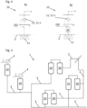
- Fig. 4A and B show a similar power source module 10 comprising the reciprocating gas engine 12-1.
- the reciprocating gas engine 12-1 is configured to run on methane and/or a mix of methane and hydrogen - and particularly even on LPG stored in the local gas storage 11.
- the reciprocating gas engine is configured to run on pure hydrogen.
- the power source module 10 comprises a filter assembly 15, with a membrane and/or a PSA filter, that extract the hydrogen from the gas mix, such that the reciprocating gas engine 12-1 is provided with pure hydrogen.
- the filter assembly 15 solely comprises the membrane filter, as the reciprocating gas engine may not require hydrogen of particular high purity.
- Fig. 5 the system 1 that comprises plurality of power source modules 10 and data centers 30 as well as two energy conversion modules 20.
- This example illustrates the scalability of the system 1 and the possibility to successively transform an existing conventionally powered data center infrastructure to the system 1 to incorporate the data centers in a carbon neutral data center system 1.
Landscapes
- Engineering & Computer Science (AREA)
- Power Engineering (AREA)
- Management, Administration, Business Operations System, And Electronic Commerce (AREA)
Claims (12)
- Datencentersystem (1), das zumindest die folgenden Komponenten umfasst: ein Datencenter (30), ein Energiequellenmodul (10), und ein Energiekonversionsmodul (20), wobei- das Datencenter (30) mit mindestens zwei Primärstromquellen verbunden ist, die dazu eingerichtet sind, Elektrizität für das Datencenter (30) bereitzustellen, wobei eine erste Stromquelle ein Stromnetz (2) ist und wobei eine zweite Stromquelle das Energiequellenmodul (10) ist, wobei- das Energiequellenmodul (10) einen gasbetriebenen Stromgenerator (12, 12-1, 12-2) zur Erzeugung von Strom aus Gas umfasst, wobei das Energiequellenmodul (10) mit einem Gasnetz (3) verbunden ist, wobei das Energiequellenmodul (10) ferner mit dem Datencenter (30) verbunden ist, wobei- das Energiekonversionsmodul (20) mit einer regenerativen Energiequelle (4), die konfiguriert ist, Elektrizität zu erzeugen, sowie mit dem Gasnetz (3) verbunden ist, wobei das Energiekonversionsmodul (20) konfiguriert ist, Gas, das Wasserstoff und/oder Methan umfasst oder daraus besteht, unter Verwendung von Elektrizität von der regenerativen Energiequelle (4) zu erzeugen, wobei das Energiekonversionsmodul (20) konfiguriert ist, das erzeugte Gas in das Gasnetz (3) einzuspeisen, wobeidas System (1) konfiguriert ist, um Elektrizität von dem Energiequellenmodul (10) an das Datencenter (30) bereitzustellen, um so eine Last auf dem Elektrizitätsnetz (2) zu reduzieren und so, dass das Datencenter (1) von den mindestens zwei Primärstromquellen gleichzeitig versorgt wird, wobei das System (1) konfiguriert ist, Elektrizität von dem Energiequellenmodul (10) über das Datencenter (30) synchron zu der von dem Elektrizitätsnetz (2) bereitgestellten Elektrizität bereitzustellen, wobei das Elektrizitätsnetz (2) mit einem gemeinsamen Leitelement (37) verbunden ist, das ferner mit einem bidirektionalen Konverter (32) oder einem Gleichrichter des Datencenters (10) verbunden ist, dadurch gekennzeichnet, dass das Energiequellenmodul (10) einen Kolbengasmotor (12-1) umfasst, der konfiguriert ist, um dem Energiequellenmodul (10) bereitgestelltes Gas zu verbrennen, um Wechselstrom zu erzeugen, wobei das Energiequellenmodul (10) mit dem gemeinsamen Leitelement (37) verbunden ist, das eine Netzstabilisierung mit den synchronisierten Stromquellen im Datencenter (10) ermöglicht.
- Datencentersystem (1), das zumindest die folgenden Komponenten umfasst: ein Datencenter (30), ein Energiequellenmodul (10) und ein Energiekonversionsmodul (20), wobei- das Datencenter (30) mit mindestens zwei Primärstromquellen verbunden ist, die dazu eingerichtet sind, Elektrizität für das Datencenter (30) bereitzustellen, wobei eine erste Elektrizitätsquelle ein Elektrizitätsnetz (2) ist und wobei eine zweite Elektrizitätsquelle das Energiequellenmodul (10) ist, wobei- das Energiequellenmodul (10) einen gasbetriebenen Stromgenerator (12, 12-1, 12-2) zur Erzeugung von Strom aus Gas umfasst, wobei das Energiequellenmodul (10) mit einem Gasnetz (3) verbunden ist, wobei das Energiequellenmodul (10) ferner mit dem Datencenter (30) verbunden ist, wobei- das Energiekonversionsmodul (20) mit einer regenerativen Energiequelle (4), die konfiguriert ist, Elektrizität zu erzeugen, sowie mit dem Gasnetz (3) verbunden ist, wobei das Energiekonversionsmodul (20) konfiguriert ist, Gas, das Wasserstoff und/oder Methan umfasst oder daraus besteht, unter Verwendung von Elektrizität von der regenerativen Energiequelle (4) zu erzeugen, wobei das Energiekonversionsmodul (20) konfiguriert ist, das erzeugte Gas in das Gasnetz (3) einzuspeisen, wobeidas System (1) konfiguriert ist, Elektrizität von dem Energiequellenmodul (10) an das Datencenter (30) bereitzustellen, um so eine Last auf dem Elektrizitätsnetz (2) zu reduzieren und so, dass das Datencenter (1) von den mindestens zwei Primärstromquellen gleichzeitig versorgt wird, wobei das System (1) konfiguriert ist, Elektrizität von dem Energiequellenmodul (10) über das Datencenter (30) synchron zu der von dem Elektrizitätsnetz (2) bereitgestellten Elektrizität bereitzustellen, wobei das Elektrizitätsnetz (2) mit einem gemeinsamen Leitelement (37) verbunden ist, das ferner mit einem bidirektionalen Konverter (32) verbunden ist, wobei das Energiequellenmodul (10) so konfiguriert ist, dass es Gleichstrom erzeugt, und eine Brennstoffzelle (12-2) umfasst, die so konfiguriert ist, dass sie Gas in Gleichstrom umwandelt, wobei das Energiequellenmodul dem bidirektionalen Wandler (32) nachgeschaltet ist, um das Datencenter (30) mit Strom zu versorgen oder den Gleichstrom über den bidirektionalen Wandler (32) in Wechselstrom umzuwandeln, um den umgewandelten und synchronisierten Wechselstrom über das gemeinsame Leitelement (37) stromaufwärts des bidirektionalen Wandlers (32) zur Netzstabilisierung zu verwenden, dadurch gekennzeichnet, dass das Datencenter (30) einen weiteren Wandler umfasst, der konfiguriert ist, um Gleichstrom, der von dem Energiequellenmodul stromabwärts des bidirektionalen Wandlers bereitgestellt wird, in Wechselstrom umzuwandeln, um einen Datencenter-Server (33) des Datencenters (30) zu versorgen.
- Das System (1) nach Anspruch 1 oder 2, wobei das System (1) so konfiguriert ist, dass es den Strom vom Energiequellenmodul (10) über das Datencenter (30) in das Stromnetz (2) einspeist, so dass eine stabilisierende Wirkung auf das Stromnetz (2) erzielt wird.
- Das System (1) nach einem der vorhergehenden Ansprüche, wobei das System (1) konfiguriert ist, um die Elektrizität von dem Energiequellenmodul (10) an das Datencenter (30) bereitzustellen, falls ein Energieäquivalent von erzeugtem Gas von dem Energiekonversionsmodul (20) gleich oder größer ist als ein Energieäquivalent von Gas, das erforderlich ist, um die Elektrizität durch das Energiequellenmodul (10) zu erzeugen, so dass das System (1) in der Lage ist, vollständig kohlenstoffneutral zu laufen, zumindest für den Fall, dass eine ausreichende Menge von Gas an dem Energiekonversionsmodul (20) erzeugt wird.
- Das System (1) nach einem der vorhergehenden Ansprüche, wobei das System (1) so konfiguriert ist, dass es das von dem Energiekonversionsmodul (20) unter Verwendung des Stroms aus der regenerativen Energiequelle erzeugte Gas zu unterschiedlichen Zeitpunkten und mit unterschiedlichen Raten der Gaserzeugung und/oder des Gasverbrauchs in Strom umwandelt.
- Das System (1) nach einem der vorhergehenden Ansprüche, wobei die Erzeugung von Gas am Energiekonversionsmodul (20) und die Umwandlung in Elektrizität am Energiequellenmodul (10) zu unterschiedlichen Zeiten während des Tages, des Monats oder des Jahres erfolgt.
- Das System (1) nach einem der vorhergehenden Ansprüche, wobei das Energiekonversionsmodul (20) eine Methanisierungsanlage (23) umfasst, die zur Umwandlung von Wasserstoff in Methan konfiguriert ist, das in das Gasnetz (3) eingespeist wird.
- Das System (1) nach einem der Ansprüche 2 oder 3 bis 7, wobei bei Bezugnahme auf Anspruch 2 das der Brennstoffzelle (12-2) bereitgestellte Gas Wasserstoff ist, insbesondere wobei die Brennstoffzelle (12-2) eine Protonenaustauschmembran-Brennstoffzelle ist, wobei der Wasserstoff- von dem Energiekonversionsmodul (20) erzeugt und direkt bereitgestellt wird,- durch einen am Energiequellenmodul (10) angeordneten lokalen Gasspeicher (11) bereitgestellt wird, wobei der lokale Gasspeicher (11) ein Wasserstoffgasspeicher ist,- durch einen Methanreformer (13) bereitgestellt wird, der das Energiequellenmodul (10) umfasst, wobei der Methanreformer (13) mit dem Gasnetz (3) verbunden und konfiguriert ist, Wasserstoff aus dem vom Gasnetz (3) bereitgestellten Methan zu erzeugen, und/oder- durch eine Filteranordnung (15) bereitgestellt wird, die einen Membranfilter und einen Druckwechseladsorptionsfilter umfasst, der mit dem Gasnetz (3) verbunden und konfiguriert ist, Wasserstoff aus einem Wasserstoff-Methan-Gasgemisch abzutrennen.
- Das System (1) nach einem der vorhergehenden Ansprüche, wobei das Datencenter (30) Komponenten umfasst, die eine Synchronisation des Stroms mit einer Frequenz und einer Phase des vom Stromnetz (2) bereitgestellten Stroms ermöglichen.
- Das System (1) nach einem der vorhergehenden Ansprüche, wobei das Energiequellenmodul (10) in einer ersten Einrichtung, wie einem ersten Container oder einer ersten Station vor Ort im Datencenter (30), umfasst ist, wobei das Energiekonversionsmodul (20) in einer zweiten Einrichtung, wie einem zweiten Container oder einer zweiten Station, umfasst ist.
- Das System (1) nach Anspruch 10, wobei das System (1) ein modulares System (1) ist, das eine Mehrzahl von Datencentern (30), eine Mehrzahl von ersten Einrichtungen (10) und eine oder mehrere zweite Einrichtungen (20) umfasst, die durch das Gasnetz (3) miteinander verbunden sind, und wobei jede erste Einrichtung (10) lokal angeordnet und mit einem der Datencenter (30) der Vielzahl von Datencentern (30) verbunden ist, wobei das Energiekonversionsmodul (20) in der Nähe der regenerativen Energiequelle angeordnet ist oder wobei das Energiekonversionsmodul (20) mit der regenerativen Energiequelle zusammen angeordnet ist.
- Das System (1) nach Anspruch 11, wobei jedes Datencenter (30) mit dem Elektrizitätsnetz (2) verbunden ist, wobei jedes dem Datencenter (30) zugeordnete Energiequellenmodul (10) konfiguriert ist, um Elektrizität für das Datencenter (30) und für das Elektrizitätsnetz (2) bereitzustellen, mit dem das Datencenter (30) verbunden ist, um die Elektrizität synchron für das Elektrizitätsnetz (2) bereitzustellen.
Priority Applications (7)
| Application Number | Priority Date | Filing Date | Title |
|---|---|---|---|
| PL22158675.3T PL4236002T3 (pl) | 2022-02-24 | 2022-02-24 | System centrum danych i sposób obsługi systemu centrum danych |
| EP22158675.3A EP4236002B1 (de) | 2022-02-24 | 2022-02-24 | Datenzentralensystem und verfahren zum betrieb des datenzentralensystems |
| ES22158675T ES3014989T3 (en) | 2022-02-24 | 2022-02-24 | Data center system and method of operating the data center system |
| US18/173,189 US12438380B2 (en) | 2022-02-24 | 2023-02-23 | Data center system and method of operating the data center system |
| EP23158529.0A EP4236003B1 (de) | 2022-02-24 | 2023-02-24 | Datencentersystem und verfahren zum betrieb des datencentersystems |
| ES23158529T ES2995888T3 (en) | 2022-02-24 | 2023-02-24 | Data center system and method of operating the data center system |
| PL23158529.0T PL4236003T3 (pl) | 2022-02-24 | 2023-02-24 | System centrum danych i sposób obsługi systemu centrum danych |
Applications Claiming Priority (1)
| Application Number | Priority Date | Filing Date | Title |
|---|---|---|---|
| EP22158675.3A EP4236002B1 (de) | 2022-02-24 | 2022-02-24 | Datenzentralensystem und verfahren zum betrieb des datenzentralensystems |
Publications (3)
| Publication Number | Publication Date |
|---|---|
| EP4236002A1 EP4236002A1 (de) | 2023-08-30 |
| EP4236002B1 true EP4236002B1 (de) | 2025-01-29 |
| EP4236002C0 EP4236002C0 (de) | 2025-01-29 |
Family
ID=80461711
Family Applications (1)
| Application Number | Title | Priority Date | Filing Date |
|---|---|---|---|
| EP22158675.3A Active EP4236002B1 (de) | 2022-02-24 | 2022-02-24 | Datenzentralensystem und verfahren zum betrieb des datenzentralensystems |
Country Status (4)
| Country | Link |
|---|---|
| US (1) | US12438380B2 (de) |
| EP (1) | EP4236002B1 (de) |
| ES (1) | ES3014989T3 (de) |
| PL (1) | PL4236002T3 (de) |
Citations (1)
| Publication number | Priority date | Publication date | Assignee | Title |
|---|---|---|---|---|
| WO2007018830A2 (en) * | 2005-07-23 | 2007-02-15 | Parmley Daniel W | Renewable energy power systems |
Family Cites Families (19)
| Publication number | Priority date | Publication date | Assignee | Title |
|---|---|---|---|---|
| CA2352626A1 (fr) * | 2001-07-12 | 2003-01-12 | Co2 Solution Inc. | Couplage d'une pile a hydrogene a un bioreacteur enzymatique de transformation et sequestration du co2 |
| DE10307112A1 (de) * | 2002-02-19 | 2003-10-30 | Proton Energy Sys Inc | System zur Speicherung und Rückgewinnung von Energie und Verfahren für dessen Gebrauch |
| US7000395B2 (en) * | 2004-03-11 | 2006-02-21 | Yuan Ze University | Hybrid clean-energy power-supply framework |
| US20080217998A1 (en) * | 2005-02-26 | 2008-09-11 | Parmley Daniel W | Renewable energy power systems |
| US8866334B2 (en) * | 2010-03-02 | 2014-10-21 | Icr Turbine Engine Corporation | Dispatchable power from a renewable energy facility |
| DE102012203334A1 (de) * | 2012-03-02 | 2013-09-05 | Wobben Properties Gmbh | Verfahren zum Betreiben eines Kombikraftwerks bzw. Kombikraftwerk |
| MX2015012914A (es) * | 2013-03-13 | 2016-04-04 | Bunker Energy Partners Llc | Sistemas y metodos para generar energia utilizando un ciclo de hidrogeno. |
| CN104242442A (zh) * | 2014-08-26 | 2014-12-24 | 浙江大学 | 一种双能源不间断电源装置及其方法 |
| US9559521B1 (en) * | 2015-12-09 | 2017-01-31 | King Electric Vehicles Inc. | Renewable energy system with integrated home power |
| US20190036345A1 (en) | 2017-07-25 | 2019-01-31 | Technische Werke Ludwigshafen Ag | Method and arrangement for providing electrical balancing power for stabilizing an alternating-current grid |
| EP3457513A1 (de) | 2017-09-13 | 2019-03-20 | Johnson Controls Technology Company | Gebäude-energiesystem mit lastverteilung |
| JP7178599B2 (ja) * | 2018-06-13 | 2022-11-28 | パナソニックIpマネジメント株式会社 | 電力供給システム及びその制御方法 |
| EP3811484A4 (de) * | 2018-06-20 | 2022-03-02 | Aquahydrex, Inc. | Mehrstufiges gleichstromverteilungssystem |
| US12481301B2 (en) * | 2020-01-06 | 2025-11-25 | Vybe Energy, Llc | Energy data presentation and visualization dashboard system, method and computer program product providing energy performance, diagnostic data and economic impact of all monitored energy consuming and production assets |
| US12009669B2 (en) * | 2020-03-25 | 2024-06-11 | Tdk Corporation | Power feeding system and power management device |
| JP6933745B1 (ja) * | 2020-03-27 | 2021-09-08 | 三菱パワー株式会社 | バイオガス利用メタネーションシステム |
| US11949279B2 (en) * | 2020-04-28 | 2024-04-02 | Daniel R. Cohn | Dispatchable flexible electricity generation for reliable decarbonized grids using multiplexed low-cost engines |
| JP7530319B2 (ja) * | 2021-03-17 | 2024-08-07 | 株式会社東芝 | 情報処理装置、情報処理方法、コンピュータプログラム及び情報処理システム |
| US11846393B2 (en) * | 2021-06-11 | 2023-12-19 | BWR Innovations LLC | Distributed hydrogen energy system and method |
-
2022
- 2022-02-24 PL PL22158675.3T patent/PL4236002T3/pl unknown
- 2022-02-24 EP EP22158675.3A patent/EP4236002B1/de active Active
- 2022-02-24 ES ES22158675T patent/ES3014989T3/es active Active
-
2023
- 2023-02-23 US US18/173,189 patent/US12438380B2/en active Active
Patent Citations (1)
| Publication number | Priority date | Publication date | Assignee | Title |
|---|---|---|---|---|
| WO2007018830A2 (en) * | 2005-07-23 | 2007-02-15 | Parmley Daniel W | Renewable energy power systems |
Also Published As
| Publication number | Publication date |
|---|---|
| US12438380B2 (en) | 2025-10-07 |
| EP4236002A1 (de) | 2023-08-30 |
| EP4236002C0 (de) | 2025-01-29 |
| ES3014989T3 (en) | 2025-04-28 |
| US20230268743A1 (en) | 2023-08-24 |
| PL4236002T3 (pl) | 2025-09-29 |
Similar Documents
| Publication | Publication Date | Title |
|---|---|---|
| Rispoli et al. | Constrained optimal design of a reversible solid oxide cell-based multiple load renewable microgrid | |
| El-Khattam et al. | Distributed generation technologies, definitions and benefits | |
| Adefarati et al. | Energizing renewable energy systems and distribution generation | |
| Ibrahim et al. | Techno-economic analysis of different energy storage technologies | |
| US6787258B2 (en) | Hydrogen based energy storage apparatus and method | |
| Xie et al. | Economic analysis of hydrogen-powered data center | |
| US9871381B2 (en) | Regenerative power supply system and method | |
| US20110094242A1 (en) | Method and Apparatus for Generating Sustainable, Study State Power and Cooling from a Intermittent Power Source using Renewable Energy as a Primary Power Source | |
| KR20130066100A (ko) | 전력 소비 제어 장치 및 방법 | |
| Stoppato et al. | The importance of energy storage | |
| Brancaleoni et al. | Hybrid solar and hydrogen energy system 0-D model for off-grid sustainable power system: A case in Italy | |
| Forsberg | Economics of meeting peak electricity demand using hydrogen and oxygen from base-load nuclear or off-peak electricity | |
| EP4236002B1 (de) | Datenzentralensystem und verfahren zum betrieb des datenzentralensystems | |
| EP4236003B1 (de) | Datencentersystem und verfahren zum betrieb des datencentersystems | |
| Gospodinova et al. | Techno-economic feasibility analysis of nearly-zero hybrid energy system for the city of Sofia in Bulgaria | |
| WO2022147523A1 (en) | Supplying off-grid power to a remote facility | |
| Petrie et al. | Distributed generation in developing countries | |
| Strachan | Distributed energy, overview | |
| Kronkalns et al. | Hydrogen as a Pathway to Heat Production | |
| UA143548U (uk) | Спосіб балансування енергетичної системи із використанням водню | |
| Sauer | The demand for energy storage in regenerative energy systems | |
| Namrata et al. | Microgrid Design Evolution and Architecture | |
| de Anda et al. | Conceptual study on the energy independence of fuel cell cogeneration systems using solar energy | |
| WO2025133594A1 (en) | Low carbon energy system | |
| Tajwar et al. | Use of bidirectional DC-DC buck boost converter in distributed energy resources (DER) |
Legal Events
| Date | Code | Title | Description |
|---|---|---|---|
| STAA | Information on the status of an ep patent application or granted ep patent |
Free format text: STATUS: EXAMINATION IS IN PROGRESS |
|
| PUAI | Public reference made under article 153(3) epc to a published international application that has entered the european phase |
Free format text: ORIGINAL CODE: 0009012 |
|
| 17P | Request for examination filed |
Effective date: 20220928 |
|
| AK | Designated contracting states |
Kind code of ref document: A1 Designated state(s): AL AT BE BG CH CY CZ DE DK EE ES FI FR GB GR HR HU IE IS IT LI LT LU LV MC MK MT NL NO PL PT RO RS SE SI SK SM TR |
|
| RAP3 | Party data changed (applicant data changed or rights of an application transferred) |
Owner name: NLIGHTEN HQ B.V. |
|
| REG | Reference to a national code |
Ref country code: DE Free format text: PREVIOUS MAIN CLASS: H02J0003380000 Ipc: H02J0003280000 Ref country code: DE Ref legal event code: R079 Ref document number: 602022009908 Country of ref document: DE Free format text: PREVIOUS MAIN CLASS: H02J0003380000 Ipc: H02J0003280000 |
|
| RIC1 | Information provided on ipc code assigned before grant |
Ipc: H02J 3/38 20060101ALI20241002BHEP Ipc: H02J 3/28 20060101AFI20241002BHEP |
|
| GRAP | Despatch of communication of intention to grant a patent |
Free format text: ORIGINAL CODE: EPIDOSNIGR1 |
|
| STAA | Information on the status of an ep patent application or granted ep patent |
Free format text: STATUS: GRANT OF PATENT IS INTENDED |
|
| GRAS | Grant fee paid |
Free format text: ORIGINAL CODE: EPIDOSNIGR3 |
|
| INTG | Intention to grant announced |
Effective date: 20241113 |
|
| GRAA | (expected) grant |
Free format text: ORIGINAL CODE: 0009210 |
|
| STAA | Information on the status of an ep patent application or granted ep patent |
Free format text: STATUS: THE PATENT HAS BEEN GRANTED |
|
| AK | Designated contracting states |
Kind code of ref document: B1 Designated state(s): AL AT BE BG CH CY CZ DE DK EE ES FI FR GB GR HR HU IE IS IT LI LT LU LV MC MK MT NL NO PL PT RO RS SE SI SK SM TR |
|
| REG | Reference to a national code |
Ref country code: GB Ref legal event code: FG4D |
|
| REG | Reference to a national code |
Ref country code: CH Ref legal event code: EP |
|
| REG | Reference to a national code |
Ref country code: DE Ref legal event code: R096 Ref document number: 602022009908 Country of ref document: DE |
|
| REG | Reference to a national code |
Ref country code: IE Ref legal event code: FG4D |
|
| U01 | Request for unitary effect filed |
Effective date: 20250218 |
|
| U07 | Unitary effect registered |
Designated state(s): AT BE BG DE DK EE FI FR IT LT LU LV MT NL PT RO SE SI Effective date: 20250224 |
|
| PGFP | Annual fee paid to national office [announced via postgrant information from national office to epo] |
Ref country code: IE Payment date: 20250321 Year of fee payment: 4 |
|
| U20 | Renewal fee for the european patent with unitary effect paid |
Year of fee payment: 4 Effective date: 20250411 |
|
| PG25 | Lapsed in a contracting state [announced via postgrant information from national office to epo] |
Ref country code: RS Free format text: LAPSE BECAUSE OF FAILURE TO SUBMIT A TRANSLATION OF THE DESCRIPTION OR TO PAY THE FEE WITHIN THE PRESCRIBED TIME-LIMIT Effective date: 20250429 |
|
| PGFP | Annual fee paid to national office [announced via postgrant information from national office to epo] |
Ref country code: ES Payment date: 20250407 Year of fee payment: 4 |
|
| PG25 | Lapsed in a contracting state [announced via postgrant information from national office to epo] |
Ref country code: NO Free format text: LAPSE BECAUSE OF FAILURE TO SUBMIT A TRANSLATION OF THE DESCRIPTION OR TO PAY THE FEE WITHIN THE PRESCRIBED TIME-LIMIT Effective date: 20250429 Ref country code: IS Free format text: LAPSE BECAUSE OF FAILURE TO SUBMIT A TRANSLATION OF THE DESCRIPTION OR TO PAY THE FEE WITHIN THE PRESCRIBED TIME-LIMIT Effective date: 20250529 |
|
| PG25 | Lapsed in a contracting state [announced via postgrant information from national office to epo] |
Ref country code: HR Free format text: LAPSE BECAUSE OF FAILURE TO SUBMIT A TRANSLATION OF THE DESCRIPTION OR TO PAY THE FEE WITHIN THE PRESCRIBED TIME-LIMIT Effective date: 20250129 |
|
| PG25 | Lapsed in a contracting state [announced via postgrant information from national office to epo] |
Ref country code: GR Free format text: LAPSE BECAUSE OF FAILURE TO SUBMIT A TRANSLATION OF THE DESCRIPTION OR TO PAY THE FEE WITHIN THE PRESCRIBED TIME-LIMIT Effective date: 20250430 |
|
| PGFP | Annual fee paid to national office [announced via postgrant information from national office to epo] |
Ref country code: CH Payment date: 20250407 Year of fee payment: 4 |
|
| PG25 | Lapsed in a contracting state [announced via postgrant information from national office to epo] |
Ref country code: SM Free format text: LAPSE BECAUSE OF FAILURE TO SUBMIT A TRANSLATION OF THE DESCRIPTION OR TO PAY THE FEE WITHIN THE PRESCRIBED TIME-LIMIT Effective date: 20250129 |
|
| PG25 | Lapsed in a contracting state [announced via postgrant information from national office to epo] |
Ref country code: MC Free format text: LAPSE BECAUSE OF FAILURE TO SUBMIT A TRANSLATION OF THE DESCRIPTION OR TO PAY THE FEE WITHIN THE PRESCRIBED TIME-LIMIT Effective date: 20250129 |
|
| PGFP | Annual fee paid to national office [announced via postgrant information from national office to epo] |
Ref country code: PL Payment date: 20250317 Year of fee payment: 4 |
|
| PG25 | Lapsed in a contracting state [announced via postgrant information from national office to epo] |
Ref country code: CZ Free format text: LAPSE BECAUSE OF FAILURE TO SUBMIT A TRANSLATION OF THE DESCRIPTION OR TO PAY THE FEE WITHIN THE PRESCRIBED TIME-LIMIT Effective date: 20250129 |
|
| PG25 | Lapsed in a contracting state [announced via postgrant information from national office to epo] |
Ref country code: SK Free format text: LAPSE BECAUSE OF FAILURE TO SUBMIT A TRANSLATION OF THE DESCRIPTION OR TO PAY THE FEE WITHIN THE PRESCRIBED TIME-LIMIT Effective date: 20250129 |
|
| PLBE | No opposition filed within time limit |
Free format text: ORIGINAL CODE: 0009261 |
|
| STAA | Information on the status of an ep patent application or granted ep patent |
Free format text: STATUS: NO OPPOSITION FILED WITHIN TIME LIMIT |
|
| 26N | No opposition filed |
Effective date: 20251030 |