EP4235910A1 - Battery module - Google Patents
Battery module Download PDFInfo
- Publication number
- EP4235910A1 EP4235910A1 EP22215995.6A EP22215995A EP4235910A1 EP 4235910 A1 EP4235910 A1 EP 4235910A1 EP 22215995 A EP22215995 A EP 22215995A EP 4235910 A1 EP4235910 A1 EP 4235910A1
- Authority
- EP
- European Patent Office
- Prior art keywords
- bus bar
- bar housing
- battery module
- assembly
- battery
- Prior art date
- Legal status (The legal status is an assumption and is not a legal conclusion. Google has not performed a legal analysis and makes no representation as to the accuracy of the status listed.)
- Granted
Links
Images








Classifications
-
- H—ELECTRICITY
- H01—ELECTRIC ELEMENTS
- H01M—PROCESSES OR MEANS, e.g. BATTERIES, FOR THE DIRECT CONVERSION OF CHEMICAL ENERGY INTO ELECTRICAL ENERGY
- H01M10/00—Secondary cells; Manufacture thereof
- H01M10/42—Methods or arrangements for servicing or maintenance of secondary cells or secondary half-cells
- H01M10/48—Accumulators combined with arrangements for measuring, testing or indicating the condition of cells, e.g. the level or density of the electrolyte
- H01M10/482—Accumulators combined with arrangements for measuring, testing or indicating the condition of cells, e.g. the level or density of the electrolyte for several batteries or cells simultaneously or sequentially
-
- H—ELECTRICITY
- H01—ELECTRIC ELEMENTS
- H01M—PROCESSES OR MEANS, e.g. BATTERIES, FOR THE DIRECT CONVERSION OF CHEMICAL ENERGY INTO ELECTRICAL ENERGY
- H01M50/00—Constructional details or processes of manufacture of the non-active parts of electrochemical cells other than fuel cells, e.g. hybrid cells
- H01M50/50—Current conducting connections for cells or batteries
- H01M50/502—Interconnectors for connecting terminals of adjacent batteries; Interconnectors for connecting cells outside a battery casing
- H01M50/505—Interconnectors for connecting terminals of adjacent batteries; Interconnectors for connecting cells outside a battery casing comprising a single busbar
-
- H—ELECTRICITY
- H01—ELECTRIC ELEMENTS
- H01M—PROCESSES OR MEANS, e.g. BATTERIES, FOR THE DIRECT CONVERSION OF CHEMICAL ENERGY INTO ELECTRICAL ENERGY
- H01M10/00—Secondary cells; Manufacture thereof
- H01M10/42—Methods or arrangements for servicing or maintenance of secondary cells or secondary half-cells
- H01M10/48—Accumulators combined with arrangements for measuring, testing or indicating the condition of cells, e.g. the level or density of the electrolyte
-
- H—ELECTRICITY
- H01—ELECTRIC ELEMENTS
- H01M—PROCESSES OR MEANS, e.g. BATTERIES, FOR THE DIRECT CONVERSION OF CHEMICAL ENERGY INTO ELECTRICAL ENERGY
- H01M10/00—Secondary cells; Manufacture thereof
- H01M10/42—Methods or arrangements for servicing or maintenance of secondary cells or secondary half-cells
- H01M10/48—Accumulators combined with arrangements for measuring, testing or indicating the condition of cells, e.g. the level or density of the electrolyte
- H01M10/486—Accumulators combined with arrangements for measuring, testing or indicating the condition of cells, e.g. the level or density of the electrolyte for measuring temperature
-
- H—ELECTRICITY
- H01—ELECTRIC ELEMENTS
- H01M—PROCESSES OR MEANS, e.g. BATTERIES, FOR THE DIRECT CONVERSION OF CHEMICAL ENERGY INTO ELECTRICAL ENERGY
- H01M10/00—Secondary cells; Manufacture thereof
- H01M10/60—Heating or cooling; Temperature control
- H01M10/65—Means for temperature control structurally associated with the cells
- H01M10/655—Solid structures for heat exchange or heat conduction
- H01M10/6556—Solid parts with flow channel passages or pipes for heat exchange
-
- H—ELECTRICITY
- H01—ELECTRIC ELEMENTS
- H01M—PROCESSES OR MEANS, e.g. BATTERIES, FOR THE DIRECT CONVERSION OF CHEMICAL ENERGY INTO ELECTRICAL ENERGY
- H01M50/00—Constructional details or processes of manufacture of the non-active parts of electrochemical cells other than fuel cells, e.g. hybrid cells
- H01M50/20—Mountings; Secondary casings or frames; Racks, modules or packs; Suspension devices; Shock absorbers; Transport or carrying devices; Holders
- H01M50/204—Racks, modules or packs for multiple batteries or multiple cells
- H01M50/207—Racks, modules or packs for multiple batteries or multiple cells characterised by their shape
- H01M50/209—Racks, modules or packs for multiple batteries or multiple cells characterised by their shape adapted for prismatic or rectangular cells
-
- H—ELECTRICITY
- H01—ELECTRIC ELEMENTS
- H01M—PROCESSES OR MEANS, e.g. BATTERIES, FOR THE DIRECT CONVERSION OF CHEMICAL ENERGY INTO ELECTRICAL ENERGY
- H01M50/00—Constructional details or processes of manufacture of the non-active parts of electrochemical cells other than fuel cells, e.g. hybrid cells
- H01M50/20—Mountings; Secondary casings or frames; Racks, modules or packs; Suspension devices; Shock absorbers; Transport or carrying devices; Holders
- H01M50/262—Mountings; Secondary casings or frames; Racks, modules or packs; Suspension devices; Shock absorbers; Transport or carrying devices; Holders with fastening means, e.g. locks
- H01M50/264—Mountings; Secondary casings or frames; Racks, modules or packs; Suspension devices; Shock absorbers; Transport or carrying devices; Holders with fastening means, e.g. locks for cells or batteries, e.g. straps, tie rods or peripheral frames
-
- H—ELECTRICITY
- H01—ELECTRIC ELEMENTS
- H01M—PROCESSES OR MEANS, e.g. BATTERIES, FOR THE DIRECT CONVERSION OF CHEMICAL ENERGY INTO ELECTRICAL ENERGY
- H01M50/00—Constructional details or processes of manufacture of the non-active parts of electrochemical cells other than fuel cells, e.g. hybrid cells
- H01M50/20—Mountings; Secondary casings or frames; Racks, modules or packs; Suspension devices; Shock absorbers; Transport or carrying devices; Holders
- H01M50/284—Mountings; Secondary casings or frames; Racks, modules or packs; Suspension devices; Shock absorbers; Transport or carrying devices; Holders with incorporated circuit boards, e.g. printed circuit boards [PCB]
- H01M50/287—Fixing of circuit boards to lids or covers
-
- H—ELECTRICITY
- H01—ELECTRIC ELEMENTS
- H01M—PROCESSES OR MEANS, e.g. BATTERIES, FOR THE DIRECT CONVERSION OF CHEMICAL ENERGY INTO ELECTRICAL ENERGY
- H01M50/00—Constructional details or processes of manufacture of the non-active parts of electrochemical cells other than fuel cells, e.g. hybrid cells
- H01M50/30—Arrangements for facilitating escape of gases
-
- H—ELECTRICITY
- H01—ELECTRIC ELEMENTS
- H01M—PROCESSES OR MEANS, e.g. BATTERIES, FOR THE DIRECT CONVERSION OF CHEMICAL ENERGY INTO ELECTRICAL ENERGY
- H01M50/00—Constructional details or processes of manufacture of the non-active parts of electrochemical cells other than fuel cells, e.g. hybrid cells
- H01M50/30—Arrangements for facilitating escape of gases
- H01M50/35—Gas exhaust passages comprising elongated, tortuous or labyrinth-shaped exhaust passages
- H01M50/367—Internal gas exhaust passages forming part of the battery cover or case; Double cover vent systems
-
- H—ELECTRICITY
- H01—ELECTRIC ELEMENTS
- H01M—PROCESSES OR MEANS, e.g. BATTERIES, FOR THE DIRECT CONVERSION OF CHEMICAL ENERGY INTO ELECTRICAL ENERGY
- H01M50/00—Constructional details or processes of manufacture of the non-active parts of electrochemical cells other than fuel cells, e.g. hybrid cells
- H01M50/50—Current conducting connections for cells or batteries
- H01M50/502—Interconnectors for connecting terminals of adjacent batteries; Interconnectors for connecting cells outside a battery casing
- H01M50/507—Interconnectors for connecting terminals of adjacent batteries; Interconnectors for connecting cells outside a battery casing comprising an arrangement of two or more busbars within a container structure, e.g. busbar modules
-
- H—ELECTRICITY
- H01—ELECTRIC ELEMENTS
- H01M—PROCESSES OR MEANS, e.g. BATTERIES, FOR THE DIRECT CONVERSION OF CHEMICAL ENERGY INTO ELECTRICAL ENERGY
- H01M50/00—Constructional details or processes of manufacture of the non-active parts of electrochemical cells other than fuel cells, e.g. hybrid cells
- H01M50/50—Current conducting connections for cells or batteries
- H01M50/502—Interconnectors for connecting terminals of adjacent batteries; Interconnectors for connecting cells outside a battery casing
- H01M50/519—Interconnectors for connecting terminals of adjacent batteries; Interconnectors for connecting cells outside a battery casing comprising printed circuit boards [PCB]
-
- H—ELECTRICITY
- H01—ELECTRIC ELEMENTS
- H01M—PROCESSES OR MEANS, e.g. BATTERIES, FOR THE DIRECT CONVERSION OF CHEMICAL ENERGY INTO ELECTRICAL ENERGY
- H01M10/00—Secondary cells; Manufacture thereof
- H01M10/60—Heating or cooling; Temperature control
- H01M10/61—Types of temperature control
- H01M10/613—Cooling or keeping cold
-
- H—ELECTRICITY
- H01—ELECTRIC ELEMENTS
- H01M—PROCESSES OR MEANS, e.g. BATTERIES, FOR THE DIRECT CONVERSION OF CHEMICAL ENERGY INTO ELECTRICAL ENERGY
- H01M10/00—Secondary cells; Manufacture thereof
- H01M10/60—Heating or cooling; Temperature control
- H01M10/62—Heating or cooling; Temperature control specially adapted for specific applications
- H01M10/625—Vehicles
-
- H—ELECTRICITY
- H01—ELECTRIC ELEMENTS
- H01M—PROCESSES OR MEANS, e.g. BATTERIES, FOR THE DIRECT CONVERSION OF CHEMICAL ENERGY INTO ELECTRICAL ENERGY
- H01M10/00—Secondary cells; Manufacture thereof
- H01M10/60—Heating or cooling; Temperature control
- H01M10/65—Means for temperature control structurally associated with the cells
- H01M10/656—Means for temperature control structurally associated with the cells characterised by the type of heat-exchange fluid
- H01M10/6561—Gases
-
- H—ELECTRICITY
- H01—ELECTRIC ELEMENTS
- H01M—PROCESSES OR MEANS, e.g. BATTERIES, FOR THE DIRECT CONVERSION OF CHEMICAL ENERGY INTO ELECTRICAL ENERGY
- H01M10/00—Secondary cells; Manufacture thereof
- H01M10/60—Heating or cooling; Temperature control
- H01M10/65—Means for temperature control structurally associated with the cells
- H01M10/656—Means for temperature control structurally associated with the cells characterised by the type of heat-exchange fluid
- H01M10/6567—Liquids
-
- H—ELECTRICITY
- H01—ELECTRIC ELEMENTS
- H01M—PROCESSES OR MEANS, e.g. BATTERIES, FOR THE DIRECT CONVERSION OF CHEMICAL ENERGY INTO ELECTRICAL ENERGY
- H01M2220/00—Batteries for particular applications
- H01M2220/20—Batteries in motive systems, e.g. vehicle, ship, plane
-
- Y—GENERAL TAGGING OF NEW TECHNOLOGICAL DEVELOPMENTS; GENERAL TAGGING OF CROSS-SECTIONAL TECHNOLOGIES SPANNING OVER SEVERAL SECTIONS OF THE IPC; TECHNICAL SUBJECTS COVERED BY FORMER USPC CROSS-REFERENCE ART COLLECTIONS [XRACs] AND DIGESTS
- Y02—TECHNOLOGIES OR APPLICATIONS FOR MITIGATION OR ADAPTATION AGAINST CLIMATE CHANGE
- Y02E—REDUCTION OF GREENHOUSE GAS [GHG] EMISSIONS, RELATED TO ENERGY GENERATION, TRANSMISSION OR DISTRIBUTION
- Y02E60/00—Enabling technologies; Technologies with a potential or indirect contribution to GHG emissions mitigation
- Y02E60/10—Energy storage using batteries
Definitions
- the present disclosure relates to a battery module.
- secondary batteries have been commonly used for not only portable devices but also electric vehicles (EVs) or hybrid electric vehicles (HEVs) driven by electrical driving sources or energy storage systems (ESSs).
- Types of the secondary batteries include lithium ion batteries, lithium polymer batteries, nickel cadmium batteries, nickel hydrogen batteries, and nickel zinc batteries.
- An operation voltage of a unit secondary battery cell, that is, a unit battery cell is often approximately 2.5 V to 4.6 V.
- the battery cells are connected in series to each other to constitute a battery pack. Furthermore, the battery cells are connected in parallel to each other to constitute a battery pack according to a charging/discharging capacity required for the battery pack. Accordingly, the number of the battery cells included in the battery pack may be variously set according to an output voltage or a charging/discharging capacity.
- a predetermined number of secondary battery cells may constitute one battery module and one or more battery modules and other components are assembled to constitute the battery pack.
- the secondary battery cells that constitute the battery module or the battery pack are general.
- Schemes for cooling a battery module may include two schemes of an air cooling scheme and a water cooling scheme.
- the air-cooling schemes are more widely used than water cooling schemes due to problems of a short circuit or waterproofing problems.
- the air cooling type battery module has low energy density per unit volume due to the unit cells for securing air passages and the intervals between the unit cells. Additionally, when an impact or vibration is applied to the battery module, the unit cells are adhered to each other, and may be blocked while foreign substances may be introduced into the narrow passage decreasing structure stability.
- a battery module including a battery assembly, in which multiple batteries are stacked, and a bus bar housing assembly that surrounds an upper side of the battery assembly.
- the bus bar housing assembly may include a temperature sensing part including a temperature sensor that has a first fixing hole and measures temperature, and a voltage sensing part including a pressure sensor that has a second fixing hole and measures pressure.
- the battery module also included a bus bar coupled to the temperature sensing part and the voltage sensing part, and a bus bar housing, coupled to the bus bar, surrounding an upper surface of the battery assembly, and extending downwards from opposite ends in leftward and rightward directions to surround a side surface of the battery assembly.
- the bus bar may include a bus bar body having a plate shape, a plurality of side end bending parts bent downwards from one end of the bus bar body in one of the leftward and rightward directions, and a connecting protrusion part, the temperature sensing part and the voltage sensing part being adhered to the connecting protrusion part, protruding inward from an opposite end of the bus bar body.
- the bus bar housing may include a bus bar housing body, the bus bar coupled thereto, surrounding an upper surface of the battery assembly.
- the bus bar housing may also include bending parts accommodating part disposed at opposite ends of the bus bar housing body in the leftward and rightward directions, and in which the plurality of side end bending part is accommodated, and a hook part protruding upwards while being bent from a central portion of the bus bar housing body toward an end thereof in one of the leftward and rightward directions, and adhered to an upper surface and a side surface of the bus bar body.
- the bus bar housing may further include a fixing boss protruding upwards from the bus bar housing body, which may be configured to be coupled to the first fixing hole of the temperature sensing part and the second fixing hole of the voltage sensing part, and a plurality of gas discharge holes provided in a central area in the one of the leftward and rightward directions on an upper side of the bus bar housing body to discharge a gas discharged from the battery assembly and formed in at least one of forward and rearward directions.
- the voltage sensing part and the bus bar housing may be joined to each other through laser welding.
- the bus bar housing may further include a partition wall protruding upwards from an end of the bus bar housing body.
- the battery module may further include a pair of side plate assemblies, located at opposite ends of the battery assembly in forward and rearward directions, which are configured to press the battery assembly, and a band member that surrounds the pair of side plate assemblies and the battery assembly to fasten the battery assembly and the side plate assemblies.
- the band member may include an upper band member configured to surround and fasten the battery assembly, the pair of side plate assemblies, and the bus bar housing assembly.
- the side plate assemblies may include an outer member including an outer member body extending in the leftward and rightward directions, and a bending area, in which opposite ends of the outer member body in the forward and rearward directions are bent inwards in the forward and rearward directions.
- the outer member may include a first protruding area protruding outwards in an upper area of the outer member body, and a second protruding area spaced apart from the first protruding area downwards and protruding outwards.
- the bus bar housing may further include a housing flange protruding outwards from side surfaces of the bus bar housing in the leftward and rightward directions.
- the upper band member may surround an area of the outer member, disposed between the first protruding area and the second protruding area, and an area of a side surface of the bus bar housing, disposed on an upper side of the housing flange.
- the upper band member may contact the housing flange.
- the battery module may further include an upper cover coupled to an upper side of the bus bar housing assembly.
- the bus bar housing assembly may include a bus bar housing formed on side surfaces of the bus bar housing body in the leftward and rightward directions and having a coupling recess having an inwardly recessed shape.
- the upper cover may include a cover body defining a body of the upper cover, and including an upper surface area and a side surface area extending downwards from an end of the upper surface area.
- the battery module may further include a cover hook formed on side surfaces of the cover body in the leftward and rightward directions, and protruding inwards in the leftward and rightward directions to be inserted into and coupled to the coupling recess.
- the temperature sensing part may be coupled to an upper side of the bus bar body, and the voltage sensing part may be coupled to a lower side of the bus bar body.
- a material of the band member may be a metal or a polymer resin.
- first, second, A, B, (a), (b) or the like may be used herein to describe components.
- Each of these terminologies is not used to define an essence, order or sequence of a corresponding component but used merely to distinguish the corresponding component from other component(s).
- a first component may be referred to as a second component, and similarly the second component may also be referred to as the first component.
- spatially relative terms such as “above,” “upper,” “below,” and “lower” may be used herein for ease of description to describe one element's relationship to another element as shown in the figures. Such spatially relative terms are intended to encompass different orientations of the device in use or operation in addition to the orientation depicted in the figures. For example, if the device in the figures is turned over, an element described as being “above” or “upper” relative to another element will then be “below” or “lower” relative to the other element. Thus, the term “above” encompasses both the above and below orientations depending on the spatial orientation of the device.
- the device may also be oriented in other ways (for example, rotated 90 degrees or at other orientations), and the spatially relative terms used herein are to be interpreted accordingly.
- FIG. 1 is a perspective view illustrating a battery module according to the present disclosure.
- FIG. 2 is an exploded perspective view of the battery module according to the present disclosure.
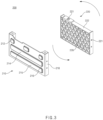
- FIG. 3 is a view illustrating a side plate assembly according to the present disclosure.
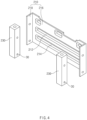
- FIG. 4 is a view illustrating an outer member and an outer bushing of the side plate member according to the present disclosure.
- FIG. 5 is a cross-sectional view of the side plate assembly according to the present disclosure.
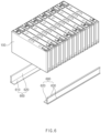
- FIG. 6 is a perspective view illustrating a coupling structure of the battery assembly and a lower guide bracket according to the present disclosure.
- FIG. 7 is a view illustrating a state, in which the lower guide bracket, the side plate assembly, and a band member are coupled to the battery assembly according to the present disclosure.
- FIG. 1 is a perspective view illustrating a battery module according to the present disclosure.
- FIG. 2 is an exploded perspective view of the battery module according to the present disclosure.
- FIG. 3 is a view illustrating a side plate assembly according
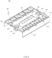
- FIG. 8 is a perspective view illustrating a bus bar housing assembly according to the present disclosure.
- FIG. 9 is an exploded perspective view illustrating the bus bar housing assembly according to the present disclosure.
- FIG. 10 is a partially enlarged detailed view of a coupling structure of a bus bar and a bus bar housing according to the present disclosure.
- FIGS. 11A to 11C are cross-sectional views illustrating portion A-A, portion B-B, and portion C-C of FIG. 10 .
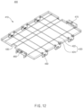
- FIG. 12 is a perspective view illustrating an upper cover according to the present disclosure.
- FIG. 13 is a view illustrating a state, in which a lower side of the battery module contacts a cooling passage according to the present disclosure.
- a battery module may include a battery assembly 100, a side plate assembly 300, a bus bar housing assembly 300, an upper cover 400, and a band member 500.
- a plurality of batteries may be stacked in the battery assembly 100.
- the battery assembly 100 of the present disclosure may be used for an electric vehicle, but the batter assembly 100 may be used with no limitation.
- the batteries provided in the battery assembly 100 may be angular batteries, but may be cylindrical batteries or pouch type batteries with no limitation.
- a pair of side plate assemblies 200 may be provided to be located at front and rear ends of the battery assembly 100.
- the side plate assemblies 200 may be adhered to the battery assembly 100 to press the battery assembly 100 in a forward/rearward direction. Accordingly, according to the present disclosure, the batteries provided in the battery assembly 100 may be restrained from being swollen
- the side plate assembly 200 may include an outer member 210, an inner member 220, and an outer bushing 230.
- the outer member 210 may include an outer member body 216 that extends in the leftward/rightward direction (for example, in leftward and rightward directions with respect to an axis (not shown) of the outer member, such as a sagittal axis), and a bending area 218, in which left and right ends of the outer member body 216 are bent inwards in the forward/rearward direction (for example, in forward and rearward directions with respect to the axis of the outer member).
- the outer member 210 may include a first protruding area 212, a second protruding area 214, and a third protruding area 216.
- the first protruding area 212 may be provided in an upper area of the outer member body 216, and may protrude outwards in the forward/rearward direction.
- the second protruding area 214 may be spaced apart downwards from the first protruding area 212 and may protrude outwards in the forward/rearward direction.
- the third protruding area 216 may be spaced apart downwards from the second protruding area 214 and may protrude outwards in the forward/rearward direction.
- a hole 30a may be formed in the bending area 218 of the outer member 210, a hole 30b may be formed in the outer bushing 230, and the outer member 210 and the outer bushing 230 may be welded and coupled to each other through the hole formed in the outer member 210 and the hole 30b formed in the outer bushing 230. Meanwhile, the outer member 210 may be manufactured through pressing, and may be manufactured of polymer resin-based plastic.
- the inner member 220 may be located on an inner side of the outer member 210 in the forward/rearward direction, and may be adhered to the battery assembly 100.
- the inner member 220 may include an inner member body 221, an insert nut 2220, an assembly boss 224, and an inner member reinforcing rib 226.
- the insert nut 222 may be electrically connected to the battery assembly 100, and may be inserted into the inner member body 221.
- a positive electrode 335 and a negative electrode 336 of the bus bar 330 may electrically connect the battery assembly 100 to a power demand site (for example, a motor) through an insert nut 222.
- the assembly boss 224 may be formed on left and right side surfaces of the inner member body 221 in correspondence to the assembly hole 232 to be coupled to the assembly hole 232 formed in the outer bushing 230.
- the inner member reinforcing rib 226 may be provided in an interior of the inner member body 221.
- the inner member reinforcing rib 226 may be formed in an interior of the inner member body 221 to have a honeycomb shape to protect the battery assembly 100 from an external impact or to absorb an impact to the battery assembly 100 due to a change in thicknesses of cells due to repeated charging and discharging of the battery.
- the shape of the inner member reinforcing rib 226 is not limited to the honeycomb shape.
- the outer bushing 230 may be provided at left and right ends of the inner member 220, and may be fixed to the bending area 218 of the outer member 210. It has been described above that the outer bushing 230 and the outer member 210 may be fixed to each other through welding in the hole 30a formed in the outer member 210 and the hole 30b formed in the outer bushing 230.
- the outer bushing 230 may include the assembly hole 232 such that the inner member 220 is inserted into an inner portion thereof.
- the bus bar housing assembly 300 may surround an upper side of the battery assembly 100.
- the bus bar housing assembly 300 may include a temperature sensing part 310, a voltage sensing part 320, the bus bar, a bus bar housing 340, and a connector 360.
- the temperature sensing part 310 may include a temperature sensor that measures temperature, and a first fixing hole 312 may be formed at a portion thereof.
- the temperature sensing part 310 may be a configuration for measuring temperatures of the battery assembly 100 and a periphery thereof. That is, it may be identified whether the batteries of the battery assembly 100 are abnormal through the batteries or the peripheral temperature detected through the temperature sensing part 310.
- the voltage sensing part 320 may include a pressure sensor that measures pressure, and a second fixing hole 322 may be formed at a portion thereof.
- a change in the volumes of the batteries in the battery assembly 100 may be detected through the voltage sensor of the voltage sensing part 320. That is, it may be detected in advance whether the batteries that constitute the battery assembly 100 are discharged or abnormal together with the above-described temperature sensing part 310, by detecting a deformation or a distortion degree of the battery assembly 100 according to a change in the volume of the battery assembly 100 through the voltage sensing part 320.
- the temperature sensing part 310 and the voltage sensing part 320 may include a printed circuit board (PCB).
- PCB printed circuit board
- the printed circuit board provided in the temperature sensing part 310 and the voltage sensing part 320 may be a flexible printed circuit board (FPCB).
- the voltage sensing part 320 and the bus bar housing 340 may be joined to each other through laser welding.
- energy density is high, a metal of a high melting point may be welded, welding heat input is very low, a range of directions of heat is narrow, and a heat source is a beam of light, and thus welding may be made in any environment through a transparent material.
- the welding scheme is not limited to the laser welding.
- the bus bar 330 may be coupled to the temperature sensing part 310 and the voltage sensing part 320.
- the bus bar 330 may include a bus bar body 331, a side end bending part 332, and a connecting protrusion part 334.
- the temperature sensing part 310 may be coupled to an upper side of the bus bar body 331, and the voltage sensing part 320 may be coupled to a lower side of the bus bar body 331.
- the voltage sensing part 320 may be coupled to the upper side of the bus bar body 331, and the temperature sensing part 310 may be coupled to the lower side of the bus bar body 331.
- the bus bar body 331 may have a plate shape.
- a plurality of side end bending parts 332 may have a shape that is bent downwards from left and right ends of the bus bar body 331.
- the bus bar 330 may be fixed to the bus bar housing 340 through the side end bending parts 332.
- the connecting protrusion part 334 may protrude inwards in the leftward/rightward direction from left and right ends of the bus bar body 331.
- the temperature sensing part 310 and the voltage sensing part 320 may be adhered to the connecting protrusion part 334. Accordingly, signals for the temperature and the pressure detected by the temperature sensing part 310 and the voltage sensing part 320 may be transmitted to the bus bar 330.
- the bus bar 330 may be coupled to the bus bar housing 340, and the bus bar housing 340 may extend downwards from the left and right ends while surrounding the upper surface of the battery assembly 100, and may surround a side surface of the battery assembly 100.
- the bus bar housing 340 may include a bus bar housing body 340-1, a bending part accommodating part 341, and a hook part 342.
- the bus bar 330 may be coupled to the bus bar housing body 340-1, and the bus bar housing body 340-1 may surround an upper surface of the battery assembly 100.
- the bending part accommodating part 341 may be formed at left and right ends of the bus bar housing body 340-1, and the side end bending part 332 may be accommodated therein. In more detail, a hole or a recess, into which the side end bending part 332 is inserted, may be formed in the bending part accommodating part 341.
- the hook part 342 may protrude upwards from a central portion of the bus bar housing body 340-1 toward left and right ends while being bent, and may be adhered to an upper surface and a side surface of the bus bar body 331. That is, the hook part 342 may be a configuration of fixing the bus bar body 331.
- the bus bar 330 may be coupled to the bus bar housing 340 while the side end bending part 332 formed in the bus bar body 331 may be stably accommodated in the bending part accommodating part 341 formed in the bus bar housing 340 at the corresponding shape and location. Furthermore, the upper surface of the bus bar body 331 may be adhered and supported through the hook part 342 formed at an upper portion of the bus bar housing 340 whereby separation of the bus bar 330 may be prevented and may be stably fixed to the bus bar housing 340.
- the bus bar housing 340 may further include a fixing boss 344, a gas discharge hole 345, a partition wall 347, and a housing flange 348.
- the fixing boss 344 may protrude upwards from the bus bar housing body 340-1 to be coupled to the temperature sensing part 310 and the first fixing hole 312 and the second fixing hole 322 of the voltage sensing part 320.
- a plurality of gas discharge holes 345 may be provided at a central area in the left and right direction on an upper side of the bus bar housing body 340-1 to discharge the gas discharged from the battery assembly 100, and may be formed along the forward/rearward direction.
- the gas discharge hole 345 may prevent discharging due to overheating of the battery assembly 100 by promptly discharging the heat emitted due to use of the battery assembly 100 to an outside whereby a lift span of the battery may be extended and ignition may be prevented.
- a plurality of gas discharge holes 345 may be provided along a direction, in which the batteries provided in the battery assembly 100 are stacked.
- the partition wall 347 may protrude upwards from the left and right ends of the bus bar housing body 340-1. Furthermore, the housing flange 348 may protrude outwards from the left and right side surfaces thereof.
- the partition wall 347 is a configuration for protecting the temperature sensing part 310, the voltage sensing part 320, and the bus bar 330 from an outside, and may protrude upwards from the left and right ends of the bus bar housing body 340-1 at a preset height.
- the bus bar housing 340 may include a coupling recess 346 that is formed on left and right side surfaces of the bus bar housing assembly 300 and has an inwardly recessed shape.
- the bus bar housing assembly 300 may be fixed to the upper cover 400 through coupling of the bus bar housing 340 including the coupling recess 345 that is formed on the left and right side surfaces of the bus bar housing assembly 300 and has the inwardly recessed shape and the upper cover 400 including the cover hook 450 that is formed on the left and right side surfaces of the cover body 410, which will be described below and protrudes inwards in the leftward/rightward direction to be inserted into and coupled to the coupling recess 345. Accordingly, because the bus bar housing assembly 300 may be protected from an outside, an unnecessary electrical connection between the battery assembly 100 and an external configuration may be prevented.
- the connector 360 may pass through a through-recess 430 and may be fixed to the bus bar housing 340.
- the connector 360 may be a configuration for delivering signal values measured by the temperature sensing part 310 and the voltage sensing part 320 to an outside.
- the upper cover 400 may be coupled to an upper side of the bus bar hosing assembly 300. As described above, the upper cover may be a configuration for protecting the bus bar housing assembly 300 from an outside.
- the upper cover 400 may include a cover body 410, a reinforcing rib 420, and a through recess 430.
- the cover body 410 may define a body of the upper cover 400, and may include an upper surface area and a side surface area that extends downwards from an end of the upper surface area.
- the cover body 410 may be coupled while the upper surface area of the cover body 410 surrounds an upper side of the bus bar housing assembly 300 and the side surface area thereof surrounds the side surface area of the bus bar housing assembly 300 including the partition wall 347 of the bus bar housing assembly 300.
- the reinforcing rib 420 may include a first reinforcing rib 422 that protrudes downwards from the upper surface area of the cover body 410 and extends in the forward/rearward direction, and a second reinforcing rib 424 that extend in a direction that crosses the forward/rearward direction.
- the reinforcing rib 420 may prevent deformation of the battery assembly 100 by reinforcing the battery assembly 100 in the forward/rearward direction and the crossing direction thereof through the first reinforcing rib 422 that is formed on an inner side of the cover 410 while crossing it to reinforce the cover body 410 in the forward/rearward direction, and the second reinforcing rib 424 that reinforces the cover body 410 in the direction that crosses the first reinforcing rib 422.
- the through recess 430 may be formed in the upper surface area of the cover body 410 and may have an upwardly recessed shape. As described above, the connector 360 may pass through the through recess 430 to be fixed to the bus bar housing 340 to various signals, such as a voltage and a temperature of the battery assembly 100, to an outside.
- the upper cover 400 may further include a cover hook 450, a positive engraved part 460, and a negative engraved part 470.
- the cover hook 450 may be formed on the left and right side surfaces of the cover body 410 and may protrude inwards in the leftward/rightward direction to be inserted into and coupled to the coupling recess 346 formed in the bus bar housing 340.
- the positive electrode engraved part 460 may be formed in an area that faces the positive terminal 335 of the bus bar housing assembly 300 and a plus (+) shape may be engraved.
- the negative electrode engraved part 470 may be formed in an area that faces the negative terminal 336 of the bus bar housing assembly 300 and a minus (-) shape may be engraved.
- the positive engraved part 460 and the negative engraved 470 which have described above, may be configurations for easily recognizing polarities of the terminals from an outside by the user.
- the battery module 10 may further include a lower guide bracket 600.
- a pair of lower guide bracket 600 may be coupled while lower ends of the battery assembly 100 in the leftward/rightward direction are seated on an inside thereof.
- the lower guide bracket 600 may include a first area 610, a second area 620, and a third area 630.
- the first area 610 may be adhered to a side surface of the battery assembly 100.
- the second area 620 may be bent from the first area 610 to be adhered to a lower surface of the battery assembly 100.
- the third area 630 may protrude from the upper and lower ends of the area 610 on an outside in the leftward/rightward direction.
- the band member 500 may be configured to surround the pair of side plate assemblies 200 and the battery assembly 100 to fasten the battery assembly 100 and the side plate assemblies 200.
- the band member 500 may include an upper band member 510 and a lower band member 520.
- the upper band member 510 may be configured to surround the battery assembly 100, the pair of side plate assemblies 200, and the bus bar housing assembly 300 to fasten the battery assembly 100, the pair of side plate assemblies 200, and the bus bar housing assembly 300.
- the upper band member 510 may be configured to surround an area of the outer member 210, which is formed between the first protruding area 212 and the second protruding area 214 and an area of a side surface of the bus bar housing 340, which is formed at an upper portion of the housing flange 348.
- the upper band member 510 may be configured to contact the housing flange 348.
- a material of the band member 500 may be a metal or a polymer resin.
- the band member 500 may be manufactured of a light metal, such as aluminum or an aluminum alloy, which has durability and elasticity, or a polymer resin that has durability and an excellent elasticity.
- the kinds of the polymer resin include a phenol resin, a polyurethane resin, a polyimide resin, an acryl resin, an urea/melanin resin, and a silicon resin.
- the lower band member 520 may be configured to surround the battery assembly 100, the pair of side plate assemblies 200, and the lower guide bracket 600 to fasten the battery assembly 100, the pair of side plate assemblies 200, and the lower guide bracket 600.
- the lower band member 520 may be configured to surround an area of the outer member 210, which is formed between the second protruding area 214 and the third protruding area 215, and an area of the first area 610 of the lower guide bracket 600, which is located between the pair of third areas 630.
- the configurations of the battery module 10 may be firmly fixed by fastening the side surface of the battery assembly 100 in upper and lower areas of the battery module 10 by using the upper band member 510 and the lower band member 520. Accordingly, the battery assembly 100 may be fastened while not using a separate subsidiary member, such as a case or a housing, in which a battery assembly 100 is accommodated whereby manufacturing performance is excellent and manufacturing time and costs may be reduced.
- a separate subsidiary member such as a case or a housing
- heat of the battery assembly 100 may be advantageously emitted whereby deformation or distortion of the battery due to heat may be prevented, and because a fire or an explosion due to emission of heat of the battery may be prevented, a life span of the battery may be extended by enhancing the durability of the battery as well.
- a lower area of the battery assembly 100 provided in the battery module 10 may directly contact a refrigerant that flows through the cooling passage 20, the heat emitted from the battery assembly may be cooled promptly and effectively.
- FIG. 14 is a view illustrating a first example, in which the band member is coupled, according to the present disclosure.
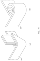
- FIG. 15 is a view illustrating a second example, in which a band member is coupled, according to the present disclosure.
- a hole may be formed at one end in a lengthwise direction, in which the band member 500 extends, and an opposite end thereof in the lengthwise direction may be inserted and coupled to the hole.
- an opposite end of the band member 500 may have a bent or rolled shape.
- the hole is formed at the end in the lengthwise direction, in which the band member 500 extends, and the opposite end thereof in the lengthwise direction is inserted into and coupled to the hole, and opposite ends of the band member 500 may be coupled to each other to be finished as the opposite end passes the hole at the one end and the opposite end is bent or rolled. Then, when the opposite end of the band member 500 is bent, it may be bent only once or two times or more to be coupled.
- opposite ends in a lengthwise direction, in which the band member 500 extends may be attached to each other and may have bent or rolled shapes.
- the opposite ends of the band member 600 in the lengthwise direction, in which the band member 600 extends are bent or rolled while being adhered to each other, and in this case, the adhered opposite ends may be finished while being bent or rolled to be coupled. Then, when the opposite end of the band member 500 is bent, it may be bent only once or two times or more to be coupled.
- a design may be standardized through enhancement of cooling performance and enhancement of a degree of freedom of disposition of a cooling layout by employing a scheme of directly cooling a lower end of the battery assembly.
- a weight, costs, and a volume of the battery assembly may be reduced and an energy density per weight may be enhanced by directly cooling the lower end of the battery assembly while not applying an additional heat exchange member such as a heat plate.
- the battery module may be standardized through securement of a degree of freedom of series or parallel stack of the batteries accommodated in the battery module and expansion of the shape of the battery assembly may be secured.
- the battery assembly may be stably fixed and the weight and costs of the battery assembly may be reduced while swelling is prevented, through application of the band member.
- schemes of some parts may be changed from extrusion of aluminum to pressing, or a light weight and an excellent insulation performance may be secured through application of plastic.
- An aspect of the present disclosure provides a battery module, in which a cooling performance may be enhanced and a degree of freedom of disposition of a cooling layout may be enhanced by directly cooling battery cells through a lower end of the battery module.
- Another aspect of the present disclosure provides a battery module, in which battery cells may be directly cooled while not adding a separate heat exchange device to cool heat generated in a battery.
Landscapes
- Chemical & Material Sciences (AREA)
- Chemical Kinetics & Catalysis (AREA)
- Electrochemistry (AREA)
- General Chemical & Material Sciences (AREA)
- Engineering & Computer Science (AREA)
- Manufacturing & Machinery (AREA)
- Connection Of Batteries Or Terminals (AREA)
- Battery Mounting, Suspending (AREA)
Abstract
Description
- This application claims the benefit of
Korean Patent Application Nos. 10-2022-0020944 10-2022-0020945 10-2022-0020946, all filed in the Korean Intellectual Property Office on February 17, 2022 - The present disclosure relates to a battery module.
- In recent years, secondary batteries have been commonly used for not only portable devices but also electric vehicles (EVs) or hybrid electric vehicles (HEVs) driven by electrical driving sources or energy storage systems (ESSs). Types of the secondary batteries include lithium ion batteries, lithium polymer batteries, nickel cadmium batteries, nickel hydrogen batteries, and nickel zinc batteries. An operation voltage of a unit secondary battery cell, that is, a unit battery cell is often approximately 2.5 V to 4.6 V.
- Accordingly, when a higher output voltage is required, multiple battery cells are connected in series to each other to constitute a battery pack. Furthermore, the battery cells are connected in parallel to each other to constitute a battery pack according to a charging/discharging capacity required for the battery pack. Accordingly, the number of the battery cells included in the battery pack may be variously set according to an output voltage or a charging/discharging capacity.
- When a battery pack is constituted by connecting multiple secondary battery cells in series/in parallel to each other, a predetermined number of secondary battery cells may constitute one battery module and one or more battery modules and other components are assembled to constitute the battery pack. Here, the secondary battery cells that constitute the battery module or the battery pack are general.
- Meanwhile, heat is generated whiled the secondary battery repeats charging and discharging. Because the secondary batteries are concentrated in a narrow space of the battery module, temperature may significantly rise during an operation of the battery module. When a temperature of the battery module rises to more than a preset temperature, the performance of the battery module may be degraded, and there is a danger of the battery module being exploded or ignited in severe cases.
- Accordingly, it is very important to secure a cooling means in constituting the battery module. Schemes for cooling a battery module may include two schemes of an air cooling scheme and a water cooling scheme. The air-cooling schemes are more widely used than water cooling schemes due to problems of a short circuit or waterproofing problems. However, in many cases, the air cooling type battery module has low energy density per unit volume due to the unit cells for securing air passages and the intervals between the unit cells. Additionally, when an impact or vibration is applied to the battery module, the unit cells are adhered to each other, and may be blocked while foreign substances may be introduced into the narrow passage decreasing structure stability.
- This Summary is provided to introduce a selection of concepts in a simplified form that are further described below in the Detailed Description. This Summary is not intended to identify key features or essential features of the claimed subject matter, nor is it intended to be used as an aid in determining the scope of the claimed subject matter.
- In one general aspect, here is provided a battery module including a battery assembly, in which multiple batteries are stacked, and a bus bar housing assembly that surrounds an upper side of the battery assembly. The bus bar housing assembly may include a temperature sensing part including a temperature sensor that has a first fixing hole and measures temperature, and a voltage sensing part including a pressure sensor that has a second fixing hole and measures pressure. The battery module also included a bus bar coupled to the temperature sensing part and the voltage sensing part, and a bus bar housing, coupled to the bus bar, surrounding an upper surface of the battery assembly, and extending downwards from opposite ends in leftward and rightward directions to surround a side surface of the battery assembly.
- The bus bar may include a bus bar body having a plate shape, a plurality of side end bending parts bent downwards from one end of the bus bar body in one of the leftward and rightward directions, and a connecting protrusion part, the temperature sensing part and the voltage sensing part being adhered to the connecting protrusion part, protruding inward from an opposite end of the bus bar body.
- The bus bar housing may include a bus bar housing body, the bus bar coupled thereto, surrounding an upper surface of the battery assembly. The bus bar housing may also include bending parts accommodating part disposed at opposite ends of the bus bar housing body in the leftward and rightward directions, and in which the plurality of side end bending part is accommodated, and a hook part protruding upwards while being bent from a central portion of the bus bar housing body toward an end thereof in one of the leftward and rightward directions, and adhered to an upper surface and a side surface of the bus bar body.
- The bus bar housing may further include a fixing boss protruding upwards from the bus bar housing body, which may be configured to be coupled to the first fixing hole of the temperature sensing part and the second fixing hole of the voltage sensing part, and a plurality of gas discharge holes provided in a central area in the one of the leftward and rightward directions on an upper side of the bus bar housing body to discharge a gas discharged from the battery assembly and formed in at least one of forward and rearward directions.
- The voltage sensing part and the bus bar housing may be joined to each other through laser welding.
- the bus bar housing may further include a partition wall protruding upwards from an end of the bus bar housing body.
- The battery module may further include a pair of side plate assemblies, located at opposite ends of the battery assembly in forward and rearward directions, which are configured to press the battery assembly, and a band member that surrounds the pair of side plate assemblies and the battery assembly to fasten the battery assembly and the side plate assemblies.
- The band member may include an upper band member configured to surround and fasten the battery assembly, the pair of side plate assemblies, and the bus bar housing assembly.
- The side plate assemblies may include an outer member including an outer member body extending in the leftward and rightward directions, and a bending area, in which opposite ends of the outer member body in the forward and rearward directions are bent inwards in the forward and rearward directions. The outer member may include a first protruding area protruding outwards in an upper area of the outer member body, and a second protruding area spaced apart from the first protruding area downwards and protruding outwards. The bus bar housing may further include a housing flange protruding outwards from side surfaces of the bus bar housing in the leftward and rightward directions. The upper band member may surround an area of the outer member, disposed between the first protruding area and the second protruding area, and an area of a side surface of the bus bar housing, disposed on an upper side of the housing flange.
- The upper band member may contact the housing flange.
- The battery module may further include an upper cover coupled to an upper side of the bus bar housing assembly.
- The bus bar housing assembly may include a bus bar housing formed on side surfaces of the bus bar housing body in the leftward and rightward directions and having a coupling recess having an inwardly recessed shape. The upper cover may include a cover body defining a body of the upper cover, and including an upper surface area and a side surface area extending downwards from an end of the upper surface area. The battery module may further include a cover hook formed on side surfaces of the cover body in the leftward and rightward directions, and protruding inwards in the leftward and rightward directions to be inserted into and coupled to the coupling recess.
- The temperature sensing part may be coupled to an upper side of the bus bar body, and the voltage sensing part may be coupled to a lower side of the bus bar body.
- A material of the band member may be a metal or a polymer resin.
- Other features and aspects will be apparent from the following detailed description, the drawings, and the claims.
-
-
FIG. 1 is a perspective view illustrating a battery module according to the present disclosure. -
FIG. 2 is an exploded perspective view of a battery module according to the present disclosure. -
FIG. 3 is a view illustrating a side plate assembly according to the present disclosure. -
FIG. 4 is a view illustrating an outer member and an outer bushing of the side plate member according to the present disclosure. -
FIG. 5 is a cross-sectional view of a side plate assembly according to the present disclosure. -
FIG. 6 is a perspective view illustrating a coupling structure of a battery assembly and a lower guide bracket according to the present disclosure. -
FIG. 7 is a view illustrating a state, in which a lower guide bracket, a side plate assembly, and a band member are coupled to a battery assembly according to the present disclosure. -
FIG. 8 is a perspective view illustrating a bus bar housing assembly according to the present disclosure. -
FIG. 9 is an exploded perspective view illustrating a bus bar housing assembly according to the present disclosure. -
FIG. 10 is a partially enlarged detailed view of a coupling structure of a bus bar and a bus bar housing according to the present disclosure. -
FIGS. 11A to 11C are cross-sectional views illustrating portion A-A, portion B-B, and portion C-C ofFIG. 10 . -
FIG. 12 is a perspective view illustrating an upper cover according to the present disclosure. -
FIG. 13 is a view illustrating a state, in which a lower side of a battery module contacts a cooling passage according to the present disclosure. -
FIG. 14 is a view illustrating a first example, in which a band member is coupled, according to the present disclosure. -
FIG. 15 is a view illustrating a second example, in which a band member is coupled, according to the present disclosure. - Throughout the drawings and the detailed description, unless otherwise described or provided, the same drawing reference numerals will be understood to refer to the same elements, features, and structures. The drawings may not be to scale, and the relative size, proportions, and depiction of elements in the drawings may be exaggerated for clarity, illustration, and convenience.
- The following detailed description is provided to assist the reader in gaining a comprehensive understanding of the methods, apparatuses, and/or systems described herein. However, various changes, modifications, and equivalents of the methods, apparatuses, and/or systems described herein will be apparent after an understanding of the disclosure of this application. For example, the sequences of operations described herein are merely examples, and are not limited to those set forth herein, but may be changed as will be apparent after an understanding of the disclosure of this application, with the exception of operations necessarily occurring in a certain order.
- The features described herein may be embodied in different forms and are not to be construed as being limited to the examples described herein. Rather, the examples described herein have been provided merely to illustrate some of the many possible ways of implementing the methods, apparatuses, and/or systems described herein that will be apparent after an understanding of the disclosure of this application.
- Advantages and features of the present disclosure and methods of achieving the advantages and features will be clear with reference to embodiments described in detail below together with the accompanying drawings. However, the present disclosure is not limited to the embodiments disclosed herein but will be implemented in various forms. The embodiments of the present disclosure are provided so that the present disclosure is completely disclosed, and a person with ordinary skill in the art can fully understand the scope of the present disclosure. The present disclosure will be defined only by the scope of the appended claims. Meanwhile, the terms used in the present specification are for explaining the embodiments, not for limiting the present disclosure.
- Terms, such as first, second, A, B, (a), (b) or the like, may be used herein to describe components. Each of these terminologies is not used to define an essence, order or sequence of a corresponding component but used merely to distinguish the corresponding component from other component(s). For example, a first component may be referred to as a second component, and similarly the second component may also be referred to as the first component.
- Throughout the specification, when a component is described as being "connected to," or "coupled to" another component, it may be directly "connected to," or "coupled to" the other component, or there may be one or more other components intervening therebetween. In contrast, when an element is described as being "directly connected to," or "directly coupled to" another element, there can be no other elements intervening therebetween.
- The singular forms "a", "an", and "the" are intended to include the plural forms as well, unless the context clearly indicates otherwise. It will be further understood that the terms "comprises/comprising" and/or "includes/including" when used herein, specify the presence of stated features, integers, steps, operations, elements, and/or components, but do not preclude the presence or addition of one or more other features, integers, steps, operations, elements, components and/or groups thereof.
- Spatially relative terms such as "above," "upper," "below," and "lower" may be used herein for ease of description to describe one element's relationship to another element as shown in the figures. Such spatially relative terms are intended to encompass different orientations of the device in use or operation in addition to the orientation depicted in the figures. For example, if the device in the figures is turned over, an element described as being "above" or "upper" relative to another element will then be "below" or "lower" relative to the other element. Thus, the term "above" encompasses both the above and below orientations depending on the spatial orientation of the device. The device may also be oriented in other ways (for example, rotated 90 degrees or at other orientations), and the spatially relative terms used herein are to be interpreted accordingly.
- Due to manufacturing techniques and/or tolerances, variations of the shapes shown in the drawings may occur. Thus, the examples described herein are not limited to the specific shapes shown in the drawings, but include changes in shape that occur during manufacturing.
- The features of the examples described herein may be combined in various ways as will be apparent after an understanding of the disclosure of this application. Further, although the examples described herein have a variety of configurations, other configurations are possible as will be apparent after an understanding of the disclosure of this application.
-
FIG. 1 is a perspective view illustrating a battery module according to the present disclosure.FIG. 2 is an exploded perspective view of the battery module according to the present disclosure.FIG. 3 is a view illustrating a side plate assembly according to the present disclosure.FIG. 4 is a view illustrating an outer member and an outer bushing of the side plate member according to the present disclosure.FIG. 5 is a cross-sectional view of the side plate assembly according to the present disclosure.FIG. 6 is a perspective view illustrating a coupling structure of the battery assembly and a lower guide bracket according to the present disclosure.FIG. 7 is a view illustrating a state, in which the lower guide bracket, the side plate assembly, and a band member are coupled to the battery assembly according to the present disclosure.FIG. 8 is a perspective view illustrating a bus bar housing assembly according to the present disclosure.FIG. 9 is an exploded perspective view illustrating the bus bar housing assembly according to the present disclosure.FIG. 10 is a partially enlarged detailed view of a coupling structure of a bus bar and a bus bar housing according to the present disclosure.FIGS. 11A to 11C are cross-sectional views illustrating portion A-A, portion B-B, and portion C-C ofFIG. 10 .FIG. 12 is a perspective view illustrating an upper cover according to the present disclosure.FIG. 13 is a view illustrating a state, in which a lower side of the battery module contacts a cooling passage according to the present disclosure. - As illustrated in
FIGS. 1 to 13 , a battery module according to the present disclosure may include abattery assembly 100, aside plate assembly 300, a busbar housing assembly 300, anupper cover 400, and aband member 500. - A plurality of batteries may be stacked in the
battery assembly 100. For example, thebattery assembly 100 of the present disclosure may be used for an electric vehicle, but thebatter assembly 100 may be used with no limitation. Furthermore, the batteries provided in thebattery assembly 100 may be angular batteries, but may be cylindrical batteries or pouch type batteries with no limitation. - Referring to
FIGS. 3 to 5 , a pair ofside plate assemblies 200 may be provided to be located at front and rear ends of thebattery assembly 100. In more detail, theside plate assemblies 200 may be adhered to thebattery assembly 100 to press thebattery assembly 100 in a forward/rearward direction. Accordingly, according to the present disclosure, the batteries provided in thebattery assembly 100 may be restrained from being swollen - The
side plate assembly 200 may include anouter member 210, aninner member 220, and anouter bushing 230. - The
outer member 210 may include anouter member body 216 that extends in the leftward/rightward direction (for example, in leftward and rightward directions with respect to an axis (not shown) of the outer member, such as a sagittal axis), and abending area 218, in which left and right ends of theouter member body 216 are bent inwards in the forward/rearward direction (for example, in forward and rearward directions with respect to the axis of the outer member). - The
outer member 210 may include a first protrudingarea 212, a secondprotruding area 214, and a thirdprotruding area 216. The firstprotruding area 212 may be provided in an upper area of theouter member body 216, and may protrude outwards in the forward/rearward direction. The secondprotruding area 214 may be spaced apart downwards from the first protrudingarea 212 and may protrude outwards in the forward/rearward direction. The thirdprotruding area 216 may be spaced apart downwards from the second protrudingarea 214 and may protrude outwards in the forward/rearward direction. - A hole 30a may be formed in the
bending area 218 of theouter member 210, a hole 30b may be formed in theouter bushing 230, and theouter member 210 and theouter bushing 230 may be welded and coupled to each other through the hole formed in theouter member 210 and the hole 30b formed in theouter bushing 230. Meanwhile, theouter member 210 may be manufactured through pressing, and may be manufactured of polymer resin-based plastic. - The
inner member 220 may be located on an inner side of theouter member 210 in the forward/rearward direction, and may be adhered to thebattery assembly 100. - The
inner member 220 may include aninner member body 221, an insert nut 2220, anassembly boss 224, and an innermember reinforcing rib 226. - The
insert nut 222 may be electrically connected to thebattery assembly 100, and may be inserted into theinner member body 221. In detail, apositive electrode 335 and anegative electrode 336 of thebus bar 330 may electrically connect thebattery assembly 100 to a power demand site (for example, a motor) through aninsert nut 222. - The
assembly boss 224 may be formed on left and right side surfaces of theinner member body 221 in correspondence to theassembly hole 232 to be coupled to theassembly hole 232 formed in theouter bushing 230. - The inner
member reinforcing rib 226 may be provided in an interior of theinner member body 221. In detail, the innermember reinforcing rib 226 may be formed in an interior of theinner member body 221 to have a honeycomb shape to protect thebattery assembly 100 from an external impact or to absorb an impact to thebattery assembly 100 due to a change in thicknesses of cells due to repeated charging and discharging of the battery. However, the shape of the innermember reinforcing rib 226 is not limited to the honeycomb shape. - The
outer bushing 230 may be provided at left and right ends of theinner member 220, and may be fixed to thebending area 218 of theouter member 210. It has been described above that theouter bushing 230 and theouter member 210 may be fixed to each other through welding in the hole 30a formed in theouter member 210 and the hole 30b formed in theouter bushing 230. - Meanwhile, the
outer bushing 230 may include theassembly hole 232 such that theinner member 220 is inserted into an inner portion thereof. - As illustrated in
FIGS. 8 to 11 , the busbar housing assembly 300 may surround an upper side of thebattery assembly 100. - In more detail, the bus
bar housing assembly 300 may include atemperature sensing part 310, avoltage sensing part 320, the bus bar, abus bar housing 340, and aconnector 360. - The
temperature sensing part 310 may include a temperature sensor that measures temperature, and afirst fixing hole 312 may be formed at a portion thereof. Thetemperature sensing part 310 may be a configuration for measuring temperatures of thebattery assembly 100 and a periphery thereof. That is, it may be identified whether the batteries of thebattery assembly 100 are abnormal through the batteries or the peripheral temperature detected through thetemperature sensing part 310. - The
voltage sensing part 320 may include a pressure sensor that measures pressure, and asecond fixing hole 322 may be formed at a portion thereof. In detail, a change in the volumes of the batteries in thebattery assembly 100 may be detected through the voltage sensor of thevoltage sensing part 320. That is, it may be detected in advance whether the batteries that constitute thebattery assembly 100 are discharged or abnormal together with the above-describedtemperature sensing part 310, by detecting a deformation or a distortion degree of thebattery assembly 100 according to a change in the volume of thebattery assembly 100 through thevoltage sensing part 320. - In detail, the
temperature sensing part 310 and thevoltage sensing part 320 may include a printed circuit board (PCB). For example, the printed circuit board provided in thetemperature sensing part 310 and thevoltage sensing part 320 may be a flexible printed circuit board (FPCB). - The
voltage sensing part 320 and thebus bar housing 340 may be joined to each other through laser welding. In detail, according to the laser welding, energy density is high, a metal of a high melting point may be welded, welding heat input is very low, a range of directions of heat is narrow, and a heat source is a beam of light, and thus welding may be made in any environment through a transparent material. However, the welding scheme is not limited to the laser welding. - The
bus bar 330 may be coupled to thetemperature sensing part 310 and thevoltage sensing part 320. Thebus bar 330 may include abus bar body 331, a sideend bending part 332, and a connectingprotrusion part 334. Thetemperature sensing part 310 may be coupled to an upper side of thebus bar body 331, and thevoltage sensing part 320 may be coupled to a lower side of thebus bar body 331. Furthermore, in contrast, thevoltage sensing part 320 may be coupled to the upper side of thebus bar body 331, and thetemperature sensing part 310 may be coupled to the lower side of thebus bar body 331. - The
bus bar body 331 may have a plate shape. A plurality of sideend bending parts 332 may have a shape that is bent downwards from left and right ends of thebus bar body 331. As will be described above, thebus bar 330 may be fixed to thebus bar housing 340 through the sideend bending parts 332. The connectingprotrusion part 334 may protrude inwards in the leftward/rightward direction from left and right ends of thebus bar body 331. Thetemperature sensing part 310 and thevoltage sensing part 320 may be adhered to the connectingprotrusion part 334. Accordingly, signals for the temperature and the pressure detected by thetemperature sensing part 310 and thevoltage sensing part 320 may be transmitted to thebus bar 330. - The
bus bar 330 may be coupled to thebus bar housing 340, and thebus bar housing 340 may extend downwards from the left and right ends while surrounding the upper surface of thebattery assembly 100, and may surround a side surface of thebattery assembly 100. - The
bus bar housing 340 may include a bus bar housing body 340-1, a bendingpart accommodating part 341, and ahook part 342. Thebus bar 330 may be coupled to the bus bar housing body 340-1, and the bus bar housing body 340-1 may surround an upper surface of thebattery assembly 100. The bendingpart accommodating part 341 may be formed at left and right ends of the bus bar housing body 340-1, and the sideend bending part 332 may be accommodated therein. In more detail, a hole or a recess, into which the sideend bending part 332 is inserted, may be formed in the bendingpart accommodating part 341. Thehook part 342 may protrude upwards from a central portion of the bus bar housing body 340-1 toward left and right ends while being bent, and may be adhered to an upper surface and a side surface of thebus bar body 331. That is, thehook part 342 may be a configuration of fixing thebus bar body 331. - That is, the
bus bar 330 may be coupled to thebus bar housing 340 while the sideend bending part 332 formed in thebus bar body 331 may be stably accommodated in the bendingpart accommodating part 341 formed in thebus bar housing 340 at the corresponding shape and location. Furthermore, the upper surface of thebus bar body 331 may be adhered and supported through thehook part 342 formed at an upper portion of thebus bar housing 340 whereby separation of thebus bar 330 may be prevented and may be stably fixed to thebus bar housing 340. - The
bus bar housing 340 may further include a fixingboss 344, agas discharge hole 345, apartition wall 347, and ahousing flange 348. The fixingboss 344 may protrude upwards from the bus bar housing body 340-1 to be coupled to thetemperature sensing part 310 and thefirst fixing hole 312 and thesecond fixing hole 322 of thevoltage sensing part 320. - A plurality of gas discharge holes 345 may be provided at a central area in the left and right direction on an upper side of the bus bar housing body 340-1 to discharge the gas discharged from the
battery assembly 100, and may be formed along the forward/rearward direction. In detail, thegas discharge hole 345 may prevent discharging due to overheating of thebattery assembly 100 by promptly discharging the heat emitted due to use of thebattery assembly 100 to an outside whereby a lift span of the battery may be extended and ignition may be prevented. In more detail, a plurality of gas discharge holes 345 may be provided along a direction, in which the batteries provided in thebattery assembly 100 are stacked. - The
partition wall 347 may protrude upwards from the left and right ends of the bus bar housing body 340-1. Furthermore, thehousing flange 348 may protrude outwards from the left and right side surfaces thereof. In detail, thepartition wall 347 is a configuration for protecting thetemperature sensing part 310, thevoltage sensing part 320, and thebus bar 330 from an outside, and may protrude upwards from the left and right ends of the bus bar housing body 340-1 at a preset height. - The
bus bar housing 340 may include acoupling recess 346 that is formed on left and right side surfaces of the busbar housing assembly 300 and has an inwardly recessed shape. In detail, the busbar housing assembly 300 may be fixed to theupper cover 400 through coupling of thebus bar housing 340 including thecoupling recess 345 that is formed on the left and right side surfaces of the busbar housing assembly 300 and has the inwardly recessed shape and theupper cover 400 including thecover hook 450 that is formed on the left and right side surfaces of thecover body 410, which will be described below and protrudes inwards in the leftward/rightward direction to be inserted into and coupled to thecoupling recess 345. Accordingly, because the busbar housing assembly 300 may be protected from an outside, an unnecessary electrical connection between thebattery assembly 100 and an external configuration may be prevented. - Meanwhile, the
connector 360 may pass through a through-recess 430 and may be fixed to thebus bar housing 340. In detail, theconnector 360 may be a configuration for delivering signal values measured by thetemperature sensing part 310 and thevoltage sensing part 320 to an outside. - As illustrated in
FIG. 12 , theupper cover 400 may be coupled to an upper side of the busbar hosing assembly 300. As described above, the upper cover may be a configuration for protecting the busbar housing assembly 300 from an outside. - The
upper cover 400 may include acover body 410, a reinforcingrib 420, and a throughrecess 430. Thecover body 410 may define a body of theupper cover 400, and may include an upper surface area and a side surface area that extends downwards from an end of the upper surface area. In detail, thecover body 410 may be coupled while the upper surface area of thecover body 410 surrounds an upper side of the busbar housing assembly 300 and the side surface area thereof surrounds the side surface area of the busbar housing assembly 300 including thepartition wall 347 of the busbar housing assembly 300. - The reinforcing
rib 420 may include a first reinforcingrib 422 that protrudes downwards from the upper surface area of thecover body 410 and extends in the forward/rearward direction, and a second reinforcing rib 424 that extend in a direction that crosses the forward/rearward direction. In detail, the reinforcingrib 420 may prevent deformation of thebattery assembly 100 by reinforcing thebattery assembly 100 in the forward/rearward direction and the crossing direction thereof through the first reinforcingrib 422 that is formed on an inner side of thecover 410 while crossing it to reinforce thecover body 410 in the forward/rearward direction, and the second reinforcing rib 424 that reinforces thecover body 410 in the direction that crosses the first reinforcingrib 422. - The through
recess 430 may be formed in the upper surface area of thecover body 410 and may have an upwardly recessed shape. As described above, theconnector 360 may pass through the throughrecess 430 to be fixed to thebus bar housing 340 to various signals, such as a voltage and a temperature of thebattery assembly 100, to an outside. - The
upper cover 400 may further include acover hook 450, a positiveengraved part 460, and a negativeengraved part 470. Thecover hook 450 may be formed on the left and right side surfaces of thecover body 410 and may protrude inwards in the leftward/rightward direction to be inserted into and coupled to thecoupling recess 346 formed in thebus bar housing 340. The positive electrode engravedpart 460 may be formed in an area that faces thepositive terminal 335 of the busbar housing assembly 300 and a plus (+) shape may be engraved. The negative electrode engravedpart 470 may be formed in an area that faces thenegative terminal 336 of the busbar housing assembly 300 and a minus (-) shape may be engraved. The positiveengraved part 460 and the negative engraved 470, which have described above, may be configurations for easily recognizing polarities of the terminals from an outside by the user. - As illustrated in
FIGS. 6 and7 , thebattery module 10 according to an embodiment of the present disclosure may further include alower guide bracket 600. - A pair of
lower guide bracket 600 may be coupled while lower ends of thebattery assembly 100 in the leftward/rightward direction are seated on an inside thereof. - The
lower guide bracket 600 may include afirst area 610, asecond area 620, and athird area 630. Thefirst area 610 may be adhered to a side surface of thebattery assembly 100. Thesecond area 620 may be bent from thefirst area 610 to be adhered to a lower surface of thebattery assembly 100. Thethird area 630 may protrude from the upper and lower ends of thearea 610 on an outside in the leftward/rightward direction. - As illustrated in
FIGS. 1 and2 , theband member 500 may be configured to surround the pair ofside plate assemblies 200 and thebattery assembly 100 to fasten thebattery assembly 100 and theside plate assemblies 200. - The
band member 500 may include anupper band member 510 and alower band member 520. - The
upper band member 510 may be configured to surround thebattery assembly 100, the pair ofside plate assemblies 200, and the busbar housing assembly 300 to fasten thebattery assembly 100, the pair ofside plate assemblies 200, and the busbar housing assembly 300. - The
upper band member 510 may be configured to surround an area of theouter member 210, which is formed between the first protrudingarea 212 and the second protrudingarea 214 and an area of a side surface of thebus bar housing 340, which is formed at an upper portion of thehousing flange 348. Theupper band member 510 may be configured to contact thehousing flange 348. - A material of the
band member 500 may be a metal or a polymer resin. In detail, theband member 500 may be manufactured of a light metal, such as aluminum or an aluminum alloy, which has durability and elasticity, or a polymer resin that has durability and an excellent elasticity. The kinds of the polymer resin include a phenol resin, a polyurethane resin, a polyimide resin, an acryl resin, an urea/melanin resin, and a silicon resin. - The
lower band member 520 may be configured to surround thebattery assembly 100, the pair ofside plate assemblies 200, and thelower guide bracket 600 to fasten thebattery assembly 100, the pair ofside plate assemblies 200, and thelower guide bracket 600. - The
lower band member 520 may be configured to surround an area of theouter member 210, which is formed between the second protrudingarea 214 and the thirdprotruding area 215, and an area of thefirst area 610 of thelower guide bracket 600, which is located between the pair ofthird areas 630. - As described above, according to the present disclosure, the configurations of the
battery module 10 may be firmly fixed by fastening the side surface of thebattery assembly 100 in upper and lower areas of thebattery module 10 by using theupper band member 510 and thelower band member 520. Accordingly, thebattery assembly 100 may be fastened while not using a separate subsidiary member, such as a case or a housing, in which abattery assembly 100 is accommodated whereby manufacturing performance is excellent and manufacturing time and costs may be reduced. - Furthermore, because a portion of the
battery assembly 100, to which theband member 500 according to the present disclosure is always exposed to an outside, heat of thebattery assembly 100 may be advantageously emitted whereby deformation or distortion of the battery due to heat may be prevented, and because a fire or an explosion due to emission of heat of the battery may be prevented, a life span of the battery may be extended by enhancing the durability of the battery as well. - In more detail, according to the present disclosure, because a lower area of the
battery assembly 100 provided in thebattery module 10 may directly contact a refrigerant that flows through thecooling passage 20, the heat emitted from the battery assembly may be cooled promptly and effectively. -
FIG. 14 is a view illustrating a first example, in which the band member is coupled, according to the present disclosure.FIG. 15 is a view illustrating a second example, in which a band member is coupled, according to the present disclosure. - As illustrated in
FIG. 14 , in thebattery module 10 according to the present disclosure, a hole may be formed at one end in a lengthwise direction, in which theband member 500 extends, and an opposite end thereof in the lengthwise direction may be inserted and coupled to the hole. Alternatively, as illustrated inFIG. 15 , in thebattery module 10 according to the present disclosure, an opposite end of theband member 500 may have a bent or rolled shape. In detail, the hole is formed at the end in the lengthwise direction, in which theband member 500 extends, and the opposite end thereof in the lengthwise direction is inserted into and coupled to the hole, and opposite ends of theband member 500 may be coupled to each other to be finished as the opposite end passes the hole at the one end and the opposite end is bent or rolled. Then, when the opposite end of theband member 500 is bent, it may be bent only once or two times or more to be coupled. - Furthermore, in the
battery module 10 according to the present disclosure, opposite ends in a lengthwise direction, in which theband member 500 extends, may be attached to each other and may have bent or rolled shapes. In detail, the opposite ends of theband member 600 in the lengthwise direction, in which theband member 600 extends, are bent or rolled while being adhered to each other, and in this case, the adhered opposite ends may be finished while being bent or rolled to be coupled. Then, when the opposite end of theband member 500 is bent, it may be bent only once or two times or more to be coupled. - According to the present disclosure, a design may be standardized through enhancement of cooling performance and enhancement of a degree of freedom of disposition of a cooling layout by employing a scheme of directly cooling a lower end of the battery assembly.
- Furthermore, a weight, costs, and a volume of the battery assembly may be reduced and an energy density per weight may be enhanced by directly cooling the lower end of the battery assembly while not applying an additional heat exchange member such as a heat plate.
- Furthermore, the battery module may be standardized through securement of a degree of freedom of series or parallel stack of the batteries accommodated in the battery module and expansion of the shape of the battery assembly may be secured.
- Furthermore, the battery assembly may be stably fixed and the weight and costs of the battery assembly may be reduced while swelling is prevented, through application of the band member.
- Furthermore, schemes of some parts may be changed from extrusion of aluminum to pressing, or a light weight and an excellent insulation performance may be secured through application of plastic.
- Various embodiments of the present disclosure do not list all available combinations but are for describing a representative aspect of the present disclosure, and descriptions of various embodiments may be applied independently or may be applied through a combination of two or more.
- An aspect of the present disclosure provides a battery module, in which a cooling performance may be enhanced and a degree of freedom of disposition of a cooling layout may be enhanced by directly cooling battery cells through a lower end of the battery module.
- Another aspect of the present disclosure provides a battery module, in which battery cells may be directly cooled while not adding a separate heat exchange device to cool heat generated in a battery.
- While this disclosure includes specific examples, it will be apparent after an understanding of the disclosure of this application that various changes in form and details may be made in these examples without departing from the spirit and scope of the claims and their equivalents. The examples described herein are to be considered in a descriptive sense only, and not for purposes of limitation. Descriptions of features or aspects in each example are to be considered as being applicable to similar features or aspects in other examples. Suitable results may be achieved if the described techniques are performed in a different order, and/or if components in a described system, architecture, device, or circuit are combined in a different manner, and/or replaced or supplemented by other components or their equivalents. Therefore, the scope of the disclosure is defined not by the detailed description, but by the claims and their equivalents, and all variations within the scope of the claims and their equivalents are to be construed as being included in the disclosure.
Claims (14)
- A battery module comprising:a battery assembly, in which a plurality of batteries are stacked; anda bus bar housing assembly configured to surround an upper side of the battery assembly,wherein the bus bar housing assembly includes:a temperature sensing part including a temperature sensor, a first fixing hole formed therein, the temperature sensor being configured to measure temperature;a voltage sensing part including a pressure sensor, a second fixing hole formed therein, the pressure sensor being configured to measure pressure;a bus bar coupled to the temperature sensing part and the voltage sensing part; anda bus bar housing, coupled to the bus bar, surrounding an upper surface of the battery assembly, and extending downwards from opposite ends in leftward and rightward directions to surround a side surface of the battery assembly.
- The battery module of claim 1, wherein the bus bar includes:a bus bar body having a plate shape;a plurality of side end bending parts bent downwards from one end of the bus bar body in one of the leftward and rightward directions; anda connecting protrusion part, the temperature sensing part and the voltage sensing part adhered thereto, protruding inward from an opposite end of the bus bar body.
- The battery module of claim 2, wherein the bus bar housing includes:a bus bar housing body, the bus bar coupled thereto, surrounding an upper surface of the battery assembly;bending part accommodating parts disposed at opposite ends of the bus bar housing body in the leftward and rightward directions, and in which the plurality of side end bending part is accommodated; anda hook part protruding upwards while being bent from a central portion of the bus bar housing body toward an end thereof in one of the leftward and rightward directions, and adhered to an upper surface and a side surface of the bus bar body.
- The battery module of claim 3, wherein the bus bar housing further includes:a fixing boss protruding upwards from the bus bar housing body, configured to be coupled to the first fixing hole of the temperature sensing part and the second fixing hole of the voltage sensing part; anda plurality of gas discharge holes provided in a central area in the one of the leftward and rightward directions on an upper side of the bus bar housing body to discharge a gas discharged from the battery assembly and formed in at least one of forward and rearward directions.
- The battery module of any one of claims 1 to 4, wherein the voltage sensing part and the bus bar housing are joined to each other through laser welding.
- The battery module of any one of claims 3 to 5, wherein the bus bar housing further includes:
a partition wall protruding upwards from an end of the bus bar housing body. - The battery module of any one of claims 1 to 6, further comprising:a pair of side plate assemblies, located at opposite ends of the battery assembly in forward and rearward directions, configured to press the battery assembly; anda band member configured to surround the pair of side plate assemblies and the battery assembly to fasten the battery assembly and the side plate assemblies.
- The battery module of claim 7, wherein the band member includes:
an upper band member configured to surround and fasten the battery assembly, the pair of side plate assemblies, and the bus bar housing assembly. - The battery module of claim 8, wherein the side plate assemblies includes:an outer member including an outer member body extending in the leftward and rightward directions, and a bending area, in which opposite ends of the outer member body in the forward and rearward directions are bent inwards in the forward and rearward directions,wherein the outer member includes:a first protruding area protruding outwards in an upper area of the outer member body; anda second protruding area spaced apart from the first protruding area downwards and protruding outwards,wherein the bus bar housing further includes:a housing flange protruding outwards from side surfaces of the bus bar housing in the leftward and rightward directions, andwherein the upper band member is configured to surround an area of the outer member, disposed between the first protruding area and the second protruding area, and an area of a side surface of the bus bar housing, disposed on an upper side of the housing flange.
- The battery module of claim 8 or 9, wherein the upper band member is configured to contact the housing flange.
- The battery module of any one of claims 3 to 10, further comprising:
an upper cover coupled to an upper side of the bus bar housing assembly. - The battery module of claim 11, wherein the bus bar housing assembly includes:a bus bar housing formed on side surfaces of the bus bar housing body in the leftward and rightward directions and having a coupling recess having an inwardly recessed shape,wherein the upper cover includes:a cover body defining a body of the upper cover, and including an upper surface area and a side surface area extending downwards from an end of the upper surface area, andwherein the battery module further includes a cover hook formed on side surfaces of the cover body in the leftward and rightward directions, and protruding inwards in the leftward and rightward directions to be inserted into and coupled to the coupling recess.
- The battery module of any one of claims 2 to 12, wherein the temperature sensing part is coupled to an upper side of the bus bar body, and the voltage sensing part is coupled to a lower side of the bus bar body.
- The battery module of any one of claims 7 to 13, wherein a material of the band member is a metal or a polymer resin.
Applications Claiming Priority (3)
| Application Number | Priority Date | Filing Date | Title |
|---|---|---|---|
| KR1020220020944A KR20230123764A (en) | 2022-02-17 | 2022-02-17 | Battery module |
| KR1020220020945A KR20230123765A (en) | 2022-02-17 | 2022-02-17 | Battery module |
| KR1020220020946A KR20230123766A (en) | 2022-02-17 | 2022-02-17 | Battery module |
Publications (2)
| Publication Number | Publication Date |
|---|---|
| EP4235910A1 true EP4235910A1 (en) | 2023-08-30 |
| EP4235910B1 EP4235910B1 (en) | 2025-07-09 |
Family
ID=84569655
Family Applications (1)
| Application Number | Title | Priority Date | Filing Date |
|---|---|---|---|
| EP22215995.6A Active EP4235910B1 (en) | 2022-02-17 | 2022-12-22 | Battery module |
Country Status (2)
| Country | Link |
|---|---|
| US (1) | US20230261329A1 (en) |
| EP (1) | EP4235910B1 (en) |
Citations (2)
| Publication number | Priority date | Publication date | Assignee | Title |
|---|---|---|---|---|
| US20200083502A1 (en) * | 2016-11-09 | 2020-03-12 | Cps Technology Holdings Llc | Battery pack |
| CN110911604A (en) * | 2019-12-03 | 2020-03-24 | 安徽江淮汽车集团股份有限公司 | A power battery pack |
Family Cites Families (1)
| Publication number | Priority date | Publication date | Assignee | Title |
|---|---|---|---|---|
| US10573938B2 (en) * | 2015-06-25 | 2020-02-25 | Te Connectivity Corporation | Battery module with a temperature monitoring assembly |
-
2022
- 2022-12-22 US US18/087,245 patent/US20230261329A1/en active Pending
- 2022-12-22 EP EP22215995.6A patent/EP4235910B1/en active Active
Patent Citations (2)
| Publication number | Priority date | Publication date | Assignee | Title |
|---|---|---|---|---|
| US20200083502A1 (en) * | 2016-11-09 | 2020-03-12 | Cps Technology Holdings Llc | Battery pack |
| CN110911604A (en) * | 2019-12-03 | 2020-03-24 | 安徽江淮汽车集团股份有限公司 | A power battery pack |
Non-Patent Citations (1)
| Title |
|---|
| WEI ZHONGBAO ET AL: "Future smart battery and management: Advanced sensing from external to embedded multi-dimensional measurement", JOURNAL OF POWER SOURCES, ELSEVIER, AMSTERDAM, NL, vol. 489, 18 January 2021 (2021-01-18), XP086495297, ISSN: 0378-7753, [retrieved on 20210118], DOI: 10.1016/J.JPOWSOUR.2021.229462 * |
Also Published As
| Publication number | Publication date |
|---|---|
| EP4235910B1 (en) | 2025-07-09 |
| US20230261329A1 (en) | 2023-08-17 |
Similar Documents
| Publication | Publication Date | Title |
|---|---|---|
| US11139515B2 (en) | Battery module having heat conduction pad | |
| JP5198274B2 (en) | Novel bus bar for electrical connection and battery module including the same | |
| JP4652416B2 (en) | Secondary battery module | |
| JP5344932B2 (en) | Medium or large battery module | |
| JP5155197B2 (en) | Medium or large battery module | |
| JP5537111B2 (en) | Secondary battery device | |
| KR100863729B1 (en) | Battery module interface | |
| KR100891079B1 (en) | Battery Cartridge Connection System for Battery Module | |
| JP5154454B2 (en) | Battery module | |
| JP2009529136A (en) | Voltage sensing member and battery module used together with voltage sensing member | |
| JP7137020B2 (en) | Battery packs and electronic devices with connection plates and automobiles | |
| EP4060790A1 (en) | Battery module having improved assemblability and battery pack comprising same | |
| CN114830419B (en) | Battery pack, electronic device including the battery pack, and vehicle | |
| CN115917834B (en) | Battery module, battery pack including the battery module, and electric vehicle | |
| EP4235910A1 (en) | Battery module | |
| KR20230123766A (en) | Battery module | |
| CN116666866A (en) | battery module | |
| KR20230123765A (en) | Battery module | |
| CN120283333A (en) | Battery module and battery pack including the same |
Legal Events
| Date | Code | Title | Description |
|---|---|---|---|
| PUAI | Public reference made under article 153(3) epc to a published international application that has entered the european phase |
Free format text: ORIGINAL CODE: 0009012 |
|
| STAA | Information on the status of an ep patent application or granted ep patent |
Free format text: STATUS: THE APPLICATION HAS BEEN PUBLISHED |
|
| AK | Designated contracting states |
Kind code of ref document: A1 Designated state(s): AL AT BE BG CH CY CZ DE DK EE ES FI FR GB GR HR HU IE IS IT LI LT LU LV MC ME MK MT NL NO PL PT RO RS SE SI SK SM TR |
|
| STAA | Information on the status of an ep patent application or granted ep patent |
Free format text: STATUS: REQUEST FOR EXAMINATION WAS MADE |
|
| 17P | Request for examination filed |
Effective date: 20240228 |
|
| STAA | Information on the status of an ep patent application or granted ep patent |
Free format text: STATUS: EXAMINATION IS IN PROGRESS |
|
| 17Q | First examination report despatched |
Effective date: 20241118 |
|
| GRAP | Despatch of communication of intention to grant a patent |
Free format text: ORIGINAL CODE: EPIDOSNIGR1 |
|
| STAA | Information on the status of an ep patent application or granted ep patent |
Free format text: STATUS: GRANT OF PATENT IS INTENDED |
|
| INTG | Intention to grant announced |
Effective date: 20250220 |
|
| GRAS | Grant fee paid |
Free format text: ORIGINAL CODE: EPIDOSNIGR3 |
|
| GRAA | (expected) grant |
Free format text: ORIGINAL CODE: 0009210 |
|
| STAA | Information on the status of an ep patent application or granted ep patent |
Free format text: STATUS: THE PATENT HAS BEEN GRANTED |
|
| P01 | Opt-out of the competence of the unified patent court (upc) registered |
Free format text: CASE NUMBER: APP_21384/2025 Effective date: 20250506 |
|
| AK | Designated contracting states |
Kind code of ref document: B1 Designated state(s): AL AT BE BG CH CY CZ DE DK EE ES FI FR GB GR HR HU IE IS IT LI LT LU LV MC ME MK MT NL NO PL PT RO RS SE SI SK SM TR |
|
| REG | Reference to a national code |
Ref country code: GB Ref legal event code: FG4D |
|
| REG | Reference to a national code |
Ref country code: CH Ref legal event code: EP |
|
| REG | Reference to a national code |
Ref country code: IE Ref legal event code: FG4D |
|
| REG | Reference to a national code |
Ref country code: DE Ref legal event code: R096 Ref document number: 602022017272 Country of ref document: DE |
|
| REG | Reference to a national code |
Ref country code: NL Ref legal event code: MP Effective date: 20250709 |
|
| PG25 | Lapsed in a contracting state [announced via postgrant information from national office to epo] |
Ref country code: PT Free format text: LAPSE BECAUSE OF FAILURE TO SUBMIT A TRANSLATION OF THE DESCRIPTION OR TO PAY THE FEE WITHIN THE PRESCRIBED TIME-LIMIT Effective date: 20251110 |
|
| PG25 | Lapsed in a contracting state [announced via postgrant information from national office to epo] |
Ref country code: NL Free format text: LAPSE BECAUSE OF FAILURE TO SUBMIT A TRANSLATION OF THE DESCRIPTION OR TO PAY THE FEE WITHIN THE PRESCRIBED TIME-LIMIT Effective date: 20250709 |
|
| REG | Reference to a national code |
Ref country code: AT Ref legal event code: MK05 Ref document number: 1812748 Country of ref document: AT Kind code of ref document: T Effective date: 20250709 |
|
| PG25 | Lapsed in a contracting state [announced via postgrant information from national office to epo] |
Ref country code: IS Free format text: LAPSE BECAUSE OF FAILURE TO SUBMIT A TRANSLATION OF THE DESCRIPTION OR TO PAY THE FEE WITHIN THE PRESCRIBED TIME-LIMIT Effective date: 20251109 |
|
| PG25 | Lapsed in a contracting state [announced via postgrant information from national office to epo] |
Ref country code: NO Free format text: LAPSE BECAUSE OF FAILURE TO SUBMIT A TRANSLATION OF THE DESCRIPTION OR TO PAY THE FEE WITHIN THE PRESCRIBED TIME-LIMIT Effective date: 20251009 |
|
| REG | Reference to a national code |
Ref country code: LT Ref legal event code: MG9D |
|
| PG25 | Lapsed in a contracting state [announced via postgrant information from national office to epo] |
Ref country code: AT Free format text: LAPSE BECAUSE OF FAILURE TO SUBMIT A TRANSLATION OF THE DESCRIPTION OR TO PAY THE FEE WITHIN THE PRESCRIBED TIME-LIMIT Effective date: 20250709 |
|
| PG25 | Lapsed in a contracting state [announced via postgrant information from national office to epo] |
Ref country code: FI Free format text: LAPSE BECAUSE OF FAILURE TO SUBMIT A TRANSLATION OF THE DESCRIPTION OR TO PAY THE FEE WITHIN THE PRESCRIBED TIME-LIMIT Effective date: 20250709 |
|
| PG25 | Lapsed in a contracting state [announced via postgrant information from national office to epo] |
Ref country code: HR Free format text: LAPSE BECAUSE OF FAILURE TO SUBMIT A TRANSLATION OF THE DESCRIPTION OR TO PAY THE FEE WITHIN THE PRESCRIBED TIME-LIMIT Effective date: 20250709 |
|
| PGFP | Annual fee paid to national office [announced via postgrant information from national office to epo] |
Ref country code: FR Payment date: 20251230 Year of fee payment: 4 |
|
| PG25 | Lapsed in a contracting state [announced via postgrant information from national office to epo] |
Ref country code: GR Free format text: LAPSE BECAUSE OF FAILURE TO SUBMIT A TRANSLATION OF THE DESCRIPTION OR TO PAY THE FEE WITHIN THE PRESCRIBED TIME-LIMIT Effective date: 20251010 |
|
| PG25 | Lapsed in a contracting state [announced via postgrant information from national office to epo] |
Ref country code: SE Free format text: LAPSE BECAUSE OF FAILURE TO SUBMIT A TRANSLATION OF THE DESCRIPTION OR TO PAY THE FEE WITHIN THE PRESCRIBED TIME-LIMIT Effective date: 20250709 |
|
| PG25 | Lapsed in a contracting state [announced via postgrant information from national office to epo] |
Ref country code: LV Free format text: LAPSE BECAUSE OF FAILURE TO SUBMIT A TRANSLATION OF THE DESCRIPTION OR TO PAY THE FEE WITHIN THE PRESCRIBED TIME-LIMIT Effective date: 20250709 |
|
| PG25 | Lapsed in a contracting state [announced via postgrant information from national office to epo] |
Ref country code: PL Free format text: LAPSE BECAUSE OF FAILURE TO SUBMIT A TRANSLATION OF THE DESCRIPTION OR TO PAY THE FEE WITHIN THE PRESCRIBED TIME-LIMIT Effective date: 20250709 Ref country code: BG Free format text: LAPSE BECAUSE OF FAILURE TO SUBMIT A TRANSLATION OF THE DESCRIPTION OR TO PAY THE FEE WITHIN THE PRESCRIBED TIME-LIMIT Effective date: 20250709 |
|
| PG25 | Lapsed in a contracting state [announced via postgrant information from national office to epo] |
Ref country code: RS Free format text: LAPSE BECAUSE OF FAILURE TO SUBMIT A TRANSLATION OF THE DESCRIPTION OR TO PAY THE FEE WITHIN THE PRESCRIBED TIME-LIMIT Effective date: 20251009 |
|
| PG25 | Lapsed in a contracting state [announced via postgrant information from national office to epo] |
Ref country code: ES Free format text: LAPSE BECAUSE OF FAILURE TO SUBMIT A TRANSLATION OF THE DESCRIPTION OR TO PAY THE FEE WITHIN THE PRESCRIBED TIME-LIMIT Effective date: 20250709 |
|
| PG25 | Lapsed in a contracting state [announced via postgrant information from national office to epo] |
Ref country code: RO Free format text: LAPSE BECAUSE OF FAILURE TO SUBMIT A TRANSLATION OF THE DESCRIPTION OR TO PAY THE FEE WITHIN THE PRESCRIBED TIME-LIMIT Effective date: 20250709 |
|
| PG25 | Lapsed in a contracting state [announced via postgrant information from national office to epo] |
Ref country code: SM Free format text: LAPSE BECAUSE OF FAILURE TO SUBMIT A TRANSLATION OF THE DESCRIPTION OR TO PAY THE FEE WITHIN THE PRESCRIBED TIME-LIMIT Effective date: 20250709 |
|
| PG25 | Lapsed in a contracting state [announced via postgrant information from national office to epo] |
Ref country code: DK Free format text: LAPSE BECAUSE OF FAILURE TO SUBMIT A TRANSLATION OF THE DESCRIPTION OR TO PAY THE FEE WITHIN THE PRESCRIBED TIME-LIMIT Effective date: 20250709 |
|
| PGFP | Annual fee paid to national office [announced via postgrant information from national office to epo] |
Ref country code: DE Payment date: 20260120 Year of fee payment: 4 |
|
| PG25 | Lapsed in a contracting state [announced via postgrant information from national office to epo] |
Ref country code: IT Free format text: LAPSE BECAUSE OF FAILURE TO SUBMIT A TRANSLATION OF THE DESCRIPTION OR TO PAY THE FEE WITHIN THE PRESCRIBED TIME-LIMIT Effective date: 20250709 |
|
| PG25 | Lapsed in a contracting state [announced via postgrant information from national office to epo] |
Ref country code: CZ Free format text: LAPSE BECAUSE OF FAILURE TO SUBMIT A TRANSLATION OF THE DESCRIPTION OR TO PAY THE FEE WITHIN THE PRESCRIBED TIME-LIMIT Effective date: 20250709 |
|
| PG25 | Lapsed in a contracting state [announced via postgrant information from national office to epo] |
Ref country code: EE Free format text: LAPSE BECAUSE OF FAILURE TO SUBMIT A TRANSLATION OF THE DESCRIPTION OR TO PAY THE FEE WITHIN THE PRESCRIBED TIME-LIMIT Effective date: 20250709 Ref country code: SK Free format text: LAPSE BECAUSE OF FAILURE TO SUBMIT A TRANSLATION OF THE DESCRIPTION OR TO PAY THE FEE WITHIN THE PRESCRIBED TIME-LIMIT Effective date: 20250709 |