EP4235828A1 - Piezoelectric actuator - Google Patents
Piezoelectric actuator Download PDFInfo
- Publication number
- EP4235828A1 EP4235828A1 EP21882705.3A EP21882705A EP4235828A1 EP 4235828 A1 EP4235828 A1 EP 4235828A1 EP 21882705 A EP21882705 A EP 21882705A EP 4235828 A1 EP4235828 A1 EP 4235828A1
- Authority
- EP
- European Patent Office
- Prior art keywords
- internal electrode
- electrode layer
- axis direction
- piezoelectric
- piezoelectric element
- Prior art date
- Legal status (The legal status is an assumption and is not a legal conclusion. Google has not performed a legal analysis and makes no representation as to the accuracy of the status listed.)
- Pending
Links
Images




Classifications
-
- H—ELECTRICITY
- H10—SEMICONDUCTOR DEVICES; ELECTRIC SOLID-STATE DEVICES NOT OTHERWISE PROVIDED FOR
- H10N—ELECTRIC SOLID-STATE DEVICES NOT OTHERWISE PROVIDED FOR
- H10N30/00—Piezoelectric or electrostrictive devices
- H10N30/50—Piezoelectric or electrostrictive devices having a stacked or multilayer structure
-
- H—ELECTRICITY
- H10—SEMICONDUCTOR DEVICES; ELECTRIC SOLID-STATE DEVICES NOT OTHERWISE PROVIDED FOR
- H10N—ELECTRIC SOLID-STATE DEVICES NOT OTHERWISE PROVIDED FOR
- H10N30/00—Piezoelectric or electrostrictive devices
- H10N30/20—Piezoelectric or electrostrictive devices with electrical input and mechanical output, e.g. functioning as actuators or vibrators
- H10N30/202—Piezoelectric or electrostrictive devices with electrical input and mechanical output, e.g. functioning as actuators or vibrators using longitudinal or thickness displacement combined with bending, shear or torsion displacement
- H10N30/2023—Piezoelectric or electrostrictive devices with electrical input and mechanical output, e.g. functioning as actuators or vibrators using longitudinal or thickness displacement combined with bending, shear or torsion displacement having polygonal or rectangular shape
-
- H—ELECTRICITY
- H10—SEMICONDUCTOR DEVICES; ELECTRIC SOLID-STATE DEVICES NOT OTHERWISE PROVIDED FOR
- H10N—ELECTRIC SOLID-STATE DEVICES NOT OTHERWISE PROVIDED FOR
- H10N30/00—Piezoelectric or electrostrictive devices
- H10N30/80—Constructional details
- H10N30/87—Electrodes or interconnections, e.g. leads or terminals
- H10N30/871—Single-layered electrodes of multilayer piezoelectric or electrostrictive devices, e.g. internal electrodes
-
- H—ELECTRICITY
- H10—SEMICONDUCTOR DEVICES; ELECTRIC SOLID-STATE DEVICES NOT OTHERWISE PROVIDED FOR
- H10N—ELECTRIC SOLID-STATE DEVICES NOT OTHERWISE PROVIDED FOR
- H10N30/00—Piezoelectric or electrostrictive devices
- H10N30/80—Constructional details
- H10N30/87—Electrodes or interconnections, e.g. leads or terminals
- H10N30/872—Interconnections, e.g. connection electrodes of multilayer piezoelectric or electrostrictive devices
-
- H—ELECTRICITY
- H10—SEMICONDUCTOR DEVICES; ELECTRIC SOLID-STATE DEVICES NOT OTHERWISE PROVIDED FOR
- H10N—ELECTRIC SOLID-STATE DEVICES NOT OTHERWISE PROVIDED FOR
- H10N30/00—Piezoelectric or electrostrictive devices
- H10N30/20—Piezoelectric or electrostrictive devices with electrical input and mechanical output, e.g. functioning as actuators or vibrators
- H10N30/204—Piezoelectric or electrostrictive devices with electrical input and mechanical output, e.g. functioning as actuators or vibrators using bending displacement, e.g. unimorph, bimorph or multimorph cantilever or membrane benders
- H10N30/2041—Beam type
- H10N30/2042—Cantilevers, i.e. having one fixed end
- H10N30/2046—Cantilevers, i.e. having one fixed end adapted for multi-directional bending displacement
Definitions
- the disclosed embodiments relate to a piezoelectric actuator.
- Patent Document 1 JP 2004-531189 T
- An object of one aspect of the embodiments is to provide a more user-friendly piezoelectric actuator.
- a piezoelectric actuator includes a body portion including a layered piezoelectric element layered in a Y-axis direction of an orthogonal coordinate system XYZ, the body portion extending along a Z-axis direction.
- the body portion includes a first piezoelectric element that displaces a tip portion in an X-axis direction, a second piezoelectric element that displaces the tip portion in the Y-axis direction, and a third piezoelectric element that displaces the tip portion in the Z-axis direction.
- a technique in which a tip portion can be displaced in a direction substantially perpendicular to an extending direction by selectively applying a voltage to a plurality of terminals.
- the direction in which the tip portion can be displaced is limited, leaving room for further improvement in the usability of the piezoelectric actuator.
- FIG. 1 is a top view illustrating the overall configuration of the piezoelectric actuator 1 according to the embodiment
- FIG. 2 is a side view illustrating the overall configuration of the piezoelectric actuator 1 according to the embodiment.
- an X-axis, a Y-axis, and a Z axis orthogonal to each other are defined.
- the piezoelectric actuator 1 includes a body portion 10 and a terminal portion 20.
- the body portion 10 is a rod-like (for example, rectangular parallelepiped) portion extending along the Z-axis direction, and has a tip portion 10a, which is an end portion on the Z-axis positive direction side, and a base end portion 10b, which is an end portion on the Z-axis negative direction side.
- the body portion 10 includes a layered piezoelectric element including a piezoelectric layer 9 (see FIG. 3A ) and internal electrode layers A to E (see FIG. 3A to FIG. 3E ), and layered in the Y-axis direction.
- a layered piezoelectric element including a piezoelectric layer 9 (see FIG. 3A ) and internal electrode layers A to E (see FIG. 3A to FIG. 3E ), and layered in the Y-axis direction. The details of the layered piezoelectric element will be described below.
- the terminal portion 20 supplies a drive voltage from the outside to the layered piezoelectric element of the body portion 10.
- the terminal portion 20 according to the embodiment includes five terminals 21 to 25. As illustrated in FIG. 1 , the five terminals 21 to 25 are disposed in the vicinity of a central portion in the extending direction (that is, the Z-axis direction) of the body portion 10.
- the terminals 21, 23, and 25 are disposed on a side surface 10c of the body portion 10 on the X-axis negative direction side, and the terminals 22 and 24 are disposed on a side surface 10d of the body portion 10 on the X-axis positive direction side.
- the terminals 21, 23, and 25 are disposed side by side in this order from the tip portion 10a side along the Z-axis direction, and the terminals 22 and 24 are disposed side by side in this order from the tip portion 10a side along the Z-axis direction.
- the terminal 21 and the terminal 22 are disposed side by side along the X-axis direction, and the terminal 23 and the terminal 24 are disposed side by side along the X-axis direction.
- the material of the terminals 21 to 25 is, for example, a metal such as copper, iron, stainless steel, or phosphor bronze, and the thickness of the terminals 21 to 25 is, for example, from 0.01 (mm) to 1.0 (mm).
- a plating film such as tin plating or silver plating may be provided on the surface of each of the terminals 21 to 25 in order to improve electrical conductivity and thermal conductivity.
- FIGs. 3A to 10 an internal configuration of the body portion 10 according to the embodiment will be described with reference to FIGs. 3A to 10 .
- the configuration of the piezoelectric layer 9 and the internal electrode layers A to E constituting the layered piezoelectric element of the body portion 10 will be described with reference to FIGs. 3A and 3E .
- FIG. 3A is a view illustrating the configuration of the internal electrode layer A of the body portion 10 according to the embodiment. As illustrated in FIG. 3A , the internal electrode layer A is layered along the Y-axis direction on the rectangular piezoelectric layer 9 located along the XZ plane.
- the internal electrode layer A has internal electrode layers A1 to A3.
- the internal electrode layer A1 is a wide portion formed from the tip portion 10a to a position just before a portion where the terminals 21 and 22 are disposed.
- the internal electrode layer A1 extends, for example, from the vicinity of the side surface 10c to the vicinity of the side surface 10d in the X-axis direction.
- the internal electrode layer A2 is a narrow portion extending from an end portion of the internal electrode layer A1 on the Z-axis negative direction side to the terminal 24, and electrically connects the internal electrode layer A1 and the terminal 24.
- the internal electrode layer A2 is located, for example, in an intermediate portion between the side surface 10c and the side surface 10d in the X-axis direction.
- the internal electrode layer A3 is a wide portion formed between a portion where a terminal 25 is disposed and the base end portion 10b, and is electrically connected to the terminal 25.
- the internal electrode layer A3 extends, for example, from the vicinity of the side surface 10c to the vicinity of the side surface 10d in the X-axis direction.
- the piezoelectric layer 9 is made of a piezoelectric material having piezoelectric characteristics, for example, a piezoelectric ceramic.
- the material of the piezoelectric ceramic is, for example, a perovskite-type oxide made of lead zirconate titanate (PbZrO 3 -PbTiO 3 ), lithium niobate (LiNbO 3 ), or lithium tantalate (LiTaOs).
- the average particle diameter of the piezoelectric ceramic is, for example, 1.6 ( ⁇ m) to 2.8 ( ⁇ m).
- the thickness of the piezoelectric layer 9 is, for example, 3 ( ⁇ m) to 250 ( ⁇ m).
- the material of the internal electrode layers A to E is, for example, a metal containing silver, silver-palladium, silver-platinum, copper, or the like as a main component.
- the internal electrode layers A to E can be formed by, for example, co-firing with the piezoelectric layer 9.
- the thickness of the internal electrode layers A to E is, for example, 0.1 ( ⁇ m) to 5 ( ⁇ m).
- FIG. 3B is a view illustrating the configuration of the internal electrode layer B of the body portion 10 according to the embodiment. As illustrated in FIG. 3B , the internal electrode layer B is layered along the Y-axis direction on the rectangular piezoelectric layer 9 located along the XZ plane.
- the internal electrode layer B includes internal electrode layers B1 and B2.
- the internal electrode layer B1 is a wide portion formed from the tip portion 10a to a portion where the terminals 21 and 22 are disposed, and is electrically connected to the terminal 22.
- the internal electrode layer B1 extends, for example, from the vicinity of the side surface 10c to the vicinity of the side surface 10d in the X-axis direction.
- the internal electrode layer B2 is a wide portion formed between a portion where the terminals 21 and 22 are disposed and the base end portion 10b, and is electrically connected to the terminal 22.
- the internal electrode layer B2 extends, for example, from the vicinity of the side surface 10c to the vicinity of the side surface 10d in the X-axis direction.
- the internal electrode layers B1 and B2 are electrically connected to the terminal 22, and are integrally formed on substantially the entire surface of the rectangular piezoelectric layer 9.
- FIG. 3C is a view illustrating the configuration of the internal electrode layer C of the body portion 10 according to the embodiment. As illustrated in FIG. 3C , the internal electrode layer C is layered along the Y-axis direction on the rectangular piezoelectric layer 9 located along the XZ plane.
- the internal electrode layer C includes internal electrode layers C1 to C4.
- the internal electrode layer C1 is a slightly narrow portion formed between the tip portion 10a and a portion where the terminals 21 and 22 are disposed, and is electrically connected to the terminal 21.
- the internal electrode layer C1 extends, for example, in the X-axis direction, from an intermediate portion between the side surface 10c and the side surface 10d to the vicinity of the side surface 10c.
- the internal electrode layer C2 is a slightly narrow portion formed between the tip portion 10a and a portion where the terminals 21 and 22 are disposed, and is electrically connected to the terminal 22.
- the internal electrode layer C2 extends, for example, in the X-axis direction, from an intermediate portion between the side surface 10c and the side surface 10d to the vicinity of the side surface 10d.
- the internal electrode layer C3 is a wide portion formed between a portion where the terminal 25 is disposed and the base end portion 10b.
- the internal electrode layer C3 extends, for example, from the vicinity of the side surface 10c to the vicinity of the side surface 10d in the X-axis direction.
- the internal electrode layer C4 is a slightly narrow portion extending from an end portion of the internal electrode layer C2 on the Z-axis negative direction side to an end portion of the internal electrode layer C3 on the Z-axis positive direction side, and electrically connects the internal electrode layer C3 and the terminal 22.
- the internal electrode layer C4 extends from an intermediate portion between the side surface 10c and the side surface 10d to the vicinity of the side surface 10d.
- FIG. 3D is a view illustrating the configuration of the internal electrode layer D of the body portion 10 according to the embodiment. As illustrated in FIG. 3D , the internal electrode layer D is layered along the Y-axis direction on the rectangular piezoelectric layer 9 located along the XZ plane.
- the internal electrode layer D includes internal electrode layers D1 to D3.
- the internal electrode layer D1 is a wide portion formed from the tip portion 10a to a position just before a portion where the terminals 21 and 22 are disposed.
- the internal electrode layer D1 extends, for example, from the vicinity of the side surface 10c to the vicinity of the side surface 10d in the X-axis direction.
- the internal electrode layer D2 is a narrow portion extending from an end portion of the internal electrode layer D1 on the Z-axis negative direction side to the terminal 23, and electrically connects the internal electrode layer D1 and the terminal 23.
- the internal electrode layer D2 is located, for example, in an intermediate portion between the side surface 10c and the side surface 10d in the X-axis direction.
- the internal electrode layer D3 is a wide portion formed between a portion where the terminal 25 is disposed and the base end portion 10b, and is electrically connected to the terminal 25.
- the internal electrode layer D3 extends, for example, from the vicinity of the side surface 10c to the vicinity of the side surface 10d in the X-axis direction.
- FIG. 3E is a view illustrating the configuration of the internal electrode layer E of the body portion 10 according to the embodiment. As illustrated in FIG. 3E , the internal electrode layer E is layered along the Y-axis direction on the rectangular piezoelectric layer 9 located along the XZ plane.
- the internal electrode layer E includes internal electrode layers E1 to E4.
- the internal electrode layer E1 is a wide portion formed from the tip portion 10a to a position just before a portion where the terminals 21 and 22 are disposed.
- the internal electrode layer E1 extends, for example, from the vicinity of the side surface 10c to the vicinity of the side surface 10d in the X-axis direction.
- the internal electrode layer E2 is a slightly narrow portion extending from an end portion of the internal electrode layer E1 on the Z-axis negative direction side to the terminal 21, and electrically connects the internal electrode layer E1 and the terminal 21.
- the internal electrode layer E2 extends, for example, in the X-axis direction, from an intermediate portion between the side surface 10c and the side surface 10d to the vicinity of the side surface 10c.
- the internal electrode layer E3 is a wide portion formed between a portion where the terminal 25 is disposed and the base end portion 10b.
- the internal electrode layer E3 extends, for example, from the vicinity of the side surface 10c to the vicinity of the side surface 10d in the X-axis direction.
- the internal electrode layer E4 is a slightly narrow portion extending from a portion where the terminal 22 is disposed to an end portion of the internal electrode layer E3 on the Z-axis positive direction side, and electrically connects the internal electrode layer E3 and the terminal 22.
- the internal electrode layer E4 extends, for example, from an intermediate portion between the side surface 10c and the side surface 10d to the vicinity of the side surface 10d.
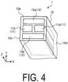
- FIG. 4 is an enlarged perspective view illustrating the configuration of the body portion 10 on the tip portion 10a side according to the embodiment
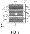
- FIG. 5 is a cross-sectional view illustrating the configuration of the body portion 10 on the tip portion 10a side according to the embodiment.
- FIG. 5 is a cross-sectional view taken along line I-I of FIG. 1 .
- the body portion 10 includes a first piezoelectric element 11 and a second piezoelectric element 12.
- the first piezoelectric element 11 and the second piezoelectric element 12 are disposed on the tip portion 10a side of the body portion 10.
- the first piezoelectric element 11 is a piezoelectric element that displaces the tip portion 10a of the body portion 10 in the X-axis direction, and includes a first element 11a and a second element 11b.
- the first element 11a is disposed on the X-axis positive direction side (that is, the side surface 10d side), and the second element 11b is disposed on the X-axis negative direction side (that is, the side surface 10c side).
- the second piezoelectric element 12 is a piezoelectric element that displaces the tip portion 10a of the body portion 10 in the Y-axis direction, and includes a first element 12a and a second element 12b.
- the first element 12a is disposed on the Y-axis positive direction side
- the second element 12b is disposed on the Y-axis negative direction side.
- the body portion 10 is formed by layering the piezoelectric layer 9 and the internal electrode layers A to E in a predetermined order along the Y-axis direction.
- the first element 12a of the second piezoelectric element 12 is formed by repeatedly layering the piezoelectric layer 9, the internal electrode layer D, the piezoelectric layer 9, and the internal electrode layer E in this order from the Y-axis positive direction side in the body portion 10.
- the first element 12a includes the piezoelectric layer 9, the internal electrode layer D1, and the internal electrode layer E1.
- the first element 11a and the second element 11b of the first piezoelectric element 11 are formed by repeatedly layering the piezoelectric layer 9, the internal electrode layer C, the piezoelectric layer 9, and the internal electrode layer A in this order.
- the first element 11a includes the piezoelectric layer 9, the internal electrode layer C2, and the internal electrode layer A1.
- the second element 11b includes the piezoelectric layer 9, the internal electrode layer C1, and the internal electrode layer A1.
- the second element 12b of the second piezoelectric element 12 is formed by repeatedly layering the piezoelectric layer 9, the internal electrode layer B, the piezoelectric layer 9, and the internal electrode layer D in this order.
- the second element 12b includes the piezoelectric layer 9, the internal electrode layer B1, and the internal electrode layer D1.
- the drive voltage is applied between the internal electrode layer C2 and the internal electrode layer A1.
- the drive voltage is applied to the first element 11a of the first piezoelectric element 11 in which the internal electrode layer C2 and the internal electrode layer A1 are alternately layered.
- the first element 11a extends in the Y-axis direction and contracts in the Z-axis direction, so that in the piezoelectric actuator 1, the tip portion 10a of the body portion 10 is displaced to the X-axis positive direction side.
- a predetermined drive voltage is supplied to the terminal 21 (see FIG. 1 ) and the terminal 24, so that the drive voltage is applied between the internal electrode layer C1 and the internal electrode layer A1.
- the drive voltage is applied to the second element 11b of the first piezoelectric element 11 in which the internal electrode layer C1 and the internal electrode layer A1 are alternately layered.
- the second element 11b extends in the Y-axis direction and contracts in the Z-axis direction, so that in the piezoelectric actuator 1, the tip portion 10a of the body portion 10 is displaced to the X-axis negative direction side.
- the tip portion 10a is independently displaced in the X-axis direction.
- a predetermined drive voltage is supplied to the terminals 21 and the terminals 23 (see FIG. 1 ), so that the drive voltage is applied between the internal electrode layer D1 and the internal electrode layer E1.
- the drive voltage is applied to the first element 12a of the second piezoelectric element 12 in which the internal electrode layer D1 and the internal electrode layer E1 are alternately layered.
- the first element 12a extends in the Y-axis direction and contracts in the Z-axis direction, so that in the piezoelectric actuator 1, the tip portion 10a of the body portion 10 is displaced to the Y-axis positive direction side.
- a predetermined drive voltage is supplied to the terminal 22 and the terminal 23, so that the drive voltage is applied between the internal electrode layer B1 and the internal electrode layer D 1.
- the drive voltage is applied to the second element 12b of the second piezoelectric element 12 in which the internal electrode layer B1 and the internal electrode layer D1 are alternately layered.
- the second element 12b extends in the Y-axis direction and contracts in the Z-axis direction, so that in the piezoelectric actuator 1, the tip portion 10a of the body portion 10 is displaced in the Y-axis negative direction.
- the tip portion 10a is independently displaced in the Y-axis direction.
- FIG. 6 is an enlarged perspective view illustrating the configuration of the base end portion 10b side of the body portion 10 according to the embodiment
- FIG. 7 is a cross-sectional view illustrating the configuration of the base end portion 10b side of the body portion 10 according to the embodiment.
- FIG. 7 is a cross-sectional view taken along line II-II of FIG. 1 .
- the body portion 10 includes a third piezoelectric element 13 in addition to the first piezoelectric element 11 and the second piezoelectric element 12 described above.
- the third piezoelectric element 13 is disposed from the center of the body portion 10 to the peripheral edge portion on the base end portion 10b side of the body portion 10.
- the third piezoelectric element 13 is a piezoelectric element that displaces the tip portion 10a of the body portion 10 in the Z-axis direction.
- the third piezoelectric element 13 is formed by layering the piezoelectric layer 9 and the internal electrode layers A to E in a predetermined order along the Y-axis direction.
- the layered structure of the third piezoelectric element 13 is the same as or similar to the layered structure of the first piezoelectric element 11 and the second piezoelectric element 12.
- the piezoelectric layer 9, the internal electrode layer D, the piezoelectric layer 9, and the internal electrode layer E are repeatedly layered in this order from the Y-axis positive direction side in the body portion 10. Subsequently, the piezoelectric layer 9, the internal electrode layer C, the piezoelectric layer 9 and the internal electrode layer A are repeatedly layered in this order. Subsequently, the piezoelectric layer 9, the internal electrode layer B, the piezoelectric layer 9 and the internal electrode layer D are repeatedly layered in this order.
- the third piezoelectric element 13 is composed of: a layered group including the piezoelectric layer 9, the internal electrode layer D3, and the internal electrode layer E3; a layered group including the piezoelectric layer 9, the internal electrode layer A3, and the internal electrode layer C3; and a layered group including the piezoelectric layer 9, the internal electrode layer B2, and the internal electrode layer D3.
- a predetermined drive voltage is supplied to the terminal 22 (see FIG. 1 ) and the terminal 25 (see FIG. 1 ). Accordingly, the drive voltage is applied between the internal electrode layer D3 and the internal electrode layer E3, the drive voltage is also applied between the internal electrode layer A3 and the internal electrode layer C3, and the drive voltage is also applied between the internal electrode layer B2 and the internal electrode layer D3.
- the drive voltage is applied to all the layered groups in the third piezoelectric element 13, and thus the third piezoelectric element 13 expands along the Y-axis direction and contracts along the Z-axis direction.
- the tip portion 10a of the body portion 10 is displaced in the Z-axis negative direction.
- the tip portion 10a is independently displaced in the Z-axis direction.
- the body portion 10 has the first piezoelectric element 11, the second piezoelectric element 12, and the third piezoelectric element 13, so that the tip portion 10a can be displaced in the X-axis direction, the Y-axis direction, and the Z-axis direction.
- the piezoelectric actuator 1 which is more user-friendly can be provided.
- the internal electrode layers A3, B2, C3, D3, and E3 belonging to the third piezoelectric element 13 are located in the same layer as the internal electrode layers A1, C1, C2 belonging to the first piezoelectric element 11 or the internal electrode layers B1, D1, E1 belonging to the second piezoelectric element 12.
- the internal electrode layers A to E can be disposed on the entire surface of the piezoelectric layer 9 without deviation, distortion of the body portion 10 caused by the internal electrode layers A to E being disposed unevenly on a part of the piezoelectric layer 9 can be reduced.
- the displacement accuracy of the piezoelectric actuator 1 can be improved.
- the piezoelectric actuator 1 includes five terminals 21 to 25, and by selectively applying a voltage to the five terminals 21 to 25, the tip portion 10a is independently displaced in the X-axis direction, the Y-axis direction, and the Z-axis direction.
- the piezoelectric actuator 1 in which the number of terminals is minimized, since the tip portion 10a can be independently displaced in the X-axis direction, the Y-axis direction, and the Z-axis direction, the piezoelectric actuator 1 which is more user-friendly can be provided.
- the stress applied to the terminal portion 20 upon the body portion 10 being deformed can be reduced.
- the piezoelectric actuator 1 when the piezoelectric actuator 1 is incorporated into an external device or the like, the side of the base end portion 10b of the body portion 10 is held by a holding member (not illustrated). Thereby, the displacement accuracy of the tip portion 10a can be improved as compared with the case where the tip portion 10a side of the body portion 10 is held by the holding member.
- FIG. 8 is a cross-sectional view taken along line III-III of FIG. 1 , and is a cross-sectional view of a region between the terminal 21 and the terminal 22.
- the internal electrode layer E2 and the internal electrode layer C1 are electrically connected to the terminal 21 at the side surface 10c.
- the internal electrode layer E4, the internal electrode layer C2, and the internal electrode layer B 1 are electrically connected to the terminal 22 at the side surface 10d.
- FIG. 9 is a cross-sectional view taken along line IV-IV of FIG. 1 , and is a cross-sectional view of a region between the terminal 23 and the terminal 24.
- the internal electrode layer D2 is electrically connected to the terminal 23 at the side surface 10c.
- the internal electrode layer A2 is electrically connected to the terminal 24 at the side surface 10d.
- FIG. 10 is a cross-sectional view taken along line V-V of FIG. 1 , and is a cross-sectional view of the terminal 25 and its vicinity. As illustrated in FIG. 10 , the internal electrode layer D3 and the internal electrode layer A3 are electrically connected to the terminal 25 at the side surface 10c.
- a metallized layer may be disposed between the internal electrode layers A to E and the terminals 21 to 25, and the internal electrode layers A to E and the terminals 21 to 25 may be electrically connected to each other via the metallized layer.
- the internal electrode layers A to E and the terminals 21 to 25 can be electrically connected to each other in a favorable manner.
- FIG. 11 is a top view illustrating the overall configuration of the piezoelectric actuator 1 according to the variation of the embodiment
- FIG. 12 is a side view illustrating the overall configuration of the piezoelectric actuator 1 according to the variation of the embodiment.
- the number of terminals in the terminal portion 20 is different from that in the above-described embodiment.
- the terminal portion 20 according to the variation includes six terminals 21 to 26. As illustrated in FIG. 11 , the six terminals 21 to 26 are disposed in the vicinity of a central portion in the extending direction (that is, the Z-axis direction) of the body portion 10.
- the terminals 21, 23, and 25 are disposed on the side surface 10c of the body portion 10 on the X-axis negative direction side, and the terminals 22, 24, and 26 are disposed on the side surface 10d of the body portion 10 on the X-axis positive direction side.
- the terminals 21, 23, and 25 are disposed side by side in this order from the tip portion 10a side along the Z-axis direction, and the terminals 22, 24, and 26 are disposed side by side in this order from the tip portion 10a side along the Z-axis direction.
- the terminal 21 and the terminal 22 are disposed side by side along the X-axis direction
- the terminal 23 and the terminal 24 are disposed side by side along the X-axis direction
- the terminal 25 and the terminal 26 are disposed side by side along the X-axis direction.
- FIG. 13A is a view illustrating the configuration of the internal electrode layer A of the body portion 10 according to the variation of the embodiment. As illustrated in FIG. 13A , the internal electrode layer A according to the variation is layered along the Y-axis direction on the rectangular piezoelectric layer 9 located along the XZ plane.
- the internal electrode layer A includes the internal electrode layers A1 to A3.
- the internal electrode layer A1 is a wide portion formed from the tip portion 10a to a position just before a portion where the terminals 21 and 22 are disposed.
- the internal electrode layer A1 extends, for example, from the vicinity of the side surface 10c to the vicinity of the side surface 10d in the X-axis direction.
- the internal electrode layer A2 is a narrow portion extending from an end portion of the internal electrode layer A1 on the Z-axis negative direction side to the terminal 24, and electrically connects the internal electrode layer A1 and the terminal 24.
- the internal electrode layer A2 is located, for example, in an intermediate portion between the side surface 10c and the side surface 10d in the X-axis direction.
- the internal electrode layer A3 is a wide portion formed between a portion where the terminal 25 is disposed and the base end portion 10b, and is electrically connected to the terminal 25.
- the internal electrode layer A3 extends, for example, from the vicinity of the side surface 10c to the vicinity of the side surface 10d in the X-axis direction.
- FIG. 13B is a view illustrating the configuration of the internal electrode layer B of the body portion 10 according to the variation of the embodiment. As illustrated in FIG. 13B , the internal electrode layer B according to the variation is layered along the Y-axis direction on the rectangular piezoelectric layer 9 located along the XZ plane.
- the internal electrode layer B includes the internal electrode layers B1 and B2.
- the internal electrode layer B 1 is a wide portion formed from the tip portion 10a to a portion where the terminals 21 and 22 are disposed, and is electrically connected to the terminal 22.
- the internal electrode layer B 1 extends, for example, from the vicinity of the side surface 10c to the vicinity of the side surface 10d in the X-axis direction.
- the internal electrode layer B2 is a wide portion formed between a portion where the terminals 25 and 26 are disposed and the base end portion 10b, and is electrically connected to the terminal 26.
- the internal electrode layer B2 extends, for example, from the vicinity of the side surface 10c to the vicinity of the side surface 10d in the X-axis direction.
- FIG. 13C is a view illustrating the configuration of the internal electrode layer C of the body portion 10 according to the variation of the embodiment. As illustrated in FIG. 13C , the internal electrode layer C according to the variation is layered along the Y-axis direction on the rectangular piezoelectric layer 9 located along the XZ plane.
- the internal electrode layer C includes the internal electrode layers C1 to C3.
- the internal electrode layer C1 is a slightly narrow portion formed between the tip portion 10a and a portion where the terminals 21 and 22 are disposed, and is electrically connected to the terminal 21.
- the internal electrode layer C1 extends, for example, in the X-axis direction, from an intermediate portion between the side surface 10c and the side surface 10d to the vicinity of the side surface 10c.
- the internal electrode layer C2 is a slightly narrow portion formed between the tip portion 10a and a portion where the terminals 21 and 22 are disposed, and is electrically connected to the terminal 22.
- the internal electrode layer C2 extends, for example, in the X-axis direction, from an intermediate portion between the side surface 10c and the side surface 10d to the vicinity of the side surface 10d.
- the internal electrode layer C3 is a wide portion formed between a portion where the terminal 25 are disposed and the base end portion 10b, and is electrically connected to the terminal 26.
- the internal electrode layer C3 extends, for example, from the vicinity of the side surface 10c to the vicinity of the side surface 10d in the X-axis direction.
- FIG. 13D is a view illustrating the configuration of the internal electrode layer D of the body portion 10 according to the variation of the embodiment. As illustrated in FIG. 13D , the internal electrode layer D according to the variation is layered along the Y-axis direction on the rectangular piezoelectric layer 9 located along the XZ plane.
- the internal electrode layer D includes the internal electrode layers D1 to D3.
- the internal electrode layer D1 is a wide portion formed from the tip portion 10a to a position just before a portion where the terminals 21 and 22 are disposed.
- the internal electrode layer D 1 extends, for example, from the vicinity of the side surface 10c to the vicinity of the side surface 10d in the X-axis direction.
- the internal electrode layer D2 is a narrow portion extending from an end portion of the internal electrode layer D1 on the Z-axis negative direction side to the terminal 23, and electrically connects the internal electrode layer D1 and the terminal 23.
- the internal electrode layer D2 is located, for example, in an intermediate portion between the side surface 10c and the side surface 10d in the X-axis direction.
- the internal electrode layer D3 is a wide portion formed between a portion where the terminal 25 is disposed and the base end portion 10b, and is electrically connected to the terminal 25.
- the internal electrode layer D3 extends, for example, from the vicinity of the side surface 10c to the vicinity of the side surface 10d in the X-axis direction.
- FIG. 13E is a view illustrating the configuration of the internal electrode layer E of the body portion 10 according to the variation of the embodiment. As illustrated in FIG. 13E , the internal electrode layer E according to the variation is layered along the Y-axis direction on the rectangular piezoelectric layer 9 located along the XZ plane.
- the internal electrode layer E includes the internal electrode layers E1 to E3.
- the internal electrode layer E1 is a wide portion formed from the tip portion 10a to a position just before a portion where the terminals 21 and 22 are disposed.
- the internal electrode layer E1 extends, for example, from the vicinity of the side surface 10c to the vicinity of the side surface 10d in the X-axis direction.
- the internal electrode layer E2 is a slightly narrow portion extending from an end portion of the internal electrode layer E1 on the Z-axis negative direction side to the terminal 21, and electrically connects the internal electrode layer E1 and the terminal 21.
- the internal electrode layer E2 extends, for example, in the X-axis direction, from an intermediate portion between the side surface 10c and the side surface 10d to the vicinity of the side surface 10c.
- the internal electrode layer E3 is a wide portion formed between a portion where the terminals 25 and 26 are disposed and the base end portion 10b, and is electrically connected to the terminal 26.
- the internal electrode layer E3 extends, for example, from the vicinity of the side surface 10c to the vicinity of the side surface 10d in the X-axis direction.
- the body portion 10 is formed by layering the piezoelectric layer 9 and the internal electrode layers A to E in a predetermined order along the Y-axis direction.
- the first element 12a of the second piezoelectric element 12 is formed by repeatedly layering the piezoelectric layer 9, the internal electrode layer D, the piezoelectric layer 9, and the internal electrode layer E in this order from the Y-axis positive direction side in the body portion 10.
- the first element 12a includes the piezoelectric layer 9, the internal electrode layer D1, and the internal electrode layer E1.
- the first element 11a and the second element 11b of the first piezoelectric element 11 are formed by repeatedly layering the piezoelectric layer 9, the internal electrode layer C, the piezoelectric layer 9, and the internal electrode layer A in this order.
- the first element 11a includes the piezoelectric layer 9, the internal electrode layer C2, and the internal electrode layer A1.
- the second element 11b includes the piezoelectric layer 9, the internal electrode layer C1, and the internal electrode layer A1.
- the second element 12b of the second piezoelectric element 12 is formed by repeatedly layering the piezoelectric layer 9, the internal electrode layer B, the piezoelectric layer 9, and the internal electrode layer D in this order.
- the second element 12b includes the piezoelectric layer 9, the internal electrode layer B1, and the internal electrode layer D1.
- a predetermined drive voltage is supplied to the terminal 22 and the terminal 24, so that the drive voltage is applied between the internal electrode layer C2 and the internal electrode layer A1.
- the drive voltage is applied to the first element 11a of the first piezoelectric element 11 in which the internal electrode layer C2 and the internal electrode layer A1 are alternately layered.
- the first element 11a extends in the Y-axis direction and contracts in the Z-axis direction, so that in the piezoelectric actuator 1, the tip portion 10a of the body portion 10 is displaced to the X-axis positive direction side.
- a predetermined drive voltage is supplied to the terminal 21 and the terminal 24, so that the drive voltage is applied between the internal electrode layer C1 and the internal electrode layer A1.
- the drive voltage is applied to the second element 11b of the first piezoelectric element 11 in which the internal electrode layer C1 and the internal electrode layer A1 are alternately layered.
- the second element 11b extends in the Y-axis direction and contracts in the Z-axis direction, so that in the piezoelectric actuator 1, the tip portion 10a of the body portion 10 is displaced to the X-axis negative direction side.
- the tip portion 10a is independently displaced in the X-axis direction.
- a predetermined drive voltage is supplied to the terminal 21 and the terminal 23, so that the drive voltage is applied between the internal electrode layer D1 and the internal electrode layer E1.
- the drive voltage is applied to the first element 12a of the second piezoelectric element 12 in which the internal electrode layer D1 and the internal electrode layer E1 are alternately layered.
- the first element 12a extends in the Y-axis direction and contracts in the Z-axis direction, so that in the piezoelectric actuator 1, the tip portion 10a of the body portion 10 is displaced to the Y-axis positive direction side.
- a predetermined drive voltage is supplied to the terminal 22 and the terminal 23, so that the drive voltage is applied between the internal electrode layer B1 and the internal electrode layer D 1.
- the drive voltage is applied to the second element 12b of the second piezoelectric element 12 in which the internal electrode layer B1 and the internal electrode layer D1 are alternately layered.
- the second element 12b extends in the Y-axis direction and contracts in the Z-axis direction, so that in the piezoelectric actuator 1, the tip portion 10a of the body portion 10 is displaced in the Y-axis negative direction.
- the tip portion 10a is independently displaced in the Y-axis direction.
- the third piezoelectric element 13 is formed by layering the piezoelectric layer 9 and the internal electrode layers A to E in a predetermined order along the Y-axis direction.
- the layered structure of the third piezoelectric element 13 is the same as or similar to the layered structure of the first piezoelectric element 11 and the second piezoelectric element 12.
- the piezoelectric layer 9, the internal electrode layer D, the piezoelectric layer 9, and the internal electrode layer E are repeatedly layered in this order from the Y-axis positive direction side in the body portion 10. Subsequently, the piezoelectric layer 9, the internal electrode layer C, the piezoelectric layer 9 and the internal electrode layer A are repeatedly layered in this order. Subsequently, the piezoelectric layer 9, the internal electrode layer B, the piezoelectric layer 9 and the internal electrode layer D are repeatedly layered in this order.
- the third piezoelectric element 13 is composed of: a layered group including the piezoelectric layer 9, the internal electrode layer D3, and the internal electrode layer E3; a layered group including the piezoelectric layer 9, the internal electrode layer A3, and the internal electrode layer C3; and a layered group including the piezoelectric layer 9, the internal electrode layer B2, and the internal electrode layer D3.
- a predetermined drive voltage is supplied to the terminal 25 and the terminal 26. Accordingly, the drive voltage is applied between the internal electrode layer D3 and the internal electrode layer E3, the drive voltage is also applied between the internal electrode layer A3 and the internal electrode layer C3, and the drive voltage is also applied between the internal electrode layer B2 and the internal electrode layer D3.
- the drive voltage is applied to all the layered groups in the third piezoelectric element 13, and thus the third piezoelectric element 13 expands along the Y-axis direction and contracts along the Z-axis direction.
- the tip portion 10a of the body portion 10 is displaced in the Z-axis negative direction.
- the tip portion 10a is independently displaced in the Z-axis direction.
- the tip portion 10a is independently displaced in the X-axis direction, the Y-axis direction, and the Z-axis direction by selectively applying a voltage to the six terminals 21 to 26. Accordingly, the piezoelectric actuator 1 which is more user-friendly can be provided.
- the internal electrode layers A3, B2, C3, D3, and E3 belonging to the third piezoelectric element 13 are located in the same layer as the internal electrode layers A1, C1, and C2 belonging to the first piezoelectric element 11 or the internal electrode layers B1, D1, and E1 belonging to the second piezoelectric element 12.
- the internal electrode layers A to E can be disposed on the entire surface of the piezoelectric layer 9 without deviation, distortion of the body portion 10 caused by the internal electrode layers A to E being disposed unevenly on a part of the piezoelectric layer 9 can be reduced.
- the displacement accuracy of the piezoelectric actuator 1 can be improved.
- the piezoelectric actuator 1 when the piezoelectric actuator 1 is incorporated into an external device or the like, the side of the base end portion 10b of the body portion 10 is held by a holding member (not illustrated). Thereby, the displacement accuracy of the tip portion 10a can be improved as compared with the case where the tip portion 10a side of the body portion 10 is held by the holding member.
- the piezoelectric actuator 1 includes the body portion 10 including a layered piezoelectric element layered in a Y-axis direction of an orthogonal coordinate system XYZ, the body portion 10 extending along a Z-axis direction.
- the body portion 10 includes a first piezoelectric element 11 that displaces a tip portion 10a in an X-axis direction, a second piezoelectric element 12 that displaces the tip portion 10a in the Y-axis direction, and a third piezoelectric element 13 that displaces the tip portion 10a in the Z-axis direction. Accordingly, the piezoelectric actuator 1 which is more user-friendly can be provided.
- the internal electrode layers A3, B2, C3, D3, and E3 belonging to the third piezoelectric element 13 are located in the same layer as the internal electrode layers A1, C1, and C2 belonging to the first piezoelectric element 11 or the internal electrode layers B1, D1, and E1 belonging to the second piezoelectric element 12.
- the displacement accuracy of the piezoelectric actuator 1 can be improved.
- the piezoelectric actuator 1 further includes five terminals 21 to 25 that apply a voltage to at least one selected from the group consisting of the first piezoelectric element 11, the second piezoelectric element 12, and the third piezoelectric element 13.
- the tip portion 10a is independently displaced in the X-axis direction, the Y-axis direction, and the Z-axis direction by selectively applying a voltage to the five terminals 21 to 25. Accordingly, the piezoelectric actuator 1 which is more user-friendly can be provided.
- the third piezoelectric element 13 is located closer to the base end portion 10b side of the body portion 10 than the first piezoelectric element 11 and the second piezoelectric element 12.
- the base end portion 10b side of the body portion 10 is held by the holding member.
- the present disclosure is not limited to the embodiments described above, and various modifications can be made without departing from the spirit thereof.
- the body portion 10 has a rectangular parallelepiped shape has been described, but the body portion 10 is not limited to the rectangular parallelepiped shape, and may have a cylindrical shape, a polygonal columnar shape, or the like.
Landscapes
- General Electrical Machinery Utilizing Piezoelectricity, Electrostriction Or Magnetostriction (AREA)
Abstract
Description
- The disclosed embodiments relate to a piezoelectric actuator.
- In the related art, in a piezoelectric actuator extending in a rod shape, a technique is known in which a tip portion can be displaced in a direction substantially perpendicular to an extending direction by selectively applying a voltage to a plurality of terminals (for example, see Patent Document 1).
- Patent Document 1:
JP 2004-531189 T - An object of one aspect of the embodiments is to provide a more user-friendly piezoelectric actuator.
- A piezoelectric actuator according to an aspect of an embodiment includes a body portion including a layered piezoelectric element layered in a Y-axis direction of an orthogonal coordinate system XYZ, the body portion extending along a Z-axis direction. The body portion includes a first piezoelectric element that displaces a tip portion in an X-axis direction, a second piezoelectric element that displaces the tip portion in the Y-axis direction, and a third piezoelectric element that displaces the tip portion in the Z-axis direction.
-
-
FIG. 1 is a top view illustrating an overall configuration of a piezoelectric actuator according to an embodiment. -
FIG. 2 is a side view illustrating an overall configuration of the piezoelectric actuator according to the embodiment. -
FIG. 3A is a diagram illustrating a configuration of an internal electrode layer of a body portion according to the embodiment. -
FIG. 3B is a diagram illustrating the configuration of the internal electrode layer of the body portion according to the embodiment. -
FIG. 3C is a diagram illustrating the configuration of the internal electrode layer of the body portion according to the embodiment. -
FIG. 3D is a diagram illustrating the configuration of the internal electrode layer of the body portion according to the embodiment. -
FIG. 3E is a diagram illustrating the configuration of the internal electrode layer of the body portion according to the embodiment. -
FIG. 4 is an enlarged perspective view illustrating a configuration of a tip portion side of the body portion according to the embodiment. -
FIG. 5 is a cross-sectional view illustrating the configuration of the tip portion side of the body portion according to the embodiment. -
FIG. 6 is an enlarged perspective view illustrating a configuration of a base end portion side of the body portion according to the embodiment. -
FIG. 7 is a cross-sectional view illustrating the configuration of the base end portion side of the body portion according to the embodiment. -
FIG. 8 is a cross-sectional view taken along line III-III inFIG. 1 . -
FIG. 9 is a cross-sectional view taken along line IV-IV inFIG. 1 . -
FIG. 10 is a cross-sectional view taken along line V-V inFIG. 1 . -
FIG. 11 is a top view illustrating an overall configuration of the piezoelectric actuator according to a variation of the embodiment. -
FIG. 12 is a side view illustrating an overall configuration of the piezoelectric actuator according to the variation of the embodiment. -
FIG. 13A is a view illustrating a configuration of an internal electrode layer of a body portion according to the variation of the embodiment. -
FIG. 13B is a view illustrating the configuration of the internal electrode layer of the body portion according to the variation of the embodiment. -
FIG. 13C is a view illustrating the configuration of the internal electrode layer of the body portion according to the variation of the embodiment. -
FIG. 13D is a view illustrating the configuration of the internal electrode layer of the body portion according to the variation of the embodiment. -
FIG. 13E is a view illustrating the configuration of the internal electrode layer of the body portion according to the variation of the embodiment. - Hereinafter, embodiments of a piezoelectric actuator disclosed in the present application will be described with reference to the accompanying drawings. Note that the present disclosure is not limited to the embodiments described below. Note that the drawings are schematic and that the dimensional relationships between elements, the proportions thereof, and the like may differ from the actual ones. The drawings may include portions having different dimensional relationships or ratios.
- In the related art, in a piezoelectric actuator extending in a rod shape, a technique is known in which a tip portion can be displaced in a direction substantially perpendicular to an extending direction by selectively applying a voltage to a plurality of terminals.
- However, in the related art, the direction in which the tip portion can be displaced is limited, leaving room for further improvement in the usability of the piezoelectric actuator.
- Therefore, it is hoped that a technique capable of overcoming the above-described problem and suppressing the usability of the piezoelectric actuator from being further improved will be realized.
- First, an overall configuration of a
piezoelectric actuator 1 according to an embodiment will be described with reference toFIGs. 1 and2 .FIG. 1 is a top view illustrating the overall configuration of thepiezoelectric actuator 1 according to the embodiment, andFIG. 2 is a side view illustrating the overall configuration of thepiezoelectric actuator 1 according to the embodiment. In the following description, in order to clarify the positional relationship, an X-axis, a Y-axis, and a Z axis orthogonal to each other are defined. - As illustrated in
FIGs. 1 and2 , thepiezoelectric actuator 1 according to the embodiment includes abody portion 10 and aterminal portion 20. Thebody portion 10 is a rod-like (for example, rectangular parallelepiped) portion extending along the Z-axis direction, and has atip portion 10a, which is an end portion on the Z-axis positive direction side, and abase end portion 10b, which is an end portion on the Z-axis negative direction side. - The
body portion 10 includes a layered piezoelectric element including a piezoelectric layer 9 (seeFIG. 3A ) and internal electrode layers A to E (seeFIG. 3A to FIG. 3E ), and layered in the Y-axis direction. The details of the layered piezoelectric element will be described below. - The
terminal portion 20 supplies a drive voltage from the outside to the layered piezoelectric element of thebody portion 10. Theterminal portion 20 according to the embodiment includes fiveterminals 21 to 25. As illustrated inFIG. 1 , the fiveterminals 21 to 25 are disposed in the vicinity of a central portion in the extending direction (that is, the Z-axis direction) of thebody portion 10. - The
terminals side surface 10c of thebody portion 10 on the X-axis negative direction side, and theterminals side surface 10d of thebody portion 10 on the X-axis positive direction side. Theterminals tip portion 10a side along the Z-axis direction, and theterminals tip portion 10a side along the Z-axis direction. - The terminal 21 and the terminal 22 are disposed side by side along the X-axis direction, and the terminal 23 and the terminal 24 are disposed side by side along the X-axis direction.
- The material of the
terminals 21 to 25 is, for example, a metal such as copper, iron, stainless steel, or phosphor bronze, and the thickness of theterminals 21 to 25 is, for example, from 0.01 (mm) to 1.0 (mm). A plating film such as tin plating or silver plating may be provided on the surface of each of theterminals 21 to 25 in order to improve electrical conductivity and thermal conductivity. - Next, an internal configuration of the
body portion 10 according to the embodiment will be described with reference toFIGs. 3A to 10 . First, the configuration of thepiezoelectric layer 9 and the internal electrode layers A to E constituting the layered piezoelectric element of thebody portion 10 will be described with reference toFIGs. 3A and3E . -
FIG. 3A is a view illustrating the configuration of the internal electrode layer A of thebody portion 10 according to the embodiment. As illustrated inFIG. 3A , the internal electrode layer A is layered along the Y-axis direction on the rectangularpiezoelectric layer 9 located along the XZ plane. - The internal electrode layer A has internal electrode layers A1 to A3. The internal electrode layer A1 is a wide portion formed from the
tip portion 10a to a position just before a portion where theterminals side surface 10c to the vicinity of theside surface 10d in the X-axis direction. - The internal electrode layer A2 is a narrow portion extending from an end portion of the internal electrode layer A1 on the Z-axis negative direction side to the terminal 24, and electrically connects the internal electrode layer A1 and the terminal 24. The internal electrode layer A2 is located, for example, in an intermediate portion between the
side surface 10c and theside surface 10d in the X-axis direction. - The internal electrode layer A3 is a wide portion formed between a portion where a terminal 25 is disposed and the
base end portion 10b, and is electrically connected to the terminal 25. The internal electrode layer A3 extends, for example, from the vicinity of theside surface 10c to the vicinity of theside surface 10d in the X-axis direction. - The
piezoelectric layer 9 is made of a piezoelectric material having piezoelectric characteristics, for example, a piezoelectric ceramic. The material of the piezoelectric ceramic is, for example, a perovskite-type oxide made of lead zirconate titanate (PbZrO3-PbTiO3), lithium niobate (LiNbO3), or lithium tantalate (LiTaOs). - The average particle diameter of the piezoelectric ceramic is, for example, 1.6 (µm) to 2.8 (µm). The thickness of the
piezoelectric layer 9 is, for example, 3 (µm) to 250 (µm). - The material of the internal electrode layers A to E is, for example, a metal containing silver, silver-palladium, silver-platinum, copper, or the like as a main component. The internal electrode layers A to E can be formed by, for example, co-firing with the
piezoelectric layer 9. The thickness of the internal electrode layers A to E is, for example, 0.1 (µm) to 5 (µm). -
FIG. 3B is a view illustrating the configuration of the internal electrode layer B of thebody portion 10 according to the embodiment. As illustrated inFIG. 3B , the internal electrode layer B is layered along the Y-axis direction on the rectangularpiezoelectric layer 9 located along the XZ plane. - The internal electrode layer B includes internal electrode layers B1 and B2. The internal electrode layer B1 is a wide portion formed from the
tip portion 10a to a portion where theterminals side surface 10c to the vicinity of theside surface 10d in the X-axis direction. - The internal electrode layer B2 is a wide portion formed between a portion where the
terminals base end portion 10b, and is electrically connected to the terminal 22. The internal electrode layer B2 extends, for example, from the vicinity of theside surface 10c to the vicinity of theside surface 10d in the X-axis direction. - As described above, the internal electrode layers B1 and B2 are electrically connected to the terminal 22, and are integrally formed on substantially the entire surface of the rectangular
piezoelectric layer 9. -
FIG. 3C is a view illustrating the configuration of the internal electrode layer C of thebody portion 10 according to the embodiment. As illustrated inFIG. 3C , the internal electrode layer C is layered along the Y-axis direction on the rectangularpiezoelectric layer 9 located along the XZ plane. - The internal electrode layer C includes internal electrode layers C1 to C4. The internal electrode layer C1 is a slightly narrow portion formed between the
tip portion 10a and a portion where theterminals side surface 10c and theside surface 10d to the vicinity of theside surface 10c. - The internal electrode layer C2 is a slightly narrow portion formed between the
tip portion 10a and a portion where theterminals side surface 10c and theside surface 10d to the vicinity of theside surface 10d. - The internal electrode layer C3 is a wide portion formed between a portion where the terminal 25 is disposed and the
base end portion 10b. The internal electrode layer C3 extends, for example, from the vicinity of theside surface 10c to the vicinity of theside surface 10d in the X-axis direction. - The internal electrode layer C4 is a slightly narrow portion extending from an end portion of the internal electrode layer C2 on the Z-axis negative direction side to an end portion of the internal electrode layer C3 on the Z-axis positive direction side, and electrically connects the internal electrode layer C3 and the terminal 22. The internal electrode layer C4 extends from an intermediate portion between the
side surface 10c and theside surface 10d to the vicinity of theside surface 10d. -
FIG. 3D is a view illustrating the configuration of the internal electrode layer D of thebody portion 10 according to the embodiment. As illustrated inFIG. 3D , the internal electrode layer D is layered along the Y-axis direction on the rectangularpiezoelectric layer 9 located along the XZ plane. - The internal electrode layer D includes internal electrode layers D1 to D3. The internal electrode layer D1 is a wide portion formed from the
tip portion 10a to a position just before a portion where theterminals side surface 10c to the vicinity of theside surface 10d in the X-axis direction. - The internal electrode layer D2 is a narrow portion extending from an end portion of the internal electrode layer D1 on the Z-axis negative direction side to the terminal 23, and electrically connects the internal electrode layer D1 and the terminal 23. The internal electrode layer D2 is located, for example, in an intermediate portion between the
side surface 10c and theside surface 10d in the X-axis direction. - The internal electrode layer D3 is a wide portion formed between a portion where the terminal 25 is disposed and the
base end portion 10b, and is electrically connected to the terminal 25. The internal electrode layer D3 extends, for example, from the vicinity of theside surface 10c to the vicinity of theside surface 10d in the X-axis direction. -
FIG. 3E is a view illustrating the configuration of the internal electrode layer E of thebody portion 10 according to the embodiment. As illustrated inFIG. 3E , the internal electrode layer E is layered along the Y-axis direction on the rectangularpiezoelectric layer 9 located along the XZ plane. - The internal electrode layer E includes internal electrode layers E1 to E4. The internal electrode layer E1 is a wide portion formed from the
tip portion 10a to a position just before a portion where theterminals side surface 10c to the vicinity of theside surface 10d in the X-axis direction. - The internal electrode layer E2 is a slightly narrow portion extending from an end portion of the internal electrode layer E1 on the Z-axis negative direction side to the terminal 21, and electrically connects the internal electrode layer E1 and the terminal 21. The internal electrode layer E2 extends, for example, in the X-axis direction, from an intermediate portion between the
side surface 10c and theside surface 10d to the vicinity of theside surface 10c. - The internal electrode layer E3 is a wide portion formed between a portion where the terminal 25 is disposed and the
base end portion 10b. The internal electrode layer E3 extends, for example, from the vicinity of theside surface 10c to the vicinity of theside surface 10d in the X-axis direction. - The internal electrode layer E4 is a slightly narrow portion extending from a portion where the terminal 22 is disposed to an end portion of the internal electrode layer E3 on the Z-axis positive direction side, and electrically connects the internal electrode layer E3 and the terminal 22. The internal electrode layer E4 extends, for example, from an intermediate portion between the
side surface 10c and theside surface 10d to the vicinity of theside surface 10d. - Next, details of the layered piezoelectric element of the
body portion 10 including thepiezoelectric layer 9 and the internal electrode layers A to E described above will be described with reference toFIGs. 4 to 10 . -
FIG. 4 is an enlarged perspective view illustrating the configuration of thebody portion 10 on thetip portion 10a side according to the embodiment, andFIG. 5 is a cross-sectional view illustrating the configuration of thebody portion 10 on thetip portion 10a side according to the embodiment.FIG. 5 is a cross-sectional view taken along line I-I ofFIG. 1 . - As illustrated in
FIG. 4 , thebody portion 10 according to the embodiment includes a firstpiezoelectric element 11 and a secondpiezoelectric element 12. The firstpiezoelectric element 11 and the secondpiezoelectric element 12 are disposed on thetip portion 10a side of thebody portion 10. - The first
piezoelectric element 11 is a piezoelectric element that displaces thetip portion 10a of thebody portion 10 in the X-axis direction, and includes afirst element 11a and asecond element 11b. Thefirst element 11a is disposed on the X-axis positive direction side (that is, theside surface 10d side), and thesecond element 11b is disposed on the X-axis negative direction side (that is, theside surface 10c side). - The second
piezoelectric element 12 is a piezoelectric element that displaces thetip portion 10a of thebody portion 10 in the Y-axis direction, and includes afirst element 12a and asecond element 12b. Thefirst element 12a is disposed on the Y-axis positive direction side, and thesecond element 12b is disposed on the Y-axis negative direction side. - As illustrated in
FIG. 5 , thebody portion 10 is formed by layering thepiezoelectric layer 9 and the internal electrode layers A to E in a predetermined order along the Y-axis direction. To be specific, thefirst element 12a of the secondpiezoelectric element 12 is formed by repeatedly layering thepiezoelectric layer 9, the internal electrode layer D, thepiezoelectric layer 9, and the internal electrode layer E in this order from the Y-axis positive direction side in thebody portion 10. Thefirst element 12a includes thepiezoelectric layer 9, the internal electrode layer D1, and the internal electrode layer E1. - Following the
first element 12a, thefirst element 11a and thesecond element 11b of the firstpiezoelectric element 11 are formed by repeatedly layering thepiezoelectric layer 9, the internal electrode layer C, thepiezoelectric layer 9, and the internal electrode layer A in this order. - The
first element 11a includes thepiezoelectric layer 9, the internal electrode layer C2, and the internal electrode layer A1. Thesecond element 11b includes thepiezoelectric layer 9, the internal electrode layer C1, and the internal electrode layer A1. - Further, following the first
piezoelectric element 11, thesecond element 12b of the secondpiezoelectric element 12 is formed by repeatedly layering thepiezoelectric layer 9, the internal electrode layer B, thepiezoelectric layer 9, and the internal electrode layer D in this order. Thesecond element 12b includes thepiezoelectric layer 9, the internal electrode layer B1, and the internal electrode layer D1. - In the
piezoelectric actuator 1 described above, by supplying a predetermined drive voltage to the terminal 22 (seeFIG. 1 ) and the terminal 24 (seeFIG. 1 ), the drive voltage is applied between the internal electrode layer C2 and the internal electrode layer A1. - That is, by supplying a drive voltage to the
terminals first element 11a of the firstpiezoelectric element 11 in which the internal electrode layer C2 and the internal electrode layer A1 are alternately layered. As a result, thefirst element 11a extends in the Y-axis direction and contracts in the Z-axis direction, so that in thepiezoelectric actuator 1, thetip portion 10a of thebody portion 10 is displaced to the X-axis positive direction side. - In the
piezoelectric actuator 1 according to the embodiment, a predetermined drive voltage is supplied to the terminal 21 (seeFIG. 1 ) and the terminal 24, so that the drive voltage is applied between the internal electrode layer C1 and the internal electrode layer A1. - That is, by supplying a drive voltage to the
terminals second element 11b of the firstpiezoelectric element 11 in which the internal electrode layer C1 and the internal electrode layer A1 are alternately layered. As a result, thesecond element 11b extends in the Y-axis direction and contracts in the Z-axis direction, so that in thepiezoelectric actuator 1, thetip portion 10a of thebody portion 10 is displaced to the X-axis negative direction side. - In this manner, in the embodiment, by selectively applying a voltage to the
terminals tip portion 10a is independently displaced in the X-axis direction. - In the
piezoelectric actuator 1 according to the embodiment, a predetermined drive voltage is supplied to theterminals 21 and the terminals 23 (seeFIG. 1 ), so that the drive voltage is applied between the internal electrode layer D1 and the internal electrode layer E1. - That is, by supplying a drive voltage to the
terminals first element 12a of the secondpiezoelectric element 12 in which the internal electrode layer D1 and the internal electrode layer E1 are alternately layered. As a result, thefirst element 12a extends in the Y-axis direction and contracts in the Z-axis direction, so that in thepiezoelectric actuator 1, thetip portion 10a of thebody portion 10 is displaced to the Y-axis positive direction side. - In the
piezoelectric actuator 1 according to the embodiment, a predetermined drive voltage is supplied to the terminal 22 and the terminal 23, so that the drive voltage is applied between the internal electrode layer B1 and the internalelectrode layer D 1. - That is, by supplying a drive voltage to the
terminals second element 12b of the secondpiezoelectric element 12 in which the internal electrode layer B1 and the internal electrode layer D1 are alternately layered. As a result, thesecond element 12b extends in the Y-axis direction and contracts in the Z-axis direction, so that in thepiezoelectric actuator 1, thetip portion 10a of thebody portion 10 is displaced in the Y-axis negative direction. - In this manner, in the embodiment, by selectively applying a voltage to the
terminals 21 to 23, thetip portion 10a is independently displaced in the Y-axis direction. -
FIG. 6 is an enlarged perspective view illustrating the configuration of thebase end portion 10b side of thebody portion 10 according to the embodiment, andFIG. 7 is a cross-sectional view illustrating the configuration of thebase end portion 10b side of thebody portion 10 according to the embodiment.FIG. 7 is a cross-sectional view taken along line II-II ofFIG. 1 . - As illustrated in
FIG. 6 , thebody portion 10 according to the embodiment includes a thirdpiezoelectric element 13 in addition to the firstpiezoelectric element 11 and the secondpiezoelectric element 12 described above. The thirdpiezoelectric element 13 is disposed from the center of thebody portion 10 to the peripheral edge portion on thebase end portion 10b side of thebody portion 10. The thirdpiezoelectric element 13 is a piezoelectric element that displaces thetip portion 10a of thebody portion 10 in the Z-axis direction. - As illustrated in
FIG. 7 , the thirdpiezoelectric element 13 is formed by layering thepiezoelectric layer 9 and the internal electrode layers A to E in a predetermined order along the Y-axis direction. The layered structure of the thirdpiezoelectric element 13 is the same as or similar to the layered structure of the firstpiezoelectric element 11 and the secondpiezoelectric element 12. - That is, as illustrated in
FIG. 7 , thepiezoelectric layer 9, the internal electrode layer D, thepiezoelectric layer 9, and the internal electrode layer E are repeatedly layered in this order from the Y-axis positive direction side in thebody portion 10. Subsequently, thepiezoelectric layer 9, the internal electrode layer C, thepiezoelectric layer 9 and the internal electrode layer A are repeatedly layered in this order. Subsequently, thepiezoelectric layer 9, the internal electrode layer B, thepiezoelectric layer 9 and the internal electrode layer D are repeatedly layered in this order. - The third
piezoelectric element 13 is composed of: a layered group including thepiezoelectric layer 9, the internal electrode layer D3, and the internal electrode layer E3; a layered group including thepiezoelectric layer 9, the internal electrode layer A3, and the internal electrode layer C3; and a layered group including thepiezoelectric layer 9, the internal electrode layer B2, and the internal electrode layer D3. - In the
piezoelectric actuator 1 having such an internal configuration, a predetermined drive voltage is supplied to the terminal 22 (seeFIG. 1 ) and the terminal 25 (seeFIG. 1 ). Accordingly, the drive voltage is applied between the internal electrode layer D3 and the internal electrode layer E3, the drive voltage is also applied between the internal electrode layer A3 and the internal electrode layer C3, and the drive voltage is also applied between the internal electrode layer B2 and the internal electrode layer D3. - That is, by supplying the drive voltage to the terminal 22 and the terminal 25, the drive voltage is applied to all the layered groups in the third
piezoelectric element 13, and thus the thirdpiezoelectric element 13 expands along the Y-axis direction and contracts along the Z-axis direction. As a result, in thepiezoelectric actuator 1, thetip portion 10a of thebody portion 10 is displaced in the Z-axis negative direction. - In this manner, in the embodiment, by selectively applying a voltage to the
terminals tip portion 10a is independently displaced in the Z-axis direction. - As described above, in the
piezoelectric actuator 1 according to the embodiment, thebody portion 10 has the firstpiezoelectric element 11, the secondpiezoelectric element 12, and the thirdpiezoelectric element 13, so that thetip portion 10a can be displaced in the X-axis direction, the Y-axis direction, and the Z-axis direction. - Therefore, according to the embodiment, the
piezoelectric actuator 1 which is more user-friendly can be provided. - In the embodiment, as illustrated in
FIGs. 5 and7 , the internal electrode layers A3, B2, C3, D3, and E3 belonging to the thirdpiezoelectric element 13 are located in the same layer as the internal electrode layers A1, C1, C2 belonging to the firstpiezoelectric element 11 or the internal electrode layers B1, D1, E1 belonging to the secondpiezoelectric element 12. - As a result, the internal electrode layers A to E can be disposed on the entire surface of the
piezoelectric layer 9 without deviation, distortion of thebody portion 10 caused by the internal electrode layers A to E being disposed unevenly on a part of thepiezoelectric layer 9 can be reduced. - Therefore, according to the embodiment, the displacement accuracy of the
piezoelectric actuator 1 can be improved. - The
piezoelectric actuator 1 according to the embodiment includes fiveterminals 21 to 25, and by selectively applying a voltage to the fiveterminals 21 to 25, thetip portion 10a is independently displaced in the X-axis direction, the Y-axis direction, and the Z-axis direction. - In this manner, according to the embodiment, in the
piezoelectric actuator 1 in which the number of terminals is minimized, since thetip portion 10a can be independently displaced in the X-axis direction, the Y-axis direction, and the Z-axis direction, thepiezoelectric actuator 1 which is more user-friendly can be provided. - In the embodiment, by minimizing the number of terminals, the stress applied to the
terminal portion 20 upon thebody portion 10 being deformed can be reduced. - In the embodiment, when the
piezoelectric actuator 1 is incorporated into an external device or the like, the side of thebase end portion 10b of thebody portion 10 is held by a holding member (not illustrated). Thereby, the displacement accuracy of thetip portion 10a can be improved as compared with the case where thetip portion 10a side of thebody portion 10 is held by the holding member. - The internal configuration of the
body portion 10 will be further described.FIG. 8 is a cross-sectional view taken along line III-III ofFIG. 1 , and is a cross-sectional view of a region between the terminal 21 and the terminal 22. - As illustrated in
FIG. 8 , the internal electrode layer E2 and the internal electrode layer C1 are electrically connected to the terminal 21 at theside surface 10c. The internal electrode layer E4, the internal electrode layer C2, and the internalelectrode layer B 1 are electrically connected to the terminal 22 at theside surface 10d. -
FIG. 9 is a cross-sectional view taken along line IV-IV ofFIG. 1 , and is a cross-sectional view of a region between the terminal 23 and the terminal 24. As illustrated inFIG. 9 , the internal electrode layer D2 is electrically connected to the terminal 23 at theside surface 10c. The internal electrode layer A2 is electrically connected to the terminal 24 at theside surface 10d. -
FIG. 10 is a cross-sectional view taken along line V-V ofFIG. 1 , and is a cross-sectional view of the terminal 25 and its vicinity. As illustrated inFIG. 10 , the internal electrode layer D3 and the internal electrode layer A3 are electrically connected to the terminal 25 at theside surface 10c. - In the examples of
FIGs. 8 to 10 , examples in which the internal electrode layers A to E and theterminals 21 to 25 are directly connected to each other are illustrated, but a metallized layer may be disposed between the internal electrode layers A to E and theterminals 21 to 25, and the internal electrode layers A to E and theterminals 21 to 25 may be electrically connected to each other via the metallized layer. - Accordingly, the internal electrode layers A to E and the
terminals 21 to 25 can be electrically connected to each other in a favorable manner. - Next, a variation of the embodiment will be described with reference to
FIGs. 11 to 13E . In the variation described below, the same components as those in the embodiment are denoted by the same reference numerals, and redundant description may be omitted. -
FIG. 11 is a top view illustrating the overall configuration of thepiezoelectric actuator 1 according to the variation of the embodiment, andFIG. 12 is a side view illustrating the overall configuration of thepiezoelectric actuator 1 according to the variation of the embodiment. - In this variation, the number of terminals in the
terminal portion 20 is different from that in the above-described embodiment. Specifically, theterminal portion 20 according to the variation includes sixterminals 21 to 26. As illustrated inFIG. 11 , the sixterminals 21 to 26 are disposed in the vicinity of a central portion in the extending direction (that is, the Z-axis direction) of thebody portion 10. - The
terminals side surface 10c of thebody portion 10 on the X-axis negative direction side, and theterminals side surface 10d of thebody portion 10 on the X-axis positive direction side. - The
terminals tip portion 10a side along the Z-axis direction, and theterminals tip portion 10a side along the Z-axis direction. - The terminal 21 and the terminal 22 are disposed side by side along the X-axis direction, the terminal 23 and the terminal 24 are disposed side by side along the X-axis direction, and the terminal 25 and the terminal 26 are disposed side by side along the X-axis direction.
-
FIG. 13A is a view illustrating the configuration of the internal electrode layer A of thebody portion 10 according to the variation of the embodiment. As illustrated inFIG. 13A , the internal electrode layer A according to the variation is layered along the Y-axis direction on the rectangularpiezoelectric layer 9 located along the XZ plane. - The internal electrode layer A according to the variation includes the internal electrode layers A1 to A3. The internal electrode layer A1 is a wide portion formed from the
tip portion 10a to a position just before a portion where theterminals side surface 10c to the vicinity of theside surface 10d in the X-axis direction. - The internal electrode layer A2 is a narrow portion extending from an end portion of the internal electrode layer A1 on the Z-axis negative direction side to the terminal 24, and electrically connects the internal electrode layer A1 and the terminal 24. The internal electrode layer A2 is located, for example, in an intermediate portion between the
side surface 10c and theside surface 10d in the X-axis direction. - The internal electrode layer A3 is a wide portion formed between a portion where the terminal 25 is disposed and the
base end portion 10b, and is electrically connected to the terminal 25. The internal electrode layer A3 extends, for example, from the vicinity of theside surface 10c to the vicinity of theside surface 10d in the X-axis direction. -
FIG. 13B is a view illustrating the configuration of the internal electrode layer B of thebody portion 10 according to the variation of the embodiment. As illustrated inFIG. 13B , the internal electrode layer B according to the variation is layered along the Y-axis direction on the rectangularpiezoelectric layer 9 located along the XZ plane. - The internal electrode layer B according to the variation includes the internal electrode layers B1 and B2. The internal
electrode layer B 1 is a wide portion formed from thetip portion 10a to a portion where theterminals electrode layer B 1 extends, for example, from the vicinity of theside surface 10c to the vicinity of theside surface 10d in the X-axis direction. - The internal electrode layer B2 is a wide portion formed between a portion where the
terminals base end portion 10b, and is electrically connected to the terminal 26. The internal electrode layer B2 extends, for example, from the vicinity of theside surface 10c to the vicinity of theside surface 10d in the X-axis direction. -
FIG. 13C is a view illustrating the configuration of the internal electrode layer C of thebody portion 10 according to the variation of the embodiment. As illustrated inFIG. 13C , the internal electrode layer C according to the variation is layered along the Y-axis direction on the rectangularpiezoelectric layer 9 located along the XZ plane. - The internal electrode layer C according to the variation includes the internal electrode layers C1 to C3. The internal electrode layer C1 is a slightly narrow portion formed between the
tip portion 10a and a portion where theterminals side surface 10c and theside surface 10d to the vicinity of theside surface 10c. - The internal electrode layer C2 is a slightly narrow portion formed between the
tip portion 10a and a portion where theterminals side surface 10c and theside surface 10d to the vicinity of theside surface 10d. - The internal electrode layer C3 is a wide portion formed between a portion where the terminal 25 are disposed and the
base end portion 10b, and is electrically connected to the terminal 26. The internal electrode layer C3 extends, for example, from the vicinity of theside surface 10c to the vicinity of theside surface 10d in the X-axis direction. -
FIG. 13D is a view illustrating the configuration of the internal electrode layer D of thebody portion 10 according to the variation of the embodiment. As illustrated inFIG. 13D , the internal electrode layer D according to the variation is layered along the Y-axis direction on the rectangularpiezoelectric layer 9 located along the XZ plane. - The internal electrode layer D according to the variation includes the internal electrode layers D1 to D3. The internal electrode layer D1 is a wide portion formed from the
tip portion 10a to a position just before a portion where theterminals electrode layer D 1 extends, for example, from the vicinity of theside surface 10c to the vicinity of theside surface 10d in the X-axis direction. - The internal electrode layer D2 is a narrow portion extending from an end portion of the internal electrode layer D1 on the Z-axis negative direction side to the terminal 23, and electrically connects the internal electrode layer D1 and the terminal 23. The internal electrode layer D2 is located, for example, in an intermediate portion between the
side surface 10c and theside surface 10d in the X-axis direction. - The internal electrode layer D3 is a wide portion formed between a portion where the terminal 25 is disposed and the
base end portion 10b, and is electrically connected to the terminal 25. The internal electrode layer D3 extends, for example, from the vicinity of theside surface 10c to the vicinity of theside surface 10d in the X-axis direction. -
FIG. 13E is a view illustrating the configuration of the internal electrode layer E of thebody portion 10 according to the variation of the embodiment. As illustrated inFIG. 13E , the internal electrode layer E according to the variation is layered along the Y-axis direction on the rectangularpiezoelectric layer 9 located along the XZ plane. - The internal electrode layer E according to the variation includes the internal electrode layers E1 to E3. The internal electrode layer E1 is a wide portion formed from the
tip portion 10a to a position just before a portion where theterminals side surface 10c to the vicinity of theside surface 10d in the X-axis direction. - The internal electrode layer E2 is a slightly narrow portion extending from an end portion of the internal electrode layer E1 on the Z-axis negative direction side to the terminal 21, and electrically connects the internal electrode layer E1 and the terminal 21. The internal electrode layer E2 extends, for example, in the X-axis direction, from an intermediate portion between the
side surface 10c and theside surface 10d to the vicinity of theside surface 10c. - The internal electrode layer E3 is a wide portion formed between a portion where the
terminals base end portion 10b, and is electrically connected to the terminal 26. The internal electrode layer E3 extends, for example, from the vicinity of theside surface 10c to the vicinity of theside surface 10d in the X-axis direction. - Next, a variation of the
body portion 10 including thepiezoelectric layer 9 and the internal electrode layers A to E described above will be described. Since the configuration of the layered piezoelectric element according to the variation is the same as or similar to the configuration of the embodiment illustrated inFIGs. 4 to 7 , the operation of each piezoelectric element in the variation will be described below with reference toFIGs. 4 to 7 . - As illustrated in
FIG. 5 , thebody portion 10 according to the variation is formed by layering thepiezoelectric layer 9 and the internal electrode layers A to E in a predetermined order along the Y-axis direction. To be specific, thefirst element 12a of the secondpiezoelectric element 12 is formed by repeatedly layering thepiezoelectric layer 9, the internal electrode layer D, thepiezoelectric layer 9, and the internal electrode layer E in this order from the Y-axis positive direction side in thebody portion 10. Thefirst element 12a includes thepiezoelectric layer 9, the internal electrode layer D1, and the internal electrode layer E1. - Following the
first element 12a, thefirst element 11a and thesecond element 11b of the firstpiezoelectric element 11 are formed by repeatedly layering thepiezoelectric layer 9, the internal electrode layer C, thepiezoelectric layer 9, and the internal electrode layer A in this order. - The
first element 11a includes thepiezoelectric layer 9, the internal electrode layer C2, and the internal electrode layer A1. Thesecond element 11b includes thepiezoelectric layer 9, the internal electrode layer C1, and the internal electrode layer A1. - Further, following the first
piezoelectric element 11, thesecond element 12b of the secondpiezoelectric element 12 is formed by repeatedly layering thepiezoelectric layer 9, the internal electrode layer B, thepiezoelectric layer 9, and the internal electrode layer D in this order. Thesecond element 12b includes thepiezoelectric layer 9, the internal electrode layer B1, and the internal electrode layer D1. - In the
piezoelectric actuator 1 according to the variation, a predetermined drive voltage is supplied to the terminal 22 and the terminal 24, so that the drive voltage is applied between the internal electrode layer C2 and the internal electrode layer A1. - That is, by supplying a drive voltage to the
terminals first element 11a of the firstpiezoelectric element 11 in which the internal electrode layer C2 and the internal electrode layer A1 are alternately layered. As a result, thefirst element 11a extends in the Y-axis direction and contracts in the Z-axis direction, so that in thepiezoelectric actuator 1, thetip portion 10a of thebody portion 10 is displaced to the X-axis positive direction side. - In the
piezoelectric actuator 1 according to the variation, a predetermined drive voltage is supplied to the terminal 21 and the terminal 24, so that the drive voltage is applied between the internal electrode layer C1 and the internal electrode layer A1. - That is, by supplying a drive voltage to the
terminals second element 11b of the firstpiezoelectric element 11 in which the internal electrode layer C1 and the internal electrode layer A1 are alternately layered. As a result, thesecond element 11b extends in the Y-axis direction and contracts in the Z-axis direction, so that in thepiezoelectric actuator 1, thetip portion 10a of thebody portion 10 is displaced to the X-axis negative direction side. - In this manner, in the variation, by selectively applying a voltage to the
terminals tip portion 10a is independently displaced in the X-axis direction. - In the
piezoelectric actuator 1 according to the variation, a predetermined drive voltage is supplied to the terminal 21 and the terminal 23, so that the drive voltage is applied between the internal electrode layer D1 and the internal electrode layer E1. - That is, by supplying a drive voltage to the
terminals first element 12a of the secondpiezoelectric element 12 in which the internal electrode layer D1 and the internal electrode layer E1 are alternately layered. As a result, thefirst element 12a extends in the Y-axis direction and contracts in the Z-axis direction, so that in thepiezoelectric actuator 1, thetip portion 10a of thebody portion 10 is displaced to the Y-axis positive direction side. - In the
piezoelectric actuator 1 according to the variation, a predetermined drive voltage is supplied to the terminal 22 and the terminal 23, so that the drive voltage is applied between the internal electrode layer B1 and the internalelectrode layer D 1. - That is, by supplying a drive voltage to the
terminals second element 12b of the secondpiezoelectric element 12 in which the internal electrode layer B1 and the internal electrode layer D1 are alternately layered. As a result, thesecond element 12b extends in the Y-axis direction and contracts in the Z-axis direction, so that in thepiezoelectric actuator 1, thetip portion 10a of thebody portion 10 is displaced in the Y-axis negative direction. - In this manner, in the variation, by selectively applying a voltage to the
terminals 21 to 23, thetip portion 10a is independently displaced in the Y-axis direction. - As illustrated in
FIG. 7 , the thirdpiezoelectric element 13 according to the variation is formed by layering thepiezoelectric layer 9 and the internal electrode layers A to E in a predetermined order along the Y-axis direction. The layered structure of the thirdpiezoelectric element 13 is the same as or similar to the layered structure of the firstpiezoelectric element 11 and the secondpiezoelectric element 12. - That is, as illustrated in
FIG. 7 , thepiezoelectric layer 9, the internal electrode layer D, thepiezoelectric layer 9, and the internal electrode layer E are repeatedly layered in this order from the Y-axis positive direction side in thebody portion 10. Subsequently, thepiezoelectric layer 9, the internal electrode layer C, thepiezoelectric layer 9 and the internal electrode layer A are repeatedly layered in this order. Subsequently, thepiezoelectric layer 9, the internal electrode layer B, thepiezoelectric layer 9 and the internal electrode layer D are repeatedly layered in this order. - The third
piezoelectric element 13 according to the variation is composed of: a layered group including thepiezoelectric layer 9, the internal electrode layer D3, and the internal electrode layer E3; a layered group including thepiezoelectric layer 9, the internal electrode layer A3, and the internal electrode layer C3; and a layered group including thepiezoelectric layer 9, the internal electrode layer B2, and the internal electrode layer D3. - In the
piezoelectric actuator 1 according to the variation, a predetermined drive voltage is supplied to the terminal 25 and the terminal 26. Accordingly, the drive voltage is applied between the internal electrode layer D3 and the internal electrode layer E3, the drive voltage is also applied between the internal electrode layer A3 and the internal electrode layer C3, and the drive voltage is also applied between the internal electrode layer B2 and the internal electrode layer D3. - That is, by supplying the drive voltage to the terminal 25 and the terminal 26, the drive voltage is applied to all the layered groups in the third
piezoelectric element 13, and thus the thirdpiezoelectric element 13 expands along the Y-axis direction and contracts along the Z-axis direction. As a result, in thepiezoelectric actuator 1, thetip portion 10a of thebody portion 10 is displaced in the Z-axis negative direction. - In this manner, in the variation, by selectively applying a voltage to the
terminals tip portion 10a is independently displaced in the Z-axis direction. - As described above, in the
piezoelectric actuator 1 according to the variation, thetip portion 10a is independently displaced in the X-axis direction, the Y-axis direction, and the Z-axis direction by selectively applying a voltage to the sixterminals 21 to 26. Accordingly, thepiezoelectric actuator 1 which is more user-friendly can be provided. - In the variation, the internal electrode layers A3, B2, C3, D3, and E3 belonging to the third
piezoelectric element 13 are located in the same layer as the internal electrode layers A1, C1, and C2 belonging to the firstpiezoelectric element 11 or the internal electrode layers B1, D1, and E1 belonging to the secondpiezoelectric element 12. - As a result, the internal electrode layers A to E can be disposed on the entire surface of the
piezoelectric layer 9 without deviation, distortion of thebody portion 10 caused by the internal electrode layers A to E being disposed unevenly on a part of thepiezoelectric layer 9 can be reduced. - Therefore, according to the variation, the displacement accuracy of the
piezoelectric actuator 1 can be improved. - In the variation, when the
piezoelectric actuator 1 is incorporated into an external device or the like, the side of thebase end portion 10b of thebody portion 10 is held by a holding member (not illustrated). Thereby, the displacement accuracy of thetip portion 10a can be improved as compared with the case where thetip portion 10a side of thebody portion 10 is held by the holding member. - The
piezoelectric actuator 1 according to the embodiment includes thebody portion 10 including a layered piezoelectric element layered in a Y-axis direction of an orthogonal coordinate system XYZ, thebody portion 10 extending along a Z-axis direction. Thebody portion 10 includes a firstpiezoelectric element 11 that displaces atip portion 10a in an X-axis direction, a secondpiezoelectric element 12 that displaces thetip portion 10a in the Y-axis direction, and a thirdpiezoelectric element 13 that displaces thetip portion 10a in the Z-axis direction. Accordingly, thepiezoelectric actuator 1 which is more user-friendly can be provided. - In the
piezoelectric actuator 1 according to the embodiment, the internal electrode layers A3, B2, C3, D3, and E3 belonging to the thirdpiezoelectric element 13 are located in the same layer as the internal electrode layers A1, C1, and C2 belonging to the firstpiezoelectric element 11 or the internal electrode layers B1, D1, and E1 belonging to the secondpiezoelectric element 12. Thus, the displacement accuracy of thepiezoelectric actuator 1 can be improved. - The
piezoelectric actuator 1 according to the embodiment further includes fiveterminals 21 to 25 that apply a voltage to at least one selected from the group consisting of the firstpiezoelectric element 11, the secondpiezoelectric element 12, and the thirdpiezoelectric element 13. Thetip portion 10a is independently displaced in the X-axis direction, the Y-axis direction, and the Z-axis direction by selectively applying a voltage to the fiveterminals 21 to 25. Accordingly, thepiezoelectric actuator 1 which is more user-friendly can be provided. - In the
piezoelectric actuator 1 according to the embodiment, the thirdpiezoelectric element 13 is located closer to thebase end portion 10b side of thebody portion 10 than the firstpiezoelectric element 11 and the secondpiezoelectric element 12. Thebase end portion 10b side of thebody portion 10 is held by the holding member. Thus, the displacement accuracy of thepiezoelectric actuator 1 can be improved. - Although the embodiments of the present disclosure have been described above, the present disclosure is not limited to the embodiments described above, and various modifications can be made without departing from the spirit thereof. For example, in the above-described embodiment, a case where the
body portion 10 has a rectangular parallelepiped shape has been described, but thebody portion 10 is not limited to the rectangular parallelepiped shape, and may have a cylindrical shape, a polygonal columnar shape, or the like. - Additional effects and other aspects can be easily derived by a person skilled in the art. Thus, a wide variety of aspects of the present disclosure are not limited to the specific details and representative embodiments represented and described above. Accordingly, various changes are possible without departing from the spirit or scope of the general inventive concepts defined by the appended claims and their equivalents.
-
- 1 Piezoelectric actuator
- 10 Body portion
- 10a Tip portion
- 10b Base end portion
- 10c, 10d Side surface
- 11 First piezoelectric element
- 11a First element
- 1 1b Second element
- 12 Second piezoelectric element
- 12a First element
- 12b Second element
- 13 Third piezoelectric element
- 20 Terminal portion
- 21 to 26 Terminals
- A to E Internal electrode layers
Claims (4)
- A piezoelectric actuator comprising:a body portion comprising a layered piezoelectric element layered in a Y-axis direction of an orthogonal coordinate system XYZ, the body portion extending along a Z-axis direction, whereinthe body portion comprises:a first piezoelectric element configured to displace a tip portion in an X-axis direction;a second piezoelectric element configured to displace the tip portion in the Y-axis direction; anda third piezoelectric element configured to displace the tip portion in the Z-axis direction.
- The piezoelectric actuator according to claim 1, wherein
an internal electrode layer belonging to the third piezoelectric element is located in a layer identical to an internal electrode layer belonging to the first piezoelectric element or an internal electrode layer belonging to the second piezoelectric element. - The piezoelectric actuator according to claim 1 or 2, further comprising:five terminals configured to apply a voltage to at least one selected from the group consisting of the first piezoelectric element, the second piezoelectric element, and the third piezoelectric element, whereinthe tip portion is independently displaced in the X-axis direction, the Y-axis direction, and the Z-axis direction by selectively applying a voltage to the five terminals.
- The piezoelectric actuator according to any one of claims 1 to 3, whereinthe third piezoelectric element is located closer to a base end portion side of the body portion than the first piezoelectric element and the second piezoelectric element, andthe base end portion side of the body portion is held by a holding member.
Applications Claiming Priority (2)
| Application Number | Priority Date | Filing Date | Title |
|---|---|---|---|
| JP2020178467 | 2020-10-23 | ||
| PCT/JP2021/038078 WO2022085564A1 (en) | 2020-10-23 | 2021-10-14 | Piezoelectric actuator |
Publications (2)
| Publication Number | Publication Date |
|---|---|
| EP4235828A1 true EP4235828A1 (en) | 2023-08-30 |
| EP4235828A4 EP4235828A4 (en) | 2024-10-30 |
Family
ID=81290450
Family Applications (1)
| Application Number | Title | Priority Date | Filing Date |
|---|---|---|---|
| EP21882705.3A Pending EP4235828A4 (en) | 2020-10-23 | 2021-10-14 | PIEZOELECTRIC ACTUATOR |
Country Status (5)
| Country | Link |
|---|---|
| US (1) | US20230397499A1 (en) |
| EP (1) | EP4235828A4 (en) |
| JP (1) | JP7596398B2 (en) |
| CN (1) | CN116326256A (en) |
| WO (1) | WO2022085564A1 (en) |
Family Cites Families (11)
| Publication number | Priority date | Publication date | Assignee | Title |
|---|---|---|---|---|
| JPH02143475A (en) * | 1988-11-24 | 1990-06-01 | Marcon Electron Co Ltd | Piezo-electric actuator |
| JP3456380B2 (en) * | 1997-09-02 | 2003-10-14 | 株式会社村田製作所 | Piezo actuator |
| JPH1194865A (en) * | 1997-09-22 | 1999-04-09 | Olympus Optical Co Ltd | Piezoelectric element minute movement mechanism |
| US6404104B1 (en) * | 1997-11-27 | 2002-06-11 | Canon Kabushiki Kaisha | Vibration type actuator and vibration type driving apparatus |
| GB2378573B (en) * | 2001-06-20 | 2003-09-10 | Polatis Ltd | A piezoelectric actuator |
| KR20070101510A (en) * | 2006-04-11 | 2007-10-17 | 엘지전자 주식회사 | Piezo actuator |
| US8179020B2 (en) | 2007-06-14 | 2012-05-15 | Panasonic Corporation | Vibratory actuator and drive device using the same |
| KR20130056754A (en) * | 2011-11-22 | 2013-05-30 | 나노칩스 (주) | Piezoelectric actuator and drivng method of piezoelectric actuator |
| JP2015138083A (en) | 2014-01-21 | 2015-07-30 | リコー光学株式会社 | Optical device |
| JP6932935B2 (en) | 2017-02-01 | 2021-09-08 | Tdk株式会社 | Piezoelectric actuator |
| EP4177976B1 (en) * | 2020-07-03 | 2025-09-10 | Kyocera Corporation | Piezoelectric element |
-
2021
- 2021-10-14 CN CN202180070358.XA patent/CN116326256A/en active Pending
- 2021-10-14 EP EP21882705.3A patent/EP4235828A4/en active Pending
- 2021-10-14 JP JP2022557444A patent/JP7596398B2/en active Active
- 2021-10-14 US US18/032,454 patent/US20230397499A1/en active Pending
- 2021-10-14 WO PCT/JP2021/038078 patent/WO2022085564A1/en not_active Ceased
Also Published As
| Publication number | Publication date |
|---|---|
| EP4235828A4 (en) | 2024-10-30 |
| WO2022085564A1 (en) | 2022-04-28 |
| US20230397499A1 (en) | 2023-12-07 |
| JP7596398B2 (en) | 2024-12-09 |
| CN116326256A (en) | 2023-06-23 |
| JPWO2022085564A1 (en) | 2022-04-28 |
Similar Documents
| Publication | Publication Date | Title |
|---|---|---|
| JP2001519094A (en) | Piezoelectric actuator having novel contact forming means and manufacturing method | |
| CN109119529B (en) | Laminated piezoelectric element, piezoelectric vibration device, and electronic apparatus | |
| US5266862A (en) | Piezoelectric actuator | |
| CN105375815A (en) | Piezoelectric driving device, robot, and driving method of the same | |
| US11393972B2 (en) | Multi-layer piezoelectric ceramic component and piezoelectric device | |
| CN106887970A (en) | Electrical equipment, piezo-electric motor, robot, manipulator and liquid-feeding pump | |
| US11189777B2 (en) | Multilayer piezoelectric element and vibrating device | |
| EP4235828A1 (en) | Piezoelectric actuator | |
| JP7483888B2 (en) | Piezoelectric element | |
| KR101170892B1 (en) | Piezoelectric actuator | |
| CN106849741A (en) | Piezo-activator, laminated actuator, piezo-electric motor, robot and manipulator | |
| CN106452169A (en) | Piezoelectric drive device, robot, and method for driving piezoelectric drive device | |
| US11944999B2 (en) | Vibration device and piezoelectric element | |
| US7999443B2 (en) | Electromechanical actuators and manufacturing method thereof | |
| EP1294029A2 (en) | Piezoelectric/electrostrictive film device | |
| JP2002328319A (en) | Piezoelectric/electrostrictive device and its manufacturing method | |
| CN110098316A (en) | Stacked piezoelectric ceramic component and piezoelectric device | |
| JP2019041048A (en) | Piezoelectric actuator | |
| CN115039243B (en) | piezoelectric elements | |
| WO2022070652A1 (en) | Piezoelectric actuator | |
| US10686119B2 (en) | Piezoelectric device | |
| US20240074320A1 (en) | Piezoelectric element | |
| CN121127111A (en) | piezoelectric elements | |
| WO2024080279A1 (en) | Piezoelectric element | |
| WO2022070657A1 (en) | Piezoelectric actuator |
Legal Events
| Date | Code | Title | Description |
|---|---|---|---|
| STAA | Information on the status of an ep patent application or granted ep patent |
Free format text: STATUS: THE INTERNATIONAL PUBLICATION HAS BEEN MADE |
|
| PUAI | Public reference made under article 153(3) epc to a published international application that has entered the european phase |
Free format text: ORIGINAL CODE: 0009012 |
|
| STAA | Information on the status of an ep patent application or granted ep patent |
Free format text: STATUS: REQUEST FOR EXAMINATION WAS MADE |
|
| 17P | Request for examination filed |
Effective date: 20230417 |
|
| AK | Designated contracting states |
Kind code of ref document: A1 Designated state(s): AL AT BE BG CH CY CZ DE DK EE ES FI FR GB GR HR HU IE IS IT LI LT LU LV MC MK MT NL NO PL PT RO RS SE SI SK SM TR |
|
| DAV | Request for validation of the european patent (deleted) | ||
| DAX | Request for extension of the european patent (deleted) | ||
| REG | Reference to a national code |
Ref country code: DE Ref legal event code: R079 Free format text: PREVIOUS MAIN CLASS: H01L0041040000 Ipc: H10N0030200000 |
|
| A4 | Supplementary search report drawn up and despatched |
Effective date: 20240927 |
|
| RIC1 | Information provided on ipc code assigned before grant |
Ipc: H02N 2/00 20060101ALI20240923BHEP Ipc: H10N 30/50 20230101ALI20240923BHEP Ipc: H10N 30/87 20230101ALI20240923BHEP Ipc: H10N 30/20 20230101AFI20240923BHEP |
|
| STAA | Information on the status of an ep patent application or granted ep patent |
Free format text: STATUS: EXAMINATION IS IN PROGRESS |
|
| 17Q | First examination report despatched |
Effective date: 20260309 |