EP4235382A2 - System and method for placement of augmented reality information for users based on their activity - Google Patents
System and method for placement of augmented reality information for users based on their activity Download PDFInfo
- Publication number
- EP4235382A2 EP4235382A2 EP23180024.4A EP23180024A EP4235382A2 EP 4235382 A2 EP4235382 A2 EP 4235382A2 EP 23180024 A EP23180024 A EP 23180024A EP 4235382 A2 EP4235382 A2 EP 4235382A2
- Authority
- EP
- European Patent Office
- Prior art keywords
- user
- activity zone
- information
- activity
- real
- Prior art date
- Legal status (The legal status is an assumption and is not a legal conclusion. Google has not performed a legal analysis and makes no representation as to the accuracy of the status listed.)
- Pending
Links
- 230000000694 effects Effects 0.000 title claims abstract description 162
- 238000000034 method Methods 0.000 title claims abstract description 52
- 230000003190 augmentative effect Effects 0.000 title claims abstract description 51
- 238000004891 communication Methods 0.000 description 19
- 238000010586 diagram Methods 0.000 description 14
- 238000009877 rendering Methods 0.000 description 10
- 230000000007 visual effect Effects 0.000 description 9
- 230000008569 process Effects 0.000 description 7
- 230000006870 function Effects 0.000 description 6
- 239000007787 solid Substances 0.000 description 6
- 230000003287 optical effect Effects 0.000 description 5
- 230000002093 peripheral effect Effects 0.000 description 5
- 238000013500 data storage Methods 0.000 description 4
- 239000011521 glass Substances 0.000 description 4
- 238000004364 calculation method Methods 0.000 description 3
- 235000004522 Pentaglottis sempervirens Nutrition 0.000 description 2
- 239000003086 colorant Substances 0.000 description 2
- 235000013410 fast food Nutrition 0.000 description 2
- 229910001416 lithium ion Inorganic materials 0.000 description 2
- QELJHCBNGDEXLD-UHFFFAOYSA-N nickel zinc Chemical compound [Ni].[Zn] QELJHCBNGDEXLD-UHFFFAOYSA-N 0.000 description 2
- 239000004065 semiconductor Substances 0.000 description 2
- HBBGRARXTFLTSG-UHFFFAOYSA-N Lithium ion Chemical compound [Li+] HBBGRARXTFLTSG-UHFFFAOYSA-N 0.000 description 1
- 241000700159 Rattus Species 0.000 description 1
- 238000003491 array Methods 0.000 description 1
- 230000003416 augmentation Effects 0.000 description 1
- 230000008901 benefit Effects 0.000 description 1
- OJIJEKBXJYRIBZ-UHFFFAOYSA-N cadmium nickel Chemical compound [Ni].[Cd] OJIJEKBXJYRIBZ-UHFFFAOYSA-N 0.000 description 1
- 230000008859 change Effects 0.000 description 1
- 238000004590 computer program Methods 0.000 description 1
- 238000005516 engineering process Methods 0.000 description 1
- 239000000446 fuel Substances 0.000 description 1
- 230000012447 hatching Effects 0.000 description 1
- 210000003128 head Anatomy 0.000 description 1
- 230000003993 interaction Effects 0.000 description 1
- 230000002452 interceptive effect Effects 0.000 description 1
- 238000002955 isolation Methods 0.000 description 1
- 238000002372 labelling Methods 0.000 description 1
- 239000004973 liquid crystal related substance Substances 0.000 description 1
- 239000003550 marker Substances 0.000 description 1
- 230000005055 memory storage Effects 0.000 description 1
- 229910052987 metal hydride Inorganic materials 0.000 description 1
- 229910052759 nickel Inorganic materials 0.000 description 1
- PXHVJJICTQNCMI-UHFFFAOYSA-N nickel Substances [Ni] PXHVJJICTQNCMI-UHFFFAOYSA-N 0.000 description 1
- -1 nickel metal hydride Chemical class 0.000 description 1
Images


Classifications
-
- G—PHYSICS
- G06—COMPUTING; CALCULATING OR COUNTING
- G06T—IMAGE DATA PROCESSING OR GENERATION, IN GENERAL
- G06T19/00—Manipulating 3D models or images for computer graphics
- G06T19/006—Mixed reality
-
- G—PHYSICS
- G06—COMPUTING; CALCULATING OR COUNTING
- G06F—ELECTRIC DIGITAL DATA PROCESSING
- G06F3/00—Input arrangements for transferring data to be processed into a form capable of being handled by the computer; Output arrangements for transferring data from processing unit to output unit, e.g. interface arrangements
- G06F3/01—Input arrangements or combined input and output arrangements for interaction between user and computer
- G06F3/011—Arrangements for interaction with the human body, e.g. for user immersion in virtual reality
-
- B60K35/10—
-
- G—PHYSICS
- G02—OPTICS
- G02B—OPTICAL ELEMENTS, SYSTEMS OR APPARATUS
- G02B27/00—Optical systems or apparatus not provided for by any of the groups G02B1/00 - G02B26/00, G02B30/00
- G02B27/0093—Optical systems or apparatus not provided for by any of the groups G02B1/00 - G02B26/00, G02B30/00 with means for monitoring data relating to the user, e.g. head-tracking, eye-tracking
-
- G—PHYSICS
- G02—OPTICS
- G02B—OPTICAL ELEMENTS, SYSTEMS OR APPARATUS
- G02B27/00—Optical systems or apparatus not provided for by any of the groups G02B1/00 - G02B26/00, G02B30/00
- G02B27/01—Head-up displays
- G02B27/017—Head mounted
-
- G—PHYSICS
- G06—COMPUTING; CALCULATING OR COUNTING
- G06F—ELECTRIC DIGITAL DATA PROCESSING
- G06F3/00—Input arrangements for transferring data to be processed into a form capable of being handled by the computer; Output arrangements for transferring data from processing unit to output unit, e.g. interface arrangements
- G06F3/01—Input arrangements or combined input and output arrangements for interaction between user and computer
- G06F3/011—Arrangements for interaction with the human body, e.g. for user immersion in virtual reality
- G06F3/012—Head tracking input arrangements
-
- G—PHYSICS
- G06—COMPUTING; CALCULATING OR COUNTING
- G06F—ELECTRIC DIGITAL DATA PROCESSING
- G06F3/00—Input arrangements for transferring data to be processed into a form capable of being handled by the computer; Output arrangements for transferring data from processing unit to output unit, e.g. interface arrangements
- G06F3/01—Input arrangements or combined input and output arrangements for interaction between user and computer
- G06F3/048—Interaction techniques based on graphical user interfaces [GUI]
- G06F3/0481—Interaction techniques based on graphical user interfaces [GUI] based on specific properties of the displayed interaction object or a metaphor-based environment, e.g. interaction with desktop elements like windows or icons, or assisted by a cursor's changing behaviour or appearance
- G06F3/04815—Interaction with a metaphor-based environment or interaction object displayed as three-dimensional, e.g. changing the user viewpoint with respect to the environment or object
-
- G—PHYSICS
- G06—COMPUTING; CALCULATING OR COUNTING
- G06T—IMAGE DATA PROCESSING OR GENERATION, IN GENERAL
- G06T19/00—Manipulating 3D models or images for computer graphics
- G06T19/003—Navigation within 3D models or images
-
- G—PHYSICS
- G06—COMPUTING; CALCULATING OR COUNTING
- G06T—IMAGE DATA PROCESSING OR GENERATION, IN GENERAL
- G06T19/00—Manipulating 3D models or images for computer graphics
- G06T19/20—Editing of 3D images, e.g. changing shapes or colours, aligning objects or positioning parts
-
- G—PHYSICS
- G06—COMPUTING; CALCULATING OR COUNTING
- G06V—IMAGE OR VIDEO RECOGNITION OR UNDERSTANDING
- G06V20/00—Scenes; Scene-specific elements
- G06V20/20—Scenes; Scene-specific elements in augmented reality scenes
-
- B60K2360/149—
-
- G—PHYSICS
- G02—OPTICS
- G02B—OPTICAL ELEMENTS, SYSTEMS OR APPARATUS
- G02B27/00—Optical systems or apparatus not provided for by any of the groups G02B1/00 - G02B26/00, G02B30/00
- G02B27/01—Head-up displays
- G02B27/0101—Head-up displays characterised by optical features
- G02B2027/0138—Head-up displays characterised by optical features comprising image capture systems, e.g. camera
-
- G—PHYSICS
- G02—OPTICS
- G02B—OPTICAL ELEMENTS, SYSTEMS OR APPARATUS
- G02B27/00—Optical systems or apparatus not provided for by any of the groups G02B1/00 - G02B26/00, G02B30/00
- G02B27/01—Head-up displays
- G02B27/0179—Display position adjusting means not related to the information to be displayed
- G02B2027/0181—Adaptation to the pilot/driver
-
- G—PHYSICS
- G06—COMPUTING; CALCULATING OR COUNTING
- G06T—IMAGE DATA PROCESSING OR GENERATION, IN GENERAL
- G06T2219/00—Indexing scheme for manipulating 3D models or images for computer graphics
- G06T2219/20—Indexing scheme for editing of 3D models
- G06T2219/2004—Aligning objects, relative positioning of parts
Abstract
Description
- The present application is a non-provisional filing of, and claims benefit under 35 U.S.C. §119(e) from,
U.S. Provisional Patent Application Serial No. 62/437,455, entitled "System and Method for Placement of Augmented Reality Information for Users Based on Their Activity," filed December 21, 2016 - When a user is walking around with augmented reality (AR) glasses, applications may display annotations and/or animations overlaid on top of a real-world view and block or obscure a user's ability to see both the real world and the augmentations.
- Different techniques have been considered for determining which AR annotations should be displayed to a user. One such technique is to display AR information about real-world (or real-life) objects that are in the user's field of view, including objects that may be too far away to be discerned by the user. Another such technique is to display AR information about real-world objects on which the user's gaze rests. The first technique may overwhelm the user with AR information, especially in environments where there are many real-world objects in the user's field of view for which information is available to be displayed to the user. The second technique may display AR information about fewer real-world objects than the first system, though the second technique displays AR information for any real-world object upon which the user may happen to gaze. The AR information for these objects may interfere with the very scene that the user is viewing.
- Systems and methods described herein relate to user interfaces that display relevant augmented reality (AR) information in a manner that is unobtrusive to the user and does not interfere with the user's main activity. For example, AR information may be restaurant or coffee icons or directions to such locations. For some embodiments, such AR information may be displayed on an optical see-through device as overlay graphics that highlight a real-world object, such as a sign or a building, associated with a restaurant or store. For some embodiments, AR information (such as locations and distances to local coffee shops) may be retrieved from an external server and displayed to a user on an AR display, such as an AR optical see-through device.
- A user's main activity may correspond to part of the user's visual field (e.g., the center region of where the user may be looking and moving). Systems and methods described herein display augmented information outside an activity zone so the information does not interfere with the user's activity. The user may turn his or her gaze without causing changes in the placement of the augmented information. Thus, the user may view and interact with augmented information without the information intruding into the user's main activity. A device or system application may display AR information and objects in a manner that does not obscure an active activity zone.
- Systems and methods herein provide dynamic determinations of how and when AR information about real-world objects may be displayed to a user. Some embodiments determine how such information may be displayed to a user whose direction of gaze and direction of motion may be approximately, but imperfectly, aligned without interfering with the user's interaction with reality.
- A more detailed understanding may be had from the following description, presented by way of example in conjunction with the accompanying drawings.
-
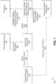
FIG. 1 is an interface diagram showing an AR system. -
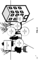
FIG. 2 is an example AR display with AR information obstructing a user's view. -
FIG. 3 is an example AR display with AR information displayed outside an activity zone. -
FIG. 4 is an example AR display with an activity zone surrounding a person in a user's field of view. -
FIG. 5 is an example AR display with AR information displayed along the top and right side of an AR display. -
FIGs. 6A and 6B are perspective view schematic diagrams for the placement of AR information at two moments in time. -
FIGs. 7A and 7B are perspective view schematic diagrams for the placement of AR information at two moments in time when a user changes direction of motion. -
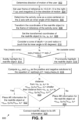
FIG. 8 is a flowchart showing an exemplary embodiment for determining a screen location for displaying AR information related to a real-world object. -
FIG. 9 is a message sequence diagram for messages communicated between processes and devices for displaying AR information for an exemplary embodiment. -
FIG. 10 is a plan view schematic diagram of a two-dimensional coordinate system showing a user and an activity zone. -
FIG. 11 is a perspective view schematic diagram of a three-dimensional coordinate system showing a user and a real-world object. -
FIG. 12 is a perspective view schematic diagram of a three-dimensional coordinate system showing a user and two real-world objects. -
FIG. 13 is a plan view schematic diagram of an AR display showing two real-world objects and associated AR information. -
FIG. 14 is a plan view schematic diagram of an AR display showing two real-world objects and associated AR information, along with an activity zone and an observation zone. -
FIG. 15A depicts an example wireless transmit/receive unit (WTRU) that may be used within a communications system. -
FIG. 15B depicts an exemplary network entity that may be used within a communication system. - The entities, connections, arrangements, and the like that are depicted in-and described in connection with-the various figures are presented by way of example and not by way of limitation. As such, any and all statements or other indications as to what a particular figure "depicts," what a particular element or entity in a particular figure "is" or "has," and any and all similar statements-that may in isolation and out of context be read as absolute and therefore limiting-may only properly be read as being constructively preceded by a clause such as "In at least one embodiment...." For brevity and clarity of presentation, this implied leading clause is not repeated ad nauseum in the detailed description of the drawings.
- In exemplary embodiments described herein, augmented reality annotations are displayed at a position as not to obstruct a user's view of a determined activity zone (or region). For example, when a user is moving in a particular direction, the augmented reality annotations may be positioned so as not to obstruct the user's view in that direction of motion. For some exemplary embodiments, the user guides the direction of motion, e.g., while walking, riding a bicycle, driving a car, or riding a Segway. For such embodiments, the user's direction of gaze may continually approximate the user's direction of motion, even though the two directions may not be identical. If a user shifts his or her gaze to another direction, e.g., to read the AR information or to look at a highlighted object near the periphery, exemplary embodiments of methods or systems described herein will not cause AR information or associated graphics to move out of the way of the user's gaze. Such embodiments may have greater stability to the user by displaying information out of the way. When a user is a passenger in a train or car, though, a user's direction of gaze may be decoupled from the user's direction of motion.
- One embodiment of a method disclosed herein tracks a direction of travel of a user of an augmented reality (AR) display, identifies an object having associated AR information, determines whether the direction of travel is substantially towards the object, selects a location for display of the AR information, wherein selecting the location comprises: selecting a first location at an offset from the object while the direction of travel is substantially towards the object, and selecting a second location that at least partially obscures the object while the direction of travel is not substantially towards the object, and displays the AR information at the selected location using the AR display.
- For one or more embodiments, a method for displaying (or rendering) AR information about a real-world object in a user's view (or AR display) may comprise multiple steps: receiving real-world object data, determining a user's activity zone, highlighting a real-world object based on where the real-world object lies with respect to the activity zone, displaying a real-world object's AR information outside an activity zone, and displaying an association of the AR information with a real-world object. An AR system may receive data regarding a real-world object, along with the object's coordinates in a system's visual field and associated augmented information. For one embodiment, determining a user's activity zone may comprise determining the user's direction of motion as a straight line and determining a zone as a preset view angle centered on the user's direction of motion. For another embodiment, determining a user's activity zone may be based on a nonlinear direction of motion, such as a user walking on a curved path. Determining the user's direction of motion as a straight line may comprise predicting motion based on (as appropriate): the major dimension of movement of the user, the orientation of the user's body (including chest and feet), and the direction in which the user leans. For one embodiment, highlighting a real-world object based on where a real-world object lies with respect to an activity zone may comprise displaying subtle highlighting (such as a silhouette or a soft glow overlay) for the object if the object is displayed within the activity zone and displaying prominent (or strong) highlighting (such as hatching) for the object if the object is displayed outside the activity zone. For one embodiment, a real-world object's AR information may be displayed at a point along the outside periphery of the activity zone closest to the object. For one embodiment, displaying an association of AR information with a real-world object may comprise highlighting the AR information in a way that matches the highlighting of the real-world object and displaying a line linking the AR information with the real-world object, which may comprise subtle lines for within-zone objects and prominent lines for outside-zone objects.
- Prominent highlighting may differ from subtle highlighting in one or more of various different properties. For example, as compared to subtle highlighting, prominent highlighting may have one or more of a greater opacity, greater line thickness, greater brightness, greater color saturation, or other properties indicative of prominence.
-
FIG. 1 shows a process interface diagram of anAR system 100. Ascene sensor 150, such as a camera or LIDAR system, captures image data. For one embodiment,scene sensors 150 measure information about ascene 162, e.g., as a point cloud, and communicate such scene information to anActivity Zone Determiner 154 and to augmented reality applications. User-specific sensors 152 may provide information about a user, such as orientation of a user's chest or the angle of a user's shoes. Augmented Reality applications 160 (or apps) or services external to systems and methods described herein may receive data related to identified real-world objects along with information to display in an augmented manner. AnAR application 160 may communicate identified objects andaugmented information 172 to an augmented reality and object locator andinformation placer 158. AnActivity Zone Determiner 154 may determine anactivity zone 168 for a scene and communicate information used to describe the activity zone to an augmented reality object locator andinformation placer 158. A user-specific sensor 152 may measure user-specific data and communicate user activity information 166 to anActivity Zone Determiner 154. AnActivity Zone Determiner 154 may use data from user-specific sensors 152 to determine a user'sactivity zone 168 comprising of the region of the visual field that may be relevant or most relevant to a user's activity. For one embodiment, the activity zone may be determined from the user's direction of motion by estimating where the user may arrive within a small duration (such as five seconds) with a diameter corresponding to an inner part of the visual field. For one embodiment, such an inner part of the visual field may be a "near peripheral" area that is a wedge-shaped area centered on an axis of motion with angles of 30° clockwise and counterclockwise from a center direction directly in front on a user's eye. For example, if a user is walking, anActivity Zone Determiner 154 may determine a zone as the part of the visual field that includes where the user may be within ten or fewer steps. An Augmented Reality Object Locator andInformation Placer 158 may locate identified objects with respect to anactivity zone 168 and determine subtle orprominent highlights 170, as appropriate. An Augmented Reality Object Locator andInformation Placer 158 may determine locations outside anactivity zone 168 foraugmented information 170 associated with these objects that minimizes the distance between theaugmented information 170 and the associated objects and may determine a display style for aconnection 170 between an identified object and an identified object's associatedaugmented information 170. For one embodiment, object highlight data, augmented information, and connectionline display data 170 is communicated to an AR display 156 (or display). AnAR display 156 may display augmented information to a user. For one embodiment, augmented information, connection line display data, and object highlight data may be used to display data to a user. - For some embodiments, an AR device comprises the components illustrated in
FIG. 1 : scene sensor,Activity Zone Determiner 154, user-specific sensor(s), augmented reality application(s), Augmented Reality Object Locator andInformation Placer 158, and anAR display 156. For some embodiments, for example,scene sensors 150 may use a camera integrated into a smart phone. Other scene and user-specific sensors may be integrated into a headset or AR glasses. For some embodiments, one or more scene sensors may be mounted to the top of a headset, along with user-specific sensors. For some embodiments, mounted to or otherwise coupled with a headset may be a processor for running software that implements anActivity Zone Determiner 154, an Augmented Reality Object Locator andInformation Placer 158, and one ormore AR applications 160. User-specific sensors may measure heartrate, walking or running speed, temperature, and these sensors may be integrated into a smart phone or other AR device. For some embodiments, anActivity Zone Determiner 154 and an Augmented Reality Object Locator andInformation Placer 158 may be processes running on a processor within an AR device. For some embodiments, anAR display 156 may be a screen on a smart phone. For some embodiments, anAR display 156 may be a see-through display device, such as an AR-enabled vehicle windshield or AR optical see-through glasses or headset. For some embodiments,scene sensor data scene sensor 150 external to an AR device and communicated to an AR device. For some embodiments, user-specific sensor data is measured by devices external to an AR device and communicated to an AR device. For some embodiments,augmented reality applications 160 running on a device external to an AR device may communicate identified objects and augmented information to an AR device. For some embodiments, an AR device comprises anActivity Zone Determiner 154 and an Augmented Reality Object Locator andInformation Placer 158, whileAR applications 160, scene sensor(s) 150, user-specific sensor(s) 152, and anAR display 156 are external. -
FIG. 2 shows anexample display 200 within an AR device not using systems and methods described herein.AR information -
FIG. 3 shows anexample display 300 within an AR device using systems and methods described herein. For one embodiment, real-world objects 316, 318, 320 are highlighted either subtly or prominently based on whether an object is inside or outside an activity zone. For one embodiment shown inFIG. 3 , the big circle is the periphery of anactivity zone 314.AR information activity zone 314. -
FIG. 4 shows anexample AR display 400 with an activity zone surrounding aperson 402 in a user's field of view. AR information 404 regarding the person's gender, height, and weight are displayed to the left of the person.AR information -
FIG. 5 shows another example AR display. For this example, a user is walking around a city center. AR information is displayed along the top and right sides of the AR display. For this example, icons are displayed showing the locations of the nearest Laduree bakery, McDonald's fast food restaurants, Starbuck's coffee, and taxi stand, along with distances to each of these locations underneath each icon. - For some embodiments, an AR display is an optical see-through device. For some embodiments, an AR display is provided on a windshield of a vehicle. For some embodiments, an AR display is embedded in glasses or goggles. For some embodiments, an AR display renders all objects and graphics seen on a screen. For some embodiments, an AR display renders graphical overlays on top of optically-seen real-world objects.
- For
FIGs. 2 and3 , some embodiments may display the example white boxes, circles, and lines as graphical overlays on top of the optically-seen real-world objects represented by the black and white photograph. Similarly, forFIG. 4 , some embodiments may display the text and white outline of the activity zone displayed around the person in the foreground as graphical overlays on top of the optically-seen real-world objects represented by the black and white photograph. ForFIG. 5 , oneembodiment 500 may display abakery icon 502, two fastfood restaurant icons coffee shop icon 508, and ataxi stand icon 510, along withdistances FIGs. 2 to 5 may be rendered by an AR display. -
FIGs. 6A and 6B are perspective schematic diagrams 600, 650 for the placement ofAR information world object 602, shown as a cube inFIG. 6A .AR information 604 related to the object is displayed to the left of theobject 602 and the user's direction ofmotion 606. At time t 2, the user has substantially stopped moving 656 towards theobject 652, as shown inFIG. 6B .AR information 654 related to theobject 652 is displayed towards the top of theobject 652. For some embodiments, responsive to a determination that the user has substantially stopped moving in the direction of travel, AR information associated with a real-world object may be rendered on an AR display at a location on the AR display that at least partially obscures the real-world object. -
FIGs. 7A and 7B are perspective schematic diagrams 700, 750 for the placement ofAR information world object 702, shown as a cube inFIG. 7A .AR information 704 related to theobject 702 is displayed to the left of the object and the user's direction ofmotion 706. At time t 2, the user turns to the left and starts walking to the left of theobject 752, as shown inFIG. 7B .AR information 754 related to theobject 752 is displayed towards the top of theobject 752 and to the right of the user's direction ofmotion 756. -
FIG. 8 is aflowchart 800 for an exemplary embodiment for determining a screen location for displaying AR information related to a real-world object. For one embodiment, the direction of motion of the user is determined 802. A user frame of reference to location <0,0,0> within a coordinate system for the user's motion may be set 804, where for one embodiment, positive x-axis values are to the right, positive y-axis values are up, and negative z-axis values are in the direction of the user's motion. For one embodiment, an activity zone is determined 806 as a cone (or conical region) centered on the z-axis with an inner angle of 60 degrees centered on the z-axis and the point of the cone centered on the user. For one embodiment, the coordinates of a real-world object are transformed 808 to the coordinate system for the frame of reference of the activity zone. For one embodiment, the real-world object's transformed coordinates are set 808 to < x 0, y 0, z 0 >. For one embodiment, the activity zone is further determined 810 to be a cone of depth z 0 with a radius rc such that the cone's inner angle is 60 degrees. For one embodiment, a process determines 812 if x 0 2 + y 0 2 < rc 2 . If x 0 2 + y 0 2 < rc 2 , the real-world object is inside the activity zone's cone and subtle highlighting is added 814 to the real-world object on the AR display. Otherwise (for the same embodiment), the real-world object is outside the activity zone's cone and prominent highlighting is added 816 to the real-world object on the AR display. - For some embodiments, subtle highlighting comprises displaying a non-clear transparency on top of the real-world object. For some embodiments, subtle highlighting comprises displaying transparent colors with an intensity level less than a predetermined threshold. For some embodiments, subtle highlighting comprises displaying a transparent color associated with a highlighter, such as light pink, light orange, light yellow, light green, light blue, or light purple. For some embodiments, subtle highlighting comprises displaying a thin-line graphic around the real-world object or displaying a thin line connecting the real-world object to augmented information.
- For some embodiments, prominent highlighting comprises displaying an opaque color on top of the real-world object. For some embodiments, prominent highlighting comprises displaying opaque colors with an intensity level greater than a predetermined threshold. For some embodiments, prominent highlighting comprises displaying an opaque color, such as solid red, solid orange, solid yellow, solid green, solid blue, or solid purple. For some embodiments, prominent highlighting comprises displaying a thick-line graphic around the real-world object or displaying a thick line connecting the real-world object to augmented information.
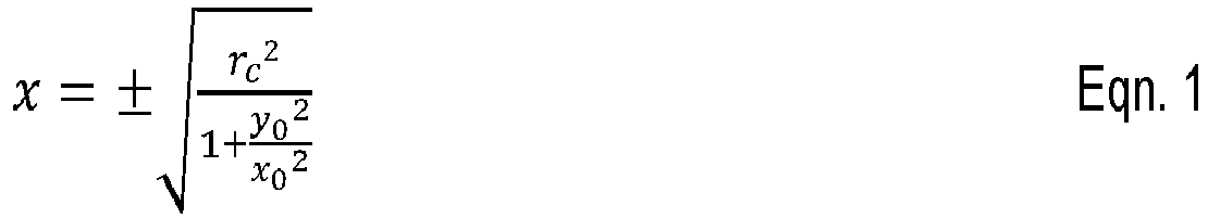
- For one embodiment, xpos and xneg are calculated 818 as the two solutions to Eqn. 1.


-
FIG. 9 shows a message sequence diagram 900 for messages communicated between processes and devices for displaying AR information for an exemplary embodiment. A location is listed above each device or process for an exemplary embodiment. AScene Sensor 904 transmits 914, 916 scene data (such as point cloud) to anActivity Zone Determiner 906 and to an AR Application (which may be an information service). AUser Sensor 910 may also transmit 918 user information to anActivity Zone Determiner 906. For one embodiment, anActivity Zone Determiner 906 determines 920 an activity zone and transmits 922 a message describing the activity zone to an AR Object Locator andInformation Placer 908. An AR Object Locator andInformation Placer 908 also may receive 924 a message from anAR Application 912 with location data for real-world objects in a scene and augmented information about those real-world objects. An AR Object Locator andInformation Placer 908 determines 926 a location of the real-world object with respect to the activity zone and for one embodiment, generates 928 scene data that may be used to display augmented information on the periphery of an activity zone. The AR Object Locator andInformation Placer 908 may send 930 a message to anAR Display 902 with scene data augmented with AR information. -
FIG. 10 shows a plan view schematic 1000 for a user 1008 and anactivity zone 1004. For this example, real-world objects sample activity zone 1004 is shown as three-dimensional oval centered on the direction of activity (or travel). For this embodiment, aninner angle 1006 of 60 degrees is shown for a cone associated with theactivity zone 1004. For this embodiment, the cone's apex is centered upon the user 1008. - For an exemplary embodiment, an
activity zone 1004 is determined using a user's chest and foot orientation based on sensor readings located on a user's body. Another embodiment uses camera image data in the infrastructure surrounding the user. One embodiment uses one or more motion sensors, such as a GPS, a compass, an accelerometer, or a gyroscope, on a user's device to calculate a main direction of travel. For one embodiment, if an accelerometer or gyroscope is used, a GPS or other location device may be used to calculate a main direction of travel. For one embodiment, a compass may be used to determine a main direction of travel. For one embodiment, two or more GPS readings may be used to determine a main direction of travel. An example of techniques that may be used to determine a user's direction of travel include those described in Gabor Paller, Motion Recognition with Android Devices, SFONGE LTD. (Oct. 7, 2011), http://www.slideshare.net/paller/motion-recognition-with-android-devices (see slide 33). - For some embodiments, an
activity zone 1004 is calculated based on a direction of travel. For some embodiments, an activity zone'scone 1014 has an opening angle is 60 degrees and whose apex is at the center of a user's device (alternatively, the center may be at the user's eyes or the device's camera) and which is centered about the ray corresponding to the user's direction of motion. The height (in math terminology), which is the depth in the present setting, of the cone1014 corresponds to how far the user may see. For some embodiments, there is acone 1014 for each height (e.g., one cone for 3 feet and another cone for 3.1 feet). Some real-world objects project inside and some do not. -
FIG. 11 shows a three-dimensional coordinatesystem 1100 with a frame of reference for a user 1102 with an origin aligned with the user 1102 and the z-axis along the user's direction of motion. For some embodiments, coordinates for anactivity zone 1108 and coordinates received for a real-world object 1106 may be used with geometric equations to determine whether a real-world object 1106 is inside or outside anactivity zone 1108. For one embodiment, the labeling of x, y, and z coordinates follow the Android convention, which are described in Freescale Semiconductor's Application Note 4317 found at http://cache.freescale.com/files/sensors/doc/app_note/AN4317.pdf (see page 2,FIG. 1 ). For the example Android coordinate convention, the screen of the device is perpendicular to ground and facing the user. The x-axis is to the right; the y-axis is toward the sky; and the z-axis is parallel to the ground and toward the user. Points behind the screen have negative z-axis values. Some embodiments have the origin at the bottom left of the screen. For an exemplary embodiment used herein, the origin is in the middle of the screen. The device's screen may be small relative to the real world in target applications, so the error between these two embodiments may not be significant. - For some embodiments, scene data is received, which may be a point cloud. The scene data may correspond to what a user sees naturally in the real-world environment. For an object in a scene, a ray may exist that goes from the coordinate system's origin to the object. For objects with a nonzero extent, multiple rays may exist that go from the origin to the different sides of the object. For some embodiments, the coordinate system may be transformed from the received scene data (which may be a point cloud) to a coordinate system aligned with the user direction of motion, which may have negative z-axis values in the direction of motion. The angle between an object's ray and a z-axis aligned with the user's direction of motion may be calculated. If this calculated angle is less than half the opening angle of the cone, the real-world object may be determined to lie inside the activity zone. Otherwise, for this embodiment, the real-world object may be determined to lie outside the activity zone. Some embodiments may make these determinations based on calculations using a real-world object's coordinates without calculating the angle between the two rays described above.
- For one embodiment shown in
FIG. 11 , anactivity zone 1108 has at least one cone with an apex at the origin and a base centered on the Z axis. For one embodiment, the radius/height 1104 equals the tangent of 30 degrees or 0.577. That is,
- One embodiment has a real-world object at coordinates < x 0 ,y 0,z 0 >. This embodiment may have a cone that has the same depth as the object (zc = z 0). For this example, the object is within the user's activity zone if x 0 2 + y 0 2 ≤ rc 2. If the object is within the user's activity zone, the AR information corresponding to the object may be displayed as a point along the outside periphery of the activity zone closest to the object. For one embodiment, augmented information is displayed at a point on the periphery of the activity zone closest to the real-world object. For one embodiment, this point is determined through use of the Pythagorean Theorem and geometric calculation. A line linking the real-world object to the associated augmented information may be displayed between the two items.
-
FIG. 12 is a three-dimensional coordinatesystem 1200 centered on a user 1202 showing a real-world object 1206 and placement of augmented information. For one embodiment, a real-world object 1206 is at < x 0, y 0, z 0 > and the center of a cone's base is at < 0, 0,z 0 >.FIG. 12 shows oneobject 1214 located inside and one object 1206 located outside anexample activity zone 1208. For this example, both real-world objects and the cone's base are in the same plane, located at z = z0, and the equations that follow are for the x-axis and y-axis values. Theradius 1204 of the cone's base is rc. For this example, the slope s of the line from the object to the center of the base of the cone is
points 


- For this example, the equations may be used to calculate two solutions, which are the positive (xpos ) and negative (xneg ) values of x that lie on the circle and the corresponding values of y, which may be positive or negative depending upon the slope. For this example, the equation solutions are < xpos , (s)(xpos ) > and < xneg, (s)(xneg ) >. Substituting


-
FIG. 13 is a plan view schematic 1300 (or bird's eye view) of a user 1306 and two real-world objects user 1308 to indicate the periphery of the user'sactivity zone 1304. For another embodiment, a graphic is not displayed in front of a user 1306 to indicate the periphery of the user'sactivity zone 1304. For this example, the user'sgaze 1302 is aligned with the user'sactivity zone 1304. For exemplary embodiments, augmented information, except for subtle highlights and linkages to AR information displayed along the periphery of theactivity zone 1304, is not displayed within theactivity zone 1304.AR information FIG. 13 ,AR information gaze direction 1302. Oneobject 1308 located within anactivity zone 1304 and within a user'sgaze direction 1302 is highlighted subtly, while anotherobject 1312 located outside anactivity zone 1304 and outside a user'sgaze direction 1302 is highlighted prominently. -
FIG. 14 is a schematic plan view 1400 (or bird's eye view) of a user 1406 and two real-world objects activity zone 1404 is displayed aligned with a direction of activity 1402 in front of the user 1406, but the user'sgaze 1416 is off center and to the right. The user 1406 may be looking at a highlighted object 1412 (as shown inFIG. 14 ),AR information 1414 for anobject 1412, or an object without highlighting. Similar to the embodiment shown inFIG. 13 , theactivity zone 1404 remains clear of augmented information except for subtle highlights and linkages to AR information on the periphery of the activity zone.AR information remote objects activity zone 1404. Theobservation zone 1418 is the part of the AR display where the user 1406 is looking that is outside of theactivity zone 1404. Theobservation zone 1418 may be cluttered with AR information while theactivity zone 1404 remains free of clutter. As shown in the embodiment ofFIG. 14 , theactivity zone 1404 remains stable. For this embodiment, if a user'sgaze 1416 shifts,AR information 1414 shown within the scene may not move (or "jump around"). For this embodiment, theactivity zone 1404 may become peripheral to the user's vision but theactivity zone 1404 continues to the clear. For one embodiment, if the user 1406 looks atAR information 1414 outside anactivity zone 1404, thatAR information 1414 does not move (or "bounce away"), which would occur ifAR information 1414 always was displayed outside the user's direction ofgaze 1416. The embodiment shown inFIG. 14 uses both anactivity zone 1404 and anobservation zone 1418 in determining where to display AR information for a seamless AR user experience. - For one embodiment, an activity zone is determined to be a cone-shaped area with an apex centered on a user's (or viewer's) head with an opening angle of 60 degrees and a z-axis plane aligned with a displayed object located at a maximum distance from the user in the direction of travel (or as far as the user is able to see in the direction of travel). For one embodiment, no visual demarcation is displayed for the activity zone, unlike
FIG. 3 , which shows the activity zone as a thick circle. For some embodiments, a graphic may be rendered on an AR display that indicates a periphery of an activity zone. For one embodiment, an activity zone may be determined to be a distorted (or non-symmetrical) shape (instead of a symmetrical, conical, or circular shape) based on a user's activity. For example, an activity zone may be wider than the height if a user's activity is focused on the lower part of the scene. For one embodiment, an activity zone is a rectangle. For one embodiment, an activity zone is a plurality of disconnected shapes. For one embodiment, an activity zone is a three-dimensional shape. For one embodiment, determination of a user's activity zone is based not on a two-dimensional model but a three-dimensional model incorporating depth, where the activity zone may be a conical shape or three-dimensional part of the scene. For one embodiment, determination of a user's activity zone may be based, not on the user's direction of motion, but on the salience of a part of the scene, such as, what objects appear in what part of the scene. For one embodiment, a user's activity zone may have one or more salient objects based on the user's activity. For one embodiment, an activity zone is not a contiguous region (or is a plurality of disconnected shapes). For one embodiment with real-world objects outside of an activity zone, associated AR information is displayed (or placed) near the object along with a marker at the periphery of the activity zone that indicates some AR information is available if the user looks toward the real-world object. For some embodiments, additional AR information may be displayed if the user looks toward current AR information. - For an example consumer use case, John uses some AR applications as he walks through New York City. His activity is recognized as walking and an associated activity zone is determined to be the path in front of him up to about 3 feet ahead. John is able to view his walking path because AR information received from his AR applications is not displayed in his direction of travel. For example, if John sees interesting people, such as celebrities, some AR apps display information about those people. This information is displayed outside the activity zone.
- For another consumer user case, John runs into Mary while walking through Times Square. They have an animated conversation. His activity is determined to be chatting with Mary, and the associated activity zone changes to Mary's body frame (which may be a silhouette slightly larger than Mary). As John stands and chats with Mary, he looks left and right from time to time. Different real-world objects may come within view either within his activity zone (e.g., next to Mary's ear) or outside his activity zone (e.g., to the right and down the street). The AR information for these objects is placed outside John's activity zone. If John turns to read this information or to examine a real-world object in some detail, the AR information may change but none of the AR information obstructs his view of Mary.
- A wireless transmit/receive unit (WTRU) may be used as a AR display device in embodiments described herein. The AR device shown in
FIGs. 15A to 15B may be used to retrieve AR information. -
FIG. 15A is a system diagram of anexample WTRU 102. As shown inFIG. 15A , theWTRU 102 may include aprocessor 118, atransceiver 120, a transmit/receiveelement 122, a speaker/microphone 124, akeypad 126, a display/touchpad 128, anon-removable memory 130, aremovable memory 132, apower source 134, a global positioning system (GPS)chipset 136, andother peripherals 138. Thetransceiver 120 may be implemented as a component of decoder logic 119. For example, thetransceiver 120 and decoder logic 119 may be implemented on a single LTE or LTE-A chip. The decoder logic may include a processor operative to perform instructions stored in a non-transitory computer-readable medium. As an alternative, or in addition, the decoder logic may be implemented using custom and/or programmable digital logic circuitry. - It will be appreciated that the
WTRU 102 may include any sub-combination of the foregoing elements while remaining consistent with an embodiment. Also, embodiments contemplate that base stations and/or the nodes that base stations may represent, such as but not limited to transceiver station (BTS), a Node-B, a site controller, an access point (AP), a home node-B, an evolved home node-B (eNodeB), a home evolved node-B (HeNB), a home evolved node-B gateway, and proxy nodes, among others, may include some or all of the elements depicted inFIG. 15A and described herein. - The
processor 118 may be a general purpose processor, a special purpose processor, a conventional processor, a digital signal processor (DSP), a plurality of microprocessors, one or more microprocessors in association with a DSP core, a controller, a microcontroller, Application Specific Integrated Circuits (ASICs), Field Programmable Gate Array (FPGAs) circuits, any other type of integrated circuit (IC), a state machine, and the like. Theprocessor 118 may perform signal coding, data processing, power control, input/output processing, and/or any other functionality that enables theWTRU 102 to operate in a wireless environment. Theprocessor 118 may be coupled to thetransceiver 120, which may be coupled to the transmit/receiveelement 122. WhileFIG. 15A depicts theprocessor 118 and thetransceiver 120 as separate components, it will be appreciated that theprocessor 118 and thetransceiver 120 may be integrated together in an electronic package or chip. - The transmit/receive
element 122 may be configured to transmit signals to, or receive signals from, a base station over the air interface 116. For example, in one embodiment, the transmit/receiveelement 122 may be an antenna configured to transmit and/or receive RF signals. In another embodiment, the transmit/receiveelement 122 may be an emitter/detector configured to transmit and/or receive IR, UV, or visible light signals, as examples. In yet another embodiment, the transmit/receiveelement 122 may be configured to transmit and receive both RF and light signals. It will be appreciated that the transmit/receiveelement 122 may be configured to transmit and/or receive any combination of wireless signals. - In addition, although the transmit/receive
element 122 is depicted inFIG. 15A as a single element, theWTRU 102 may include any number of transmit/receiveelements 122. More specifically, theWTRU 102 may employ MIMO technology. Thus, in one embodiment, theWTRU 102 may include two or more transmit/receive elements 122 (e.g., multiple antennas) for transmitting and receiving wireless signals over the air interface 116. - The
transceiver 120 may be configured to modulate the signals that are to be transmitted by the transmit/receiveelement 122 and to demodulate the signals that are received by the transmit/receiveelement 122. As noted above, theWTRU 102 may have multi-mode capabilities. Thus, thetransceiver 120 may include multiple transceivers for enabling theWTRU 102 to communicate via multiple RATs, such as UTRA and IEEE 802.11, as examples. - The
processor 118 of theWTRU 102 may be coupled to, and may receive user input data from, the speaker/microphone 124, thekeypad 126, and/or the display/touchpad 128 (e.g., a liquid crystal display (LCD) display unit or organic light-emitting diode (OLED) display unit). Theprocessor 118 may also output user data to the speaker/microphone 124, thekeypad 126, and/or the display/touchpad 128. In addition, theprocessor 118 may access information from, and store data in, any type of suitable memory, such as thenon-removable memory 130 and/or theremovable memory 132. Thenon-removable memory 130 may include random-access memory (RAM), read-only memory (ROM), a hard disk, or any other type of memory storage device. Theremovable memory 132 may include a subscriber identity module (SIM) card, a memory stick, a secure digital (SD) memory card, and the like. In other embodiments, theprocessor 118 may access information from, and store data in, memory that is not physically located on theWTRU 102, such as on a server or a home computer (not shown). - The
processor 118 may receive power from thepower source 134, and may be configured to distribute and/or control the power to the other components in theWTRU 102. Thepower source 134 may be any suitable device for powering theWTRU 102. As examples, thepower source 134 may include one or more dry cell batteries (e.g., nickel-cadmium (NiCd), nickel-zinc (NiZn), nickel metal hydride (NiMH), lithiumion (Li-ion), and the like), solar cells, fuel cells, and the like. - The
processor 118 may also be coupled to theGPS chipset 136, which may be configured to provide location information (e.g., longitude and latitude) regarding the current location of theWTRU 102. In addition to, or in lieu of, the information from theGPS chipset 136, theWTRU 102 may receive location information over the air interface 116 from a base station and/or determine its location based on the timing of the signals being received from two or more nearby base stations. It will be appreciated that theWTRU 102 may acquire location information by way of any suitable location-determination method while remaining consistent with an embodiment. - The
processor 118 may further be coupled toother peripherals 138, which may include one or more software and/or hardware modules that provide additional features, functionality and/or wired or wireless connectivity. For example, theperipherals 138 may include an accelerometer, an e-compass, a satellite transceiver, a digital camera (for photographs or video), a universal serial bus (USB) port, a vibration device, a television transceiver, a hands free headset, a Bluetooth® module, a frequency modulated (FM) radio unit, a digital music player, a media player, a video game player module, an Internet browser, and the like. -
FIG. 15B depicts anexample network entity 190 that may be used within thecommunication system 100 ofFIG. 15A . As depicted inFIG. 15B ,network entity 190 includes acommunication interface 192, aprocessor 194, andnon-transitory data storage 196, all of which are communicatively linked by a bus, network, orother communication path 198. -
Communication interface 192 may include one or more wired communication interfaces and/or one or more wireless-communication interfaces. With respect to wired communication,communication interface 192 may include one or more interfaces such as Ethernet interfaces, as an example. With respect to wireless communication,communication interface 192 may include components such as one or more antennae, one or more transceivers/chipsets designed and configured for one or more types of wireless (e.g., LTE) communication, and/or any other components deemed suitable by those of skill in the relevant art. And further with respect to wireless communication,communication interface 192 may be equipped at a scale and with a configuration appropriate for acting on the network side-as opposed to the client side-of wireless communications (e.g., LTE communications, Wi-Fi communications, and the like). Thus,communication interface 192 may include the appropriate equipment and circuitry (which may include multiple transceivers) for serving multiple mobile stations, UEs, or other access terminals in a coverage area. -
Processor 194 may include one or more processors of any type deemed suitable by those of skill in the relevant art, some examples including a general-purpose microprocessor and a dedicated DSP. -
Data storage 196 may take the form of any non-transitory computer-readable medium or combination of such media, some examples including flash memory, read-only memory (ROM), and random-access memory (RAM) to name but a few, as any one or more types of non-transitory data storage deemed suitable by those of skill in the relevant art may be used. As depicted inFIG. 15B ,data storage 196 containsprogram instructions 197 executable byprocessor 194 for carrying out various combinations of the various network-entity functions described herein. - In some embodiments, the network-entity functions described herein are carried out by a network entity having a structure similar to that of
network entity 190 ofFIG. 15B . In some embodiments, one or more of such functions are carried out by a set of multiple network entities in combination, where each network entity has a structure similar to that ofnetwork entity 190 ofFIG. 15B . - Note that various hardware elements of one or more of the described embodiments are referred to as "modules" that carry out (i.e., perform, execute, and the like) various functions that are described herein in connection with the respective modules. As used herein, a module includes hardware (e.g., one or more processors, one or more microprocessors, one or more microcontrollers, one or more microchips, one or more application-specific integrated circuits (ASICs), one or more field programmable gate arrays (FPGAs), one or more memory devices) deemed suitable by those of skill in the relevant art for a given implementation. Each described module may also include instructions executable for carrying out the one or more functions described as being carried out by the respective module, and those instructions may take the form of or include hardware (or hardwired) instructions, firmware instructions, software instructions, and/or the like, and may be stored in any suitable non-transitory computer-readable medium or media, such as commonly referred to as RAM or ROM.
- Although features and elements are described above in particular combinations, one of ordinary skill in the art will appreciate that each feature or element may be used alone or in any combination with the other features and elements. In addition, the methods described herein may be implemented in a computer program, software, or firmware incorporated in a computer-readable medium for execution by a computer or processor. Examples of computer-readable storage media include, but are not limited to, a read only memory (ROM), a random access memory (RAM), a register, cache memory, semiconductor memory devices, magnetic media such as internal hard disks and removable disks, magneto-optical media, and optical media such as CD-ROM disks, and digital versatile disks (DVDs). A processor in association with software may be used to implement a radio frequency transceiver for use in a WTRU, UE, terminal, base station, RNC, or any host computer.
- Example 1 is a method comprising: tracking a direction of travel of a user of an augmented reality (AR) display; identifying an object having associated AR information; determining whether the direction of travel is substantially towards the object; selecting a location for display of the AR information, wherein selecting the location comprises: selecting a first location at an offset from the object while the direction of travel is substantially towards the object; and selecting a second location that at least partially obscures the object while the direction of travel is not substantially towards the object; and displaying the AR information at the selected location using the AR display. Example 2 is the method of example 1, wherein determining whether the direction of travel is substantially towards the object comprises determining whether the object is within an activity zone with a conical shape substantially centered on the direction of travel. Example 3 is the method of example 2, wherein the first location is a location outside the activity zone. Example 4 is the method of example 1, wherein the AR display is an AR headset, and wherein identifying the object is performed using a scene-sensing camera on the headset. Example 5 is the method of example 1, further comprising: rendering a subtle highlight on the object while the direction of travel is substantially towards the object; and rendering a prominent highlight on the object while the direction of travel is not substantially towards the object. Example 6 is the method of example 1, further comprising: identifying a second object having associated second AR information; determining whether the direction of travel is substantially towards the second object; selecting a location for display of the second AR information, wherein selecting the location comprises: selecting a third location at an offset from the second object while the direction of travel is substantially towards the object; and selecting a fourth location that at least partially obscures the second object while the direction of travel is not substantially towards the second object; and displaying the second AR information at the selected location using the AR display, rendering a second soft glow overlay on the second object while the direction of travel is substantially towards the second object; and rendering a second strong highlight on the second object while the direction of travel is not substantially towards the second object. Example 7 is the method of example 1, further comprising: calculating one or more relevance scores for one or more correlating non-overlapping regions within visual field of view of the user; determining an activity zone as the region within visual field of view of the user with the highest relevance score for the user; and rendering on the display a line connecting the first object with the first AR information with a soft glow overlay for the portion of the line inside the activity zone and a strong highlight for the portion of the line outside the activity zone. Example 8 is the method of example 7, further comprising: responsive to a determination that the first object is inside the activity zone, rendering the line with a soft glow overlay; and responsive to a determination that the first object is outside the activity zone, rendering the line with a strong highlight. Example 9 is the method of examples 7 or 8, wherein the activity zone is a shape that is an outline of a person. Example 10 is the method of examples 7 or 8, wherein the activity zone is a rectangle.
- Example 11 is the method of examples 7 or 8, wherein the activity zone is a three-dimensional shape. Example 12 is a method comprising: tracking a direction of travel of a user of an augmented reality (AR) display; determining that the direction of travel is substantially towards a point; selecting a location for display of AR information, wherein selecting the location comprises: selecting a first location at an offset from the point while the direction of travel is substantially towards the point; and selecting a second location that at least partially obscures the point while the direction of travel is not substantially towards the point; and displaying the AR information at the selected location using the AR display. Example 13 is the method of example 12, wherein determining whether the direction of travel is substantially towards the point comprises determining whether the point is within an activity zone with a conical shape substantially centered on the direction of travel. Example 14 is the method of example 12, further comprising: identifying an object having associated AR information; determining whether the direction of travel is substantially towards the object; rendering a soft glow overlay on the object while the direction of travel is substantially towards the object; and rendering a strong highlight on the object while the direction of travel is not substantially towards the object. Example 15 is a system comprising: a display; a processor; and a non-transitory computer-readable medium storing instructions that are operative, when executed on the processor, to perform the functions of: tracking a direction of travel of a user of an augmented reality (AR) display; identifying an object having associated AR information; determining whether the direction of travel is substantially towards the object; selecting a location for display of the AR information, wherein selecting the location comprises: selecting a first location at an offset from the object while the direction of travel is substantially towards the object; and selecting a second location that at least partially obscures the object while the direction of travel is not substantially towards the object; and displaying the AR information at the selected location using the AR display.
Claims (15)
- A method comprising:using at least one sensor (150, 152) of an augmented reality, AR, capable device (100), determining an activity zone (154, 806,906), the activity zone (168, 314,922, 1004, 1108, 1208, 1304, 1404) being defined by a shape centered on a direction of activity of a user of the AR capable device;selecting a position (108, 822, 824, 928) for an AR annotation of a real-world object in the activity zone, wherein the selecting of the position is performed such that the AR annotation does not obscure the activity zone; anddisplaying the AR annotation on the AR capable device at the selected position.
- The method of claim 1, wherein the shape is a 2D shape.
- The method of claim 1, wherein the shape is a 3D shape.
- The method of claim 1, wherein the direction of activity is a direction of motion of the user.
- The method of claim 4, further comprising:using the least one sensor, determining that the direction of motion of the user has changed;updating the activity zone according to the changed direction of motion; andupdating the position of the AR annotation such that the AR annotation does not obscure the activity zone.
- The method of claim 1, wherein the determination of the activity zone is based on a salient object associated with an activity of the user.
- The method of claim 1, wherein selecting a position for an AR annotation for the real-world object in the activity zone comprises placing the AR annotation at a location along a periphery of the activity zone closest to the location of the real-world object.
- The method of claim 1, further comprising displaying a graphic connection between the AR annotation and the real-world object.
- The method of claim 1, wherein the activity zone is a circle, an oval, a rectangle, or a cone.
- The method of claim 1, further comprising displaying a graphical indication of the extent of the activity zone.
- A system comprising one or more processors configured to perform at least:using at least one sensor (150, 152) of an augmented reality, AR, capable device (100), determining an activity zone (154, 806,906), the activity zone (168, 314,922, 1004, 1108, 1208, 1304, 1404) being defined by a shape centered on a direction of activity of a user of the AR capable device;selecting a position (108, 822, 824, 928) for an AR annotation of a real-world object in the activity zone, wherein the selecting of the position is performed such that the AR annotation does not obscure the activity zone; anddisplaying the AR annotation on the AR capable device at the selected position.
- The system of claim 11, further configured to perform:using the least one sensor, determining that the direction of motion of the user has changed;updating the activity zone according to the changed direction of motion; andupdating the position of the AR annotation such that the AR annotation does not obscure the activity zone.
- The system of claim 11, wherein the determination of the activity zone is based on a salient object associated with an activity of the user.
- The system of claim 11, wherein selecting a position for an AR annotation for the real-world object in the activity zone comprises placing the AR annotation at a location along a periphery of the activity zone closest to the location of the real-world object.
- The system of claim 11, further configured to display a graphical indication of the extent of the activity zone.
Applications Claiming Priority (3)
| Application Number | Priority Date | Filing Date | Title |
|---|---|---|---|
| US201662437455P | 2016-12-21 | 2016-12-21 | |
| EP17826644.1A EP3559786B1 (en) | 2016-12-21 | 2017-12-14 | System and method for placement of augmented reality information for users based on their activity |
| PCT/US2017/066499 WO2018118661A1 (en) | 2016-12-21 | 2017-12-14 | System and method for placement of augmented reality information for users based on their activity |
Related Parent Applications (2)
| Application Number | Title | Priority Date | Filing Date |
|---|---|---|---|
| EP17826644.1A Division-Into EP3559786B1 (en) | 2016-12-21 | 2017-12-14 | System and method for placement of augmented reality information for users based on their activity |
| EP17826644.1A Division EP3559786B1 (en) | 2016-12-21 | 2017-12-14 | System and method for placement of augmented reality information for users based on their activity |
Publications (2)
| Publication Number | Publication Date |
|---|---|
| EP4235382A2 true EP4235382A2 (en) | 2023-08-30 |
| EP4235382A3 EP4235382A3 (en) | 2023-10-11 |
Family
ID=60953959
Family Applications (2)
| Application Number | Title | Priority Date | Filing Date |
|---|---|---|---|
| EP17826644.1A Active EP3559786B1 (en) | 2016-12-21 | 2017-12-14 | System and method for placement of augmented reality information for users based on their activity |
| EP23180024.4A Pending EP4235382A3 (en) | 2016-12-21 | 2017-12-14 | System and method for placement of augmented reality information for users based on their activity |
Family Applications Before (1)
| Application Number | Title | Priority Date | Filing Date |
|---|---|---|---|
| EP17826644.1A Active EP3559786B1 (en) | 2016-12-21 | 2017-12-14 | System and method for placement of augmented reality information for users based on their activity |
Country Status (3)
| Country | Link |
|---|---|
| US (2) | US11024091B2 (en) |
| EP (2) | EP3559786B1 (en) |
| WO (1) | WO2018118661A1 (en) |
Families Citing this family (11)
| Publication number | Priority date | Publication date | Assignee | Title |
|---|---|---|---|---|
| US11417426B2 (en) | 2017-02-24 | 2022-08-16 | Masimo Corporation | System for displaying medical monitoring data |
| WO2018156809A1 (en) * | 2017-02-24 | 2018-08-30 | Masimo Corporation | Augmented reality system for displaying patient data |
| CN110809804B (en) | 2017-05-08 | 2023-10-27 | 梅西莫股份有限公司 | System for pairing a medical system with a network controller using an adapter |
| US10712899B2 (en) * | 2017-10-17 | 2020-07-14 | Microsoft Technology Licensing, Llc | Human-machine interface tethered to a user position in a three-dimensional VR or AR environment |
| US11527044B2 (en) * | 2018-06-27 | 2022-12-13 | Samsung Electronics Co., Ltd. | System and method for augmented reality |
| EP3637226B1 (en) * | 2018-10-12 | 2023-06-28 | ATOS France | Positioning of user interface objects within a 3d scene |
| US11137875B2 (en) * | 2019-02-22 | 2021-10-05 | Microsoft Technology Licensing, Llc | Mixed reality intelligent tether for dynamic attention direction |
| TWI736188B (en) | 2019-03-22 | 2021-08-11 | 宏達國際電子股份有限公司 | Augmented reality information transmission system and method |
| CN110908504B (en) * | 2019-10-10 | 2021-03-23 | 浙江大学 | Augmented reality museum collaborative interaction method and system |
| US10846534B1 (en) * | 2020-03-17 | 2020-11-24 | Capital Once Services, LLC | Systems and methods for augmented reality navigation |
| US11175791B1 (en) | 2020-09-29 | 2021-11-16 | International Business Machines Corporation | Augmented reality system for control boundary modification |
Family Cites Families (9)
| Publication number | Priority date | Publication date | Assignee | Title |
|---|---|---|---|---|
| US9041741B2 (en) | 2013-03-14 | 2015-05-26 | Qualcomm Incorporated | User interface for a head mounted display |
| KR20160016907A (en) * | 2013-05-29 | 2016-02-15 | 미쓰비시덴키 가부시키가이샤 | Information display device |
| US20150153826A1 (en) | 2013-12-01 | 2015-06-04 | Apx Labs, Llc | Systems and methods for providing a virtual menu |
| US20150277118A1 (en) | 2014-03-28 | 2015-10-01 | Osterhout Group, Inc. | Sensor dependent content position in head worn computing |
| US11030784B2 (en) * | 2014-06-03 | 2021-06-08 | Apple Inc. | Method and system for presenting a digital information related to a real object |
| US9984505B2 (en) | 2014-09-30 | 2018-05-29 | Sony Interactive Entertainment Inc. | Display of text information on a head-mounted display |
| GB2532954A (en) * | 2014-12-02 | 2016-06-08 | Ibm | Display control system for an augmented reality display system |
| US9767614B2 (en) * | 2015-03-24 | 2017-09-19 | Nokia Technologies Oy | Augmented reality |
| JP6421670B2 (en) * | 2015-03-26 | 2018-11-14 | 富士通株式会社 | Display control method, display control program, and information processing apparatus |
-
2017
- 2017-12-14 EP EP17826644.1A patent/EP3559786B1/en active Active
- 2017-12-14 US US16/466,600 patent/US11024091B2/en active Active
- 2017-12-14 WO PCT/US2017/066499 patent/WO2018118661A1/en active Search and Examination
- 2017-12-14 EP EP23180024.4A patent/EP4235382A3/en active Pending
-
2021
- 2021-04-30 US US17/245,618 patent/US11288878B2/en active Active
Non-Patent Citations (1)
| Title |
|---|
| GABOR PALLER: "Motion Recognition with Android Devices,", S L, 7 October 2011 (2011-10-07), Retrieved from the Internet <URL:http://www.slideshare.net/paller/motion-recognition-with-android-devices(seeslide33> |
Also Published As
| Publication number | Publication date |
|---|---|
| EP3559786B1 (en) | 2023-07-26 |
| US20200074740A1 (en) | 2020-03-05 |
| WO2018118661A1 (en) | 2018-06-28 |
| US11024091B2 (en) | 2021-06-01 |
| US20210248833A1 (en) | 2021-08-12 |
| EP4235382A3 (en) | 2023-10-11 |
| EP3559786A1 (en) | 2019-10-30 |
| US11288878B2 (en) | 2022-03-29 |
Similar Documents
| Publication | Publication Date | Title |
|---|---|---|
| US11288878B2 (en) | System and method for placement of augmented reality information for users based on their activity | |
| JP2022002144A (en) | System and method for augmented reality | |
| CN111126182B (en) | Lane line detection method, lane line detection device, electronic device, and storage medium | |
| US10295826B2 (en) | Shape recognition device, shape recognition program, and shape recognition method | |
| EP3151202A1 (en) | Information processing device and information processing method | |
| US9933853B2 (en) | Display control device, display control program, and display control method | |
| WO2022010732A1 (en) | Virtual private space for extended reality | |
| US20160021353A1 (en) | I/o device, i/o program, and i/o method | |
| JP7176520B2 (en) | Information processing device, information processing method and program | |
| US11699259B2 (en) | Stylized image painting | |
| US11178375B1 (en) | Input parameter based image waves | |
| CN111104893B (en) | Target detection method, target detection device, computer equipment and storage medium | |
| US11589024B2 (en) | Multi-dimensional rendering | |
| CN113016008A (en) | Machine learning inference of gravity aligned images | |
| CN113228688A (en) | Creating three-dimensional wallpaper on a computing device and user interaction with the three-dimensional wallpaper | |
| WO2017007643A1 (en) | Systems and methods for providing non-intrusive indications of obstacles | |
| US20150381970A1 (en) | Input/output device, input/output program, and input/output method | |
| CN117321632A (en) | Different depth determination using stereo vision and Phase Detection Autofocus (PDAF) | |
| US11146763B1 (en) | Artistic and other photo filter light field effects for images and videos utilizing image disparity | |
| KR20200092197A (en) | Image processing method, image processing apparatus, electronic device, computer program and computer readable recording medium for processing augmented reality image | |
| US20230060838A1 (en) | Scan-based messaging for electronic eyewear devices | |
| US20230298247A1 (en) | Sharing received objects with co-located users | |
| US20220146662A1 (en) | Information processing apparatus and information processing method | |
| KR20110107148A (en) | Apparatus of displaying geographic information in smart phone |
Legal Events
| Date | Code | Title | Description |
|---|---|---|---|
| PUAI | Public reference made under article 153(3) epc to a published international application that has entered the european phase |
Free format text: ORIGINAL CODE: 0009012 |
|
| STAA | Information on the status of an ep patent application or granted ep patent |
Free format text: STATUS: REQUEST FOR EXAMINATION WAS MADE |
|
| 17P | Request for examination filed |
Effective date: 20230619 |
|
| AC | Divisional application: reference to earlier application |
Ref document number: 3559786 Country of ref document: EP Kind code of ref document: P |
|
| AK | Designated contracting states |
Kind code of ref document: A2 Designated state(s): AL AT BE BG CH CY CZ DE DK EE ES FI FR GB GR HR HU IE IS IT LI LT LU LV MC MK MT NL NO PL PT RO RS SE SI SK SM TR |
|
| REG | Reference to a national code |
Ref country code: DE Ref legal event code: R079 Free format text: PREVIOUS MAIN CLASS: G06F0003048150 Ipc: G06F0003010000 |
|
| PUAL | Search report despatched |
Free format text: ORIGINAL CODE: 0009013 |
|
| AK | Designated contracting states |
Kind code of ref document: A3 Designated state(s): AL AT BE BG CH CY CZ DE DK EE ES FI FR GB GR HR HU IE IS IT LI LT LU LV MC MK MT NL NO PL PT RO RS SE SI SK SM TR |
|
| RIC1 | Information provided on ipc code assigned before grant |
Ipc: G02B 27/00 20060101ALI20230904BHEP Ipc: G02B 27/01 20060101ALI20230904BHEP Ipc: G06F 3/04815 20220101ALI20230904BHEP Ipc: G06F 3/01 20060101AFI20230904BHEP |