EP4235250A2 - Zweifarbige refraktive okularartige optische form mit sehr grossem sichtfeld - Google Patents
Zweifarbige refraktive okularartige optische form mit sehr grossem sichtfeld Download PDFInfo
- Publication number
- EP4235250A2 EP4235250A2 EP23173417.9A EP23173417A EP4235250A2 EP 4235250 A2 EP4235250 A2 EP 4235250A2 EP 23173417 A EP23173417 A EP 23173417A EP 4235250 A2 EP4235250 A2 EP 4235250A2
- Authority
- EP
- European Patent Office
- Prior art keywords
- infrared
- lenses
- dual
- lens
- wave infrared
- Prior art date
- Legal status (The legal status is an assumption and is not a legal conclusion. Google has not performed a legal analysis and makes no representation as to the accuracy of the status listed.)
- Granted
Links
Images


Classifications
-
- G—PHYSICS
- G02—OPTICS
- G02B—OPTICAL ELEMENTS, SYSTEMS OR APPARATUS
- G02B13/00—Optical objectives specially designed for the purposes specified below
- G02B13/14—Optical objectives specially designed for the purposes specified below for use with infrared or ultraviolet radiation
-
- G—PHYSICS
- G02—OPTICS
- G02B—OPTICAL ELEMENTS, SYSTEMS OR APPARATUS
- G02B13/00—Optical objectives specially designed for the purposes specified below
- G02B13/14—Optical objectives specially designed for the purposes specified below for use with infrared or ultraviolet radiation
- G02B13/146—Optical objectives specially designed for the purposes specified below for use with infrared or ultraviolet radiation with corrections for use in multiple wavelength bands, such as infrared and visible light, e.g. FLIR systems
-
- G—PHYSICS
- G02—OPTICS
- G02B—OPTICAL ELEMENTS, SYSTEMS OR APPARATUS
- G02B25/00—Eyepieces; Magnifying glasses
- G02B25/001—Eyepieces
-
- G—PHYSICS
- G02—OPTICS
- G02B—OPTICAL ELEMENTS, SYSTEMS OR APPARATUS
- G02B3/00—Simple or compound lenses
- G02B3/02—Simple or compound lenses with non-spherical faces
- G02B3/04—Simple or compound lenses with non-spherical faces with continuous faces that are rotationally symmetrical but deviate from a true sphere, e.g. so called "aspheric" lenses
Definitions
- An eyepiece is a type of lens system that can be attached to a variety of optical devices such as telescopes and microscopes.
- An objective lens or mirror collects light and brings it to focus creating an image.
- the eyepiece is placed near the focal point of the objective to magnify this image, with the amount of magnification generally being dependent on the focal length of the eyepiece.
- An eyepiece typically includes several lens elements.
- the entrance pupil of the eyepiece is external or located outside of the eyepiece system (i.e., on the objective or object space side of all the lens elements making up the eyepiece).
- an eyepiece is designed for optimal performance for a specific distance to this entrance pupil (i.e. with minimum aberrations for this distance).
- the distance between the entrance pupil and the first lens of the eyepiece can vary greatly depending on the design and intended application of the eyepiece.
- the entrance pupil may be several feet distant from the eyepiece; whereas in a microscope the entrance pupil may be only a few inches from the eyepiece.
- any optical system with a similar external entrance pupil can be termed eyepiece-like, and in common with classical eyepieces, such optical systems, because of the lack of symmetry about that external pupil, are known to be difficult to correct for off-axis aberrations, notably coma, astigmatism, and lateral color.
- aspects and embodiments are directed to a refractive eyepiece-type optical form, and to optical systems incorporating same.
- a dual-band refractive optical system configured for mid-wave infrared and long-wave infrared operation includes a plurality of lenses, each constructed from a material that is optically transparent in the mid-wave infrared and long-wave infrared spectral bands, arranged to receive infrared electromagnetic radiation in an operating waveband that includes at least a portion of the mid-wave infrared and at least a portion of the long-wave infrared spectral bands via a front external aperture stop and to focus the infrared electromagnetic radiation onto a rear image plane, the plurality of lenses being positioned between the front external aperture stop and rear image plane and together being configured to provide the dual-band refractive optical system with a field of view of approximately 130 degrees and an optical speed of F/2.0.
- the optical system may further include a corrector plate positioned coincident with the front aperture stop.
- the plurality of lenses consists of eight lenses.
- the eight lenses may include five positive powered lenses and three negative powered lenses.
- the material of five of the eight lenses is an optical crown in the operating waveband and wherein the material of three of the eight lenses is an optical flint in operating waveband, such that the optical system is achromatic over the operating waveband.
- the material of the five lenses is a chalcogenide glass and wherein the material of the three lenses is barium fluoride.
- the chalcogenide glass is AMTIR-1.
- the plurality of lenses includes a first lens positioned proximate the front external aperture stop, a second lens positioned adjacent the first lens, a third lens positioned adjacent the second lens, the second lens being positioned between the first and third lenses, a fourth lens positioned adjacent the third lens, the third lens being positioned between the second and fourth lenses, a fifth lens positioned adjacent the fourth lens, the fourth lens being positioned between the third and fifth lenses, a sixth lens positioned adjacent the fifth lens, the fifth lens being positioned between the fourth and sixth lenses, a seventh lens positioned adjacent the sixth lens, the sixth lens being positioned between the fifth and seventh lenses, and an eighth lens positioned between the seventh lens and the rear image plane.
- the material of each of the first lens, the fourth lens, and the eighth lens is barium fluoride.
- the material of each of the second lens, the third lens, the fifth lens, the sixth lens, and the seventh lens is AMTIR-1.
- portion of the mid-wave infrared spectral band spans at least a wavelength range from 3.0 micrometers to 5.0 micrometers. In another example the portion of the long-wave infrared spectral band spans at least a wavelength range from 7.4 micrometers to 10.0 micrometers.
- each of the plurality of lenses is an aspheric lens having at least one aspheric surface.
- Another embodiment is directed to a dual-band refractive infrared optical imaging system configured for mid-wave infrared and long-wave infrared operation.
- the system includes a cold shielding housing having an optically transparent window, an infrared imaging detector sensitive to infrared radiation in the mid-wave infrared and long-wave infrared spectral bands, the infrared imaging detector being located within the cold shielding housing, and a refractive optical system including a plurality of lenses, each lens being constructed from a material that is optically transparent in the mid-wave infrared and long-wave infrared spectral bands.
- the plurality of lenses are disposed within the cold shielding housing and arranged to receive infrared electromagnetic radiation in an operating waveband that includes at least a portion of the mid-wave infrared and at least a portion of the long-wave infrared spectral bands via a front external aperture stop coincident with the optically transparent window of the cold shielding housing and to focus the infrared electromagnetic radiation onto a rear image plane.
- the plurality of lenses together are configured to provide the dual-band refractive infrared optical imaging system with a field of view of approximately 130 degrees and an optical speed of F/2.0.
- the infrared imaging detector is positioned at the rear image plane.
- the optical imaging system further includes a corrector plate positioned coincident with the front external aperture stop.
- each lens of the plurality of lenses is an aspheric lens having at least one aspheric surface.
- the infrared imaging detector is a focal plane array sensor.
- the plurality of lenses consists of eight lenses.
- the material of five of the lenses is a chalcogenide glass and the material of three of the lenses is barium fluoride.
- the chalcogenide glass is AMTIR-1.
- portion of the mid-wave infrared spectral band spans at least a wavelength range from 3.0 micrometers to 5.0 micrometers. In another example the portion of the long-wave infrared spectral band spans at least a wavelength range from 7.4 micrometers to 10.0 micrometers.
- a dual-band refractive optical system configured for mid-wave infrared and long-wave infrared operation includes eight lenses and a corrector plate positioned coincident with a front aperture stop of the system. Five of the eight lenses are constructed from a chalcogenide glass and three of the eight lenses are constructed from barium fluoride. The eight lenses are arranged to receive infrared electromagnetic radiation in an operating waveband that includes at least a portion of the mid-wave infrared spectral band and at least a portion of the long-wave infrared spectral band via the front external aperture stop and to focus the infrared electromagnetic radiation onto a rear image plane, the eight lenses being positioned between the front external aperture stop and rear image plane.
- Infrared imaging optical systems are widely used in a variety of applications.
- the production of infrared light is associated in many cases with the production of heat by hot objects such as engines or by the human body, and for that reason infrared light is widely used to detect such hot objects.
- infrared energy is transmitted through many conditions which block visible light, such as clouds of particulate matter or water vapor, and can therefore provide useful imaging data.
- an infrared imaging optical system includes an array of lenses that focus the external infrared energy onto a cryogenically cooled detector. The detector converts the incident infrared energy to electrical signals, which are analyzed for infrared signatures that may be associated with particular objects of interest or threats, for example.
- aspects and embodiments are directed to an infrared imaging optical system and an eyepiece-type refractive optical form that can be used in an infrared imaging optical system.
- the eyepiece has an external front (i.e. object space side) entrance pupil, such that the eyepiece can be packaged inside a cooled chamber, such as a dewar, along with an infrared detector.
- WFOV wide field-of-view
- MWIR mid-wave infrared
- LWIR long-wave infrared
- aspects and embodiments provide a WFOV (e.g., 130 degrees FOV) eyepiece-type refractive optical system that can be housed "in-dewar,” for example, and which is configured for operation in both the MWIR and LWIR spectral bands at an optical speed of approximately F/2.0.
- WFOV e.g., 130 degrees FOV
- certain embodiments exhibit significantly reduced barrel-type field distortion compared to the single-color examples mention above, for example, between approximately 11% and 19%.
- the optical system 100 includes a plurality of lenses arranged to have an eyepiece-type optical form and referred to herein as an eyepiece 200.
- the system 100 further includes a corrector plate 110 positioned on an object-space side of the eyepiece 200.
- the system aperture stop 120 is coincident with the corrector plate 110.
- Infrared electromagnetic radiation 130 is received via the aperture stop 120 and focused by the eyepiece 200 onto an image plane 140.
- each of the plurality of lenses of the eyepiece 200 can have positive or negative optical power, such that the combination appropriately focuses the infrared electromagnetic radiation 130 onto the image plane 140, as shown in FIG. 1 .
- the optical system 100 may have a very wide field of view, in one example spanning 130 degrees.
- the eyepiece 200 includes a first lens 210 positioned closest to the corrector plate 110, a second lens 220, a third lens 230, a fourth lens 240, a fifth lens 250, a sixth lens 260, a seventh lens 270, and an eighth lens 280 positioned closest to the image plane 140.
- Each of the lenses in the eyepiece 200 may be constructed from a material that is optically transparent in both the MWIR and LWIR spectral bands.
- the material(s) of the lenses of the eyepiece 200 are selected to be optically transparent and allow operation of the optical system 100 over wavelength ranges of 3.0 - 5.0 ⁇ m (in the MWIR spectral band) and 7.4 - 10 ⁇ m (in the LWIR spectral band).
- certain lenses of the eyepiece 200 can be constructed from a type of glass referred to as an amorphous material transmitting infrared radiation (known as AMTIR-1; generally, a chalcogenide glass, and specifically Ge33As12Se55), and other lenses of the eyepiece 200 can be constructed from barium fluoride (BaF 2 ).
- embodiments of the optical system 100 may provide a "two-color" system that can operate over both the MWIR and LWIR spectral bands, as opposed to the only single-color examples noted above, and in addition, may operate over a much wider portion of the LWIR spectral band than does the single-color LWIR example noted above (2.6 ⁇ m wide LWIR bandwidth as opposed to only 0.8 ⁇ m wide).
- the eyepiece can be configured to be achromatic over the operating wavelength ranges.
- certain lenses of the eyepiece can be constructed from a material such as BaF 2 , which is an optical flint in the operating wavelengths ranges, and others from AMTIR-1, which is an optical crown in the operating wavelength ranges.
- the eyepiece 200 can include three negative powered flints and five positive powered crowns.
- the corrector plate 110 can be configured to correct for spherical aberration, thereby further improving the achromatic characteristic of the optical system over the operating wavelength ranges.
- the eyepiece 200 may exhibit between 11 and 19% field distortion (barrel-type), and may operate with an optical speed of F/2.0.
- the table shown in FIG. 2 provides an example of an optical prescription for one embodiment of the optical system 100 corresponding to FIG. 1 in accord with the aspects and principles disclosed herein.
- the optical prescription for this example may be generated using an equation which is an industry standard and which would be known to those skilled in the art.
- the second column provides a description of the elements of the optical system, and the reference numerals corresponding to FIG. 1 and 2 are given in parentheses.
- the third column, designated Rd provides the radius of the respective surface, measured in inches. A minus sign indicates that the center of curvature is to the left of the lens surface.
- the column designated CC is the conic constant which is equal to the negative squared value of the eccentricity of a conic section (a planar cut through a double sheeted conic surface).
- the columns designated Ad, Ae, Af and Ag are the aspheric constants of the specific lens surfaces.
- the column designated "Thickness” provides the distance between the respective surface and the next surface (identified in the adjacent lower row of the table), measured in inches.
- the column designated “Material” provides the material of the respective surface. It is to be appreciated that the prescription given in FIG. 2 is merely exemplary, and that the prescriptions of various embodiments of the optical system 100 are determined by the intended task to be performed by the optical system and desired system characteristics.
- aspects and embodiments of the optical system 100 provide the combined capability of a dual-band MWIR and LWIR imaging with a very wide field of view obtained through the eyepiece-type refractive optical form.
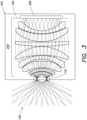
- the front aperture stop 110 allows for use inside a cold cavity, as shown in FIG. 3 , for example.
- the eyepiece 200 can be contained with a cold cavity or housing 310, such as a dewar or other cryo-vac chamber.
- the housing 310 may have an optically transparent window positioned coincident with the aperture stop 120.
- the corrector plate 110 can be integrated with the window of the housing 310, or may be placed inside the housing, very close to the aperture stop 120.
- An infrared detector 320 such as a focal plane array, for example, can be positioned inside the housing 310 (for cryogenic cooling) at the image plane 140.
- Embodiments of the optical system 100 constructed according to the designs shown and described herein, such as, but not limited to the optical prescription given in FIG. 2 may provide a high resolution, low-aberration refractive optical train for two-color infrared imaging.
Landscapes
- Physics & Mathematics (AREA)
- General Physics & Mathematics (AREA)
- Optics & Photonics (AREA)
- Health & Medical Sciences (AREA)
- Toxicology (AREA)
- Lenses (AREA)
Applications Claiming Priority (3)
| Application Number | Priority Date | Filing Date | Title |
|---|---|---|---|
| US15/676,419 US10509210B2 (en) | 2017-08-14 | 2017-08-14 | Two-color very wide field of view refractive eyepiece-type optical form |
| PCT/US2018/033868 WO2019036083A1 (en) | 2017-08-14 | 2018-05-22 | OPTICAL TYPE OF REFLECTIVE OCULAR TYPE WITH VERY LARGE FIELD OF VIEW WITH TWO COLORS |
| EP18731637.7A EP3669226B1 (de) | 2017-08-14 | 2018-05-22 | Zweifarbige refraktive okularartige optische form mit sehr grossem sichtfeld |
Related Parent Applications (2)
| Application Number | Title | Priority Date | Filing Date |
|---|---|---|---|
| EP18731637.7A Division-Into EP3669226B1 (de) | 2017-08-14 | 2018-05-22 | Zweifarbige refraktive okularartige optische form mit sehr grossem sichtfeld |
| EP18731637.7A Division EP3669226B1 (de) | 2017-08-14 | 2018-05-22 | Zweifarbige refraktive okularartige optische form mit sehr grossem sichtfeld |
Publications (3)
| Publication Number | Publication Date |
|---|---|
| EP4235250A2 true EP4235250A2 (de) | 2023-08-30 |
| EP4235250A3 EP4235250A3 (de) | 2023-10-04 |
| EP4235250B1 EP4235250B1 (de) | 2025-09-03 |
Family
ID=62621010
Family Applications (2)
| Application Number | Title | Priority Date | Filing Date |
|---|---|---|---|
| EP23173417.9A Active EP4235250B1 (de) | 2017-08-14 | 2018-05-22 | Zweifarbige refraktive okularartige optische form mit sehr grossem sichtfeld |
| EP18731637.7A Active EP3669226B1 (de) | 2017-08-14 | 2018-05-22 | Zweifarbige refraktive okularartige optische form mit sehr grossem sichtfeld |
Family Applications After (1)
| Application Number | Title | Priority Date | Filing Date |
|---|---|---|---|
| EP18731637.7A Active EP3669226B1 (de) | 2017-08-14 | 2018-05-22 | Zweifarbige refraktive okularartige optische form mit sehr grossem sichtfeld |
Country Status (4)
| Country | Link |
|---|---|
| US (1) | US10509210B2 (de) |
| EP (2) | EP4235250B1 (de) |
| IL (1) | IL270712B (de) |
| WO (1) | WO2019036083A1 (de) |
Families Citing this family (11)
| Publication number | Priority date | Publication date | Assignee | Title |
|---|---|---|---|---|
| TWI684024B (zh) | 2018-07-04 | 2020-02-01 | 大立光電股份有限公司 | 攝影光學鏡組、取像裝置及電子裝置 |
| TWI691751B (zh) | 2019-06-14 | 2020-04-21 | 大立光電股份有限公司 | 光學攝影鏡頭組、取像裝置及電子裝置 |
| TWI788621B (zh) * | 2020-01-17 | 2023-01-01 | 先進光電科技股份有限公司 | 光學成像系統 |
| CA3170860A1 (en) * | 2020-02-21 | 2021-08-26 | Tornado Spectral Systems Inc. | Optical spectroscopy probe configurations for focusing light to a portion of a sample |
| TWI743721B (zh) | 2020-03-04 | 2021-10-21 | 大立光電股份有限公司 | 取像用光學鏡片組、取像裝置及電子裝置 |
| CN111580250A (zh) * | 2020-05-28 | 2020-08-25 | 中国科学院西安光学精密机械研究所 | 一种共孔径可见长波红外双色光学系统 |
| US11268860B2 (en) | 2020-07-24 | 2022-03-08 | Raytheon Company | Radiometric calibration of detector |
| TWI745057B (zh) | 2020-08-28 | 2021-11-01 | 大立光電股份有限公司 | 光學影像鏡片組、取像裝置及電子裝置 |
| US11906881B2 (en) * | 2020-12-03 | 2024-02-20 | Direct Supply, Inc. | Medical mattress failure detection device |
| CN114089511B (zh) * | 2021-11-26 | 2024-01-16 | 湖北久之洋红外系统股份有限公司 | 甚宽波段透射式望远光学系统 |
| CN115356833B (zh) * | 2022-08-16 | 2024-12-31 | 西安工业大学 | 一种基于六边形环带排布的共光路复眼光学系统 |
Family Cites Families (8)
| Publication number | Priority date | Publication date | Assignee | Title |
|---|---|---|---|---|
| US4507551A (en) | 1983-03-14 | 1985-03-26 | Honeywell Inc. | Optical detection system having a detector lens comprising a rear landscape lens |
| US4827130A (en) | 1987-10-22 | 1989-05-02 | General Electric Company | Selectable field infrared imager and lens set |
| US20030102435A1 (en) | 2001-11-20 | 2003-06-05 | Mark Myers | Multiband, single element wide field of view infrared imaging system |
| US7369303B2 (en) | 2006-02-03 | 2008-05-06 | Janos Technology Inc. | Dual band lens system incorporating molded chalcogenide |
| US8044355B2 (en) * | 2007-07-12 | 2011-10-25 | Raytheon Company | System and method for viewing an area using an optical system positioned inside of a dewar |
| US9110276B2 (en) | 2012-01-20 | 2015-08-18 | Raytheon Company | Full-field GEO imager optics with extended spectral coverage |
| US9225914B2 (en) * | 2012-06-29 | 2015-12-29 | Raytheon Company | Infrared imaging system |
| US10670841B2 (en) * | 2017-07-20 | 2020-06-02 | Raytheon Company | Two-color inverse telephoto refractive optical form with external pupil for cold shielding |
-
2017
- 2017-08-14 US US15/676,419 patent/US10509210B2/en active Active
-
2018
- 2018-05-22 EP EP23173417.9A patent/EP4235250B1/de active Active
- 2018-05-22 WO PCT/US2018/033868 patent/WO2019036083A1/en not_active Ceased
- 2018-05-22 EP EP18731637.7A patent/EP3669226B1/de active Active
-
2019
- 2019-11-17 IL IL270712A patent/IL270712B/en active IP Right Grant
Also Published As
| Publication number | Publication date |
|---|---|
| EP3669226A1 (de) | 2020-06-24 |
| EP3669226B1 (de) | 2023-07-19 |
| US20190049705A1 (en) | 2019-02-14 |
| EP4235250A3 (de) | 2023-10-04 |
| WO2019036083A1 (en) | 2019-02-21 |
| EP4235250B1 (de) | 2025-09-03 |
| US10509210B2 (en) | 2019-12-17 |
| IL270712B (en) | 2021-04-29 |
| IL270712A (en) | 2020-01-30 |
Similar Documents
| Publication | Publication Date | Title |
|---|---|---|
| EP4235250B1 (de) | Zweifarbige refraktive okularartige optische form mit sehr grossem sichtfeld | |
| US8101918B1 (en) | Re-imaging infrared lenses | |
| US9297987B2 (en) | Wide field athermalized orthoscopic lens system | |
| US8867140B2 (en) | Low distortion athermalized imaging lens | |
| US7369303B2 (en) | Dual band lens system incorporating molded chalcogenide | |
| US20210003830A1 (en) | Compact dual-band sensor | |
| US20120013706A1 (en) | Infrared wide field imaging system integrated in a vacuum housing | |
| EP3642657B1 (de) | Weitwinkel-mwir f-theta-linse | |
| US7280273B2 (en) | Method and system for simultaneously imaging in the near infrared and short wave infrared spectrums | |
| GB2578679A (en) | Orthoscopic projection lens | |
| JP6567764B2 (ja) | デュアル瞳孔デュアルバンドの広視野再結像光学システム | |
| IL270713A (en) | Bi-color inverted telephoto breaking optical shape with external pupil for cold shielding | |
| RU2385475C1 (ru) | Светосильный широкоугольный объектив для инфракрасной области спектра (варианты) | |
| US20160116719A1 (en) | Compact multispectral wide angle refractive optical system | |
| Greisukh et al. | Passive mechanical athermalization of thermal imaging zoom lenses coupled to an uncooled infrared matrix detector | |
| Fan et al. | Design of high ratio middle infrared continuous zoom optical system | |
| CN114002808A (zh) | 一种红外成像光学系统 | |
| Zhang et al. | Ultrathin cameras using annular folded optics | |
| RU2842491C1 (ru) | Зеркально-линзовый панкратический объектив | |
| Ruirui et al. | Ultrathin cameras using annular folded optics | |
| Mao et al. | Design of refractive fore-optics with wide field of view and waveband for miniature imaging spectrometer | |
| Gong et al. | Design of an off-axis three-mirror system with high speed for hyperspectral imagers | |
| Thibault et al. | Fast camera objective design for spectrograph of Mont Mégantique telescope |
Legal Events
| Date | Code | Title | Description |
|---|---|---|---|
| PUAI | Public reference made under article 153(3) epc to a published international application that has entered the european phase |
Free format text: ORIGINAL CODE: 0009012 |
|
| STAA | Information on the status of an ep patent application or granted ep patent |
Free format text: STATUS: THE APPLICATION HAS BEEN PUBLISHED |
|
| AC | Divisional application: reference to earlier application |
Ref document number: 3669226 Country of ref document: EP Kind code of ref document: P |
|
| AK | Designated contracting states |
Kind code of ref document: A2 Designated state(s): AL AT BE BG CH CY CZ DE DK EE ES FI FR GB GR HR HU IE IS IT LI LT LU LV MC MK MT NL NO PL PT RO RS SE SI SK SM TR |
|
| PUAL | Search report despatched |
Free format text: ORIGINAL CODE: 0009013 |
|
| AK | Designated contracting states |
Kind code of ref document: A3 Designated state(s): AL AT BE BG CH CY CZ DE DK EE ES FI FR GB GR HR HU IE IS IT LI LT LU LV MC MK MT NL NO PL PT RO RS SE SI SK SM TR |
|
| RIC1 | Information provided on ipc code assigned before grant |
Ipc: G02B 13/14 20060101AFI20230829BHEP |
|
| STAA | Information on the status of an ep patent application or granted ep patent |
Free format text: STATUS: REQUEST FOR EXAMINATION WAS MADE |
|
| 17P | Request for examination filed |
Effective date: 20231204 |
|
| RBV | Designated contracting states (corrected) |
Designated state(s): AL AT BE BG CH CY CZ DE DK EE ES FI FR GB GR HR HU IE IS IT LI LT LU LV MC MK MT NL NO PL PT RO RS SE SI SK SM TR |
|
| GRAP | Despatch of communication of intention to grant a patent |
Free format text: ORIGINAL CODE: EPIDOSNIGR1 |
|
| STAA | Information on the status of an ep patent application or granted ep patent |
Free format text: STATUS: GRANT OF PATENT IS INTENDED |
|
| GRAJ | Information related to disapproval of communication of intention to grant by the applicant or resumption of examination proceedings by the epo deleted |
Free format text: ORIGINAL CODE: EPIDOSDIGR1 |
|
| STAA | Information on the status of an ep patent application or granted ep patent |
Free format text: STATUS: REQUEST FOR EXAMINATION WAS MADE |
|
| GRAP | Despatch of communication of intention to grant a patent |
Free format text: ORIGINAL CODE: EPIDOSNIGR1 |
|
| STAA | Information on the status of an ep patent application or granted ep patent |
Free format text: STATUS: GRANT OF PATENT IS INTENDED |
|
| INTG | Intention to grant announced |
Effective date: 20250404 |
|
| INTC | Intention to grant announced (deleted) | ||
| INTG | Intention to grant announced |
Effective date: 20250428 |
|
| GRAS | Grant fee paid |
Free format text: ORIGINAL CODE: EPIDOSNIGR3 |
|
| GRAA | (expected) grant |
Free format text: ORIGINAL CODE: 0009210 |
|
| STAA | Information on the status of an ep patent application or granted ep patent |
Free format text: STATUS: THE PATENT HAS BEEN GRANTED |
|
| AC | Divisional application: reference to earlier application |
Ref document number: 3669226 Country of ref document: EP Kind code of ref document: P |
|
| AK | Designated contracting states |
Kind code of ref document: B1 Designated state(s): AL AT BE BG CH CY CZ DE DK EE ES FI FR GB GR HR HU IE IS IT LI LT LU LV MC MK MT NL NO PL PT RO RS SE SI SK SM TR |
|
| REG | Reference to a national code |
Ref country code: CH Ref legal event code: EP |
|
| REG | Reference to a national code |
Ref country code: DE Ref legal event code: R096 Ref document number: 602018085389 Country of ref document: DE |
|
| REG | Reference to a national code |
Ref country code: IE Ref legal event code: FG4D |
|
| REG | Reference to a national code |
Ref country code: NL Ref legal event code: MP Effective date: 20250903 |
|
| PG25 | Lapsed in a contracting state [announced via postgrant information from national office to epo] |
Ref country code: NO Free format text: LAPSE BECAUSE OF FAILURE TO SUBMIT A TRANSLATION OF THE DESCRIPTION OR TO PAY THE FEE WITHIN THE PRESCRIBED TIME-LIMIT Effective date: 20251203 |
|
| REG | Reference to a national code |
Ref country code: LT Ref legal event code: MG9D |
|
| PG25 | Lapsed in a contracting state [announced via postgrant information from national office to epo] |
Ref country code: FI Free format text: LAPSE BECAUSE OF FAILURE TO SUBMIT A TRANSLATION OF THE DESCRIPTION OR TO PAY THE FEE WITHIN THE PRESCRIBED TIME-LIMIT Effective date: 20250903 |
|
| PG25 | Lapsed in a contracting state [announced via postgrant information from national office to epo] |
Ref country code: HR Free format text: LAPSE BECAUSE OF FAILURE TO SUBMIT A TRANSLATION OF THE DESCRIPTION OR TO PAY THE FEE WITHIN THE PRESCRIBED TIME-LIMIT Effective date: 20250903 |
|
| PG25 | Lapsed in a contracting state [announced via postgrant information from national office to epo] |
Ref country code: GR Free format text: LAPSE BECAUSE OF FAILURE TO SUBMIT A TRANSLATION OF THE DESCRIPTION OR TO PAY THE FEE WITHIN THE PRESCRIBED TIME-LIMIT Effective date: 20251204 |
|
| PG25 | Lapsed in a contracting state [announced via postgrant information from national office to epo] |
Ref country code: SE Free format text: LAPSE BECAUSE OF FAILURE TO SUBMIT A TRANSLATION OF THE DESCRIPTION OR TO PAY THE FEE WITHIN THE PRESCRIBED TIME-LIMIT Effective date: 20250903 |
|
| PG25 | Lapsed in a contracting state [announced via postgrant information from national office to epo] |
Ref country code: LV Free format text: LAPSE BECAUSE OF FAILURE TO SUBMIT A TRANSLATION OF THE DESCRIPTION OR TO PAY THE FEE WITHIN THE PRESCRIBED TIME-LIMIT Effective date: 20250903 |
|
| PG25 | Lapsed in a contracting state [announced via postgrant information from national office to epo] |
Ref country code: PL Free format text: LAPSE BECAUSE OF FAILURE TO SUBMIT A TRANSLATION OF THE DESCRIPTION OR TO PAY THE FEE WITHIN THE PRESCRIBED TIME-LIMIT Effective date: 20250903 Ref country code: BG Free format text: LAPSE BECAUSE OF FAILURE TO SUBMIT A TRANSLATION OF THE DESCRIPTION OR TO PAY THE FEE WITHIN THE PRESCRIBED TIME-LIMIT Effective date: 20250903 |
|
| PG25 | Lapsed in a contracting state [announced via postgrant information from national office to epo] |
Ref country code: RS Free format text: LAPSE BECAUSE OF FAILURE TO SUBMIT A TRANSLATION OF THE DESCRIPTION OR TO PAY THE FEE WITHIN THE PRESCRIBED TIME-LIMIT Effective date: 20251203 |
|
| PG25 | Lapsed in a contracting state [announced via postgrant information from national office to epo] |
Ref country code: ES Free format text: LAPSE BECAUSE OF FAILURE TO SUBMIT A TRANSLATION OF THE DESCRIPTION OR TO PAY THE FEE WITHIN THE PRESCRIBED TIME-LIMIT Effective date: 20250903 |
|
| REG | Reference to a national code |
Ref country code: AT Ref legal event code: MK05 Ref document number: 1833722 Country of ref document: AT Kind code of ref document: T Effective date: 20250903 |
|
| PG25 | Lapsed in a contracting state [announced via postgrant information from national office to epo] |
Ref country code: NL Free format text: LAPSE BECAUSE OF FAILURE TO SUBMIT A TRANSLATION OF THE DESCRIPTION OR TO PAY THE FEE WITHIN THE PRESCRIBED TIME-LIMIT Effective date: 20250903 |
|
| PG25 | Lapsed in a contracting state [announced via postgrant information from national office to epo] |
Ref country code: SM Free format text: LAPSE BECAUSE OF FAILURE TO SUBMIT A TRANSLATION OF THE DESCRIPTION OR TO PAY THE FEE WITHIN THE PRESCRIBED TIME-LIMIT Effective date: 20250903 |
|
| PG25 | Lapsed in a contracting state [announced via postgrant information from national office to epo] |
Ref country code: AT Free format text: LAPSE BECAUSE OF FAILURE TO SUBMIT A TRANSLATION OF THE DESCRIPTION OR TO PAY THE FEE WITHIN THE PRESCRIBED TIME-LIMIT Effective date: 20250903 |
|
| PG25 | Lapsed in a contracting state [announced via postgrant information from national office to epo] |
Ref country code: IT Free format text: LAPSE BECAUSE OF FAILURE TO SUBMIT A TRANSLATION OF THE DESCRIPTION OR TO PAY THE FEE WITHIN THE PRESCRIBED TIME-LIMIT Effective date: 20250903 |
|
| PG25 | Lapsed in a contracting state [announced via postgrant information from national office to epo] |
Ref country code: IS Free format text: LAPSE BECAUSE OF FAILURE TO SUBMIT A TRANSLATION OF THE DESCRIPTION OR TO PAY THE FEE WITHIN THE PRESCRIBED TIME-LIMIT Effective date: 20260103 |
|
| PG25 | Lapsed in a contracting state [announced via postgrant information from national office to epo] |
Ref country code: PT Free format text: LAPSE BECAUSE OF FAILURE TO SUBMIT A TRANSLATION OF THE DESCRIPTION OR TO PAY THE FEE WITHIN THE PRESCRIBED TIME-LIMIT Effective date: 20260105 Ref country code: CZ Free format text: LAPSE BECAUSE OF FAILURE TO SUBMIT A TRANSLATION OF THE DESCRIPTION OR TO PAY THE FEE WITHIN THE PRESCRIBED TIME-LIMIT Effective date: 20250903 |
|
| PG25 | Lapsed in a contracting state [announced via postgrant information from national office to epo] |
Ref country code: EE Free format text: LAPSE BECAUSE OF FAILURE TO SUBMIT A TRANSLATION OF THE DESCRIPTION OR TO PAY THE FEE WITHIN THE PRESCRIBED TIME-LIMIT Effective date: 20250903 Ref country code: SK Free format text: LAPSE BECAUSE OF FAILURE TO SUBMIT A TRANSLATION OF THE DESCRIPTION OR TO PAY THE FEE WITHIN THE PRESCRIBED TIME-LIMIT Effective date: 20250903 |