EP4235182B1 - Microcolumn gel card, and sample adding mechanism and method - Google Patents
Microcolumn gel card, and sample adding mechanism and method Download PDFInfo
- Publication number
- EP4235182B1 EP4235182B1 EP22871110.7A EP22871110A EP4235182B1 EP 4235182 B1 EP4235182 B1 EP 4235182B1 EP 22871110 A EP22871110 A EP 22871110A EP 4235182 B1 EP4235182 B1 EP 4235182B1
- Authority
- EP
- European Patent Office
- Prior art keywords
- sample adding
- tubular
- column
- fixing plate
- columns
- Prior art date
- Legal status (The legal status is an assumption and is not a legal conclusion. Google has not performed a legal analysis and makes no representation as to the accuracy of the status listed.)
- Active
Links
Images


Classifications
-
- B—PERFORMING OPERATIONS; TRANSPORTING
- B01—PHYSICAL OR CHEMICAL PROCESSES OR APPARATUS IN GENERAL
- B01L—CHEMICAL OR PHYSICAL LABORATORY APPARATUS FOR GENERAL USE
- B01L3/00—Containers or dishes for laboratory use, e.g. laboratory glassware; Droppers
- B01L3/50—Containers for the purpose of retaining a material to be analysed, e.g. test tubes
- B01L3/502—Containers for the purpose of retaining a material to be analysed, e.g. test tubes with fluid transport, e.g. in multi-compartment structures
- B01L3/5021—Test tubes specially adapted for centrifugation purposes
-
- B—PERFORMING OPERATIONS; TRANSPORTING
- B01—PHYSICAL OR CHEMICAL PROCESSES OR APPARATUS IN GENERAL
- B01L—CHEMICAL OR PHYSICAL LABORATORY APPARATUS FOR GENERAL USE
- B01L3/00—Containers or dishes for laboratory use, e.g. laboratory glassware; Droppers
- B01L3/50—Containers for the purpose of retaining a material to be analysed, e.g. test tubes
- B01L3/502—Containers for the purpose of retaining a material to be analysed, e.g. test tubes with fluid transport, e.g. in multi-compartment structures
- B01L3/5023—Containers for the purpose of retaining a material to be analysed, e.g. test tubes with fluid transport, e.g. in multi-compartment structures with a sample being transported to, and subsequently stored in an absorbent for analysis
-
- B—PERFORMING OPERATIONS; TRANSPORTING
- B01—PHYSICAL OR CHEMICAL PROCESSES OR APPARATUS IN GENERAL
- B01L—CHEMICAL OR PHYSICAL LABORATORY APPARATUS FOR GENERAL USE
- B01L3/00—Containers or dishes for laboratory use, e.g. laboratory glassware; Droppers
- B01L3/50—Containers for the purpose of retaining a material to be analysed, e.g. test tubes
- B01L3/502—Containers for the purpose of retaining a material to be analysed, e.g. test tubes with fluid transport, e.g. in multi-compartment structures
- B01L3/5025—Containers for the purpose of retaining a material to be analysed, e.g. test tubes with fluid transport, e.g. in multi-compartment structures for parallel transport of multiple samples
-
- B—PERFORMING OPERATIONS; TRANSPORTING
- B01—PHYSICAL OR CHEMICAL PROCESSES OR APPARATUS IN GENERAL
- B01L—CHEMICAL OR PHYSICAL LABORATORY APPARATUS FOR GENERAL USE
- B01L3/00—Containers or dishes for laboratory use, e.g. laboratory glassware; Droppers
- B01L3/50—Containers for the purpose of retaining a material to be analysed, e.g. test tubes
- B01L3/508—Rigid containers without fluid transport within
- B01L3/5085—Rigid containers without fluid transport within for multiple samples, e.g. microtitration plates
-
- B—PERFORMING OPERATIONS; TRANSPORTING
- B01—PHYSICAL OR CHEMICAL PROCESSES OR APPARATUS IN GENERAL
- B01L—CHEMICAL OR PHYSICAL LABORATORY APPARATUS FOR GENERAL USE
- B01L3/00—Containers or dishes for laboratory use, e.g. laboratory glassware; Droppers
- B01L3/50—Containers for the purpose of retaining a material to be analysed, e.g. test tubes
- B01L3/508—Rigid containers without fluid transport within
- B01L3/5085—Rigid containers without fluid transport within for multiple samples, e.g. microtitration plates
- B01L3/50853—Rigid containers without fluid transport within for multiple samples, e.g. microtitration plates with covers or lids
-
- B—PERFORMING OPERATIONS; TRANSPORTING
- B01—PHYSICAL OR CHEMICAL PROCESSES OR APPARATUS IN GENERAL
- B01L—CHEMICAL OR PHYSICAL LABORATORY APPARATUS FOR GENERAL USE
- B01L2200/00—Solutions for specific problems relating to chemical or physical laboratory apparatus
- B01L2200/06—Fluid handling related problems
- B01L2200/0631—Purification arrangements, e.g. solid phase extraction [SPE]
-
- B—PERFORMING OPERATIONS; TRANSPORTING
- B01—PHYSICAL OR CHEMICAL PROCESSES OR APPARATUS IN GENERAL
- B01L—CHEMICAL OR PHYSICAL LABORATORY APPARATUS FOR GENERAL USE
- B01L2200/00—Solutions for specific problems relating to chemical or physical laboratory apparatus
- B01L2200/16—Reagents, handling or storing thereof
-
- B—PERFORMING OPERATIONS; TRANSPORTING
- B01—PHYSICAL OR CHEMICAL PROCESSES OR APPARATUS IN GENERAL
- B01L—CHEMICAL OR PHYSICAL LABORATORY APPARATUS FOR GENERAL USE
- B01L2300/00—Additional constructional details
- B01L2300/06—Auxiliary integrated devices, integrated components
- B01L2300/069—Absorbents; Gels to retain a fluid
-
- B—PERFORMING OPERATIONS; TRANSPORTING
- B01—PHYSICAL OR CHEMICAL PROCESSES OR APPARATUS IN GENERAL
- B01L—CHEMICAL OR PHYSICAL LABORATORY APPARATUS FOR GENERAL USE
- B01L2400/00—Moving or stopping fluids
- B01L2400/04—Moving fluids with specific forces or mechanical means
- B01L2400/0403—Moving fluids with specific forces or mechanical means specific forces
- B01L2400/0409—Moving fluids with specific forces or mechanical means specific forces centrifugal forces
-
- B—PERFORMING OPERATIONS; TRANSPORTING
- B01—PHYSICAL OR CHEMICAL PROCESSES OR APPARATUS IN GENERAL
- B01L—CHEMICAL OR PHYSICAL LABORATORY APPARATUS FOR GENERAL USE
- B01L3/00—Containers or dishes for laboratory use, e.g. laboratory glassware; Droppers
- B01L3/50—Containers for the purpose of retaining a material to be analysed, e.g. test tubes
- B01L3/508—Rigid containers without fluid transport within
- B01L3/5085—Rigid containers without fluid transport within for multiple samples, e.g. microtitration plates
- B01L3/50857—Rigid containers without fluid transport within for multiple samples, e.g. microtitration plates using arrays or bundles of open capillaries for holding samples
Definitions
- the present invention relates to the field of medical devices, in particular to a micro-column gel card, a sample adding mechanism and a method.
- Blood type detection technology has a history of more than 100 years, gradually developing from original classical methods, such as a slide method, a paper method, and a tube method, to a micro-titration plate method, a solid phase method, a magnetized red blood cell method, and a gel typing detection method published in 1990.
- the micro-column gel method is a recommended method for a safe blood transfusion examination worldwide.
- a micro-column gel card is mainly used in a blood type test before surgery and blood transfusion and screening of hemolytic disease of the newborn before or in pregnancy.
- a current novel card-type detection method has replaced a traditional blood detection method, becomes a new detection method that is more convenient, more stable, and more accurate, and has been widely promoted.
- the micro-column gel card is generally formed by connecting a plurality of miniature tubular columns with special shapes in parallel.
- a sample adding column and a funnel-shaped "reaction tank” are provided above a tubular column.
- a miniature tubular column is provided at a lower end of the reaction tank.
- the miniature tubular column contains specific antibodies filled according to detection requirements of different items and non-soluble gel particles with certain physical properties and stable chemical properties. Added samples and reagents are reacted in the reaction tank first, and then are centrifuged and interpreted by an instrument.
- the current micro-column gel cards are generally 6-column or 8-column. Due to limitations on the number of pore columns, the detection speed is relatively low when the micro-column gel cards are used with automated instruments. Therefore, it is urgent to improve the micro-column gel cards, so as not to affect the accuracy of detection results while improving the detection efficiency of large-scale experiments.
- US 8,496,878 B2 discloses an immunodiagnostic test card including a flat planar member and at least one dilution chamber that is supported by the flat planar member, wherein the at least one dilution chamber can be disposed adjacent chambers used for testing a patient sample that are provided on the immunodiagnostic test card or can be provided separately.
- the present invention provides a micro-column gel card, a sample adding mechanism, and a method.
- a micro-column gel card including a fixing plate and a plurality of tubular columns arranged and fixed through the fixing plate, characterized in that, the tubular columns are fixed to two sides of the fixing plate respectively, and the tubular columns located on the two sides of the fixing plate are arranged in a staggered manner, any tubular column includes a sample adding cavity, a reaction cavity, and a gel column, the gel column is configured to load a gel reagent, the sample adding cavity is provided above the gel column, the reaction cavity is connected between the sample adding cavity and the gel column, and a central axis of the sample adding cavity and a central axis of the gel column do not coincide.
- tubular columns on the two sides of the fixing plate are in a centrosymmetric form. In this way, it is ensured that the micro-column gel card may be placed in automated equipment along all directions, thereby reducing the error rate during an actual operation.
- the center-to-center spacing between any two adjacent tubular columns among the tubular columns is equal, preferably, to 9 mm.
- the center-to-center spacing between any two adjacent tubular columns is equal. That is, the center-to-center spacing between adjacent tubular columns on the same side of the fixing plate and the center-to-center spacing between adjacent tubular columns on different sides of the fixing plate are all equal, whereby the centers of three adjacent tubular columns on the two sides of the fixing plate are connected to form an equilateral triangle, in order to maintain a specific relationship between displacement distances of the sample adding device in different tubular columns and the center-to-center spacing between adjacent tubular columns when the micro-column gel card is placed in an automated instrument to perform an experiment, thereby simplifying logic control.
- any two gel columns are parallel to each other and front projections do not overlap. In this way, any two gel columns are completely non-overlapping, so as to ensure that the interference of interpretation between the tubular columns in the instrumental interpretation of each gel column when the micro-column gel card is used in a micro-column gel experiment is reduced.
- the sealing layer is also included, a film-covered column is provided at an opening of the sample adding cavity, the film-covered column is of an annular bulged structure, an inner ring step is provided on an inner side wall of the film-covered column and the sealing layer is in sealing connection with the film-covered column.
- a sealing material such as environment friendly glue
- a sealing material used in sealing usually has a certain fluidity.
- first reinforcing rib is provided outside the sample adding cavity of each of the tubular columns, and a second reinforcing rib is provided outside the gel column of each tubular column.
- first reinforcing rib and the second reinforcing rib are provided in order to make the micro-column gel card more stable structurally and less deformable.
- the sample adding cavity has an outer diameter of 8-10 mm
- the gel column has an outer diameter of 2-4 mm and an inner diameter of 1-1.5 mm
- the reaction cavity has a depth of 3-6 mm
- the gel column has a depth of 15-20 mm.
- the reaction effect of samples/reagents in the reaction cavity is effectively improved by controlling the ratio of pore sizes of the sample adding cavity and the gel column and the depth of the reaction cavity.
- the ratio of the pore sizes of the sample adding cavity and the gel column is larger or the depth of the reaction cavity is smaller, the inclination of a conical surface of the reaction cavity is smaller, the samples/reagents are not easily spread and dispersed, and the reaction effect is affected.
- the two sides of the fixing plate are provided with an equal number of tubular columns, the tubular columns on one side of the fixing plate are set to a first tubular column group, the tubular columns on the other side are set to a second tubular column group, and a staggered spacing between the first tubular column group and the second tubular column group is one-half of the center-to-center spacing between adjacent tubular columns.
- the tubular columns on the two sides are arranged in a staggered manner at a distance of half the outer diameter of the sample adding cavity.
- the lateral dimension of the whole micro-column gel card can be reduced to a large extent, and the space utilization can be improved.
- the fixing plate includes a lower clamp body and an upper clamp body, and a minimum distance between edges of the sample adding cavities of the tubular columns on both sides of the first tubular column group and the second tubular column group and an edge of the upper clamp body is 1-3 mm.
- a gripper of automated equipment to grasp the micro-column gel card while improving the space utilization. If the distance between the edges of the sample adding cavities of the tubular columns on the two sides and the edge of the fixing plate is too large, the size of the whole micro-column gel card is large, and the space utilization is low. If the distance between the edges of the sample adding cavities of the tubular columns on the two sides and the edge of the fixing plate is too small, the gripper of the automated equipment may have the problems of unstable grasping and falling when grasping the micro-column gel card.
- first tubular column group and the second tubular column group each include N tubular columns, where N is a natural number of not less than 4, and N is an even number.
- a sample adding mechanism configured for sample adding on the foregoing micro-column gel card, the sample adding mechanism includes N /2 sample adding devices, a distance between any two adjacent sample adding devices is twice a center-to-center spacing between adjacent tubular columns, and the sample adding mechanism has a freedom of motion in X, Y, and Z directions.
- a method for performing, by the sample adding mechanism, sample adding on the foregoing micro-column gel card includes:
- the sample adding mechanism performs sample adding in a staggered manner on the foregoing micro-column gel card according to the sample adding method, which can greatly avoid interference of simultaneous sample adding between adjacent tubular columns or possible cross-contamination problems, and the like.
- a sample adding mechanism configured for sample adding on the foregoing micro-column gel card.
- the sample adding mechanism includes a plurality of sample adding devices in a distribution and arrangement form adapted to a distribution and arrangement form of tubular columns on the micro-column gel card, and the sample adding mechanism has a freedom of motion in X, Y, and Z directions. In this way, the sample adding mechanism may complete the sample adding process for each tubular column on the foregoing micro-column gel card at once, thereby greatly improving working efficiency.
- the present invention provides a micro-column gel card, and a sample adding mechanism and method in combination with the structural features of the present invention.
- the micro-column gel card includes a fixing plate and a plurality of tubular columns arranged and fixed through the fixing plate.
- the tubular columns are fixed to two sides of the fixing plate respectively, and the tubular columns located on the two sides of the fixing plate are arranged in a staggered manner.
- Any tubular column includes a sample adding cavity, a reaction cavity, and a gel column.
- the gel column is configured to load a gel reagent.
- the sample adding cavity is provided above the gel column.
- the reaction cavity is connected between the sample adding cavity and the gel column.
- a central axis of the sample adding cavity and a central axis of the gel column do not coincide.
- the tubular columns are designed in a double-row staggered manner. Compared with a single-row micro-column gel card of the same type, the design of the double-row tubular columns increases the number of the tubular columns to multiply the detection efficiency. Meanwhile, the staggered design of the double-row tubular columns can ensure that adjacent tubular columns do not overlap, thereby reducing mutual interference between the tubular columns in an experimental interpretation process.
- an eccentric design between the sample adding cavity and the gel column facilitates debugging of a sample adding position. When debugging the sample adding position of the sample adding mechanism, an operator only needs to debug the sample adding position based on a central position of the sample adding cavity, which can ensure the consistency of sample adding positions adjusted by different operators to a certain extent.
- a micro-column gel card includes a fixing plate and a plurality of tubular columns 3 arranged and fixed through the fixing plate.
- the tubular columns are fixed to two sides of the fixing plate respectively, and the tubular columns located on the two sides of the fixing plate are arranged in a staggered manner.
- Any tubular column 3 includes a sample adding cavity 301, a reaction cavity 302, and a gel column 303.
- the gel column 303 is configured to load a gel reagent.
- the sample adding cavity 301 is provided above the gel column 303.
- the reaction cavity 302 is connected between the sample adding cavity 301 and the gel column 303.
- a central axis of the sample adding cavity 301 and a central axis of the gel column 303 do not coincide.
- any two adjacent tubular columns do not overlap, so as to ensure that the interference of interpretation between the tubular columns in the instrumental interpretation of each gel column when the micro-column gel card is used in a micro-column gel experiment is reduced.
- it is necessary to first add a sample/reagent for a sufficient reaction In order to prevent the sample/reagent from being directly injected into the gel column, it is usually necessary to inject the sample/reagent into the reaction cavity for a sufficient reaction, and then the sample/reagent is allowed to settle into the gel column through a tube wall under the action of centrifugal force. Then, the result is interpreted.
- the sample adding cavity and the gel column are generally of a concentric design, and an operator needs to perform an appropriate offset step number based on the center of the sample adding cavity when debugging the sample adding position, whereby the sample/reagent can be filled into the reaction cavity.
- the specific offset can only be adjusted according to the experience of the operator. Different operators cannot keep consistent with a preset offset, resulting in uneven and poor consistency of the sample adding positions debugged by different operators.
- the central axis of the sample adding cavity and the central axis of the gel column do not coincide. That is, there is an eccentric design between the sample adding cavity of each tubular column and the gel column.
- the operator When debugging the sample adding position, the operator only needs to debug the sample adding position based on a central position of the sample adding cavity (that is, the central axis of the sample adding cavity), which can ensure the consistency of sample adding positions adjusted by different operators to a certain extent.
- the two sides of the fixing plate are provided with an equal number (eight) of tubular columns, so as to form a double-row sixteen-pore micro-column gel card.
- the tubular columns on the two sides of the fixing plate are in a centrosymmetric form. Vertical projections of the gel column and the sample adding cavity are internally tangent. Any two gel columns are parallel to each other and front projections do not overlap.
- the tubular columns on one side of the fixing plate are set to a first tubular column group (a column group located at the upper row shown in Fig. 4 is the first tubular column group), and the tubular columns on the other side are set to a second tubular column group (a column group located at the lower row shown in Fig.
- the first tubular column group is the first tubular column group). As shown in Fig. 4 , the eight tubular columns in the first tubular column group are set to H1-H8 respectively, and the eight tubular columns in the second tubular column group are set to M1-M8 respectively.
- the center-to-center spacing between any two adjacent tubular columns is equal.
- a staggered spacing between the first tubular column group and the second tubular column group is one-half of the center-to-center spacing between adjacent tubular columns.
- the two groups of tubular columns are in a centrosymmetric form, thereby ensuring that the micro-column gel card may be placed in automated equipment along all directions, and reducing the error rate during an actual operation.
- the center-to-center spacing between adjacent tubular columns is set to d .
- the staggered spacing between H1 and M1, H2 and M2, H3 and M3, H4 and M4, H5 and M5, H6 and M6, H7 and M7, and H8 and M8 are all one-half of the center-to-center spacing between adjacent tubular columns, that is, d/2.
- the sample adding mechanism 5 has a freedom of motion in X, Y, and Z directions.
- the sample adding mechanism 5 includes four sample adding devices ( FIG. 6 shows a corresponding schematic diagram, and it should be noted that Fig. 6 is a schematic diagram drawn for explaining the technical effect of this embodiment, and does not represent an actual structural relationship), which are a first sample adding device 501, a second sample adding device 502, a third sample adding device 503 and a fourth sample adding device 504, respectively.
- a distance between any two adjacent sample adding devices is a center-to-center spacing between adjacent tubular columns, that is, 2d.
- the sample adding mechanism adopts a sample adding method for the double-row sixteen-pore micro-column gel card in this embodiment as shown in Fig. 7 :
- a left side of the fixing plate is set to the first direction and a right side of the fixing plate is set to the second direction.
- S3 The sample adding mechanism is moved until any of sample adding devices on two sides is located above a central axis position of a sample adding cavity of a tubular column near the first direction or the second direction of the edge of the fixing plate in the first tubular column group or the second tubular column group.
- the sample adding mechanism is moved until the first sample adding device 501 is located above a central axis position of a sample adding cavity of a tubular column H1 in the first tubular column group.
- the sample adding mechanism completes sample adding on four tubular columns, such as H1, H3, H5, and H7, in the first tubular column group through the first to fourth sample adding devices.
- the sample adding mechanism is horizontally moved to a first set direction by a distance of d, so as to complete sample adding on the remaining four tubular columns (that is, tubular columns H2, H4, H6, and H8) in the first tubular column group.
- the first set direction is selected as: when the sample-added tubular column near the edge of the fixing plate in the first tubular column group or the second tubular column group is located in the first direction of the fixing plate, the set direction is the second direction, or when the sample-added tubular column near the edge of the fixing plate in the first tubular column group or the second tubular column group is located in the second direction of the fixing plate, the set direction is the first direction.
- the first direction is the left side of the fixing plate
- the second direction is the right side of the fixing plate
- the sample-added tubular column near the edge of the fixing plate in the first tubular column group is a tubular column H1.
- the tubular column H1 is located on the left side of the fixing plate, which is the first direction. Therefore, the first set direction is an opposite direction thereto, and the first set direction is the second direction, which is the right side of the fixing plate.
- the sample adding mechanism is horizontally moved to the right side of the fixing plate or the second direction by a distance of d, so as to complete sample adding on the remaining four tubular columns (that is, tubular columns H2, H4, H6, and H8) in the first tubular column group.
- the sample adding mechanism is selectively horizontally moved to a second set direction by a distance that is one-half or three-seconds of d. Then, the sample adding mechanism is moved towards the second tubular column group by a set distance along a Y direction, whereby the sample adding device near the edge of the fixing plate in the sample adding mechanism is located above the central axis position of the sample adding cavity of the corresponding tubular column, and the sample adding mechanism completes sample adding on N/2 tubular columns in the second tubular column group or the first tubular column group.
- the first to fourth sample adding devices are respectively located above the four tubular columns H2, H4, H6, and H8 in the first tubular column group.
- sample adding is required on the second tubular column group.
- the sample adding mechanism is horizontally moved to a second set direction by a distance that is three-seconds of d.
- the second set direction is the left side of the fixing plate.
- the sample adding mechanism is moved towards the second tubular column group by a set distance along a Y direction.
- the set distance in this embodiment is the distance in the Y direction between the centers of the tubular columns H1 and M1, whereby the sample adding device near the edge of the fixing plate in the sample adding mechanism is located above the central axis position of the sample adding cavity of the corresponding tubular column. That is, the first sample adding device 501 is located above the central axis position of the sample adding cavity of the tubular column M1 in the second tubular column group. Then, the sample adding mechanism completes sample adding on four tubular columns M1, M3, M5, and M7 in the second tubular column group.
- the sample adding mechanism is horizontally moved to a third set direction of the edge of the fixing plate by a distance of d, so as to complete sample adding on four tubular columns M2, M4, M6, and M8 in the second tubular column group.
- the third set direction is selected as: when the sample-added tubular column near the edge of the fixing plate in the second tubular column group is located in the first direction of the fixing plate, the set direction is the second direction, or when the sample-added tubular column near the edge of the fixing plate in the second tubular column group or the first tubular column group is located in the second direction of the fixing plate, the set direction is the first direction.
- the sample-added tubular column near the edge of the fixing plate in the second tubular column group is a tubular column M1.
- the tubular column M1 is located on the left side of the fixing plate, which is the first direction. Therefore, the third set direction is an opposite direction thereto, and the third set direction is the second direction, which is the right side of the fixing plate. Then the sample adding mechanism is horizontally moved to the right side of the fixing plate or the second direction by a distance of d, so as to complete sample adding on the remaining four tubular columns (that is, tubular columns M2, M4, M6, and M8) in the second tubular column group.
- the sample adding mechanism performs sample adding in a staggered manner on the foregoing micro-column gel card according to the sample adding method, which can greatly avoid interference of simultaneous sample adding between adjacent tubular columns or possible cross-contamination problems, and the like.
- the center-to-center spacing between any two adjacent tubular columns is equal. That is, the center-to-center spacing between adjacent tubular columns on the same side of the fixing plate and the center-to-center spacing between adjacent tubular columns on different sides of the fixing plate are all equal, whereby the centers of three adjacent tubular columns on the two sides of the fixing plate are connected to form an equilateral triangle ( Fig. 5 shows a corresponding schematic diagram, and it should be noted that Fig. 5 is a schematic diagram drawn for explaining the technical effect of this embodiment, and does not represent an actual structural relationship). As shown in Fig.
- the center-to-center spacing of H1, M1, and M2 is equal, and the center-to-center spacing of H1, H2, and M2 is also equal, and so on.
- One-by-one descriptions will be omitted herein.
- a specific relationship is maintained between displacement distances of the sample adding device in different tubular columns and the center-to-center spacing between adjacent tubular columns when the micro-column gel card is placed in an automated instrument to perform an experiment, thereby simplifying logic control. That is, when the placement position of the micro-column gel card is offset or when the sample adding device is out of step, the offset of all pore positions is consistent, and the relative offset and offset range of the sample adding position are also consistent.
- the position range of sample injection points on the reaction cavity of each tubular column relative to the reaction cavity is kept consistent under the displacement distance originally set.
- the placement position of the micro-column gel card is offset, if the sample injection points of the sample adding device on a reaction cavity of a certain tubular column are still located within the range of the reaction cavity, it may be concluded that the sample injection points of all the tubular columns are located within the range of the reaction cavity, and it may be properly considered that the sample adding position is not readjusted.
- the sample adding position needs to be adjusted, it is only necessary to use a tubular column as a sample adding position adjustment object. Specifically, as shown in the schematic diagram of Fig.
- the sample injection points of three tubular columns shown in the diagram should be points A1, B1, and C1.
- the position ranges of points A2, B2, and C2 relative to the reaction cavities of the respective tubular columns are consistent.
- the offset position ranges of points A2, B2, and C2 relative to the reaction cavities of the respective tubular columns are approximately 15° in a horizontal direction and the distances to the outer walls of the reaction cavities are also consistent, which all fall within the position ranges of the reaction cavities of the respective columns without exceeding.
- the sample adding mechanism 5 has a freedom of motion in X, Y, and Z directions.
- the sample adding mechanism 5 includes four sample adding devices ( FIG. 6 shows a corresponding schematic diagram, and it should be noted that Fig. 6 is a schematic diagram drawn for explaining the technical effect of this embodiment, and does not represent an actual structural relationship), which are a first sample adding device 501, a second sample adding device 502, a third sample adding device 503 and a fourth sample adding device 504, respectively.
- a distance between any two adjacent sample adding devices is a center-to-center spacing between adjacent tubular columns, that is, 2d.
- the sample adding mechanism adopts a sample adding method for the double-row sixteen-pore micro-column gel card in this embodiment as shown in Fig. 8 .
- One side of the edge of the fixing plate is set to a first direction and the other side is set to a second direction.
- a left side of the fixing plate is set to the first direction and a right side of the fixing plate is set to the second direction.
- S10 The sample adding mechanism is moved until any of sample adding devices on two sides is located above a central axis position of a sample adding cavity of a tubular column near the first direction or the second direction of the edge of the fixing plate in the first tubular column group or the second tubular column group.
- the sample adding mechanism is moved until the fourth sample adding device 504 is located above a central axis position of a sample adding cavity of a tubular column H8 in the first tubular column group.
- the sample adding mechanism completes sample adding on four tubular columns H2, H4, H6, and H8 in the first tubular column group through the first to fourth sample adding devices.
- the sample adding mechanism is horizontally moved to a first set direction by a distance of d, so as to complete sample adding on the remaining four tubular columns (that is, tubular columns H1, H3, H5, and H7) in the first tubular column group.
- the first set direction is selected as: when the sample-added tubular column near the edge of the fixing plate in the first tubular column group or the second tubular column group is located in the first direction of the fixing plate, the set direction is the second direction, or when the sample-added tubular column near the edge of the fixing plate in the first tubular column group or the second tubular column group is located in the second direction of the fixing plate, the set direction is the first direction.
- the first direction is the left side of the fixing plate
- the second direction is the right side of the fixing plate
- the sample-added tubular column near the edge of the fixing plate in the first tubular column group is a tubular column H8.
- the tubular column H8 is located on the right side of the fixing plate, which is the second direction. Therefore, the first set direction is an opposite direction thereto, and the first set direction is the first direction, which is the left side of the fixing plate.
- the sample adding mechanism is horizontally moved to the left side of the fixing plate or the first direction by a distance of d, so as to complete sample adding on the remaining four tubular columns (that is, tubular columns H1, H3, H5, and H7) in the first tubular column group.
- the sample adding mechanism is selectively horizontally moved to a second set direction by a distance that is one-half or three-seconds of d . Then, the sample adding mechanism is moved towards the second tubular column group by a set distance along a Y direction, whereby the sample adding device near the edge of the fixing plate in the sample adding mechanism is located above the central axis position of the sample adding cavity of the corresponding tubular column, and the sample adding mechanism completes sample adding on N/2 tubular columns in the second tubular column group or the first tubular column group.
- the first to fourth sample adding devices are respectively located above the four tubular columns H1, H3, H5, and H7 in the first tubular column group.
- sample adding is required on the second tubular column group.
- the sample adding mechanism is horizontally moved to a second set direction by a distance that is one-half of d .
- the second set direction is the left side of the fixing plate.
- the sample adding mechanism is moved towards the second tubular column group by a set distance along a Y direction.
- the set distance in this embodiment is the distance in the Y direction between the centers of the tubular columns H1 and M1, whereby the sample adding device near the edge of the fixing plate in the sample adding mechanism is located above the central axis position of the sample adding cavity of the corresponding tubular column. That is, the first sample adding device 501 is located above the central axis position of the sample adding cavity of the tubular column M1 in the second tubular column group. Then, the sample adding mechanism completes sample adding on four tubular columns M1, M3, M5, and M7 in the second tubular column group.
- S14 The sample adding mechanism is horizontally moved to a third set direction of the edge of the fixing plate by a distance of d, so as to complete sample adding on four tubular columns M2, M4, M6, and M8 in the second tubular column group.
- the third set direction is selected as: when the sample-added tubular column near the edge of the fixing plate in the second tubular column group is located in the first direction of the fixing plate, the set direction is the second direction, or when the sample-added tubular column near the edge of the fixing plate in the second tubular column group or the first tubular column group is located in the second direction of the fixing plate, the set direction is the first direction.
- the sample-added tubular column near the edge of the fixing plate in the second tubular column group is a tubular column M1.
- the tubular column M1 is located on the left side of the fixing plate, which is the first direction. Therefore, the third set direction is an opposite direction thereto, and the third set direction is the second direction, which is the right side of the fixing plate. Then the sample adding mechanism is horizontally moved to the right side of the fixing plate or the second direction by a distance of d, so as to complete sample adding on the remaining four tubular columns (that is, tubular columns M2, M4, M6, and M8) in the second tubular column group.
- the sample adding mechanism may be moved first until the first sample adding device 501 is located above the central axis position of the sample adding cavity of the tubular column M1 or M8 in the second tubular column group, and the sample adding method thereof is similar to Embodiments 2 and 3, which fall within the scope of the present invention and will not be described in detail herein.
- the fixing plate includes a lower clamp body 1 and an upper clamp body 2.
- a minimum distance between edges of the sample adding cavities of the tubular columns on both sides of the first tubular column group and the second tubular column group and an edge of the upper clamp body is 1-3 mm. That is, the minimum distance between edges of the sample adding cavities of the tubular columns M1, H1, M8, and H8 and an edge of the upper clamp body 2 is 1-3 mm.
- the gripper of automated equipment By limiting the distance between the edges of the sample adding cavities of the tubular columns on the two sides and the edge of the fixing plate, it is convenient for a gripper of automated equipment to grasp the micro-column gel card while improving the space utilization. If the distance between the edges of the sample adding cavities of the tubular columns on the two sides and the edge of the fixing plate is too large, the size of the whole micro-column gel card is large, and the space utilization is low. If the distance between the edges of the sample adding cavities of the tubular columns on the two sides and the edge of the fixing plate is too small, the gripper of the automated equipment may have the problems of unstable grasping and falling when grasping the micro-column gel card.
- the sample adding mechanism includes sixteen sample adding devices (not shown) in a distribution and arrangement form adapted to a distribution and arrangement form of double-row sixteen tubular columns on the micro-column gel card.
- the sample adding mechanism has a freedom of motion in X, Y, and Z directions.
- the sample adding mechanism may complete the sample adding process for each tubular column on the foregoing micro-column gel card at once, thereby greatly improving working efficiency.
- the micro-column gel card further includes a sealing layer.
- a film-covered column 4 is provided at an opening of the sample adding cavity.
- the film-covered column is of an annular bulged structure.
- An inner ring step (not shown) is provided on an inner side wall of the film-covered column.
- the sealing layer is in sealing connection with the film-covered column.
- a sealing material (such as environment friendly glue) used in sealing usually has a certain fluidity.
- a first reinforcing rib 6 is provided outside the sample adding cavity of each of the tubular columns, and a second reinforcing rib 7 is provided outside the gel column of each tubular column.
- the first reinforcing rib and the second reinforcing rib are provided in order to make the micro-column gel card more stable structurally and less deformable.
- the sample adding cavity 301 has an outer diameter of 8-10 mm
- the gel column 303 has an outer diameter of 2-4 mm and an inner diameter of 1-1.5 mm
- the reaction cavity 302 has a depth of 3-6 mm
- the gel column has a depth of 15-20 mm.
- the reaction effect of samples/reagents in the reaction cavity is effectively improved by controlling the ratio of pore sizes of the sample adding cavity and the gel column and the depth of the reaction cavity.
- the ratio of the pore sizes of the sample adding cavity and the gel column is larger or the depth of the reaction cavity is smaller, the inclination of a conical surface of the reaction cavity is smaller, the samples/reagents are not easily spread and dispersed, and the reaction effect is affected.
Landscapes
- Health & Medical Sciences (AREA)
- Chemical & Material Sciences (AREA)
- Analytical Chemistry (AREA)
- General Health & Medical Sciences (AREA)
- Hematology (AREA)
- Clinical Laboratory Science (AREA)
- Chemical Kinetics & Catalysis (AREA)
- Investigating Or Analysing Biological Materials (AREA)
- Apparatus Associated With Microorganisms And Enzymes (AREA)
Description
- The present invention relates to the field of medical devices, in particular to a micro-column gel card, a sample adding mechanism and a method.
- Blood type detection technology has a history of more than 100 years, gradually developing from original classical methods, such as a slide method, a paper method, and a tube method, to a micro-titration plate method, a solid phase method, a magnetized red blood cell method, and a gel typing detection method published in 1990.
- The micro-column gel method is a recommended method for a safe blood transfusion examination worldwide. As the core of the micro-column gel method, a micro-column gel card is mainly used in a blood type test before surgery and blood transfusion and screening of hemolytic disease of the newborn before or in pregnancy. A current novel card-type detection method has replaced a traditional blood detection method, becomes a new detection method that is more convenient, more stable, and more accurate, and has been widely promoted.
- The micro-column gel card is generally formed by connecting a plurality of miniature tubular columns with special shapes in parallel. A sample adding column and a funnel-shaped "reaction tank" are provided above a tubular column. A miniature tubular column is provided at a lower end of the reaction tank. The miniature tubular column contains specific antibodies filled according to detection requirements of different items and non-soluble gel particles with certain physical properties and stable chemical properties. Added samples and reagents are reacted in the reaction tank first, and then are centrifuged and interpreted by an instrument.
- The current micro-column gel cards are generally 6-column or 8-column. Due to limitations on the number of pore columns, the detection speed is relatively low when the micro-column gel cards are used with automated instruments. Therefore, it is urgent to improve the micro-column gel cards, so as not to affect the accuracy of detection results while improving the detection efficiency of large-scale experiments.
-
US 8,496,878 B2 discloses an immunodiagnostic test card including a flat planar member and at least one dilution chamber that is supported by the flat planar member, wherein the at least one dilution chamber can be disposed adjacent chambers used for testing a patient sample that are provided on the immunodiagnostic test card or can be provided separately. - In order to overcome the shortcomings of the prior art, the present invention provides a micro-column gel card, a sample adding mechanism, and a method.
- The present invention is implemented by the following technical solutions:
A micro-column gel card, including a fixing plate and a plurality of tubular columns arranged and fixed through the fixing plate, characterized in that, the tubular columns are fixed to two sides of the fixing plate respectively, and the tubular columns located on the two sides of the fixing plate are arranged in a staggered manner, any tubular column includes a sample adding cavity, a reaction cavity, and a gel column, the gel column is configured to load a gel reagent, the sample adding cavity is provided above the gel column, the reaction cavity is connected between the sample adding cavity and the gel column, and a central axis of the sample adding cavity and a central axis of the gel column do not coincide. In this way, in this technical solution, there is a certain staggered relationship between the tubular columns distributed on two sides of the fixing plate, and any two adjacent tubular columns do not overlap, so as to ensure that the interference of interpretation between the tubular columns in the instrumental interpretation of each gel column when the micro-column gel card is used in a micro-column gel experiment is reduced, and the central axis of the sample adding cavity and the central axis of the gel column do not coincide, so as to facilitate debugging of a sample adding position. - Further, the tubular columns on the two sides of the fixing plate are in a centrosymmetric form. In this way, it is ensured that the micro-column gel card may be placed in automated equipment along all directions, thereby reducing the error rate during an actual operation.
- Further, the center-to-center spacing between any two adjacent tubular columns among the tubular columns is equal, preferably, to 9 mm. In this way, in this technical feature, the center-to-center spacing between any two adjacent tubular columns is equal. That is, the center-to-center spacing between adjacent tubular columns on the same side of the fixing plate and the center-to-center spacing between adjacent tubular columns on different sides of the fixing plate are all equal, whereby the centers of three adjacent tubular columns on the two sides of the fixing plate are connected to form an equilateral triangle, in order to maintain a specific relationship between displacement distances of the sample adding device in different tubular columns and the center-to-center spacing between adjacent tubular columns when the micro-column gel card is placed in an automated instrument to perform an experiment, thereby simplifying logic control.
- Further, vertical projections of the gel column and the sample adding cavity are internally tangent.
- Further, any two gel columns are parallel to each other and front projections do not overlap. In this way, any two gel columns are completely non-overlapping, so as to ensure that the interference of interpretation between the tubular columns in the instrumental interpretation of each gel column when the micro-column gel card is used in a micro-column gel experiment is reduced.
- Further, the sealing layer is also included, a film-covered column is provided at an opening of the sample adding cavity, the film-covered column is of an annular bulged structure, an inner ring step is provided on an inner side wall of the film-covered column and the sealing layer is in sealing connection with the film-covered column. In this way, a sealing material (such as environment friendly glue) used in sealing usually has a certain fluidity. By providing the inner ring step on the inner side wall of the film-covered column, it can be ensured that the sealing material has a certain flow space and is capable of flowing to the inner ring step without overflowing outside the sampling cavity, so as to ensure that the sealing material between the sealing layer and the film-covered column is sufficient for good adhesion.
- Further, a first reinforcing rib is provided outside the sample adding cavity of each of the tubular columns, and a second reinforcing rib is provided outside the gel column of each tubular column. In this way, the first reinforcing rib and the second reinforcing rib are provided in order to make the micro-column gel card more stable structurally and less deformable.
- Further, the sample adding cavity has an outer diameter of 8-10 mm, the gel column has an outer diameter of 2-4 mm and an inner diameter of 1-1.5 mm, the reaction cavity has a depth of 3-6 mm, and the gel column has a depth of 15-20 mm. In this way, the reaction effect of samples/reagents in the reaction cavity is effectively improved by controlling the ratio of pore sizes of the sample adding cavity and the gel column and the depth of the reaction cavity. When the ratio of the pore sizes of the sample adding cavity and the gel column is larger or the depth of the reaction cavity is smaller, the inclination of a conical surface of the reaction cavity is smaller, the samples/reagents are not easily spread and dispersed, and the reaction effect is affected.
- Further, the two sides of the fixing plate are provided with an equal number of tubular columns, the tubular columns on one side of the fixing plate are set to a first tubular column group, the tubular columns on the other side are set to a second tubular column group, and a staggered spacing between the first tubular column group and the second tubular column group is one-half of the center-to-center spacing between adjacent tubular columns. In this way, the tubular columns on the two sides are arranged in a staggered manner at a distance of half the outer diameter of the sample adding cavity. In addition to ensuring that there is no overlap between adjacent gel columns, the lateral dimension of the whole micro-column gel card can be reduced to a large extent, and the space utilization can be improved.
- Further, the fixing plate includes a lower clamp body and an upper clamp body, and a minimum distance between edges of the sample adding cavities of the tubular columns on both sides of the first tubular column group and the second tubular column group and an edge of the upper clamp body is 1-3 mm. In this way, by limiting the distance between the edges of the sample adding cavities of the tubular columns on the two sides and the edge of the fixing plate, it is convenient for a gripper of automated equipment to grasp the micro-column gel card while improving the space utilization. If the distance between the edges of the sample adding cavities of the tubular columns on the two sides and the edge of the fixing plate is too large, the size of the whole micro-column gel card is large, and the space utilization is low. If the distance between the edges of the sample adding cavities of the tubular columns on the two sides and the edge of the fixing plate is too small, the gripper of the automated equipment may have the problems of unstable grasping and falling when grasping the micro-column gel card.
- Further, the first tubular column group and the second tubular column group each include N tubular columns, where N is a natural number of not less than 4, and N is an even number.
- Further, a sample adding mechanism, configured for sample adding on the foregoing micro-column gel card, the sample adding mechanism includes N/2 sample adding devices, a distance between any two adjacent sample adding devices is twice a center-to-center spacing between adjacent tubular columns, and the sample adding mechanism has a freedom of motion in X, Y, and Z directions.
- Further, a method for performing, by the sample adding mechanism, sample adding on the foregoing micro-column gel card includes:
- moving the sample adding mechanism above the micro-column gel card;
- setting one side of the edge of the fixing plate to a first direction and the other side to a second direction;
- moving the sample adding mechanism until any of sample adding devices on two sides is located above a central axis position of a sample adding cavity of a tubular column near the first direction or the second direction of the edge of the fixing plate in the first tubular column group or the second tubular column group;
- completing, by the sample adding mechanism, sample adding on N/2 tubular columns in the first tubular column group or the second tubular column group through N/2 sample adding devices;
- horizontally moving the sample adding mechanism to a first set direction by a distance that is equal to one center-to-center spacing between adjacent tubular columns, so as to complete sample adding on the remaining N/2 tubular columns in the first tubular column group or the second tubular column group,
- wherein the first set direction is selected as: when the sample-added tubular column near the edge of the fixing plate in the first tubular column group or the second tubular column group is located in the first direction of the fixing plate, the set direction is the second direction, or when the sample-added tubular column near the edge of the fixing plate in the first tubular column group or the second tubular column group is located in the second direction of the fixing plate, the set direction is the first direction;
- selectively horizontally moving the sample adding mechanism to a second set direction by a distance that is one-half or three-seconds of the center-to-center spacing between adjacent tubular columns, then moving the sample adding mechanism towards the second tubular column group or the first tubular column group by a set distance along a Y direction, whereby the sample adding device near the edge of the fixing plate in the sample adding mechanism is located above the central axis position of the sample adding cavity of the corresponding tubular column, and the sample adding mechanism completes sample adding on N/2 tubular columns in the second tubular column group or the first tubular column group; and
- horizontally moving the sample adding mechanism to a third set direction of the edge of the fixing plate by a distance that is equal to one center-to-center spacing between adjacent tubular columns, so as to complete sample adding on the remaining N/2 tubular columns in the second tubular column group or the first tubular column group,
- wherein the third set direction is selected as: when the sample-added tubular column near the edge of the fixing plate in the second tubular column group or the first tubular column group is located in the first direction of the fixing plate, the set direction is the second direction, or when the sample-added tubular column near the edge of the fixing plate in the second tubular column group or the first tubular column group is located in the second direction of the fixing plate, the set direction is the first direction.
- In this way, the sample adding mechanism performs sample adding in a staggered manner on the foregoing micro-column gel card according to the sample adding method, which can greatly avoid interference of simultaneous sample adding between adjacent tubular columns or possible cross-contamination problems, and the like.
- Further, a sample adding mechanism, configured for sample adding on the foregoing micro-column gel card., the sample adding mechanism includes a plurality of sample adding devices in a distribution and arrangement form adapted to a distribution and arrangement form of tubular columns on the micro-column gel card, and the sample adding mechanism has a freedom of motion in X, Y, and Z directions. In this way, the sample adding mechanism may complete the sample adding process for each tubular column on the foregoing micro-column gel card at once, thereby greatly improving working efficiency.
- Compared with the prior art, the present invention provides a micro-column gel card, and a sample adding mechanism and method in combination with the structural features of the present invention. The micro-column gel card includes a fixing plate and a plurality of tubular columns arranged and fixed through the fixing plate. The tubular columns are fixed to two sides of the fixing plate respectively, and the tubular columns located on the two sides of the fixing plate are arranged in a staggered manner. Any tubular column includes a sample adding cavity, a reaction cavity, and a gel column. The gel column is configured to load a gel reagent. The sample adding cavity is provided above the gel column. The reaction cavity is connected between the sample adding cavity and the gel column. A central axis of the sample adding cavity and a central axis of the gel column do not coincide. The tubular columns are designed in a double-row staggered manner. Compared with a single-row micro-column gel card of the same type, the design of the double-row tubular columns increases the number of the tubular columns to multiply the detection efficiency. Meanwhile, the staggered design of the double-row tubular columns can ensure that adjacent tubular columns do not overlap, thereby reducing mutual interference between the tubular columns in an experimental interpretation process. In addition, an eccentric design between the sample adding cavity and the gel column facilitates debugging of a sample adding position. When debugging the sample adding position of the sample adding mechanism, an operator only needs to debug the sample adding position based on a central position of the sample adding cavity, which can ensure the consistency of sample adding positions adjusted by different operators to a certain extent.
- In order to describe the embodiments of the present application or the technical solutions in the prior art more clearly, drawings required to be used in the embodiments will be briefly introduced below. Apparently, the drawings in the illustration below are only some embodiments of the present invention. Those of ordinary skill in the art also can obtain other drawings according to the provided drawings.
-
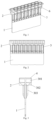
Fig. 1 is a schematic structural diagram of a micro-column gel card according to the present invention. -
Fig. 2 is a front view of a micro-column gel card according to the present invention. -
Fig. 3 is a left view of a micro-column gel card according to the present invention. -
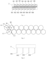
Fig. 4 is a bottom view of a micro-column gel card according to the present invention. -
Fig. 5 is a schematic diagram of equal center-to-center spacing between adjacent tubular columns according toEmbodiment 2 of the present invention. -
Fig. 6 is a schematic diagram of a sample adding mechanism according toEmbodiment 2 of the present invention. -
Fig. 7 is a flow chart of a sample adding method according toEmbodiment 2 of the present invention. -
Fig. 8 is a flow chart of a sample adding method according toEmbodiment 3 of the present invention. - Wherein, 1-lower clamp body, 2-upper clamp body, 3-tubular column, 301-sample adding cavity, 302-reaction cavity, 303-gel column, 4-film-covered column, 5-sample adding mechanism, 501-first sample adding device, 502-second sample adding device, 503-third sample adding device, 504-fourth sample adding device, 6-first reinforcing rib, 7-second reinforcing rib.
- In order that the objects, technical solutions and advantages of the present invention will become more apparent, implementations of the present invention will be described hereinafter with reference to the accompanying drawings. Obviously, the described embodiments are only a part of the embodiments of the present invention, rather than all the embodiments. Based on the embodiments of the present invention, all other embodiments obtained by those of ordinary skill in the art without creative work shall fall within the scope of the present invention.
- It should be noted that all directional indicators (for example, up, down, left, right, front, rear, and the like) in the embodiments of the present invention are only used to explain relative positional relationships, motion conditions and the like between components in a particular pose. If the particular pose changes, the directional indicator changes accordingly.
- As shown in
Figs. 1 to 3 , a micro-column gel card includes a fixing plate and a plurality oftubular columns 3 arranged and fixed through the fixing plate. The tubular columns are fixed to two sides of the fixing plate respectively, and the tubular columns located on the two sides of the fixing plate are arranged in a staggered manner. Anytubular column 3 includes asample adding cavity 301, areaction cavity 302, and agel column 303. Thegel column 303 is configured to load a gel reagent. Thesample adding cavity 301 is provided above thegel column 303. Thereaction cavity 302 is connected between thesample adding cavity 301 and thegel column 303. A central axis of thesample adding cavity 301 and a central axis of thegel column 303 do not coincide. - There is a certain staggered relationship between the tubular columns distributed on two sides of the fixing plate, and any two adjacent tubular columns do not overlap, so as to ensure that the interference of interpretation between the tubular columns in the instrumental interpretation of each gel column when the micro-column gel card is used in a micro-column gel experiment is reduced. In addition, when performing the micro-column gel experiment, it is necessary to first add a sample/reagent for a sufficient reaction. In order to prevent the sample/reagent from being directly injected into the gel column, it is usually necessary to inject the sample/reagent into the reaction cavity for a sufficient reaction, and then the sample/reagent is allowed to settle into the gel column through a tube wall under the action of centrifugal force. Then, the result is interpreted. However, in the existing micro-column gel cards, the sample adding cavity and the gel column are generally of a concentric design, and an operator needs to perform an appropriate offset step number based on the center of the sample adding cavity when debugging the sample adding position, whereby the sample/reagent can be filled into the reaction cavity. The specific offset can only be adjusted according to the experience of the operator. Different operators cannot keep consistent with a preset offset, resulting in uneven and poor consistency of the sample adding positions debugged by different operators. In this technical solution, the central axis of the sample adding cavity and the central axis of the gel column do not coincide. That is, there is an eccentric design between the sample adding cavity of each tubular column and the gel column. When debugging the sample adding position, the operator only needs to debug the sample adding position based on a central position of the sample adding cavity (that is, the central axis of the sample adding cavity), which can ensure the consistency of sample adding positions adjusted by different operators to a certain extent.
- As shown in
Figs. 2 and4 , in one embodiment, the two sides of the fixing plate are provided with an equal number (eight) of tubular columns, so as to form a double-row sixteen-pore micro-column gel card. The tubular columns on the two sides of the fixing plate are in a centrosymmetric form. Vertical projections of the gel column and the sample adding cavity are internally tangent. Any two gel columns are parallel to each other and front projections do not overlap. The tubular columns on one side of the fixing plate are set to a first tubular column group (a column group located at the upper row shown inFig. 4 is the first tubular column group), and the tubular columns on the other side are set to a second tubular column group (a column group located at the lower row shown inFig. 4 is the first tubular column group). As shown inFig. 4 , the eight tubular columns in the first tubular column group are set to H1-H8 respectively, and the eight tubular columns in the second tubular column group are set to M1-M8 respectively. The center-to-center spacing between any two adjacent tubular columns is equal. A staggered spacing between the first tubular column group and the second tubular column group is one-half of the center-to-center spacing between adjacent tubular columns. In addition to ensuring that there is no overlap between adjacent gel columns, the lateral dimension of the whole micro-column gel card can be reduced to a large extent, and the space utilization can be improved. The two groups of tubular columns are in a centrosymmetric form, thereby ensuring that the micro-column gel card may be placed in automated equipment along all directions, and reducing the error rate during an actual operation. The center-to-center spacing between adjacent tubular columns is set to d. As shown inFig. 4 , the staggered spacing between H1 and M1, H2 and M2, H3 and M3, H4 and M4, H5 and M5, H6 and M6, H7 and M7, and H8 and M8 are all one-half of the center-to-center spacing between adjacent tubular columns, that is, d/2. - In this embodiment, the
sample adding mechanism 5 has a freedom of motion in X, Y, and Z directions. Thesample adding mechanism 5 includes four sample adding devices (Fig. 6 shows a corresponding schematic diagram, and it should be noted thatFig. 6 is a schematic diagram drawn for explaining the technical effect of this embodiment, and does not represent an actual structural relationship), which are a firstsample adding device 501, a secondsample adding device 502, a thirdsample adding device 503 and a fourthsample adding device 504, respectively. A distance between any two adjacent sample adding devices is a center-to-center spacing between adjacent tubular columns, that is, 2d. The sample adding mechanism adopts a sample adding method for the double-row sixteen-pore micro-column gel card in this embodiment as shown inFig. 7 : - S1: The sample adding mechanism is moved above the micro-column gel card.
- S2: One side of the edge of the fixing plate is set to a first direction and the other side is set to a second direction.
- As shown in
Fig. 4 , a left side of the fixing plate is set to the first direction and a right side of the fixing plate is set to the second direction. - S3: The sample adding mechanism is moved until any of sample adding devices on two sides is located above a central axis position of a sample adding cavity of a tubular column near the first direction or the second direction of the edge of the fixing plate in the first tubular column group or the second tubular column group.
- As shown in
Fig. 4 , for example, in one implementation, the sample adding mechanism is moved until the firstsample adding device 501 is located above a central axis position of a sample adding cavity of a tubular column H1 in the first tubular column group. - S4: The sample adding mechanism completes sample adding on four tubular columns, such as H1, H3, H5, and H7, in the first tubular column group through the first to fourth sample adding devices.
- S5: The sample adding mechanism is horizontally moved to a first set direction by a distance of d, so as to complete sample adding on the remaining four tubular columns (that is, tubular columns H2, H4, H6, and H8) in the first tubular column group.
- The first set direction is selected as: when the sample-added tubular column near the edge of the fixing plate in the first tubular column group or the second tubular column group is located in the first direction of the fixing plate, the set direction is the second direction, or when the sample-added tubular column near the edge of the fixing plate in the first tubular column group or the second tubular column group is located in the second direction of the fixing plate, the set direction is the first direction.
- In this embodiment, the first direction is the left side of the fixing plate, and the second direction is the right side of the fixing plate (certainly, it is also possible to set the right side of the fixing plate to the first direction and the left side of the fixing plate to the second direction, which both fall within the scope of the present invention). The sample-added tubular column near the edge of the fixing plate in the first tubular column group is a tubular column H1. The tubular column H1 is located on the left side of the fixing plate, which is the first direction. Therefore, the first set direction is an opposite direction thereto, and the first set direction is the second direction, which is the right side of the fixing plate. Then the sample adding mechanism is horizontally moved to the right side of the fixing plate or the second direction by a distance of d, so as to complete sample adding on the remaining four tubular columns (that is, tubular columns H2, H4, H6, and H8) in the first tubular column group.
- S6: The sample adding mechanism is selectively horizontally moved to a second set direction by a distance that is one-half or three-seconds of d. Then, the sample adding mechanism is moved towards the second tubular column group by a set distance along a Y direction, whereby the sample adding device near the edge of the fixing plate in the sample adding mechanism is located above the central axis position of the sample adding cavity of the corresponding tubular column, and the sample adding mechanism completes sample adding on N/2 tubular columns in the second tubular column group or the first tubular column group.
- In this embodiment, when sample adding on the eight tubular columns in the first tubular column group is completed, the first to fourth sample adding devices are respectively located above the four tubular columns H2, H4, H6, and H8 in the first tubular column group. Next, sample adding is required on the second tubular column group. The sample adding mechanism is horizontally moved to a second set direction by a distance that is three-seconds of d. In this case, the second set direction is the left side of the fixing plate. Then, the sample adding mechanism is moved towards the second tubular column group by a set distance along a Y direction. The set distance in this embodiment is the distance in the Y direction between the centers of the tubular columns H1 and M1, whereby the sample adding device near the edge of the fixing plate in the sample adding mechanism is located above the central axis position of the sample adding cavity of the corresponding tubular column. That is, the first
sample adding device 501 is located above the central axis position of the sample adding cavity of the tubular column M1 in the second tubular column group. Then, the sample adding mechanism completes sample adding on four tubular columns M1, M3, M5, and M7 in the second tubular column group. - S7: The sample adding mechanism is horizontally moved to a third set direction of the edge of the fixing plate by a distance of d, so as to complete sample adding on four tubular columns M2, M4, M6, and M8 in the second tubular column group.
- The third set direction is selected as: when the sample-added tubular column near the edge of the fixing plate in the second tubular column group is located in the first direction of the fixing plate, the set direction is the second direction, or when the sample-added tubular column near the edge of the fixing plate in the second tubular column group or the first tubular column group is located in the second direction of the fixing plate, the set direction is the first direction.
- In this embodiment, the sample-added tubular column near the edge of the fixing plate in the second tubular column group is a tubular column M1. The tubular column M1 is located on the left side of the fixing plate, which is the first direction. Therefore, the third set direction is an opposite direction thereto, and the third set direction is the second direction, which is the right side of the fixing plate. Then the sample adding mechanism is horizontally moved to the right side of the fixing plate or the second direction by a distance of d, so as to complete sample adding on the remaining four tubular columns (that is, tubular columns M2, M4, M6, and M8) in the second tubular column group.
- In the solution of this embodiment, the sample adding mechanism performs sample adding in a staggered manner on the foregoing micro-column gel card according to the sample adding method, which can greatly avoid interference of simultaneous sample adding between adjacent tubular columns or possible cross-contamination problems, and the like.
- In addition, in the solution of this embodiment, the center-to-center spacing between any two adjacent tubular columns is equal. That is, the center-to-center spacing between adjacent tubular columns on the same side of the fixing plate and the center-to-center spacing between adjacent tubular columns on different sides of the fixing plate are all equal, whereby the centers of three adjacent tubular columns on the two sides of the fixing plate are connected to form an equilateral triangle (
Fig. 5 shows a corresponding schematic diagram, and it should be noted thatFig. 5 is a schematic diagram drawn for explaining the technical effect of this embodiment, and does not represent an actual structural relationship). As shown inFig. 4 , the center-to-center spacing of H1, M1, and M2 is equal, and the center-to-center spacing of H1, H2, and M2 is also equal, and so on. One-by-one descriptions will be omitted herein. A specific relationship is maintained between displacement distances of the sample adding device in different tubular columns and the center-to-center spacing between adjacent tubular columns when the micro-column gel card is placed in an automated instrument to perform an experiment, thereby simplifying logic control. That is, when the placement position of the micro-column gel card is offset or when the sample adding device is out of step, the offset of all pore positions is consistent, and the relative offset and offset range of the sample adding position are also consistent. That is, if the sample adding position is not readjusted, the position range of sample injection points on the reaction cavity of each tubular column relative to the reaction cavity is kept consistent under the displacement distance originally set. When the placement position of the micro-column gel card is offset, if the sample injection points of the sample adding device on a reaction cavity of a certain tubular column are still located within the range of the reaction cavity, it may be concluded that the sample injection points of all the tubular columns are located within the range of the reaction cavity, and it may be properly considered that the sample adding position is not readjusted. When the sample adding position needs to be adjusted, it is only necessary to use a tubular column as a sample adding position adjustment object. Specifically, as shown in the schematic diagram ofFig. 5 , the sample injection points of three tubular columns shown in the diagram should be points A1, B1, and C1. When the positions of the sample injection points are offset to points A2, B2, and C2, the position ranges of points A2, B2, and C2 relative to the reaction cavities of the respective tubular columns are consistent. As shown inFig. 5 , the offset position ranges of points A2, B2, and C2 relative to the reaction cavities of the respective tubular columns are approximately 15° in a horizontal direction and the distances to the outer walls of the reaction cavities are also consistent, which all fall within the position ranges of the reaction cavities of the respective columns without exceeding. - In this embodiment, the
sample adding mechanism 5 has a freedom of motion in X, Y, and Z directions. Thesample adding mechanism 5 includes four sample adding devices (Fig. 6 shows a corresponding schematic diagram, and it should be noted thatFig. 6 is a schematic diagram drawn for explaining the technical effect of this embodiment, and does not represent an actual structural relationship), which are a firstsample adding device 501, a secondsample adding device 502, a thirdsample adding device 503 and a fourthsample adding device 504, respectively. A distance between any two adjacent sample adding devices is a center-to-center spacing between adjacent tubular columns, that is, 2d. The sample adding mechanism adopts a sample adding method for the double-row sixteen-pore micro-column gel card in this embodiment as shown inFig. 8 . - S8: The sample adding mechanism is moved above the micro-column gel card.
- S9: One side of the edge of the fixing plate is set to a first direction and the other side is set to a second direction.
- As shown in
Fig. 4 , a left side of the fixing plate is set to the first direction and a right side of the fixing plate is set to the second direction. - S10: The sample adding mechanism is moved until any of sample adding devices on two sides is located above a central axis position of a sample adding cavity of a tubular column near the first direction or the second direction of the edge of the fixing plate in the first tubular column group or the second tubular column group.
- As shown in
Figs. 4 and 5 , in this embodiment, the sample adding mechanism is moved until the fourthsample adding device 504 is located above a central axis position of a sample adding cavity of a tubular column H8 in the first tubular column group. - S11: The sample adding mechanism completes sample adding on four tubular columns H2, H4, H6, and H8 in the first tubular column group through the first to fourth sample adding devices.
- S12: The sample adding mechanism is horizontally moved to a first set direction by a distance of d, so as to complete sample adding on the remaining four tubular columns (that is, tubular columns H1, H3, H5, and H7) in the first tubular column group.
- The first set direction is selected as: when the sample-added tubular column near the edge of the fixing plate in the first tubular column group or the second tubular column group is located in the first direction of the fixing plate, the set direction is the second direction, or when the sample-added tubular column near the edge of the fixing plate in the first tubular column group or the second tubular column group is located in the second direction of the fixing plate, the set direction is the first direction.
- In this embodiment, the first direction is the left side of the fixing plate, and the second direction is the right side of the fixing plate (certainly, it is also possible to set the right side of the fixing plate to the first direction and the left side of the fixing plate to the second direction, which both fall within the scope of the present invention). The sample-added tubular column near the edge of the fixing plate in the first tubular column group is a tubular column H8. The tubular column H8 is located on the right side of the fixing plate, which is the second direction. Therefore, the first set direction is an opposite direction thereto, and the first set direction is the first direction, which is the left side of the fixing plate. Then the sample adding mechanism is horizontally moved to the left side of the fixing plate or the first direction by a distance of d, so as to complete sample adding on the remaining four tubular columns (that is, tubular columns H1, H3, H5, and H7) in the first tubular column group.
- S13: The sample adding mechanism is selectively horizontally moved to a second set direction by a distance that is one-half or three-seconds of d. Then, the sample adding mechanism is moved towards the second tubular column group by a set distance along a Y direction, whereby the sample adding device near the edge of the fixing plate in the sample adding mechanism is located above the central axis position of the sample adding cavity of the corresponding tubular column, and the sample adding mechanism completes sample adding on N/2 tubular columns in the second tubular column group or the first tubular column group.
- In this embodiment, when sample adding on the eight tubular columns in the first tubular column group is completed, the first to fourth sample adding devices are respectively located above the four tubular columns H1, H3, H5, and H7 in the first tubular column group. Next, sample adding is required on the second tubular column group. The sample adding mechanism is horizontally moved to a second set direction by a distance that is one-half of d. In this case, the second set direction is the left side of the fixing plate. Then, the sample adding mechanism is moved towards the second tubular column group by a set distance along a Y direction. The set distance in this embodiment is the distance in the Y direction between the centers of the tubular columns H1 and M1, whereby the sample adding device near the edge of the fixing plate in the sample adding mechanism is located above the central axis position of the sample adding cavity of the corresponding tubular column. That is, the first
sample adding device 501 is located above the central axis position of the sample adding cavity of the tubular column M1 in the second tubular column group. Then, the sample adding mechanism completes sample adding on four tubular columns M1, M3, M5, and M7 in the second tubular column group. - S14: The sample adding mechanism is horizontally moved to a third set direction of the edge of the fixing plate by a distance of d, so as to complete sample adding on four tubular columns M2, M4, M6, and M8 in the second tubular column group.
- The third set direction is selected as: when the sample-added tubular column near the edge of the fixing plate in the second tubular column group is located in the first direction of the fixing plate, the set direction is the second direction, or when the sample-added tubular column near the edge of the fixing plate in the second tubular column group or the first tubular column group is located in the second direction of the fixing plate, the set direction is the first direction.
- In this embodiment, the sample-added tubular column near the edge of the fixing plate in the second tubular column group is a tubular column M1. The tubular column M1 is located on the left side of the fixing plate, which is the first direction. Therefore, the third set direction is an opposite direction thereto, and the third set direction is the second direction, which is the right side of the fixing plate. Then the sample adding mechanism is horizontally moved to the right side of the fixing plate or the second direction by a distance of d, so as to complete sample adding on the remaining four tubular columns (that is, tubular columns M2, M4, M6, and M8) in the second tubular column group.
- In other embodiments of S10, the sample adding mechanism may be moved first until the first
sample adding device 501 is located above the central axis position of the sample adding cavity of the tubular column M1 or M8 in the second tubular column group, and the sample adding method thereof is similar toEmbodiments - As described in
Embodiment 2, the eight tubular columns in the first tubular column group are set to H1-H8, respectively, and the eight tubular columns in the second tubular column group are set to M1-M8, respectively. In this embodiment, as shown inFigs. 1 to 3 , the fixing plate includes alower clamp body 1 and anupper clamp body 2. A minimum distance between edges of the sample adding cavities of the tubular columns on both sides of the first tubular column group and the second tubular column group and an edge of the upper clamp body is 1-3 mm. That is, the minimum distance between edges of the sample adding cavities of the tubular columns M1, H1, M8, and H8 and an edge of theupper clamp body 2 is 1-3 mm. By limiting the distance between the edges of the sample adding cavities of the tubular columns on the two sides and the edge of the fixing plate, it is convenient for a gripper of automated equipment to grasp the micro-column gel card while improving the space utilization. If the distance between the edges of the sample adding cavities of the tubular columns on the two sides and the edge of the fixing plate is too large, the size of the whole micro-column gel card is large, and the space utilization is low. If the distance between the edges of the sample adding cavities of the tubular columns on the two sides and the edge of the fixing plate is too small, the gripper of the automated equipment may have the problems of unstable grasping and falling when grasping the micro-column gel card. - In this embodiment, the sample adding mechanism includes sixteen sample adding devices (not shown) in a distribution and arrangement form adapted to a distribution and arrangement form of double-row sixteen tubular columns on the micro-column gel card. The sample adding mechanism has a freedom of motion in X, Y, and Z directions. The sample adding mechanism may complete the sample adding process for each tubular column on the foregoing micro-column gel card at once, thereby greatly improving working efficiency.
- In an embodiment, the micro-column gel card further includes a sealing layer. A film-covered
column 4 is provided at an opening of the sample adding cavity. The film-covered column is of an annular bulged structure. An inner ring step (not shown) is provided on an inner side wall of the film-covered column. The sealing layer is in sealing connection with the film-covered column. A sealing material (such as environment friendly glue) used in sealing usually has a certain fluidity. By providing the inner ring step on the inner side wall of the film-covered column, it can be ensured that the sealing material has a certain flow space and is capable of flowing to the inner ring step without overflowing outside the sampling cavity, so as to ensure that the sealing material between the sealing layer and the film-covered column is sufficient for good adhesion. - In an embodiment, a first reinforcing
rib 6 is provided outside the sample adding cavity of each of the tubular columns, and a second reinforcingrib 7 is provided outside the gel column of each tubular column. The first reinforcing rib and the second reinforcing rib are provided in order to make the micro-column gel card more stable structurally and less deformable. - In an embodiment, the
sample adding cavity 301 has an outer diameter of 8-10 mm, thegel column 303 has an outer diameter of 2-4 mm and an inner diameter of 1-1.5 mm, thereaction cavity 302 has a depth of 3-6 mm, and the gel column has a depth of 15-20 mm. The reaction effect of samples/reagents in the reaction cavity is effectively improved by controlling the ratio of pore sizes of the sample adding cavity and the gel column and the depth of the reaction cavity. When the ratio of the pore sizes of the sample adding cavity and the gel column is larger or the depth of the reaction cavity is smaller, the inclination of a conical surface of the reaction cavity is smaller, the samples/reagents are not easily spread and dispersed, and the reaction effect is affected. - The applicant hereby states that the above-described embodiments are merely illustrative of the basic principles, principal features and advantages of the present invention. It will be understood by those skilled in the art that the present invention is not limited to the foregoing embodiments. The foregoing embodiments and the specification are merely illustrative of the principles of the present invention. Those of ordinary skill in the art may also make various changes and modifications without departing from the scope of the present invention. which is defined by the appended claims.
Claims (15)
- A micro-column gel card, comprising a fixing plate and a plurality of tubular columns (3, H1-H8, M1-M8) arranged and fixed through the fixing plate,wherein,the any tubular column (3, H1-H8, M1-M8) comprises a sample adding cavity (301), a reaction cavity (302), and a gel column (303);the gel column (303) is configured to load a gel reagent;the sample adding cavity (301) is provided above the gel column (303); andthe reaction cavity (302) is connected between the sample adding cavity (301) and the gel column (303);characterized in that,the tubular columns (3, H1-H8, M1-M8) are fixed to two sides of the fixing plate respectively, and the tubular columns (3, H1-H8, M1-M8) located on the two sides of the fixing plate are arranged in a staggered manner; anda central axis of the sample adding cavity (301) and a central axis of the gel column (303) do not coincide.
- The micro-column gel card according to claim 1, characterized in that: the tubular columns (3, H1-H8, M1-M8) on the two sides of the fixing plate are in a centrosymmetric form.
- The micro-column gel card according to claim 2, characterized in that: a center-to-center spacing between any two adjacent tubular columns (3, H1-H8, M1-M8) among the tubular columns (3, H1-H8, M1-M8) is equal.
- The micro-column gel card according to claim 3, characterized in that: the center-to-center spacing between any two adjacent tubular columns (3, H1-H8, M1-M8) among the tubular columns (3, H1-H8, M1-M8) is 9 mm.
- The micro-column gel card according to claim 3, characterized in that: vertical projections of the gel column (303) and the sample adding cavity (301) are internally tangent.
- The micro-column gel card according to claim 5, characterized in that: any two gel columns (303) are parallel to each other and front projections do not overlap.
- The micro-column gel card according to claim 1, characterized by: further comprising a sealing layer, wherein a film-covered column (4) is provided at an opening of the sample adding cavity (301), the film-covered column (4) is of an annular bulged structure, an inner ring step is provided on an inner side wall of the film-covered column (4), and the sealing layer is in sealing connection with the film-covered column (4).
- The micro-column gel card according to claim 1, characterized in that: a first reinforcing rib (6) is provided outside the sample adding cavity (301) of each of the tubular columns (3, H1-H8, M1-M8), and a second reinforcing rib (7) is provided outside the gel column (303) of each tubular column (3, H1-H8, M1-M8).
- The micro-column gel card according to claim 1, characterized in that: the sample adding cavity (301) has an outer diameter of 8-10 mm, the gel column (303) has an outer diameter of 2-4 mm and an inner diameter of 1-1.5 mm, the reaction cavity (302) has a depth of 3-6 mm, and the gel column (303) has a depth of 15-20 mm.
- The micro-column gel card according to claim 6, characterized in that: the two sides of the fixing plate are provided with an equal number of tubular columns (3, H1-H8, M1-M8), the tubular columns (3, H1-H8) on one side of the fixing plate are set to a first tubular column group (3, H1-H8), the tubular columns (3, M1-M8) on the other side are set to a second tubular column group (3, M1-M8), and a staggered spacing between the first tubular column group (3, H1-H8) and the second tubular column group (3, M1-M8) is one-half of the center-to-center spacing between adjacent tubular columns (3, H1-H8, M1-M8).
- The micro-column gel card according to claim 10, characterized in that: the fixing plate comprises a lower clamp body (1) and an upper clamp body (2), and a minimum distance between edges of the sample adding cavities (301) of the tubular columns (3, H1-H8, M1-M8) on both sides of the first tubular column group (3, H1-H8) and the second tubular column group (3, M1-M8) and an edge of the upper clamp body (2) is 1-3 mm.
- The micro-column gel card according to any one of claims 10 or 11, characterized in that: the first tubular column group (3, H1-H8) and the second tubular column group (3, M1-M8) each comprise N tubular columns (3, H1-H8, M1-M8), N being a natural number of not less than 4 and N being an even number.
- A combination of the micro-column gel card according to any one of claims 1 to 12 and a sample adding mechanism (5) configured for sample adding thereon, wherein the sample adding mechanism (5) comprises a plurality of sample adding devices (501, 502, 503, 504) in a distribution and arrangement form adapted to a distribution and arrangement form of tubular columns (3, H1-H8, M1-M8) on the micro-column gel card, and the sample adding mechanism (5) has a freedom of motion in X, Y, and Z directions.
- The combination of claim 13, characterized in that the sample adding mechanism (5) comprises N/2 sample adding devices (501, 502, 503, 504), a distance between any two adjacent sample adding devices (501, 502, 503, 504) is twice a center-to-center spacing between adjacent tubular columns (3, H1-H8, M1-M8).
- A sample adding method for a sample adding mechanism (5), characterized by comprising:moving the sample adding mechanism (5) above the micro-column gel card according to any one of claims 1 to 12;setting one side of the edge of the fixing plate to a first direction and the other side to a second direction;moving the sample adding mechanism (5) until any of sample adding devices on two sides is located above a central axis position of a sample adding cavity (301) of a tubular column (3, H1-H8, M1-M8) near the first direction or the second direction of the edge of the fixing plate in the first tubular column group (3, H1-H8) or the second tubular column group (3, M1-M8);completing, by the sample adding mechanism (5), sample adding on N/2 tubular columns in the first tubular column group (3, H1-H8) or the second tubular column group (3, M1-M8) through N/2 sample adding devices (501, 502, 503, 504);horizontally moving the sample adding mechanism (5) to a first set direction by a distance that is equal to one center-to-center spacing between adjacent tubular columns (3, H1-H8, M1-M8), so as to complete sample adding on the remaining N/2 tubular columns in the first tubular column group (3, H1-H8) or the second tubular column group (3, M1-M8),wherein the first set direction is selected as: when the sample-added tubular column near the edge of the fixing plate in the first tubular column group (3, H1-H8) or the second tubular column group (3, M1-M8) is located in the first direction of the fixing plate, the first set direction is the second direction, or when the sample-added tubular column near the edge of the fixing plate in the first tubular column group (3, H1-H8) or the second tubular column group (3, M1-M8) is located in the second direction of the fixing plate, the first set direction is the first direction;selectively horizontally moving the sample adding mechanism (5) to a second set direction by a distance that is one-half or three-seconds of the center-to-center spacing between adjacent tubular columns (3, H1-H8, M1-M8), then moving the sample adding mechanism (5) towards the second tubular column group (3, M1-M8) or the first tubular column group (3, H1-H8) by a set distance along a Y direction, whereby the sample adding device near the edge of the fixing plate in the sample adding mechanism (5) is located above the central axis position of the sample adding cavity (301) of the corresponding tubular column, and the sample adding mechanism (5) completes sample adding on N/2 tubular columns in the second tubular column group (3, M1-M8) or the first tubular column group (3, H1-H8); andhorizontally moving the sample adding mechanism (5) to a third set direction of the edge of the fixing plate by a distance that is equal to one center-to-center spacing between adjacent tubular columns (3, H1-H8, M1-M8), so as to complete sample adding on the remaining N/2 tubular columns in the second tubular column group (3, M1-M8) or the first tubular column group (3, H1-H8),wherein the third set direction is selected as: when the sample-added tubular column near the edge of the fixing plate in the second tubular column group (3, M1-M8) or the first tubular column group (3, H1-H8) is located in the first direction of the fixing plate, the third set direction is the second direction, or when the sample-added tubular column near the edge of the fixing plate in the second tubular column group (3, M1-M8) or the first tubular column group (3, H1-H8) is located in the second direction of the fixing plate, the third set direction is the first direction.
Applications Claiming Priority (2)
| Application Number | Priority Date | Filing Date | Title |
|---|---|---|---|
| CN202210034981.6A CN114295852B (en) | 2022-01-13 | 2022-01-13 | Microcolumn gel card, sampling mechanism and method |
| PCT/CN2022/080452 WO2023133998A1 (en) | 2022-01-13 | 2022-03-11 | Microcolumn gel card, and sample adding mechanism and method |
Publications (4)
| Publication Number | Publication Date |
|---|---|
| EP4235182A1 EP4235182A1 (en) | 2023-08-30 |
| EP4235182A4 EP4235182A4 (en) | 2024-04-10 |
| EP4235182B1 true EP4235182B1 (en) | 2025-06-04 |
| EP4235182C0 EP4235182C0 (en) | 2025-06-04 |
Family
ID=80976963
Family Applications (1)
| Application Number | Title | Priority Date | Filing Date |
|---|---|---|---|
| EP22871110.7A Active EP4235182B1 (en) | 2022-01-13 | 2022-03-11 | Microcolumn gel card, and sample adding mechanism and method |
Country Status (4)
| Country | Link |
|---|---|
| US (1) | US12564839B2 (en) |
| EP (1) | EP4235182B1 (en) |
| CN (1) | CN114295852B (en) |
| WO (1) | WO2023133998A1 (en) |
Family Cites Families (17)
| Publication number | Priority date | Publication date | Assignee | Title |
|---|---|---|---|---|
| EP1547691A1 (en) * | 2003-12-22 | 2005-06-29 | F. Hoffmann-La Roche Ag | Microtiter plate, system and method for processing samples |
| JP2008224318A (en) * | 2007-03-09 | 2008-09-25 | Olympus Corp | Multilayered flocculation determining container |
| US8187538B2 (en) * | 2008-01-17 | 2012-05-29 | Ortho-Clinical Diagnostics, Inc. | Diluent wells produced in card format for immunodiagnostic testing |
| CN102281949B (en) * | 2008-12-23 | 2014-10-22 | 新彼奥医疗系统公司 | Device and analyzing system for conducting agglutination assays |
| CN103063853B (en) * | 2011-10-20 | 2016-04-13 | 苏州市锦新医用塑料容器厂 | A kind of blood type reagent card |
| CN203310840U (en) * | 2012-12-24 | 2013-11-27 | 上海血液生物医药有限责任公司 | Micro-column gel card |
| CN103163310A (en) * | 2013-03-15 | 2013-06-19 | 东南大学 | Multi-channel micro-volume sampling device |
| CN105515176A (en) | 2013-04-15 | 2016-04-20 | 朱海燕 | Switch cabinet for power system and working method thereof |
| CN105974147B (en) * | 2016-07-01 | 2018-04-10 | 江苏克莱斯克生物技术有限公司 | Blood group serology automatic detection all-in-one |
| CN109342736A (en) * | 2018-10-17 | 2019-02-15 | 深圳市龙华区中心医院 | A microcolumn agglutination anti-human globulin detection card |
| CN109853045B (en) * | 2018-12-03 | 2023-10-24 | 江苏苏博生物医学科技南京有限公司 | Gene chip for high-flux detection |
| CN109939758A (en) * | 2019-03-28 | 2019-06-28 | 上海市嘉定区中心医院 | An automatic blood pretreatment and pipetting platform for blood rheology detection |
| CN210815316U (en) * | 2019-05-20 | 2020-06-23 | 中国科学院苏州生物医学工程技术研究所 | Micro-pillar chip card |
| CN212275783U (en) * | 2020-06-05 | 2021-01-01 | 上海润普生物技术有限公司 | Anti-human globulin card for cross matching detection |
| GB2597505A (en) * | 2020-07-24 | 2022-02-02 | The Francis Crick Institute Ltd | Tip ejector block and multi-channel laboratory tool |
| TR2021013441U5 (en) * | 2021-08-25 | 2021-12-21 | Dia Pro Tibbi Ueruenler Sanayi Ve Ticaret Anonim Sirketi | Blood grouping test. |
| CN216900589U (en) * | 2022-01-13 | 2022-07-05 | 深圳市爱康生物科技股份有限公司 | A kind of micro-column gel card and sample adding mechanism |
-
2022
- 2022-01-13 CN CN202210034981.6A patent/CN114295852B/en active Active
- 2022-03-11 EP EP22871110.7A patent/EP4235182B1/en active Active
- 2022-03-11 US US18/258,722 patent/US12564839B2/en active Active
- 2022-03-11 WO PCT/CN2022/080452 patent/WO2023133998A1/en not_active Ceased
Also Published As
| Publication number | Publication date |
|---|---|
| EP4235182A4 (en) | 2024-04-10 |
| US20240375110A1 (en) | 2024-11-14 |
| US12564839B2 (en) | 2026-03-03 |
| WO2023133998A1 (en) | 2023-07-20 |
| CN114295852A (en) | 2022-04-08 |
| EP4235182C0 (en) | 2025-06-04 |
| CN114295852B (en) | 2025-08-15 |
| EP4235182A1 (en) | 2023-08-30 |
Similar Documents
| Publication | Publication Date | Title |
|---|---|---|
| US6869792B2 (en) | Method and apparatus for performing multiple processing steps on a sample in a single vessel | |
| WO2018014513A1 (en) | Microfluidic reagent card and detection method and application thereof | |
| CN217025973U (en) | Organoid construction workstation | |
| JPH0130418B2 (en) | ||
| US20160045883A1 (en) | Stabilisation features | |
| US20160144507A1 (en) | Operation command generation device, operation command generation method, non-transitory computer readable storage medium, and process system | |
| US9678094B2 (en) | Apparatus and method for determining the position of an automatically displaceable gauge | |
| WO2025001220A1 (en) | Multi-task parallel nucleic acid extraction and conversion method and apparatus | |
| EP4235182A1 (en) | Microcolumn gel card, and sample adding mechanism and method | |
| JP2020505597A (en) | Systems, methods and sample carriers for assays | |
| CN107660269B (en) | Rods, kits and methods of use thereof for multiplex analyte detection, enrichment or purification | |
| CN116474848A (en) | Electrochemical microfluidic chip and nucleic acid detection method | |
| CN113853441A (en) | Devices, systems and methods for fluid delivery for sequencing | |
| Li et al. | Microfluidic triple-gradient generator for efficient screening of chemical space | |
| EP4420781A1 (en) | Electrowetting-based concentration homogenization microfluidic chip and concentration homogenization method | |
| WO2020208629A1 (en) | Multiplexed array of nanoliter droplet array devices | |
| CN207913815U (en) | Pipettor gun head | |
| CN208420822U (en) | Titer determination device and virus infectivity detection device | |
| TWM632682U (en) | Blood grouping test | |
| CN205443265U (en) | Sample reaction unit | |
| CN211235559U (en) | Card type micro test tube reaction cup | |
| CN109603951A (en) | Pipe support | |
| CN209885874U (en) | Test-tube rack for analytical chemistry laboratory | |
| JP7848245B2 (en) | Liquid mixing using an automated liquid handling system | |
| CN223513001U (en) | Culture dish for oocyte/early embryo immunofluorescence staining |
Legal Events
| Date | Code | Title | Description |
|---|---|---|---|
| STAA | Information on the status of an ep patent application or granted ep patent |
Free format text: STATUS: UNKNOWN |
|
| STAA | Information on the status of an ep patent application or granted ep patent |
Free format text: STATUS: THE INTERNATIONAL PUBLICATION HAS BEEN MADE |
|
| PUAI | Public reference made under article 153(3) epc to a published international application that has entered the european phase |
Free format text: ORIGINAL CODE: 0009012 |
|
| STAA | Information on the status of an ep patent application or granted ep patent |
Free format text: STATUS: REQUEST FOR EXAMINATION WAS MADE |
|
| 17P | Request for examination filed |
Effective date: 20230330 |
|
| AK | Designated contracting states |
Kind code of ref document: A1 Designated state(s): AL AT BE BG CH CY CZ DE DK EE ES FI FR GB GR HR HU IE IS IT LI LT LU LV MC MK MT NL NO PL PT RO RS SE SI SK SM TR |
|
| A4 | Supplementary search report drawn up and despatched |
Effective date: 20240312 |
|
| RIC1 | Information provided on ipc code assigned before grant |
Ipc: B01L 3/00 20060101ALI20240305BHEP Ipc: G01N 33/80 20060101ALI20240305BHEP Ipc: G01N 35/00 20060101AFI20240305BHEP |
|
| GRAP | Despatch of communication of intention to grant a patent |
Free format text: ORIGINAL CODE: EPIDOSNIGR1 |
|
| STAA | Information on the status of an ep patent application or granted ep patent |
Free format text: STATUS: GRANT OF PATENT IS INTENDED |
|
| DAV | Request for validation of the european patent (deleted) | ||
| DAX | Request for extension of the european patent (deleted) | ||
| INTG | Intention to grant announced |
Effective date: 20250114 |
|
| RIC1 | Information provided on ipc code assigned before grant |
Ipc: B01L 3/00 20060101ALI20250106BHEP Ipc: G01N 33/80 20060101ALI20250106BHEP Ipc: G01N 35/00 20060101AFI20250106BHEP |
|
| GRAS | Grant fee paid |
Free format text: ORIGINAL CODE: EPIDOSNIGR3 |
|
| GRAA | (expected) grant |
Free format text: ORIGINAL CODE: 0009210 |
|
| STAA | Information on the status of an ep patent application or granted ep patent |
Free format text: STATUS: THE PATENT HAS BEEN GRANTED |
|
| AK | Designated contracting states |
Kind code of ref document: B1 Designated state(s): AL AT BE BG CH CY CZ DE DK EE ES FI FR GB GR HR HU IE IS IT LI LT LU LV MC MK MT NL NO PL PT RO RS SE SI SK SM TR |
|
| REG | Reference to a national code |
Ref country code: GB Ref legal event code: FG4D |
|
| REG | Reference to a national code |
Ref country code: CH Ref legal event code: EP |
|
| REG | Reference to a national code |
Ref country code: DE Ref legal event code: R096 Ref document number: 602022015663 Country of ref document: DE |
|
| REG | Reference to a national code |
Ref country code: IE Ref legal event code: FG4D |
|
| U01 | Request for unitary effect filed |
Effective date: 20250630 |
|
| U07 | Unitary effect registered |
Designated state(s): AT BE BG DE DK EE FI FR IT LT LU LV MT NL PT RO SE SI Effective date: 20250704 |
|
| PG25 | Lapsed in a contracting state [announced via postgrant information from national office to epo] |
Ref country code: ES Free format text: LAPSE BECAUSE OF FAILURE TO SUBMIT A TRANSLATION OF THE DESCRIPTION OR TO PAY THE FEE WITHIN THE PRESCRIBED TIME-LIMIT Effective date: 20250604 |
|
| PG25 | Lapsed in a contracting state [announced via postgrant information from national office to epo] |
Ref country code: GR Free format text: LAPSE BECAUSE OF FAILURE TO SUBMIT A TRANSLATION OF THE DESCRIPTION OR TO PAY THE FEE WITHIN THE PRESCRIBED TIME-LIMIT Effective date: 20250905 Ref country code: NO Free format text: LAPSE BECAUSE OF FAILURE TO SUBMIT A TRANSLATION OF THE DESCRIPTION OR TO PAY THE FEE WITHIN THE PRESCRIBED TIME-LIMIT Effective date: 20250904 |
|
| PG25 | Lapsed in a contracting state [announced via postgrant information from national office to epo] |
Ref country code: PL Free format text: LAPSE BECAUSE OF FAILURE TO SUBMIT A TRANSLATION OF THE DESCRIPTION OR TO PAY THE FEE WITHIN THE PRESCRIBED TIME-LIMIT Effective date: 20250604 |
|
| PG25 | Lapsed in a contracting state [announced via postgrant information from national office to epo] |
Ref country code: HR Free format text: LAPSE BECAUSE OF FAILURE TO SUBMIT A TRANSLATION OF THE DESCRIPTION OR TO PAY THE FEE WITHIN THE PRESCRIBED TIME-LIMIT Effective date: 20250604 |
|
| PG25 | Lapsed in a contracting state [announced via postgrant information from national office to epo] |
Ref country code: RS Free format text: LAPSE BECAUSE OF FAILURE TO SUBMIT A TRANSLATION OF THE DESCRIPTION OR TO PAY THE FEE WITHIN THE PRESCRIBED TIME-LIMIT Effective date: 20250904 |
|
| PG25 | Lapsed in a contracting state [announced via postgrant information from national office to epo] |
Ref country code: IS Free format text: LAPSE BECAUSE OF FAILURE TO SUBMIT A TRANSLATION OF THE DESCRIPTION OR TO PAY THE FEE WITHIN THE PRESCRIBED TIME-LIMIT Effective date: 20251004 |
|
| PG25 | Lapsed in a contracting state [announced via postgrant information from national office to epo] |
Ref country code: SM Free format text: LAPSE BECAUSE OF FAILURE TO SUBMIT A TRANSLATION OF THE DESCRIPTION OR TO PAY THE FEE WITHIN THE PRESCRIBED TIME-LIMIT Effective date: 20250604 |
|
| PG25 | Lapsed in a contracting state [announced via postgrant information from national office to epo] |
Ref country code: CZ Free format text: LAPSE BECAUSE OF FAILURE TO SUBMIT A TRANSLATION OF THE DESCRIPTION OR TO PAY THE FEE WITHIN THE PRESCRIBED TIME-LIMIT Effective date: 20250604 |
|
| PG25 | Lapsed in a contracting state [announced via postgrant information from national office to epo] |
Ref country code: SK Free format text: LAPSE BECAUSE OF FAILURE TO SUBMIT A TRANSLATION OF THE DESCRIPTION OR TO PAY THE FEE WITHIN THE PRESCRIBED TIME-LIMIT Effective date: 20250604 |
|
| REG | Reference to a national code |
Ref country code: CH Ref legal event code: U11 Free format text: ST27 STATUS EVENT CODE: U-0-0-U10-U11 (AS PROVIDED BY THE NATIONAL OFFICE) Effective date: 20260401 |
|
| PGFP | Annual fee paid to national office [announced via postgrant information from national office to epo] |
Ref country code: GB Payment date: 20260325 Year of fee payment: 5 |
|
| PLBE | No opposition filed within time limit |
Free format text: ORIGINAL CODE: 0009261 |
|
| STAA | Information on the status of an ep patent application or granted ep patent |
Free format text: STATUS: NO OPPOSITION FILED WITHIN TIME LIMIT |
|
| REG | Reference to a national code |
Ref country code: CH Ref legal event code: L10 Free format text: ST27 STATUS EVENT CODE: U-0-0-L10-L00 (AS PROVIDED BY THE NATIONAL OFFICE) Effective date: 20260416 |
|
| U20 | Renewal fee for the european patent with unitary effect paid |
Year of fee payment: 5 Effective date: 20260325 |
|
| 26N | No opposition filed |
Effective date: 20260305 |