EP4235109B1 - Corps d'épreuve équipé d'un codeur - Google Patents
Corps d'épreuve équipé d'un codeur Download PDFInfo
- Publication number
- EP4235109B1 EP4235109B1 EP23157459.1A EP23157459A EP4235109B1 EP 4235109 B1 EP4235109 B1 EP 4235109B1 EP 23157459 A EP23157459 A EP 23157459A EP 4235109 B1 EP4235109 B1 EP 4235109B1
- Authority
- EP
- European Patent Office
- Prior art keywords
- test body
- rings
- npp
- tracks
- magnetic
- Prior art date
- Legal status (The legal status is an assumption and is not a legal conclusion. Google has not performed a legal analysis and makes no representation as to the accuracy of the status listed.)
- Active
Links
Images

Classifications
-
- G—PHYSICS
- G01—MEASURING; TESTING
- G01D—MEASURING NOT SPECIALLY ADAPTED FOR A SPECIFIC VARIABLE; ARRANGEMENTS FOR MEASURING TWO OR MORE VARIABLES NOT COVERED IN A SINGLE OTHER SUBCLASS; TARIFF METERING APPARATUS; MEASURING OR TESTING NOT OTHERWISE PROVIDED FOR
- G01D5/00—Mechanical means for transferring the output of a sensing member; Means for converting the output of a sensing member to another variable where the form or nature of the sensing member does not constrain the means for converting; Transducers not specially adapted for a specific variable
- G01D5/12—Mechanical means for transferring the output of a sensing member; Means for converting the output of a sensing member to another variable where the form or nature of the sensing member does not constrain the means for converting; Transducers not specially adapted for a specific variable using electric or magnetic means
- G01D5/244—Mechanical means for transferring the output of a sensing member; Means for converting the output of a sensing member to another variable where the form or nature of the sensing member does not constrain the means for converting; Transducers not specially adapted for a specific variable using electric or magnetic means influencing characteristics of pulses or pulse trains; generating pulses or pulse trains
- G01D5/24428—Error prevention
- G01D5/24433—Error prevention by mechanical means
- G01D5/24438—Special design of the sensing element or scale
-
- G—PHYSICS
- G01—MEASURING; TESTING
- G01L—MEASURING FORCE, STRESS, TORQUE, WORK, MECHANICAL POWER, MECHANICAL EFFICIENCY, OR FLUID PRESSURE
- G01L3/00—Measuring torque, work, mechanical power, or mechanical efficiency, in general
- G01L3/02—Rotary-transmission dynamometers
- G01L3/04—Rotary-transmission dynamometers wherein the torque-transmitting element comprises a torsionally-flexible shaft
- G01L3/10—Rotary-transmission dynamometers wherein the torque-transmitting element comprises a torsionally-flexible shaft involving electric or magnetic means for indicating
- G01L3/101—Rotary-transmission dynamometers wherein the torque-transmitting element comprises a torsionally-flexible shaft involving electric or magnetic means for indicating involving magnetic or electromagnetic means
- G01L3/104—Rotary-transmission dynamometers wherein the torque-transmitting element comprises a torsionally-flexible shaft involving electric or magnetic means for indicating involving magnetic or electromagnetic means involving permanent magnets
-
- G—PHYSICS
- G01—MEASURING; TESTING
- G01B—MEASURING LENGTH, THICKNESS OR SIMILAR LINEAR DIMENSIONS; MEASURING ANGLES; MEASURING AREAS; MEASURING IRREGULARITIES OF SURFACES OR CONTOURS
- G01B7/00—Measuring arrangements characterised by the use of electric or magnetic techniques
- G01B7/30—Measuring arrangements characterised by the use of electric or magnetic techniques for measuring angles or tapers; for testing the alignment of axes
-
- G—PHYSICS
- G01—MEASURING; TESTING
- G01D—MEASURING NOT SPECIALLY ADAPTED FOR A SPECIFIC VARIABLE; ARRANGEMENTS FOR MEASURING TWO OR MORE VARIABLES NOT COVERED IN A SINGLE OTHER SUBCLASS; TARIFF METERING APPARATUS; MEASURING OR TESTING NOT OTHERWISE PROVIDED FOR
- G01D5/00—Mechanical means for transferring the output of a sensing member; Means for converting the output of a sensing member to another variable where the form or nature of the sensing member does not constrain the means for converting; Transducers not specially adapted for a specific variable
- G01D5/12—Mechanical means for transferring the output of a sensing member; Means for converting the output of a sensing member to another variable where the form or nature of the sensing member does not constrain the means for converting; Transducers not specially adapted for a specific variable using electric or magnetic means
- G01D5/14—Mechanical means for transferring the output of a sensing member; Means for converting the output of a sensing member to another variable where the form or nature of the sensing member does not constrain the means for converting; Transducers not specially adapted for a specific variable using electric or magnetic means influencing the magnitude of a current or voltage
- G01D5/142—Mechanical means for transferring the output of a sensing member; Means for converting the output of a sensing member to another variable where the form or nature of the sensing member does not constrain the means for converting; Transducers not specially adapted for a specific variable using electric or magnetic means influencing the magnitude of a current or voltage using Hall-effect devices
- G01D5/145—Mechanical means for transferring the output of a sensing member; Means for converting the output of a sensing member to another variable where the form or nature of the sensing member does not constrain the means for converting; Transducers not specially adapted for a specific variable using electric or magnetic means influencing the magnitude of a current or voltage using Hall-effect devices influenced by the relative movement between the Hall device and magnetic fields
-
- G—PHYSICS
- G01—MEASURING; TESTING
- G01D—MEASURING NOT SPECIALLY ADAPTED FOR A SPECIFIC VARIABLE; ARRANGEMENTS FOR MEASURING TWO OR MORE VARIABLES NOT COVERED IN A SINGLE OTHER SUBCLASS; TARIFF METERING APPARATUS; MEASURING OR TESTING NOT OTHERWISE PROVIDED FOR
- G01D5/00—Mechanical means for transferring the output of a sensing member; Means for converting the output of a sensing member to another variable where the form or nature of the sensing member does not constrain the means for converting; Transducers not specially adapted for a specific variable
- G01D5/12—Mechanical means for transferring the output of a sensing member; Means for converting the output of a sensing member to another variable where the form or nature of the sensing member does not constrain the means for converting; Transducers not specially adapted for a specific variable using electric or magnetic means
- G01D5/14—Mechanical means for transferring the output of a sensing member; Means for converting the output of a sensing member to another variable where the form or nature of the sensing member does not constrain the means for converting; Transducers not specially adapted for a specific variable using electric or magnetic means influencing the magnitude of a current or voltage
- G01D5/20—Mechanical means for transferring the output of a sensing member; Means for converting the output of a sensing member to another variable where the form or nature of the sensing member does not constrain the means for converting; Transducers not specially adapted for a specific variable using electric or magnetic means influencing the magnitude of a current or voltage by varying inductance, e.g. by a movable armature
-
- G—PHYSICS
- G01—MEASURING; TESTING
- G01L—MEASURING FORCE, STRESS, TORQUE, WORK, MECHANICAL POWER, MECHANICAL EFFICIENCY, OR FLUID PRESSURE
- G01L3/00—Measuring torque, work, mechanical power, or mechanical efficiency, in general
- G01L3/02—Rotary-transmission dynamometers
- G01L3/04—Rotary-transmission dynamometers wherein the torque-transmitting element comprises a torsionally-flexible shaft
- G01L3/10—Rotary-transmission dynamometers wherein the torque-transmitting element comprises a torsionally-flexible shaft involving electric or magnetic means for indicating
- G01L3/109—Rotary-transmission dynamometers wherein the torque-transmitting element comprises a torsionally-flexible shaft involving electric or magnetic means for indicating involving measuring phase difference of two signals or pulse trains
-
- G—PHYSICS
- G01—MEASURING; TESTING
- G01L—MEASURING FORCE, STRESS, TORQUE, WORK, MECHANICAL POWER, MECHANICAL EFFICIENCY, OR FLUID PRESSURE
- G01L5/00—Apparatus for, or methods of, measuring force, work, mechanical power, or torque, specially adapted for specific purposes
- G01L5/13—Apparatus for, or methods of, measuring force, work, mechanical power, or torque, specially adapted for specific purposes for measuring the tractive or propulsive power of vehicles
Definitions
- the invention relates to a test body equipped with an encoder, a method for producing such a test body and a system for determining a torque comprising such a test body.
- the invention applies in particular to the determination of a torque applied between two rotating members around a geometric axis of rotation, in particular two members integrated into a transmission of a motor torque to a vehicle, for example between the electric motor and the mechanical transmission of an electrically assisted bicycle.
- test body having an inner ring integral in rotation with means for mounting said body on one member, and an outer ring extending around the inner ring while having means for mounting said test body on the other member, said rings being connected by a deformable structure which is arranged to transmit the torque between the members while allowing an angular movement between said rings according to the torque applied between the members.
- a test body can be instrumented with an encoder of a torque determination system comprising a sensor for measuring the angular movement between the rings.
- a similar test body integrated into a torque sensor between two rotating members is known from the document FR-2 774 469 .
- an encoder comprising two rings each carrying a magnetic track capable of emitting a signal representative of the rotational movement of the corresponding ring
- the torque determination system then comprising a sensor having two patterns of sensitive elements arranged at a reading distance from each track to form a signal representative of the angular position of the corresponding ring.
- the document FR-2 821 931 describes the use of a device for comparing such signals which is capable of determining an angle of relative displacement of the rings, and therefore the torque applied in that it induces said angle.
- the invention aims to solve the problems of the prior art by proposing in particular a test body equipped with an encoder comprising two rings each carrying a magnetic track whose possible eccentricity defects make it possible not to affect the precision of the determination of a torque.
- the invention proposes a test body for a system for determining a torque applied between two rotating members about a geometric axis of rotation, said test body having an inner ring integral in rotation with means for mounting said test body on one member, and an outer ring extending around the inner ring while having means for mounting said test body on the other member, said rings being connected by a deformable structure which is arranged to transmit the torque between the members while allowing an angular movement between said rings according to the torque applied between said members, said test body being equipped with two rings each carrying a magnetic track which is capable of emitting a signal representative of the movement of said rotating ring, the rings being fixed on a ring respectively and the magnetic tracks being magnetized concentrically so that they have a common axis of revolution so as to form respectively an inner magnetic track and an outer magnetic track of an encoder.
- the invention proposes a method for producing such a test body, said method providing for fixing the rings on a respective ring and then magnetizing each of the magnetic tracks concentrically so that they have a common axis of revolution.
- the invention proposes a system for determining a torque applied between two rotating members around a geometric axis of rotation, said system comprising a test body according to the second aspect and a sensor comprising a first - respectively a second - pattern of sensitive elements arranged at a reading distance from the inner track - respectively from the outer track - to form a signal representative of the angular position of the corresponding ring, said system further comprising a device for comparing the signals delivered by the sensor, said device being capable of determining an angle between the rings which is a function of the torque applied.
- the system allows the determination of a torque applied between two components integrated in a transmission of engine torque to a vehicle, for example between the electric motor and the mechanical transmission of an electrically assisted bicycle.
- the system comprises a test body having an inner ring 1 integral in rotation with means for mounting said test body on one member, and an outer ring 2 extending around the inner ring 1 while having means for mounting said test body on the other member.
- the rings 1, 2 are connected by a deformable structure which is arranged to transmit the torque between the members while allowing angular movement between said rings as a function of the torque applied between said members.
- the torque transmitted between the shafts induces a torsion of the rings 1, 2 and therefore a relative angular displacement of said rings according to a torsion angle which is a function of said torque, the system determining said torque on the basis of the measurement of said torsion angle.
- an encoder is made with the test body by equipping each of the rings 1, 2 with an inner ring 5 and an outer ring 6 respectively carrying a magnetic track, respectively inner 7 and outer 8, which is capable of emitting a signal, for example periodic, representative of the movement of said rotating ring, the system comprising a sensor for measuring the angular position of each of said rings.
- a succession of respectively Npp i and Npp e pairs of North and South poles 9 is magnetized on a ring 5, 6 to form a multipolar magnetic track 7, 8 capable of emitting a magnetic signal of pseudo-sinusoidal shape.
- the rings 5, 6 may comprise an annular matrix, for example made from a plastic or elastomer material, in which magnetic particles are dispersed, in particular ferrite particles or rare earth particles such as NdFeB, said particles being magnetized to form the magnetic tracks 7, 8.
- the sensor comprises a first - respectively a second - pattern of sensitive elements arranged at a reading distance from the inner track 7 - respectively from the outer track 8 - to form a signal representative of the angular position of the corresponding ring 5, 6.
- each pattern may comprise at least two sensitive elements, in particular a plurality of aligned sensitive elements as described in the documents FR-2 792 403 , EP-2 602 593 And EP-2 602 594 .
- the sensitive elements may be based on a magnetoresistive material whose resistance varies according to the magnetic signal of track 7, 8 to be detected, for example of the AMR, TMR or GMR type, or a Hall effect probe.
- the angular position can be determined incrementally by means of the signal emitted by a magnetic track 7, 8. According to another embodiment, the angular position can be determined absolutely, that is, relative to a reference position, by providing a secondary magnetic track or specific coding on the ring 5, 6.
- the sensors deliver incremental square signals in quadrature
- the comparison device comprising counting means indicating the angular position of each of the rings 5, 6 and subtraction means making it possible to calculate the difference between said angular positions.
- the subtraction means perform for example the operation Npp e .f e .n i - Npp i .f i .n e to calculate the difference between the angular positions of the rings 5, 6.
- the numbers Npp i and Npp e of pairs of poles 9 are such that the poles 9 of the tracks 7, 8 have a polar width which is identical, which provides the advantage of being able to use patterns of sensitive elements with the same configuration and under the same operating conditions. In this way, their errors relative to a magnetic period, for example their non-linearity or other common intrinsic defects, can be compensated.
- the method of producing the encoder involves first fixing the rings 5, 6 on the body, then magnetizing each of the magnetic tracks 7, 8 concentrically so that they have a common axis of revolution P.
- the rings 5, 6 are fixed before their magnetization on respectively a ring 1, 2 of the body to form respectively the inner magnetic track 7 and the outer magnetic track 8 by subsequent magnetization.
- the method provides for concentrically fixing the rings 5, 6 on the rings 1, 2 so that they have a common axis of revolution with the geometric axis of rotation R.
- the prior fixing allows the rings 5, 6 to have the same mechanical eccentricity which is induced by a possible distance between their center and the geometric axis of rotation R, and the subsequent magnetization of the tracks allows to obtain the same magnetic eccentricity e between their common axis of revolution P and the geometric axis of rotation R.
- the tracks 7, 8 are magnetized by means of a tool 10 which has two magnetization rings of respectively a ring 5, 6 fixed on the body, the rings being able advantageously to have a geometry analogous to the geometry of respectively a ring 5, 6.
- the magnetization can be carried out by means of a tool 10 so as in particular to be able to magnetize the rings 5, 6 fixed on the rings 1, 2 with their magnetic tracks 7, 8 arranged in a plane L, said tracks being able to comprise an identical or different number of pairs of poles 9.
- the tracks 7, 8 are magnetized by means of a tool 11, the body and said tool being mounted in relative rotation along the common axis of revolution P.
- the tool 11 can be fixed and the body mounted in rotation relative to said tool.
- the method provides a tool 11 for magnetizing a pole 9, a pair of adjacent poles 9 or an angular succession of poles 9, said tool and respectively a ring 5, 6 being moved relatively to be radially opposite to successively magnetize the poles 9 of a track 7, 8 by successive relative rotations of said tool with respect to said ring.
Landscapes
- Physics & Mathematics (AREA)
- General Physics & Mathematics (AREA)
- Electromagnetism (AREA)
- Chemical & Material Sciences (AREA)
- Engineering & Computer Science (AREA)
- Combustion & Propulsion (AREA)
- Transmission And Conversion Of Sensor Element Output (AREA)
- Force Measurement Appropriate To Specific Purposes (AREA)
- Testing Of Devices, Machine Parts, Or Other Structures Thereof (AREA)
Description
- L'invention concerne un corps d'épreuve équipé d'un codeur, un procédé de réalisation d'un tel corps d'épreuve et un système de détermination d'un couple comprenant un tel corps d'épreuve.
- L'invention s'applique en particulier à la détermination d'un couple appliqué entre deux organes tournants autour d'un axe géométrique de rotation, notamment deux organes intégrés dans une transmission d'un couple moteur à un véhicule, par exemple entre le moteur électrique et la transmission mécanique d'un vélo à assistance électrique.
- Pour ce faire, il est connu d'utiliser un corps d'épreuve présentant une bague intérieure solidaire en rotation de moyens de montage dudit corps sur un organe, et une bague extérieure s'étendant autour de la bague intérieure en présentant des moyens de montage dudit corps d'épreuve sur l'autre organe, lesdites bagues étant reliées par une structure déformable qui est agencée pour transmettre le couple entre les organes tout en autorisant un débattement angulaire entre lesdites bagues en fonction du couple appliqué entre les organes. Un tel corps d'épreuve peut être instrumenté avec un codeur d'un système de détermination du couple comprenant un capteur de mesure du débattement angulaire entre les bagues. Un corps d'épreuve similaire intégré à un capteur de couple entre deux organes tournants est connu du document
FR-2 774 469 - On connaît par ailleurs un codeur comprenant deux anneaux portant chacun une piste magnétique apte à émettre un signal représentatif du déplacement en rotation de l'anneau correspondant, le système de détermination du couple comprenant alors un capteur présentant deux motifs d'éléments sensibles disposés à distance de lecture de respectivement une piste pour former un signal représentatif de la position angulaire de l'anneau correspondant.
- Le document
FR-2 821 931 - La limite de cette solution réside dans la précision de la détermination du couple, en ce que les pistes magnétiques peuvent présenter des défauts d'excentration par rapport à l'axe géométrique de rotation, notamment de deux natures différentes :
- une excentration magnétique induite par une distance entre le centre des pistes magnétiques et l'axe géométrique de rotation de la pièce ; et
- une excentration mécanique induite par une distance entre le centre des anneaux et l'axe géométrique de rotation ;
- L'invention a pour but de résoudre les problèmes de l'art antérieur en proposant notamment un corps d'épreuve équipé d'un codeur comprenant deux anneaux portant chacun une piste magnétique dont les éventuels défauts d'excentration permettent de ne pas affecter la précision de la détermination d'un couple.
- A cet effet, selon un premier aspect, l'invention propose un corps d'épreuve pour un système de détermination d'un couple appliqué entre deux organes tournants autour d'un axe géométrique de rotation, ledit corps d'épreuve présentant une bague intérieure solidaire en rotation de moyens de montage dudit corps d'épreuve sur un organe, et une bague extérieure s'étendant autour de la bague intérieure en présentant des moyens de montage dudit corps d'épreuve sur l'autre organe, lesdites bagues étant reliées par une structure déformable qui est agencée pour transmettre le couple entre les organes tout en autorisant un débattement angulaire entre lesdites bagues en fonction du couple appliqué entre lesdits organes, ledit corps d'épreuve étant équipé de deux anneaux portant chacun une piste magnétique qui est apte à émettre un signal représentatif du déplacement dudit anneau en rotation, les anneaux étant fixés sur respectivement une bague et les pistes magnétiques étant aimantées de façon concentrique pour qu'elles présentent un axe de révolution commun de sorte à former respectivement une piste magnétique intérieure et une piste magnétique extérieure d'un codeur.
- Selon un deuxième aspect, l'invention propose un procédé de réalisation d'un tel corps d'épreuve, ledit procédé prévoyant de fixer les anneaux sur respectivement une bague puis d'aimanter chacune des pistes magnétiques de façon concentrique pour qu'elles présentent un axe de révolution commun.
- Selon un troisième aspect, l'invention propose un système de détermination d'un couple appliqué entre deux organes tournants autour d'un axe géométrique de rotation, ledit système comprenant un corps d'épreuve selon le deuxième aspect et un capteur comprenant un premier - respectivement un deuxième - motif d'éléments sensibles disposé à distance de lecture de la piste intérieure - respectivement de la piste extérieure - pour former un signal représentatif de la position angulaire de l'anneau correspondant, ledit système comprenant en outre un dispositif de comparaison des signaux délivrés par le capteur, ledit dispositif étant apte à déterminer un angle entre les bagues qui est fonction du couple appliqué.
- D'autres objets et avantages de l'invention apparaîtront dans la description qui suit, faite en référence aux figures annexées, dans lesquelles :
- la
figure 1 est une représentation de face d'un corps d'épreuve avant fixation des anneaux selon une réalisation de l'invention, lafigure 1a étant une coupe selon la ligne A-A de lafigure 1 montrant la disposition d'un outil d'aimantation par rapport audit corps d'épreuve ; - la
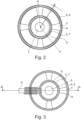
figure 2 est une représentation de face d'un corps d'épreuve instrumenté selon une réalisation de l'invention ; - la
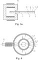
figure 3 représente de face l'aimantation de la piste magnétique intérieure d'un corps d'épreuve selon l'invention, lafigure 3a étant une coupe selon la ligne A-A de lafigure 3 ; - la
figure 4 représente de face l'aimantation de la piste magnétique extérieure d'un corps d'épreuve selon l'invention. - En relation avec ces figures, on décrit ci-dessous un système de détermination d'un couple appliqué entre deux organes tournants autour d'un axe géométrique de rotation R.
- En particulier, le système permet la détermination d'un couple appliqué entre deux organes intégrés dans une transmission d'un couple moteur à un véhicule, par exemple entre le moteur électrique et la transmission mécanique d'un vélo à assistance électrique.
- Le système comprend un corps d'épreuve présentant une bague intérieure 1 solidaire en rotation de moyens de montage dudit corps d'épreuve sur un organe, et une bague extérieure 2 s'étendant autour de la bague intérieure 1 en présentant des moyens de montage dudit corps d'épreuve sur l'autre organe.
- Les bagues 1, 2 sont reliées par une structure déformable qui est agencée pour transmettre le couple entre les organes tout en autorisant un débattement angulaire entre lesdites bagues en fonction du couple appliqué entre lesdits organes.
- Dans le mode de réalisation représenté, les bagues 1, 2 sont concentriques autour d'un manchon de montage 3 sur l'axe géométrique de rotation R, par exemple un arbre de transmission du couple à un autre arbre sur lequel la bague extérieure 2 est montée, la structure déformable comprenant au moins un bras radial 4 - quatre équirépartis angulairement sur les figures - qui relie les bagues 1, 2.
- Ainsi, le couple transmis entre les arbres induit une torsion des bagues 1, 2 et donc un déplacement angulaire relatif desdites bagues suivant un angle de torsion qui est fonction dudit couple, le système déterminant ledit couple sur la base de la mesure dudit angle de torsion.
- Pour ce faire, un codeur est réalisé avec le corps d'épreuve en équipant chacune des bagues 1, 2 avec un anneau respectivement intérieur 5 et extérieur 6 portant une piste magnétique respectivement intérieure 7 et extérieure 8 qui est apte à émettre un signal, par exemple périodique, représentatif du déplacement dudit anneau en rotation, le système comprenant un capteur de mesure de la position angulaire de chacun desdits anneaux.
- En particulier, une succession de respectivement Nppi et Nppe paires de pôles 9 Nord et Sud est aimantée sur un anneau 5, 6 pour former une piste magnétique multipolaire 7, 8 apte à émettre un signal magnétique de forme pseudo-sinusoïdale.
- Les anneaux 5, 6 peuvent comprendre une matrice annulaire, par exemple réalisée à base d'un matériau plastique ou élastomère, dans laquelle sont dispersées des particules magnétiques, notamment des particules de ferrite ou de terres rares comme le NdFeB, lesdites particules étant aimantées pour former les pistes magnétiques 7, 8.
- Le capteur comprend un premier - respectivement un deuxième - motif d'éléments sensibles disposé à distance de lecture de la piste intérieure 7 - respectivement de la piste extérieure 8 - pour former un signal représentatif de la position angulaire de l'anneau 5, 6 correspondant.
- En particulier, chaque motif peut comprendre au moins deux éléments sensibles, notamment une pluralité d'éléments sensibles alignés tel que décrit dans les documents
FR-2 792 403 EP-2 602 593 etEP-2 602 594 . - Les éléments sensibles peuvent être à base d'un matériau magnétorésistif dont la résistance varie en fonction du signal magnétique de la piste 7, 8 à détecter, par exemple de type AMR, TMR ou GMR, ou d'une sonde à effet Hall.
- Selon une réalisation, la position angulaire peut être déterminée de façon incrémentale au moyen du signal émis par une piste magnétique 7, 8. Selon une autre réalisation, la position angulaire peut être déterminée de façon absolue, c'est-à-dire par rapport à une position de référence, en prévoyant une piste magnétique secondaire ou un codage spécifique sur l'anneau 5, 6.
- Le système comprend en outre un dispositif de comparaison des signaux délivrés par le capteur, ledit dispositif étant apte à déterminer un angle entre les bagues 1, 2 qui est fonction du couple appliqué.
- Selon une réalisation, les capteurs délivrent des signaux carrés incrémentaux en quadrature, le dispositif de comparaison comprenant des moyens de comptage indiquant la position angulaire de chacun des anneaux 5, 6 et des moyens de soustraction permettant de calculer la différence entre lesdites positions angulaires.
- Le capteur peut comprendre des moyens d'application d'un facteur d'interpolation fi et fe au signal délivré par respectivement le premier et le deuxième motif d'éléments sensibles, les moyens de comptage mesurant un nombre de fronts ni et ne dans chacun desdits signaux interpolés.
- En relation avec des pistes intérieure 7 et extérieure 8 comprenant respectivement Nppi et Nppe paires de pôles 9 Nord et Sud, les moyens de soustraction effectuent par exemple l'opération Nppe.fe.ni - Nppi.fi.ne pour calculer la différence entre les positions angulaires des anneaux 5, 6.
- En particulier, le capteur comprend des moyens d'application de facteurs d'interpolation tels que : fe/fi = Nppi/Nppe. Lorsque les pistes 7, 8 présentent le même nombre de paires de pôles 9 (Nppi = Nppe) et donc une largeur polaire différente d'une piste 7 par rapport à l'autre piste 8, le calcul peut être réalisé par simple soustraction des fronts ni et ne avec un même facteur d'interpolation (fi = fe).
- Selon une réalisation, les nombres Nppi et Nppe de paires de pôles 9 sont tels que les pôles 9 des pistes 7, 8 présentent une largeur polaire qui est identique, ce qui procure l'avantage de pouvoir utiliser des motifs d'éléments sensibles avec la même configuration et dans les mêmes conditions de fonctionnement. On peut ainsi compenser leurs erreurs relatives à une période magnétique, par exemple leur non-linéarité ou d'autres défauts intrinsèques communs.
- Le procédé de réalisation du codeur prévoit de fixer d'abord les anneaux 5, 6 sur le corps, puis d'aimanter chacune des pistes magnétiques 7, 8 de façon concentrique pour qu'elles présentent un axe de révolution commun P.
- Dans le mode de réalisation représenté, les anneaux 5, 6 sont fixés avant leur aimantation sur respectivement une bague 1, 2 du corps pour former respectivement la piste magnétique intérieure 7 et la piste magnétique extérieure 8 par aimantation ultérieure.
- De façon avantageuse, le procédé prévoit de fixer de façon concentrique les anneaux 5, 6 sur les bagues 1, 2 pour qu'ils présentent un axe de révolution commun avec l'axe géométrique de rotation R.
- La fixation préalable permet que les anneaux 5, 6 présentent la même excentration mécanique qui est induite par une éventuelle distance entre leur centre et l'axe géométrique de rotation R, et l'aimantation ultérieure des pistes permet d'obtenir une même excentration magnétique e entre leur axe de révolution commun P et l'axe géométrique de rotation R.
- Ainsi, les excentrations e étant les mêmes, leurs éventuels défauts n'affectent pas la précision de la détermination d'un couple par comparaison de la position angulaire de chacun des anneaux 5, 6, dans la mesure où l'erreur de position sera alors la même et pourra donc être éliminée par soustraction.
- Selon un mode de réalisation, les pistes 7, 8 sont aimantées au moyen d'un outil 10 qui présente deux couronnes d'aimantation de respectivement un anneau 5, 6 fixé sur le corps, les couronnes pouvant présenter avantageusement une géométrie analogue à la géométrie de respectivement un anneau 5, 6.
- Cette réalisation permet de pouvoir aimanter les pistes 7, 8 simultanément en respectant de façon simple leur concentricité dans la mesure où elle est imposée par la géométrie des couronnes d'aimantation.
- L'aimantation peut est réalisée au moyen d'un outil 10 de sorte notamment à pouvoir aimanter les anneaux 5, 6 fixés sur les bagues 1, 2 avec leurs pistes magnétiques 7, 8 disposées dans un plan L, lesdites pistes pouvant comporter un nombre de paires de pôles 9 identique ou différent.
- Selon une autre réalisation, les pistes 7, 8 sont aimantées au moyen d'un outil 11, le corps et ledit outil étant montés en rotation relative selon l'axe de révolution commun P. En particulier, l'outil 11 peut être fixe et le corps monté en rotation par rapport audit outil.
- En relation avec les
figures 3 et4 , le procédé prévoit un outil 11 d'aimantation d'un pôle 9, d'une paire de pôles 9 adjacents ou d'une succession angulaire de pôles 9, ledit outil et respectivement un anneau 5, 6 étant déplacés relativement pour être radialement en regard pour aimanter successivement les pôles 9 d'une piste 7, 8 par rotations successives relatives dudit outil par rapport audit anneau.
Claims (15)
- Corps d'épreuve pour un système de détermination d'un couple appliqué entre deux organes tournants autour d'un axe géométrique de rotation (R), ledit corps d'épreuve présentant une bague intérieure (1) solidaire en rotation de moyens de montage dudit corps d'épreuve sur un organe, et une bague extérieure (2) s'étendant autour de la bague intérieure (1) en présentant des moyens de montage dudit corps d'épreuve sur l'autre organe, lesdites bagues étant reliées par une structure déformable qui est agencée pour transmettre le couple entre les organes tout en autorisant un débattement angulaire entre lesdites bagues en fonction du couple appliqué entre lesdits organes, ledit corps d'épreuve étant caractérisé en ce qu'il est équipé de deux anneaux (5, 6) portant chacun une piste magnétique (7, 8) qui est apte à émettre un signal représentatif du déplacement dudit anneau en rotation, les anneaux (5, 6) étant fixés sur respectivement une bague (1, 2) et les pistes magnétiques (7, 8) étant aimantées de façon concentrique pour qu'elles présentent un axe de révolution commun (P) de sorte à former respectivement une piste magnétique intérieure (7) et une piste magnétique extérieure (8) d'un codeur.
- Corps d'épreuve selon la revendication 1, caractérisé en ce que les anneaux (5, 6) présentent un axe de révolution commun avec l'axe géométrique de rotation (R).
- Corps d'épreuve selon l'une des revendications 1 ou 2, caractérisé en ce que les anneaux (5, 6) sont fixés sur le corps de sorte que leurs pistes (7, 8) soient disposées dans un plan (L).
- Corps d'épreuve selon l'une quelconque des revendications 1 à 3, caractérisé en ce que les deux anneaux (5, 6) comprennent une matrice annulaire dans laquelle sont dispersées des particules magnétiques, lesdites particules étant aimantées pour former les pistes magnétiques (7, 8).
- Corps d'épreuve selon l'une quelconque des revendications 1 à 4, caractérisé en ce que la structure déformable comprend au moins un bras radial (4) qui relie les bagues (1, 2).
- Corps d'épreuve selon l'une quelconque des revendications 1 à 5, caractérisé en ce que les pistes intérieure (7) et extérieure (8) comprennent respectivement Nppi et Nppe paires de pôles (9) Nord et Sud pour former les pistes magnétiques multipolaires (7, 8).
- Corps d'épreuve selon la revendication 6, caractérisé en ce que les nombres Nppi et Nppe de paires de pôles (9) sont tels que les pôles (9) des pistes (7, 8) présentent une largeur polaire qui est identique.
- Procédé de réalisation d'un corps d'épreuve selon l'une quelconque des revendications 1 à 7, ledit procédé prévoyant de :- fixer les anneaux (5, 6) sur respectivement une bague (1, 2) ; puis- aimanter chacune des pistes magnétiques (7, 8) de façon concentrique pour qu'elles présentent un axe de révolution commun (P).
- Procédé de réalisation selon la revendication 8, caractérisé en ce que les pistes (7, 8) sont aimantées simultanément.
- Procédé de réalisation selon la revendication 8, caractérisé en ce que les pistes (7, 8) sont aimantées au moyen d'un outil (11), le corps d'épreuve et ledit outil étant montés en rotation relative selon l'axe de révolution commun (P).
- Procédé de réalisation selon la revendication 10 lorsqu'elle dépend de la revendication 6, caractérisé en ce qu'il prévoit un outil (11) d'aimantation d'un pôle (9), d'une paire de pôles (9) adjacents ou d'une succession angulaire de pôles (9), ledit outil et respectivement un anneau (5, 6) étant déplacés relativement pour être radialement en regard pour aimanter successivement les pôles (9) d'une piste (7, 8) par rotations successives relatives dudit outil par rapport audit anneau.
- Système de détermination d'un couple appliqué entre deux organes tournants autour d'un axe géométrique de rotation (R), ledit système comprenant un corps d'épreuve selon l'une quelconque des revendications 1 à 7 et un capteur comprenant un premier - respectivement un deuxième - motif d'éléments sensibles disposé à distance de lecture de la piste intérieure (7) - respectivement de la piste extérieure (8) - pour former un signal représentatif de la position angulaire de l'anneau (5, 6) correspondant, ledit système comprenant en outre un dispositif de comparaison des signaux délivrés par le capteur, ledit dispositif étant apte à déterminer un angle entre les bagues (1, 2) qui est fonction du couple appliqué.
- Système de détermination selon la revendication 12, caractérisé en ce que les capteurs délivrent des signaux carrés incrémentaux en quadrature, le dispositif de comparaison comprenant des moyens de comptage indiquant la position angulaire de chacun des anneaux (5, 6) et des moyens de soustraction permettant de calculer la différence entre lesdites positions angulaires.
- Système de détermination selon la revendication 13 lorsqu'elle dépend de la revendication 6, caractérisé en ce que le capteur comprend des moyens d'application d'un facteur d'interpolation fi et fe au signal délivré par respectivement le premier et le deuxième motif d'éléments sensibles, les moyens de comptage mesurant un nombre de fronts ni et ne dans chacun desdits signaux interpolés, les moyens de soustraction effectuant l'opération Nppe.fe.ni - Nppi.fi.ne pour calculer la différence entre les positions angulaires des anneaux (5, 6).
- Système de détermination selon la revendication 14, caractérisé en ce que le capteur comprend des moyens d'application de facteurs d'interpolation tels que : fe/fi = Nppi/Nppe.
Applications Claiming Priority (1)
| Application Number | Priority Date | Filing Date | Title |
|---|---|---|---|
| FR2201675A FR3133080B1 (fr) | 2022-02-25 | 2022-02-25 | Procédé de réalisation d’un codeur |
Publications (2)
| Publication Number | Publication Date |
|---|---|
| EP4235109A1 EP4235109A1 (fr) | 2023-08-30 |
| EP4235109B1 true EP4235109B1 (fr) | 2024-12-25 |
Family
ID=82319896
Family Applications (1)
| Application Number | Title | Priority Date | Filing Date |
|---|---|---|---|
| EP23157459.1A Active EP4235109B1 (fr) | 2022-02-25 | 2023-02-20 | Corps d'épreuve équipé d'un codeur |
Country Status (6)
| Country | Link |
|---|---|
| US (1) | US20230273079A1 (fr) |
| EP (1) | EP4235109B1 (fr) |
| JP (1) | JP2023124862A (fr) |
| CN (1) | CN116659716A (fr) |
| FR (1) | FR3133080B1 (fr) |
| TW (1) | TW202344817A (fr) |
Family Cites Families (16)
| Publication number | Priority date | Publication date | Assignee | Title |
|---|---|---|---|---|
| FR2774469B1 (fr) * | 1998-02-04 | 2000-03-03 | Roulements Soc Nouvelle | Capteur de couple pour arbre tournant |
| FR2792403B1 (fr) | 1999-04-14 | 2001-05-25 | Roulements Soc Nouvelle | Capteur de position et/ou de deplacement comportant une pluralite d'elements sensibles alignes |
| FR2821931B1 (fr) | 2001-03-09 | 2003-05-09 | Roulements Soc Nouvelle | Dispositif de mesure analogique d'un couple de torsion, colonne de direction et module le comprenant |
| US6948384B2 (en) * | 2002-09-10 | 2005-09-27 | Siemens Vdo Automotive Corporation | Coupler for torque sensor |
| FR2862382B1 (fr) * | 2003-11-18 | 2006-06-02 | Roulements Soc Nouvelle | Systeme capteur de couple absolu de torsion et module le comprenant |
| US8085036B2 (en) * | 2009-01-14 | 2011-12-27 | Infineon Technologies Ag | Sensor including two code rings and a magnetic field sensor between the code rings |
| EP2602593B1 (fr) | 2011-12-05 | 2017-07-05 | Sensitec GmbH | Capteur pour mesurer un signal périodique comprenant plusieurs harmoniques |
| EP2602594B1 (fr) | 2011-12-05 | 2018-02-07 | NTN-SNR Roulements | Capteur pour mesurer un signal périodique comprenant plusieurs harmoniques |
| JP5973278B2 (ja) * | 2012-08-16 | 2016-08-23 | Ntn株式会社 | 磁気エンコーダの着磁装置 |
| US8984963B2 (en) * | 2013-03-15 | 2015-03-24 | H. Aaron Christmann | Rotatable torque-measuring apparatus and method |
| US9976874B2 (en) * | 2013-07-16 | 2018-05-22 | Ntn Corporation | Magnetic encoder device and rotation detection device |
| EP3290886B1 (fr) * | 2015-06-26 | 2020-11-25 | NSK Ltd. | Appareil de détection d'angle relatif, capteur de couple, appareil de direction à assistance électrique, et véhicule |
| JP2017223528A (ja) * | 2016-06-15 | 2017-12-21 | Ntn株式会社 | トルク検出装置 |
| JP6830423B2 (ja) * | 2017-09-22 | 2021-02-17 | Ntn株式会社 | トルク検出装置 |
| FR3078775B1 (fr) * | 2018-03-12 | 2020-04-03 | Ntn-Snr Roulements | Systeme de determination d'au moins un parametre de rotation d'un organe tournant |
| IT202100006692A1 (it) * | 2021-03-19 | 2022-09-19 | Lika Electronic S R L | Apparecchiatura di trasduzione di posizione/spostamenti e sistema e metodo correlati |
-
2022
- 2022-02-25 FR FR2201675A patent/FR3133080B1/fr active Active
-
2023
- 2023-02-20 EP EP23157459.1A patent/EP4235109B1/fr active Active
- 2023-02-21 US US18/112,488 patent/US20230273079A1/en active Pending
- 2023-02-24 CN CN202310166173.XA patent/CN116659716A/zh active Pending
- 2023-02-24 TW TW112107113A patent/TW202344817A/zh unknown
- 2023-02-27 JP JP2023028341A patent/JP2023124862A/ja active Pending
Also Published As
| Publication number | Publication date |
|---|---|
| CN116659716A (zh) | 2023-08-29 |
| FR3133080B1 (fr) | 2024-05-31 |
| EP4235109A1 (fr) | 2023-08-30 |
| FR3133080A1 (fr) | 2023-09-01 |
| TW202344817A (zh) | 2023-11-16 |
| US20230273079A1 (en) | 2023-08-31 |
| JP2023124862A (ja) | 2023-09-06 |
Similar Documents
| Publication | Publication Date | Title |
|---|---|---|
| EP1403622B1 (fr) | Capteur d'angle absolu | |
| WO2009047401A2 (fr) | Capteur magnétique sans contact de position absolue multitour à arbre traversant | |
| FR2947902A1 (fr) | Capteur de position absolue et multi-periodique | |
| EP1533600A1 (fr) | Système capteur de couple absolu de torsion et module le comprenant | |
| EP2163850B1 (fr) | Dispositif de codage magnétique | |
| EP1403621B1 (fr) | Capteur d'angle absolu | |
| EP4235127B1 (fr) | Système de détermination d'un couple | |
| EP4235109A1 (fr) | Corps d'épreuve équipé d'un codeur | |
| FR2950426A1 (fr) | Capteur de position angulaire sans contact | |
| EP4343296A1 (fr) | Procédé de détermination d'un couple appliqué entre deux organes tournant | |
| EP1875184A2 (fr) | Dispositif et procede de mesure de couple de torsion | |
| EP3708963B1 (fr) | Système de détermination d'au moins un paramètre de rotation d'un organe tournant | |
| EP4278154B1 (fr) | Capteur de position sans contact comportant un aimant permanent | |
| EP4303553A1 (fr) | Système de détermination d'un couple appliqué entre deux organes tournants | |
| EP2213990B1 (fr) | Procédé de calibration et/ou de correction d'un dispositif d'affichage ayant une aiguille, l'aiguille étant mobile en rotation autour d'un axe de rotation | |
| FR3143733A1 (fr) | Système de détermination d’au moins un paramètre de rotation d’un organe tournant | |
| EP4610611A1 (fr) | Système de détermination d'une information de rotation d'un organe | |
| WO2024194486A1 (fr) | Procédé de détermination d'un couple appliqué entre deux organes tournants | |
| EP0989050A1 (fr) | Système à capteur d'angle, notamment pour colonne de direction de véhicule automobile | |
| FR3160466A1 (fr) | Système de détermination d’un couple appliqué entre deux organes tournants | |
| FR2829574A1 (fr) | Capteur de la position d'un objet mobile, sur une trajectoire rectiligne | |
| EP3708964A1 (fr) | Système de détermination d'au moins un paramètre de rotation d'un organe tournant | |
| FR3149087A1 (fr) | Système de détermination d’un couple appliqué entre deux organes tournants | |
| FR3142252A1 (fr) | Système de détermination d’un couple appliqué entre deux organes | |
| WO2023217918A1 (fr) | Tachymetre pour roue d'aeronef |
Legal Events
| Date | Code | Title | Description |
|---|---|---|---|
| PUAI | Public reference made under article 153(3) epc to a published international application that has entered the european phase |
Free format text: ORIGINAL CODE: 0009012 |
|
| STAA | Information on the status of an ep patent application or granted ep patent |
Free format text: STATUS: THE APPLICATION HAS BEEN PUBLISHED |
|
| AK | Designated contracting states |
Kind code of ref document: A1 Designated state(s): AL AT BE BG CH CY CZ DE DK EE ES FI FR GB GR HR HU IE IS IT LI LT LU LV MC ME MK MT NL NO PL PT RO RS SE SI SK SM TR |
|
| RAP3 | Party data changed (applicant data changed or rights of an application transferred) |
Owner name: NTN EUROPE |
|
| STAA | Information on the status of an ep patent application or granted ep patent |
Free format text: STATUS: REQUEST FOR EXAMINATION WAS MADE |
|
| 17P | Request for examination filed |
Effective date: 20240223 |
|
| RBV | Designated contracting states (corrected) |
Designated state(s): AL AT BE BG CH CY CZ DE DK EE ES FI FR GB GR HR HU IE IS IT LI LT LU LV MC ME MK MT NL NO PL PT RO RS SE SI SK SM TR |
|
| GRAP | Despatch of communication of intention to grant a patent |
Free format text: ORIGINAL CODE: EPIDOSNIGR1 |
|
| STAA | Information on the status of an ep patent application or granted ep patent |
Free format text: STATUS: GRANT OF PATENT IS INTENDED |
|
| INTG | Intention to grant announced |
Effective date: 20240722 |
|
| GRAS | Grant fee paid |
Free format text: ORIGINAL CODE: EPIDOSNIGR3 |
|
| GRAA | (expected) grant |
Free format text: ORIGINAL CODE: 0009210 |
|
| STAA | Information on the status of an ep patent application or granted ep patent |
Free format text: STATUS: THE PATENT HAS BEEN GRANTED |
|
| AK | Designated contracting states |
Kind code of ref document: B1 Designated state(s): AL AT BE BG CH CY CZ DE DK EE ES FI FR GB GR HR HU IE IS IT LI LT LU LV MC ME MK MT NL NO PL PT RO RS SE SI SK SM TR |
|
| REG | Reference to a national code |
Ref country code: GB Ref legal event code: FG4D Free format text: NOT ENGLISH |
|
| REG | Reference to a national code |
Ref country code: CH Ref legal event code: EP |
|
| REG | Reference to a national code |
Ref country code: DE Ref legal event code: R096 Ref document number: 602023001439 Country of ref document: DE |
|
| REG | Reference to a national code |
Ref country code: IE Ref legal event code: FG4D Free format text: LANGUAGE OF EP DOCUMENT: FRENCH |
|
| REG | Reference to a national code |
Ref country code: LT Ref legal event code: MG9D |
|
| PG25 | Lapsed in a contracting state [announced via postgrant information from national office to epo] |
Ref country code: HR Free format text: LAPSE BECAUSE OF FAILURE TO SUBMIT A TRANSLATION OF THE DESCRIPTION OR TO PAY THE FEE WITHIN THE PRESCRIBED TIME-LIMIT Effective date: 20241225 |
|
| PG25 | Lapsed in a contracting state [announced via postgrant information from national office to epo] |
Ref country code: FI Free format text: LAPSE BECAUSE OF FAILURE TO SUBMIT A TRANSLATION OF THE DESCRIPTION OR TO PAY THE FEE WITHIN THE PRESCRIBED TIME-LIMIT Effective date: 20241225 |
|
| PG25 | Lapsed in a contracting state [announced via postgrant information from national office to epo] |
Ref country code: BG Free format text: LAPSE BECAUSE OF FAILURE TO SUBMIT A TRANSLATION OF THE DESCRIPTION OR TO PAY THE FEE WITHIN THE PRESCRIBED TIME-LIMIT Effective date: 20241225 |
|
| PG25 | Lapsed in a contracting state [announced via postgrant information from national office to epo] |
Ref country code: NO Free format text: LAPSE BECAUSE OF FAILURE TO SUBMIT A TRANSLATION OF THE DESCRIPTION OR TO PAY THE FEE WITHIN THE PRESCRIBED TIME-LIMIT Effective date: 20250325 |
|
| PG25 | Lapsed in a contracting state [announced via postgrant information from national office to epo] |
Ref country code: LV Free format text: LAPSE BECAUSE OF FAILURE TO SUBMIT A TRANSLATION OF THE DESCRIPTION OR TO PAY THE FEE WITHIN THE PRESCRIBED TIME-LIMIT Effective date: 20241225 Ref country code: GR Free format text: LAPSE BECAUSE OF FAILURE TO SUBMIT A TRANSLATION OF THE DESCRIPTION OR TO PAY THE FEE WITHIN THE PRESCRIBED TIME-LIMIT Effective date: 20250326 |
|
| PGFP | Annual fee paid to national office [announced via postgrant information from national office to epo] |
Ref country code: AT Payment date: 20250417 Year of fee payment: 3 |
|
| PG25 | Lapsed in a contracting state [announced via postgrant information from national office to epo] |
Ref country code: RS Free format text: LAPSE BECAUSE OF FAILURE TO SUBMIT A TRANSLATION OF THE DESCRIPTION OR TO PAY THE FEE WITHIN THE PRESCRIBED TIME-LIMIT Effective date: 20250325 |
|
| REG | Reference to a national code |
Ref country code: NL Ref legal event code: MP Effective date: 20241225 |
|
| PG25 | Lapsed in a contracting state [announced via postgrant information from national office to epo] |
Ref country code: NL Free format text: LAPSE BECAUSE OF FAILURE TO SUBMIT A TRANSLATION OF THE DESCRIPTION OR TO PAY THE FEE WITHIN THE PRESCRIBED TIME-LIMIT Effective date: 20241225 |
|
| REG | Reference to a national code |
Ref country code: AT Ref legal event code: MK05 Ref document number: 1754501 Country of ref document: AT Kind code of ref document: T Effective date: 20241225 |
|
| PG25 | Lapsed in a contracting state [announced via postgrant information from national office to epo] |
Ref country code: SM Free format text: LAPSE BECAUSE OF FAILURE TO SUBMIT A TRANSLATION OF THE DESCRIPTION OR TO PAY THE FEE WITHIN THE PRESCRIBED TIME-LIMIT Effective date: 20241225 |
|
| PG25 | Lapsed in a contracting state [announced via postgrant information from national office to epo] |
Ref country code: PL Free format text: LAPSE BECAUSE OF FAILURE TO SUBMIT A TRANSLATION OF THE DESCRIPTION OR TO PAY THE FEE WITHIN THE PRESCRIBED TIME-LIMIT Effective date: 20241225 |
|
| PG25 | Lapsed in a contracting state [announced via postgrant information from national office to epo] |
Ref country code: ES Free format text: LAPSE BECAUSE OF FAILURE TO SUBMIT A TRANSLATION OF THE DESCRIPTION OR TO PAY THE FEE WITHIN THE PRESCRIBED TIME-LIMIT Effective date: 20241225 |
|
| PG25 | Lapsed in a contracting state [announced via postgrant information from national office to epo] |
Ref country code: IS Free format text: LAPSE BECAUSE OF FAILURE TO SUBMIT A TRANSLATION OF THE DESCRIPTION OR TO PAY THE FEE WITHIN THE PRESCRIBED TIME-LIMIT Effective date: 20250425 |
|
| PG25 | Lapsed in a contracting state [announced via postgrant information from national office to epo] |
Ref country code: PT Free format text: LAPSE BECAUSE OF FAILURE TO SUBMIT A TRANSLATION OF THE DESCRIPTION OR TO PAY THE FEE WITHIN THE PRESCRIBED TIME-LIMIT Effective date: 20250428 |
|
| PG25 | Lapsed in a contracting state [announced via postgrant information from national office to epo] |
Ref country code: EE Free format text: LAPSE BECAUSE OF FAILURE TO SUBMIT A TRANSLATION OF THE DESCRIPTION OR TO PAY THE FEE WITHIN THE PRESCRIBED TIME-LIMIT Effective date: 20241225 |
|
| PG25 | Lapsed in a contracting state [announced via postgrant information from national office to epo] |
Ref country code: RO Free format text: LAPSE BECAUSE OF FAILURE TO SUBMIT A TRANSLATION OF THE DESCRIPTION OR TO PAY THE FEE WITHIN THE PRESCRIBED TIME-LIMIT Effective date: 20241225 Ref country code: AT Free format text: LAPSE BECAUSE OF FAILURE TO SUBMIT A TRANSLATION OF THE DESCRIPTION OR TO PAY THE FEE WITHIN THE PRESCRIBED TIME-LIMIT Effective date: 20241225 |
|
| PG25 | Lapsed in a contracting state [announced via postgrant information from national office to epo] |
Ref country code: SK Free format text: LAPSE BECAUSE OF FAILURE TO SUBMIT A TRANSLATION OF THE DESCRIPTION OR TO PAY THE FEE WITHIN THE PRESCRIBED TIME-LIMIT Effective date: 20241225 |
|
| PG25 | Lapsed in a contracting state [announced via postgrant information from national office to epo] |
Ref country code: CZ Free format text: LAPSE BECAUSE OF FAILURE TO SUBMIT A TRANSLATION OF THE DESCRIPTION OR TO PAY THE FEE WITHIN THE PRESCRIBED TIME-LIMIT Effective date: 20241225 |
|
| PG25 | Lapsed in a contracting state [announced via postgrant information from national office to epo] |
Ref country code: IT Free format text: LAPSE BECAUSE OF FAILURE TO SUBMIT A TRANSLATION OF THE DESCRIPTION OR TO PAY THE FEE WITHIN THE PRESCRIBED TIME-LIMIT Effective date: 20241225 |
|
| PG25 | Lapsed in a contracting state [announced via postgrant information from national office to epo] |
Ref country code: SE Free format text: LAPSE BECAUSE OF FAILURE TO SUBMIT A TRANSLATION OF THE DESCRIPTION OR TO PAY THE FEE WITHIN THE PRESCRIBED TIME-LIMIT Effective date: 20241225 |
|
| PG25 | Lapsed in a contracting state [announced via postgrant information from national office to epo] |
Ref country code: MC Free format text: LAPSE BECAUSE OF FAILURE TO SUBMIT A TRANSLATION OF THE DESCRIPTION OR TO PAY THE FEE WITHIN THE PRESCRIBED TIME-LIMIT Effective date: 20241225 |
|
| REG | Reference to a national code |
Ref country code: DE Ref legal event code: R097 Ref document number: 602023001439 Country of ref document: DE |
|
| PG25 | Lapsed in a contracting state [announced via postgrant information from national office to epo] |
Ref country code: DK Free format text: LAPSE BECAUSE OF FAILURE TO SUBMIT A TRANSLATION OF THE DESCRIPTION OR TO PAY THE FEE WITHIN THE PRESCRIBED TIME-LIMIT Effective date: 20241225 |
|
| PG25 | Lapsed in a contracting state [announced via postgrant information from national office to epo] |
Ref country code: LU Free format text: LAPSE BECAUSE OF NON-PAYMENT OF DUE FEES Effective date: 20250220 |
|
| PLBE | No opposition filed within time limit |
Free format text: ORIGINAL CODE: 0009261 |
|
| STAA | Information on the status of an ep patent application or granted ep patent |
Free format text: STATUS: NO OPPOSITION FILED WITHIN TIME LIMIT |
|
| 26N | No opposition filed |
Effective date: 20250926 |
|
| REG | Reference to a national code |
Ref country code: BE Ref legal event code: MM Effective date: 20250228 |
|
| PG25 | Lapsed in a contracting state [announced via postgrant information from national office to epo] |
Ref country code: BE Free format text: LAPSE BECAUSE OF NON-PAYMENT OF DUE FEES Effective date: 20250228 |
|
| PG25 | Lapsed in a contracting state [announced via postgrant information from national office to epo] |
Ref country code: IE Free format text: LAPSE BECAUSE OF NON-PAYMENT OF DUE FEES Effective date: 20250220 |
|
| PGFP | Annual fee paid to national office [announced via postgrant information from national office to epo] |
Ref country code: DE Payment date: 20260218 Year of fee payment: 4 |
|
| PGFP | Annual fee paid to national office [announced via postgrant information from national office to epo] |
Ref country code: FR Payment date: 20260219 Year of fee payment: 4 |