EP4235085B1 - Téléopération sécurisée d'un système d'arme - Google Patents
Téléopération sécurisée d'un système d'arme Download PDFInfo
- Publication number
- EP4235085B1 EP4235085B1 EP22158756.1A EP22158756A EP4235085B1 EP 4235085 B1 EP4235085 B1 EP 4235085B1 EP 22158756 A EP22158756 A EP 22158756A EP 4235085 B1 EP4235085 B1 EP 4235085B1
- Authority
- EP
- European Patent Office
- Prior art keywords
- bus
- client
- transceiver
- radio
- weapons
- Prior art date
- Legal status (The legal status is an assumption and is not a legal conclusion. Google has not performed a legal analysis and makes no representation as to the accuracy of the status listed.)
- Active
Links
Images


Classifications
-
- F—MECHANICAL ENGINEERING; LIGHTING; HEATING; WEAPONS; BLASTING
- F41—WEAPONS
- F41G—WEAPON SIGHTS; AIMING
- F41G5/00—Elevating or traversing control systems for guns
- F41G5/06—Elevating or traversing control systems for guns using electric means for remote control
-
- F—MECHANICAL ENGINEERING; LIGHTING; HEATING; WEAPONS; BLASTING
- F41—WEAPONS
- F41G—WEAPON SIGHTS; AIMING
- F41G3/00—Aiming or laying means
- F41G3/14—Indirect aiming means
- F41G3/16—Sighting devices adapted for indirect laying of fire
- F41G3/165—Sighting devices adapted for indirect laying of fire using a TV-monitor
-
- F—MECHANICAL ENGINEERING; LIGHTING; HEATING; WEAPONS; BLASTING
- F41—WEAPONS
- F41G—WEAPON SIGHTS; AIMING
- F41G5/00—Elevating or traversing control systems for guns
- F41G5/14—Elevating or traversing control systems for guns for vehicle-borne guns
-
- F—MECHANICAL ENGINEERING; LIGHTING; HEATING; WEAPONS; BLASTING
- F41—WEAPONS
- F41G—WEAPON SIGHTS; AIMING
- F41G5/00—Elevating or traversing control systems for guns
- F41G5/14—Elevating or traversing control systems for guns for vehicle-borne guns
- F41G5/24—Elevating or traversing control systems for guns for vehicle-borne guns for guns on tanks
-
- H—ELECTRICITY
- H04—ELECTRIC COMMUNICATION TECHNIQUE
- H04L—TRANSMISSION OF DIGITAL INFORMATION, e.g. TELEGRAPHIC COMMUNICATION
- H04L12/00—Data switching networks
- H04L12/28—Data switching networks characterised by path configuration, e.g. LAN [Local Area Networks] or WAN [Wide Area Networks]
- H04L12/40—Bus networks
-
- H—ELECTRICITY
- H04—ELECTRIC COMMUNICATION TECHNIQUE
- H04L—TRANSMISSION OF DIGITAL INFORMATION, e.g. TELEGRAPHIC COMMUNICATION
- H04L12/00—Data switching networks
- H04L12/28—Data switching networks characterised by path configuration, e.g. LAN [Local Area Networks] or WAN [Wide Area Networks]
- H04L12/46—Interconnection of networks
-
- H—ELECTRICITY
- H04—ELECTRIC COMMUNICATION TECHNIQUE
- H04L—TRANSMISSION OF DIGITAL INFORMATION, e.g. TELEGRAPHIC COMMUNICATION
- H04L12/00—Data switching networks
- H04L12/28—Data switching networks characterised by path configuration, e.g. LAN [Local Area Networks] or WAN [Wide Area Networks]
- H04L12/40—Bus networks
- H04L2012/40208—Bus networks characterized by the use of a particular bus standard
- H04L2012/40215—Controller Area Network CAN
-
- H—ELECTRICITY
- H04—ELECTRIC COMMUNICATION TECHNIQUE
- H04L—TRANSMISSION OF DIGITAL INFORMATION, e.g. TELEGRAPHIC COMMUNICATION
- H04L12/00—Data switching networks
- H04L12/28—Data switching networks characterised by path configuration, e.g. LAN [Local Area Networks] or WAN [Wide Area Networks]
- H04L12/40—Bus networks
- H04L2012/40267—Bus for use in transportation systems
- H04L2012/40273—Bus for use in transportation systems the transportation system being a vehicle
Definitions
- the present invention falls within the technological field of secure telecommunications which make it possible to control the functions of one or more weapon systems, such as for example unmanned tank turrets, the electronic architecture of which includes a data bus, for example a CAN, Ethernet or other bus.
- weapon systems such as for example unmanned tank turrets
- the present invention is positioned within the framework of the addition of a wireless communications system for the transmission of videos and turret commands and measurements.
- Quality of service refers to any technology capable of managing data transmission, while reducing packet loss, latency and jitter on the network. This concept aims to control and manage network resources, by prioritizing certain types of network data.
- the context involves the remote operation of weapon systems in complex and noisy environments, requiring ad hoc use of bandwidth and frequency depending on the reality on the ground, and this in such a way as to guarantee the quality of service, i.e. taking into account in particular the latency time, and in the most secure way possible, via an appropriate connection mechanism between a control station and one or more weapon systems.
- a field bus (as opposed to a bus for office computer communication) such as the CAN bus or MiICAN, a system based on Ethernet or other.
- a field bus establishes the connection between the sensors, the actuators and the control computer (or PLC, programmable logic controller).
- PLC programmable logic controller
- the document EP 0 419 897 A2 discloses a remote control system for a combat vehicle comprising a remote control apparatus for providing signals to the vehicle to control a plurality of vehicle functions conventionally controlled by personnel on board the vehicle; a vehicle-mounted apparatus selectively operable to receive the signals from the remote control apparatus and to operate the plurality of vehicle functions in accordance with the signals; and an apparatus for selectively disabling the vehicle-mounted apparatus to permit non-remote control of the vehicle functions.
- a digital remote firing system for selectively firing a plurality of remote mission payloads.
- the digital remote firing system includes a first set of firing circuits communicatively coupled and operable to fire a corresponding first set of remote mission payloads and a second set of firing circuits communicatively coupled and operable to fire a corresponding second set of remote mission payloads.
- the digital remote firing system includes a firing control panel communicatively connected to the firing circuits of the first and second sets, a first digital code socket configured to be integrated in communicative combination with each firing circuit of the first set and the firing control panel, a second digital code socket configured to be integrated in communicative combination with each firing circuit of the second set and the firing control panel, and a payload selection switch for selecting a remote mission payload.
- the document EP 1 1947 413 B2 discloses a method for remotely controlling a combat vehicle weapon system with a weapon system computer, which acts on aiming devices of the system weapon system, in which a weapon system display unit for displaying screen contents and a weapon system input unit are connected, which are arranged inside the combat vehicle for controlling the weapon system in a non-remotely controlled mode, whereby a data connection is established between a remote control computer, to which a remote control display unit and a remote control input unit are connected, and the weapon system computer, characterized in that, in a remote control mode for remotely controlling the weapon system computer by the remote control computer, the screen contents displayed in the non-remotely controlled mode on the weapon system display unit are at least partially displayed on the remote control display unit and in that input actions, which are executed by the remote control input unit, act as input actions of the weapon system input unit and in such a way that the weapon system is switchable by the remote control computer remote control in a safe state, in which movement of the weapon system is prevented.
- the document WO 01/65197 A1 discloses a modular system essentially comprising a mobile command post, ground bases and remotely operated weapons.
- the ground bases are distributed over an area to be protected and are responsible for detecting, locating and monitoring intrusions into said area.
- the remotely operated weapons are positioned within firing range of this area and operate either automatically based on data collected by the ground bases or by human intervention from the command post.
- the problem to be solved is to give an existing and operational turret the possibility of being operated indifferently either by on-board personnel or, in particular or dangerous situations, by remote manipulation.
- the main challenge is to reduce the exposure of soldiers in theaters of operation by allowing them to remotely control armored vehicle turrets smoothly, securely and reliably.
- the present invention aims to be able to transform the weapon systems of an existing fleet, and currently operated in a conventional, manned and non-remotely operated mode of use, into a remote-operated mode of use, such as for example the transformation of a turret with on-board personnel (commander and gunner) into an uninhabited turret remotely operated from a remote control station.
- the invention aims to implement via wireless communication, for example radio communication, the security and fluidity of communications between two or more entities not physically connected.
- the invention aims to propose secure and efficient management from the point of view of the concept of quality of service of communications in a hybrid system consisting of two field data buses connected by a radio link, the bus and radio communications having very different constraints.
- Another object of the invention is to enable personnel at the remote control station to have access to the devices, controls, sensors and commands of a weapon system such as a turret exactly as if they were inside the turret.
- a weapon system such as a turret exactly as if they were inside the turret.
- the additional transceiver client must be able to be disconnected from the interface and the turret return to its initial state to be operated by the on-board personnel (commander and gunner typically).
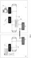
- a weapon system 1 such as an armored vehicle turret, or more generally N weapon systems, uninhabited, is (are) remotely operated from a (same) control station 2 in a simultaneous and dynamic manner (i.e. weapon systems can be added and removed in real time).
- the communications between the control station 2 and the weapon system(s) 1 are wireless communications, preferably radiofrequency communications 3.
- a software defined radio (SDR) system will preferably be used . It is known that this is a configurable radiocommunication system using digital signal processing techniques on programmable digital circuits. Its flexibility allows it to adapt to different radiocommunication protocols, and to meet the growing needs for performance and interoperability between systems.
- SDR software defined radio
- the operator can select which turret 1 he wants to operate, with the radio system setting the radio parameters (frequency, bandwidth, etc.) based on the defined QoS.
- the radio system Preferably, he receives a real-time video signal from cameras embedded in the various selected turrets. He also controls all the functions of the turret he chooses to operate.
- the radio system normally allows video and control data to be transported in full duplex, either in both directions of communication on the radio and the electronic system, via a field bus such as a CAN bus (for Controller Area Network ) , Ethernet or another architecture known to those skilled in the art.
- a field bus such as a CAN bus (for Controller Area Network ) , Ethernet or another architecture known to those skilled in the art.
- the video and data are transmitted on N different channels, N>1 (see FIG. 2 ).
- the number of channels can be configurable by software. Algorithms for searching for free frequencies will be used to avoid jamming and other adverse radio links in order to have optimal operation.
- the control station comprises at least one acquisition interface 4 (screen) and one control interface 5 (keyboard, controller, button, joystick, etc.), on which the operator can operate the selection 6 of a video stream 10 coming from one of the turrets 1. Via the control interface 5, the operator can also control a controller 9 which sends a command 8 to a turret 1, according to the data received from the sensor(s) 7.
- the data transmission channel which is essential for operation, must have as few errors and latency as possible and be full duplex.
- existing means of transmission will be used. and internal to the weapon system, for example the CAN bus, MilCAN or other (see FIG. 3 ).
- All commands from the transmitter and the reception or confirmation messages from the receivers are transmitted and received via the electronic field bus, e.g. CAN, Ethernet or other bus.
- Receivers can be actuators or other elements that can be controlled electrically, by human action or by automation.
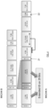
- FIG. 3 shows a schematic view of the control with the data bus and the radio, according to the invention.
- the electronic circuit of the control station 2 comprises a first bus 13 (as described above, for example a CAN bus) to which are connected, in a manner known to those skilled in the art, the controller 9 and a first transceiver (RF modem) 11.
- a first bus 13 as described above, for example a CAN bus
- RF modem first transceiver
- the electronic circuit of the remotely operated turret 1 comprises a second bus 14 (as described above, for example a CAN bus) to which are connected, in a manner known to those skilled in the art, "clients", such as for example a sensor 7 or an actuator 8 as well as an additional client on the weapon system bus which is a second transceiver (RF modem) 12, making it possible to remotely connect the control station 2 to the weapon system 1 in remotely operated mode.
- a second bus 14 as described above, for example a CAN bus
- clients such as for example a sensor 7 or an actuator 8
- RF modem second transceiver
- a transmitter sends for example a frame with a command (or data) to a receiver (client 2)
- client 2 upon receipt of the command by the receiver, the latter will send in return to the transmitter a frame with a message of validation and good reception of the command (called acknowledgment, this notion being well known to those skilled in the art of communication systems).
- a difficulty in controlling communications arises when, for example, there is a loss and/or excessive latency of the radio signal between transmitters and receivers.
- the controller client 1 sends a signal to the electronic system command which is not actually received, so it does not receive the acknowledgment (or acknowledgement) from the receiver (client 2).
- the addition of the "RF modem" client on the CAN bus of the weapon system must not change (almost) in any way the behavior of the CAN bus.
- the RF modem therefore behaves like a conventional client on this bus and will therefore collect the messages to be sent to the control station.
- the reasoning also applies in the other direction (from the control station to the weapon system). This allows a classic and normal operation of the physical CAN bus of the weapon system.
- the RF modem will then send this data to the control station in the most efficient way possible (minimal use of resources so as to guarantee QoS) and request an acknowledgment from the RF modem of the control station. Upon receipt of this acknowledgment by the RF modem of the weapon system, the message is deleted from the memory of this RF modem.
- the RF modem of the weapon system will resend the message to the control station a certain number of times. After this time, determined to ensure latency times for proper remote operation of the weapon system, the weapon system's RF modem enters a degraded mode from a radio point of view and/or tries to transmit the data again. In the event of failure, the RF modem signals to the weapon system's CAN bus that the message has not been transmitted (for example by issuing a "second" acknowledgment). The other CAN bus clients then receive this information and continue their operations based on this information.
- This method can be advantageously applied when there is an overload of sender messages, and/or when there is an arbitration problem when simultaneously sending acknowledgment messages.
- FIG. 4 gives the schematic of the processing of information (frame) by means of a MilCAN bus.
Landscapes
- Engineering & Computer Science (AREA)
- General Engineering & Computer Science (AREA)
- Computer Networks & Wireless Communication (AREA)
- Signal Processing (AREA)
- Selective Calling Equipment (AREA)
- Mobile Radio Communication Systems (AREA)
Priority Applications (10)
| Application Number | Priority Date | Filing Date | Title |
|---|---|---|---|
| PL22158756.1T PL4235085T3 (pl) | 2022-02-25 | 2022-02-25 | Zabezpieczona zdalna obsługa systemu uzbrojenia |
| EP22158756.1A EP4235085B1 (fr) | 2022-02-25 | 2022-02-25 | Téléopération sécurisée d'un système d'arme |
| ES22158756T ES3028672T3 (en) | 2022-02-25 | 2022-02-25 | Secure remote operation unit for a weapon system |
| CA3250633A CA3250633A1 (fr) | 2022-02-25 | 2023-02-17 | Secure remote operation of a weapons system |
| CN202380019252.6A CN118974508A (zh) | 2022-02-25 | 2023-02-17 | 武器系统的安全远程操作 |
| US18/840,531 US12405087B2 (en) | 2022-02-25 | 2023-02-17 | Secure remote operation of a weapons system |
| PCT/EP2023/054067 WO2023161153A1 (fr) | 2022-02-25 | 2023-02-17 | Teleoperation securisee d'un systeme d'arme |
| KR1020247026836A KR20240171064A (ko) | 2022-02-25 | 2023-02-17 | 무기 시스템의 안전한 원격 작동 |
| IL315108A IL315108A (en) | 2022-02-25 | 2023-02-17 | Secure remote operation of a weapons system |
| ZA2024/06239A ZA202406239B (en) | 2022-02-25 | 2024-08-14 | Secure remote operation of a weapons system |
Applications Claiming Priority (1)
| Application Number | Priority Date | Filing Date | Title |
|---|---|---|---|
| EP22158756.1A EP4235085B1 (fr) | 2022-02-25 | 2022-02-25 | Téléopération sécurisée d'un système d'arme |
Publications (3)
| Publication Number | Publication Date |
|---|---|
| EP4235085A1 EP4235085A1 (fr) | 2023-08-30 |
| EP4235085C0 EP4235085C0 (fr) | 2025-04-02 |
| EP4235085B1 true EP4235085B1 (fr) | 2025-04-02 |
Family
ID=80780858
Family Applications (1)
| Application Number | Title | Priority Date | Filing Date |
|---|---|---|---|
| EP22158756.1A Active EP4235085B1 (fr) | 2022-02-25 | 2022-02-25 | Téléopération sécurisée d'un système d'arme |
Country Status (10)
| Country | Link |
|---|---|
| US (1) | US12405087B2 (es) |
| EP (1) | EP4235085B1 (es) |
| KR (1) | KR20240171064A (es) |
| CN (1) | CN118974508A (es) |
| CA (1) | CA3250633A1 (es) |
| ES (1) | ES3028672T3 (es) |
| IL (1) | IL315108A (es) |
| PL (1) | PL4235085T3 (es) |
| WO (1) | WO2023161153A1 (es) |
| ZA (1) | ZA202406239B (es) |
Family Cites Families (8)
| Publication number | Priority date | Publication date | Assignee | Title |
|---|---|---|---|---|
| IL91779A (en) | 1989-09-26 | 1994-07-31 | Israel Aircraft Ind Ltd | Remote control system for combat vehicle |
| FR2805642B1 (fr) * | 2000-02-25 | 2003-09-19 | Tda Armements Sas | Dispositif de protection d'une zone de terrain contre les menaces ennemies |
| US7559269B2 (en) | 2001-12-14 | 2009-07-14 | Irobot Corporation | Remote digital firing system |
| FR2879730B1 (fr) * | 2004-12-21 | 2010-05-14 | Giat Ind Sa | Procede de commande de ralliement d'un systeme d'arme d'une plate-forme de tir et plate-forme mettant en oeuvre un tel procede |
| DE102007002976A1 (de) | 2007-01-19 | 2008-07-24 | Krauss-Maffei Wegmann Gmbh & Co. Kg | Verfahren zur Fernsteuerung eines Waffensystems |
| DE102012101654B3 (de) * | 2012-02-29 | 2013-08-08 | Krauss-Maffei Wegmann Gmbh & Co. Kg | Militärisches Fahrzeug |
| DE102014114036A1 (de) * | 2014-09-26 | 2016-03-24 | Cassidian Optronics Gmbh | Richt- und Leitvorrichtung sowie Verfahren zur Unterstützung eines Richtschützen eines Waffensystems |
| WO2020077254A1 (en) * | 2018-10-12 | 2020-04-16 | Armaments Research Company Inc. | Firearm monitoring and remote support system |
-
2022
- 2022-02-25 EP EP22158756.1A patent/EP4235085B1/fr active Active
- 2022-02-25 PL PL22158756.1T patent/PL4235085T3/pl unknown
- 2022-02-25 ES ES22158756T patent/ES3028672T3/es active Active
-
2023
- 2023-02-17 IL IL315108A patent/IL315108A/en unknown
- 2023-02-17 WO PCT/EP2023/054067 patent/WO2023161153A1/fr not_active Ceased
- 2023-02-17 CN CN202380019252.6A patent/CN118974508A/zh active Pending
- 2023-02-17 US US18/840,531 patent/US12405087B2/en active Active
- 2023-02-17 KR KR1020247026836A patent/KR20240171064A/ko active Pending
- 2023-02-17 CA CA3250633A patent/CA3250633A1/fr active Pending
-
2024
- 2024-08-14 ZA ZA2024/06239A patent/ZA202406239B/en unknown
Also Published As
| Publication number | Publication date |
|---|---|
| ZA202406239B (en) | 2025-05-28 |
| US20250180331A1 (en) | 2025-06-05 |
| KR20240171064A (ko) | 2024-12-06 |
| CN118974508A (zh) | 2024-11-15 |
| EP4235085C0 (fr) | 2025-04-02 |
| PL4235085T3 (pl) | 2025-06-09 |
| IL315108A (en) | 2024-10-01 |
| WO2023161153A1 (fr) | 2023-08-31 |
| CA3250633A1 (fr) | 2023-08-31 |
| EP4235085A1 (fr) | 2023-08-30 |
| ES3028672T3 (en) | 2025-06-19 |
| US12405087B2 (en) | 2025-09-02 |
Similar Documents
| Publication | Publication Date | Title |
|---|---|---|
| EP2320603B1 (fr) | Système de communication dans un aéronef | |
| EP2008376B1 (fr) | Procédé et dispositif de communication sur une liaison de communication entre un aéronef et une station sol | |
| US9015367B2 (en) | Fieldbus gateway using virtual serial fieldbus port and data transmission method thereof | |
| EP3266011A1 (fr) | Système de transmission de commandes et d'un flux vidéo entre un engin télé-piloté tel qu'un drone et une station au sol | |
| EP3020460A1 (fr) | Equipement de télécommande de drone à longue portée | |
| US20060083172A1 (en) | System and method for evaluating the performance of an automotive switch fabric network | |
| FR3070966A1 (fr) | Procede de commande eloignee pour un vehicule aerien sans pilote | |
| EP1905215B1 (fr) | Dispositif et système de communication pour la mise en oeuvre d'un système de gestion à distance d'équipements | |
| EP2629203A1 (fr) | Procédé d'élection de l'équipement maître actif parmi deux équipements maîtres redondants | |
| EP1349078B1 (fr) | Installation, passerelle et procédé de téléchargement d'informations entre des équipements embarqués sur un aéronef et des moyens de chargement non-embarqués | |
| EP4235085B1 (fr) | Téléopération sécurisée d'un système d'arme | |
| FR2927212A1 (fr) | Procede de reconfiguration d'un ensemble de composants d'un circuit electronique, systeme de recongiguration et protocole de transmission de donnees correspondants. | |
| FR3070816A1 (fr) | Procede de diffusion d'un identifiant de reseau de communication, procede de connexion a un reseau de communication, programme d'ordinateur, support d'accueil et terminal mobile associes | |
| US9154265B2 (en) | Fast detection/mitigation and recovery for severe EMI conditions in automotive area networks | |
| EP0812084B1 (fr) | Dispositif de communication entre une pluralité de modules fontionnels installés dans une unité locale et un bus externe de type ethernet | |
| EP0410860A1 (fr) | Dispositif passerelle de connexion d'un bus d'ordinateur à un réseau fibre optique en forme d'anneau | |
| CA2853389A1 (fr) | Dispositif de raccordement selectif d'un premier equipement a une pluralite de deuxiemes equipements et ensemble de traitement de donnees comprenant un tel dispositif | |
| EP2297643A1 (fr) | Carte electronique et systeme comportant une pluralite de telles cartes | |
| EP2583257B1 (fr) | Procédé et système de contrôle du traitement de plusieurs flux de communication radiofréquence par une carte a circuits intégrés | |
| FR3139688A1 (fr) | Procédé et dispositif de configuration adaptative de télécommunications sans fil | |
| EP2251789B1 (fr) | Module d'entrées/sorties pour capteurs et/ou actionneurs échangeant des informations avec deux unités centrales | |
| FR2992127A1 (fr) | Passerelle de communication multi-protocoles, notamment pour la collecte d'informations a distance | |
| EP2101259B1 (fr) | Système de routage de données | |
| FR3149716A1 (fr) | Engin autonome avec capteurs | |
| FR3089079A1 (fr) | Réseau de communication embarqué d’un véhicule, commutateur d’un tel réseau de communication et procédé correspondant. |
Legal Events
| Date | Code | Title | Description |
|---|---|---|---|
| PUAI | Public reference made under article 153(3) epc to a published international application that has entered the european phase |
Free format text: ORIGINAL CODE: 0009012 |
|
| STAA | Information on the status of an ep patent application or granted ep patent |
Free format text: STATUS: THE APPLICATION HAS BEEN PUBLISHED |
|
| AK | Designated contracting states |
Kind code of ref document: A1 Designated state(s): AL AT BE BG CH CY CZ DE DK EE ES FI FR GB GR HR HU IE IS IT LI LT LU LV MC MK MT NL NO PL PT RO RS SE SI SK SM TR |
|
| STAA | Information on the status of an ep patent application or granted ep patent |
Free format text: STATUS: REQUEST FOR EXAMINATION WAS MADE |
|
| 17P | Request for examination filed |
Effective date: 20240228 |
|
| RBV | Designated contracting states (corrected) |
Designated state(s): AL AT BE BG CH CY CZ DE DK EE ES FI FR GB GR HR HU IE IS IT LI LT LU LV MC MK MT NL NO PL PT RO RS SE SI SK SM TR |
|
| GRAP | Despatch of communication of intention to grant a patent |
Free format text: ORIGINAL CODE: EPIDOSNIGR1 |
|
| STAA | Information on the status of an ep patent application or granted ep patent |
Free format text: STATUS: GRANT OF PATENT IS INTENDED |
|
| RIC1 | Information provided on ipc code assigned before grant |
Ipc: H04L 12/40 20060101ALN20241021BHEP Ipc: F41G 5/14 20060101ALI20241021BHEP Ipc: F41G 3/16 20060101ALI20241021BHEP Ipc: F41G 5/06 20060101AFI20241021BHEP |
|
| INTG | Intention to grant announced |
Effective date: 20241031 |
|
| GRAS | Grant fee paid |
Free format text: ORIGINAL CODE: EPIDOSNIGR3 |
|
| GRAA | (expected) grant |
Free format text: ORIGINAL CODE: 0009210 |
|
| STAA | Information on the status of an ep patent application or granted ep patent |
Free format text: STATUS: THE PATENT HAS BEEN GRANTED |
|
| AK | Designated contracting states |
Kind code of ref document: B1 Designated state(s): AL AT BE BG CH CY CZ DE DK EE ES FI FR GB GR HR HU IE IS IT LI LT LU LV MC MK MT NL NO PL PT RO RS SE SI SK SM TR |
|
| REG | Reference to a national code |
Ref country code: GB Ref legal event code: FG4D Free format text: NOT ENGLISH |
|
| REG | Reference to a national code |
Ref country code: CH Ref legal event code: EP |
|
| REG | Reference to a national code |
Ref country code: IE Ref legal event code: FG4D Free format text: LANGUAGE OF EP DOCUMENT: FRENCH |
|
| REG | Reference to a national code |
Ref country code: DE Ref legal event code: R096 Ref document number: 602022012438 Country of ref document: DE |
|
| U01 | Request for unitary effect filed |
Effective date: 20250411 |
|
| U07 | Unitary effect registered |
Designated state(s): AT BE BG DE DK EE FI FR IT LT LU LV MT NL PT RO SE SI Effective date: 20250422 |
|
| REG | Reference to a national code |
Ref country code: ES Ref legal event code: FG2A Ref document number: 3028672 Country of ref document: ES Kind code of ref document: T3 Effective date: 20250619 |
|
| PG25 | Lapsed in a contracting state [announced via postgrant information from national office to epo] |
Ref country code: GR Free format text: LAPSE BECAUSE OF FAILURE TO SUBMIT A TRANSLATION OF THE DESCRIPTION OR TO PAY THE FEE WITHIN THE PRESCRIBED TIME-LIMIT Effective date: 20250703 |
|
| PG25 | Lapsed in a contracting state [announced via postgrant information from national office to epo] |
Ref country code: HR Free format text: LAPSE BECAUSE OF FAILURE TO SUBMIT A TRANSLATION OF THE DESCRIPTION OR TO PAY THE FEE WITHIN THE PRESCRIBED TIME-LIMIT Effective date: 20250402 |
|
| PG25 | Lapsed in a contracting state [announced via postgrant information from national office to epo] |
Ref country code: RS Free format text: LAPSE BECAUSE OF FAILURE TO SUBMIT A TRANSLATION OF THE DESCRIPTION OR TO PAY THE FEE WITHIN THE PRESCRIBED TIME-LIMIT Effective date: 20250702 |
|
| PG25 | Lapsed in a contracting state [announced via postgrant information from national office to epo] |
Ref country code: IS Free format text: LAPSE BECAUSE OF FAILURE TO SUBMIT A TRANSLATION OF THE DESCRIPTION OR TO PAY THE FEE WITHIN THE PRESCRIBED TIME-LIMIT Effective date: 20250802 |
|
| PG25 | Lapsed in a contracting state [announced via postgrant information from national office to epo] |
Ref country code: SM Free format text: LAPSE BECAUSE OF FAILURE TO SUBMIT A TRANSLATION OF THE DESCRIPTION OR TO PAY THE FEE WITHIN THE PRESCRIBED TIME-LIMIT Effective date: 20250402 |
|
| PG25 | Lapsed in a contracting state [announced via postgrant information from national office to epo] |
Ref country code: CZ Free format text: LAPSE BECAUSE OF FAILURE TO SUBMIT A TRANSLATION OF THE DESCRIPTION OR TO PAY THE FEE WITHIN THE PRESCRIBED TIME-LIMIT Effective date: 20250402 |
|
| PG25 | Lapsed in a contracting state [announced via postgrant information from national office to epo] |
Ref country code: SK Free format text: LAPSE BECAUSE OF FAILURE TO SUBMIT A TRANSLATION OF THE DESCRIPTION OR TO PAY THE FEE WITHIN THE PRESCRIBED TIME-LIMIT Effective date: 20250402 |
|
| PLBE | No opposition filed within time limit |
Free format text: ORIGINAL CODE: 0009261 |
|
| STAA | Information on the status of an ep patent application or granted ep patent |
Free format text: STATUS: NO OPPOSITION FILED WITHIN TIME LIMIT |
|
| REG | Reference to a national code |
Ref country code: CH Ref legal event code: L10 Free format text: ST27 STATUS EVENT CODE: U-0-0-L10-L00 (AS PROVIDED BY THE NATIONAL OFFICE) Effective date: 20260211 |
|
| REG | Reference to a national code |
Ref country code: CH Ref legal event code: U11 Free format text: ST27 STATUS EVENT CODE: U-0-0-U10-U11 (AS PROVIDED BY THE NATIONAL OFFICE) Effective date: 20260301 |
|
| 26N | No opposition filed |
Effective date: 20260105 |