EP4235076A1 - Regenerative thermal fluid purification device and method for operating a regenerative thermal fluid purification device - Google Patents
Regenerative thermal fluid purification device and method for operating a regenerative thermal fluid purification device Download PDFInfo
- Publication number
- EP4235076A1 EP4235076A1 EP22159013.6A EP22159013A EP4235076A1 EP 4235076 A1 EP4235076 A1 EP 4235076A1 EP 22159013 A EP22159013 A EP 22159013A EP 4235076 A1 EP4235076 A1 EP 4235076A1
- Authority
- EP
- European Patent Office
- Prior art keywords
- heat
- plenum
- fluid
- blocking element
- opening
- Prior art date
- Legal status (The legal status is an assumption and is not a legal conclusion. Google has not performed a legal analysis and makes no representation as to the accuracy of the status listed.)
- Granted
Links
Images




Classifications
-
- F—MECHANICAL ENGINEERING; LIGHTING; HEATING; WEAPONS; BLASTING
- F28—HEAT EXCHANGE IN GENERAL
- F28D—HEAT-EXCHANGE APPARATUS, NOT PROVIDED FOR IN ANOTHER SUBCLASS, IN WHICH THE HEAT-EXCHANGE MEDIA DO NOT COME INTO DIRECT CONTACT
- F28D20/00—Heat storage plants or apparatus in general; Regenerative heat-exchange apparatus not covered by groups F28D17/00 or F28D19/00
- F28D20/003—Heat storage plants or apparatus in general; Regenerative heat-exchange apparatus not covered by groups F28D17/00 or F28D19/00 using thermochemical reactions
-
- F—MECHANICAL ENGINEERING; LIGHTING; HEATING; WEAPONS; BLASTING
- F28—HEAT EXCHANGE IN GENERAL
- F28D—HEAT-EXCHANGE APPARATUS, NOT PROVIDED FOR IN ANOTHER SUBCLASS, IN WHICH THE HEAT-EXCHANGE MEDIA DO NOT COME INTO DIRECT CONTACT
- F28D17/00—Regenerative heat-exchange apparatus in which a stationary intermediate heat-transfer medium or body is contacted successively by each heat-exchange medium, e.g. using granular particles
- F28D17/04—Distributing arrangements for the heat-exchange media
-
- B—PERFORMING OPERATIONS; TRANSPORTING
- B01—PHYSICAL OR CHEMICAL PROCESSES OR APPARATUS IN GENERAL
- B01D—SEPARATION
- B01D53/00—Separation of gases or vapours; Recovering vapours of volatile solvents from gases; Chemical or biological purification of waste gases, e.g. engine exhaust gases, smoke, fumes, flue gases, aerosols
- B01D53/34—Chemical or biological purification of waste gases
- B01D53/74—General processes for purification of waste gases; Apparatus or devices specially adapted therefor
- B01D53/86—Catalytic processes
- B01D53/8678—Removing components of undefined structure
- B01D53/8687—Organic components
-
- B—PERFORMING OPERATIONS; TRANSPORTING
- B01—PHYSICAL OR CHEMICAL PROCESSES OR APPARATUS IN GENERAL
- B01D—SEPARATION
- B01D53/00—Separation of gases or vapours; Recovering vapours of volatile solvents from gases; Chemical or biological purification of waste gases, e.g. engine exhaust gases, smoke, fumes, flue gases, aerosols
- B01D53/34—Chemical or biological purification of waste gases
- B01D53/343—Heat recovery
-
- F—MECHANICAL ENGINEERING; LIGHTING; HEATING; WEAPONS; BLASTING
- F01—MACHINES OR ENGINES IN GENERAL; ENGINE PLANTS IN GENERAL; STEAM ENGINES
- F01N—GAS-FLOW SILENCERS OR EXHAUST APPARATUS FOR MACHINES OR ENGINES IN GENERAL; GAS-FLOW SILENCERS OR EXHAUST APPARATUS FOR INTERNAL-COMBUSTION ENGINES
- F01N13/00—Exhaust or silencing apparatus characterised by constructional features
-
- F—MECHANICAL ENGINEERING; LIGHTING; HEATING; WEAPONS; BLASTING
- F01—MACHINES OR ENGINES IN GENERAL; ENGINE PLANTS IN GENERAL; STEAM ENGINES
- F01N—GAS-FLOW SILENCERS OR EXHAUST APPARATUS FOR MACHINES OR ENGINES IN GENERAL; GAS-FLOW SILENCERS OR EXHAUST APPARATUS FOR INTERNAL-COMBUSTION ENGINES
- F01N3/00—Exhaust or silencing apparatus having means for purifying, rendering innocuous, or otherwise treating exhaust
- F01N3/08—Exhaust or silencing apparatus having means for purifying, rendering innocuous, or otherwise treating exhaust for rendering innocuous
- F01N3/10—Exhaust or silencing apparatus having means for purifying, rendering innocuous, or otherwise treating exhaust for rendering innocuous by thermal or catalytic conversion of noxious components of exhaust
- F01N3/24—Exhaust or silencing apparatus having means for purifying, rendering innocuous, or otherwise treating exhaust for rendering innocuous by thermal or catalytic conversion of noxious components of exhaust characterised by constructional aspects of converting apparatus
-
- F—MECHANICAL ENGINEERING; LIGHTING; HEATING; WEAPONS; BLASTING
- F01—MACHINES OR ENGINES IN GENERAL; ENGINE PLANTS IN GENERAL; STEAM ENGINES
- F01N—GAS-FLOW SILENCERS OR EXHAUST APPARATUS FOR MACHINES OR ENGINES IN GENERAL; GAS-FLOW SILENCERS OR EXHAUST APPARATUS FOR INTERNAL-COMBUSTION ENGINES
- F01N5/00—Exhaust or silencing apparatus combined or associated with devices profiting by exhaust energy
-
- F—MECHANICAL ENGINEERING; LIGHTING; HEATING; WEAPONS; BLASTING
- F23—COMBUSTION APPARATUS; COMBUSTION PROCESSES
- F23G—CREMATION FURNACES; CONSUMING WASTE PRODUCTS BY COMBUSTION
- F23G7/00—Incinerators or other apparatus for consuming industrial waste, e.g. chemicals
- F23G7/06—Incinerators or other apparatus for consuming industrial waste, e.g. chemicals of waste gases or noxious gases, e.g. exhaust gases
- F23G7/061—Incinerators or other apparatus for consuming industrial waste, e.g. chemicals of waste gases or noxious gases, e.g. exhaust gases with supplementary heating
- F23G7/065—Incinerators or other apparatus for consuming industrial waste, e.g. chemicals of waste gases or noxious gases, e.g. exhaust gases with supplementary heating using gaseous or liquid fuel
- F23G7/066—Incinerators or other apparatus for consuming industrial waste, e.g. chemicals of waste gases or noxious gases, e.g. exhaust gases with supplementary heating using gaseous or liquid fuel preheating the waste gas by the heat of the combustion, e.g. recuperation type incinerator
- F23G7/068—Incinerators or other apparatus for consuming industrial waste, e.g. chemicals of waste gases or noxious gases, e.g. exhaust gases with supplementary heating using gaseous or liquid fuel preheating the waste gas by the heat of the combustion, e.g. recuperation type incinerator using regenerative heat recovery means
-
- F—MECHANICAL ENGINEERING; LIGHTING; HEATING; WEAPONS; BLASTING
- F23—COMBUSTION APPARATUS; COMBUSTION PROCESSES
- F23J—REMOVAL OR TREATMENT OF COMBUSTION PRODUCTS OR COMBUSTION RESIDUES; FLUES
- F23J15/00—Arrangements of devices for treating smoke or fumes
- F23J15/02—Arrangements of devices for treating smoke or fumes of purifiers, e.g. for removing noxious material
-
- F—MECHANICAL ENGINEERING; LIGHTING; HEATING; WEAPONS; BLASTING
- F28—HEAT EXCHANGE IN GENERAL
- F28F—DETAILS OF HEAT-EXCHANGE AND HEAT-TRANSFER APPARATUS, OF GENERAL APPLICATION
- F28F27/00—Control arrangements or safety devices specially adapted for heat-exchange or heat-transfer apparatus
- F28F27/006—Control arrangements or safety devices specially adapted for heat-exchange or heat-transfer apparatus specially adapted for regenerative heat-exchange apparatus
-
- B—PERFORMING OPERATIONS; TRANSPORTING
- B01—PHYSICAL OR CHEMICAL PROCESSES OR APPARATUS IN GENERAL
- B01D—SEPARATION
- B01D2257/00—Components to be removed
- B01D2257/70—Organic compounds not provided for in groups B01D2257/00 - B01D2257/602
- B01D2257/708—Volatile organic compounds V.O.C.'s
-
- B—PERFORMING OPERATIONS; TRANSPORTING
- B01—PHYSICAL OR CHEMICAL PROCESSES OR APPARATUS IN GENERAL
- B01D—SEPARATION
- B01D2258/00—Sources of waste gases
- B01D2258/06—Polluted air
-
- B—PERFORMING OPERATIONS; TRANSPORTING
- B01—PHYSICAL OR CHEMICAL PROCESSES OR APPARATUS IN GENERAL
- B01D—SEPARATION
- B01D2259/00—Type of treatment
- B01D2259/65—Employing advanced heat integration, e.g. Pinch technology
- B01D2259/655—Employing advanced heat integration, e.g. Pinch technology using heat storage materials
-
- B—PERFORMING OPERATIONS; TRANSPORTING
- B01—PHYSICAL OR CHEMICAL PROCESSES OR APPARATUS IN GENERAL
- B01D—SEPARATION
- B01D53/00—Separation of gases or vapours; Recovering vapours of volatile solvents from gases; Chemical or biological purification of waste gases, e.g. engine exhaust gases, smoke, fumes, flue gases, aerosols
- B01D53/34—Chemical or biological purification of waste gases
- B01D53/74—General processes for purification of waste gases; Apparatus or devices specially adapted therefor
- B01D53/86—Catalytic processes
-
- F—MECHANICAL ENGINEERING; LIGHTING; HEATING; WEAPONS; BLASTING
- F01—MACHINES OR ENGINES IN GENERAL; ENGINE PLANTS IN GENERAL; STEAM ENGINES
- F01N—GAS-FLOW SILENCERS OR EXHAUST APPARATUS FOR MACHINES OR ENGINES IN GENERAL; GAS-FLOW SILENCERS OR EXHAUST APPARATUS FOR INTERNAL-COMBUSTION ENGINES
- F01N2260/00—Exhaust treating devices having provisions not otherwise provided for
- F01N2260/08—Exhaust treating devices having provisions not otherwise provided for for preventing heat loss or temperature drop, using other means than layers of heat-insulating material
-
- F—MECHANICAL ENGINEERING; LIGHTING; HEATING; WEAPONS; BLASTING
- F01—MACHINES OR ENGINES IN GENERAL; ENGINE PLANTS IN GENERAL; STEAM ENGINES
- F01N—GAS-FLOW SILENCERS OR EXHAUST APPARATUS FOR MACHINES OR ENGINES IN GENERAL; GAS-FLOW SILENCERS OR EXHAUST APPARATUS FOR INTERNAL-COMBUSTION ENGINES
- F01N2510/00—Surface coverings
- F01N2510/02—Surface coverings for thermal insulation
-
- F—MECHANICAL ENGINEERING; LIGHTING; HEATING; WEAPONS; BLASTING
- F23—COMBUSTION APPARATUS; COMBUSTION PROCESSES
- F23J—REMOVAL OR TREATMENT OF COMBUSTION PRODUCTS OR COMBUSTION RESIDUES; FLUES
- F23J2215/00—Preventing emissions
-
- F—MECHANICAL ENGINEERING; LIGHTING; HEATING; WEAPONS; BLASTING
- F23—COMBUSTION APPARATUS; COMBUSTION PROCESSES
- F23J—REMOVAL OR TREATMENT OF COMBUSTION PRODUCTS OR COMBUSTION RESIDUES; FLUES
- F23J2219/00—Treatment devices
- F23J2219/10—Catalytic reduction devices
-
- F—MECHANICAL ENGINEERING; LIGHTING; HEATING; WEAPONS; BLASTING
- F28—HEAT EXCHANGE IN GENERAL
- F28D—HEAT-EXCHANGE APPARATUS, NOT PROVIDED FOR IN ANOTHER SUBCLASS, IN WHICH THE HEAT-EXCHANGE MEDIA DO NOT COME INTO DIRECT CONTACT
- F28D20/00—Heat storage plants or apparatus in general; Regenerative heat-exchange apparatus not covered by groups F28D17/00 or F28D19/00
- F28D20/0056—Heat storage plants or apparatus in general; Regenerative heat-exchange apparatus not covered by groups F28D17/00 or F28D19/00 using solid heat storage material
-
- F—MECHANICAL ENGINEERING; LIGHTING; HEATING; WEAPONS; BLASTING
- F28—HEAT EXCHANGE IN GENERAL
- F28D—HEAT-EXCHANGE APPARATUS, NOT PROVIDED FOR IN ANOTHER SUBCLASS, IN WHICH THE HEAT-EXCHANGE MEDIA DO NOT COME INTO DIRECT CONTACT
- F28D20/00—Heat storage plants or apparatus in general; Regenerative heat-exchange apparatus not covered by groups F28D17/00 or F28D19/00
- F28D2020/0065—Details, e.g. particular heat storage tanks, auxiliary members within tanks
- F28D2020/0069—Distributing arrangements; Fluid deflecting means
- F28D2020/0073—Distributing arrangements; Fluid deflecting means movable
-
- F—MECHANICAL ENGINEERING; LIGHTING; HEATING; WEAPONS; BLASTING
- F28—HEAT EXCHANGE IN GENERAL
- F28F—DETAILS OF HEAT-EXCHANGE AND HEAT-TRANSFER APPARATUS, OF GENERAL APPLICATION
- F28F2270/00—Thermal insulation; Thermal decoupling
-
- Y—GENERAL TAGGING OF NEW TECHNOLOGICAL DEVELOPMENTS; GENERAL TAGGING OF CROSS-SECTIONAL TECHNOLOGIES SPANNING OVER SEVERAL SECTIONS OF THE IPC; TECHNICAL SUBJECTS COVERED BY FORMER USPC CROSS-REFERENCE ART COLLECTIONS [XRACs] AND DIGESTS
- Y02—TECHNOLOGIES OR APPLICATIONS FOR MITIGATION OR ADAPTATION AGAINST CLIMATE CHANGE
- Y02E—REDUCTION OF GREENHOUSE GAS [GHG] EMISSIONS, RELATED TO ENERGY GENERATION, TRANSMISSION OR DISTRIBUTION
- Y02E60/00—Enabling technologies; Technologies with a potential or indirect contribution to GHG emissions mitigation
- Y02E60/14—Thermal energy storage
Definitions
- the present disclosure relates to purification of fluids.
- examples of the present disclosure relate to a fluid purification device and a method for operating a fluid purification device. More specifically, the present disclosure refers to a regenerative fluid purification device and a method for operating such a device.
- the present disclosure provides a fluid purification device.
- the fluid purification device comprises a heat-transfer bed filled with heat storage material. Further, the fluid purification device comprises a first plenum attached to a first opening of the heat-transfer bed, and a second plenum attached to a second opening of the heat-transfer bed. The first opening and the second opening are arranged on opposite sides of the heat-transfer bed. Additionally, the fluid purification device comprises a heat blocking element arranged in the first plenum. The heat blocking element is spaced apart from the heat-transfer bed and is spaced apart from a housing of the first plenum. The heat blocking element extends beyond the first opening and is configured to limit heat emission from the heat storage material into the first plenum.
- the first plenum and the second plenum are configured to alternatingly supply fluid to the heat-transfer bed such that the fluid heats up and reacts while flowing through the heat storage material.
- the other one of the first plenum and the second plenum is configured to drain the reacted fluid from the heat-transfer bed.
- the present disclosure provides a method for operating the above fluid purification device.
- the method comprises supplying fluid to the heat-transfer bed alternatingly through the first plenum and the second plenum such that the fluid heats up and reacts while flowing through the heat storage material. Additionally, the method comprises, during a time period in which one of the first plenum and the second plenum supplies the fluid to the heat-transfer bed, draining the reacted fluid from the heat-transfer bed through the other one of the first plenum and the second plenum.
- the heat blocking element in the first plenum may allow to reduce heat loses at the first opening of the heat-transfer bed. Furthermore, the heat blocking element in the first plenum may allow for an improved flow distribution of the fluid over the heat-transfer bed such that a more even temperature distribution in the heat-transfer bed may be achieved. As a consequence, the purification of the fluid may be improved compared to conventional approaches.
- the fluid purification device further comprises another heat blocking element arranged in the second plenum.
- the other heat blocking element is spaced apart from the heat-transfer bed and is spaced apart from a housing of the second plenum.
- the other heat blocking element extends beyond the second opening and is configured to limit heat emission from the heat storage material into the second plenum.
- the other heat blocking element in the second plenum may allow to reduce heat loses at the second opening of the heat-transfer bed.
- the other heat blocking element in the second plenum may allow to further improve the flow distribution of the fluid over the heat-transfer bed such that a more even temperature distribution in the heat-transfer bed may be achieved. As a consequence, the purification of the fluid may be further improved compared to conventional approaches.
- a gap formed between a boundary of the first opening and a surface of the heat blocking element facing the first opening acts as a nozzle for the fluid when flowing from the first plenum to the heat-transfer bed.
- This exemplary configuration may allow to support the generation of the improved flow distribution of the fluid in the heat-transfer bed.
- the surface of the heat blocking element extends substantially parallel to the first opening. This exemplary configuration may allow to define the width of the gap and, hence, to adjust the nozzle effect of the gap.
- the heat-transfer bed comprises one or more protrusion formed at the boundary of the first opening for defining the gap between the surface of the heat blocking element and the boundary of the first opening.
- the one or more protrusion may allow to define the width of the gap and, hence, to adjust the nozzle effect of the gap.
- the heat blocking element comprises at least one movable element for adjusting the gap between the boundary of the first opening and at least part of the surface of the heat blocking element.
- the fluid purification device further comprises at least one actuator configured to adjust, based on a temperature and/or a pressure and/or a differential pressure in the first plenum and/or time based and/or event based, a respective positioning and/or orientation of the at least one movable element relative to the boundary of the first opening.
- Changing the positioning and/or orientation of the at least one movable element relative to the boundary of the first opening may allow to adjust (control) the variation of the static pressure at the first opening in order to support the generation of the improved flow distribution of the fluid in the heat-transfer bed.
- the heat blocking element is bendable for adjusting the gap between the boundary of the first opening and at least part of the surface of the heat blocking element.
- the fluid purification device further comprises at least one actuator configured to exert, based on a temperature and/or a pressure and/or a differential pressure in the first plenum and/or time based and/or event based, a force on the heat blocking element for bending the heat blocking element. Adjusting the gap by bending the heat blocking element may allow to adjust (control) the variation of the static pressure at the first opening in order to support the generation of the improved flow distribution of the fluid in the heat-transfer bed.
- the heat blocking element comprises a bimetal structure configured to bend the heat blocking element based on a temperature in the first plenum for adjusting the gap between the boundary of the first opening and at least part of the surface of the heat blocking element. Adjusting the gap by means of the bimetal structure may allow to adjust (control) the variation of the static pressure at the first opening in order to support the generation of the improved flow distribution of the fluid in the heat-transfer bed.
- a surface of the heat blocking element facing the first opening is tilted with respect to the first opening.
- the first plenum extends lengthwise along a first spatial direction such that the fluid travels through the first plenum along the first spatial direction during a time period in which the first plenum is configured to supply the fluid to the heat-transfer bed.
- a distance between the surface of the heat blocking element and the first opening increases along the first spatial direction.
- a distance between another opposite surface of the heat blocking element and a wall of the first plenum's housing decreases along the first spatial direction.
- the first opening and the wall of the first plenum's housing are arranged on opposite sides of the heat blocking element. Also this exemplary configuration may allow to support the generation of the improved flow distribution of the fluid in the heat-transfer bed.
- the heat blocking element is substantially plate-shaped.
- the plate-shaped may allow simple implementation of the heat blocking element.
- the heat blocking element comprises another opposite surface facing a wall of the first plenum's housing.
- the first opening and the wall of the first plenum's housing are arranged on opposite sides of the heat blocking element.
- the first plenum extends lengthwise along a first spatial direction such that the fluid travels through the first plenum along the first spatial direction during a time period in which the first plenum is configured to supply the fluid to the heat-transfer bed.
- a distance between the surface and the other surface of the heat blocking element increases along the first spatial direction.
- a distance between the other surface of the heat blocking element and the wall of the first plenum's housing decreases along the first spatial direction.
- this exemplary configuration may allow to support the generation of the improved flow distribution of the fluid in the heat-transfer bed.
- the fluid purification device further comprises at least one actuator coupled to the heat blocking element.
- the at least one actuator is configured to adjust, based on a temperature and/or a pressure and/or a differential pressure in the first plenum and/or time based and/or event based, a positioning and/or orientation of the heat blocking element's surface with respect to the first opening. Changing the positioning and/or orientation of the heat blocking element's surface may allow to adjust (control) the variation of the static pressure at the first opening in order to support the generation of the improved flow distribution of the fluid in the heat-transfer bed.
- a plurality of recesses for passthrough of the fluid are formed in the heat blocking element.
- the plurality of recesses extend from a surface of the heat blocking element facing the first opening to another opposite surface of the heat blocking element.
- the plurality of recesses may allow to support the generation of the improved flow distribution of the fluid in the heat-transfer bed.
- the first plenum extends lengthwise along a first spatial direction such that the fluid travels through the first plenum along the first spatial direction during a time period in which the first plenum is configured to supply the fluid to the heat-transfer bed.
- a respective size of the plurality of recesses for passthrough of the fluid and/or a number of recesses for passthrough per unit area increases along the first spatial direction.
- This exemplary configuration may allow to lower the effective resistance of the heat blocking element for the fluid when entering the heat-transfer bed and, hence, support the generation of the improved flow distribution of the fluid in the heat-transfer bed.
- the heat blocking element comprises one or more surface structure for controlling a flow direction and/or flow characteristics of the fluid locally.
- the one or more surface structure may allow to support the generation of the improved flow distribution of the fluid in the heat-transfer bed.
- the other heat blocking element arranged in the second plenum may comprise one or more of the other features, or a selection of features as disclosed for the heat blocking element arranged in the first plenum as described in the sections above.
- the heat blocking element and the other heat blocking element are very much similar, analogous, identical and/or symmetric in their construction and features, especially the features disclosed for the heat blocking element in the sections above, to allow for an oscillating operation of the fluid purification device, by which one of the first and second plenum serves as entry whereas the other serves as exit for a fluid to be processed in the heat-transfer bed of the fluid purification device in alternating states/phases of operation.
- the fluid purification device further comprises an electrical heater configured to heat the heat storage material to a predefined temperature.
- the electrical heater may allow to initially heat the ceramic material to the predefined temperature.
- catalyst material for lowering a reaction temperature of the fluid is arranged within the heat-transfer bed. Due to the catalyst material, the needed temperature for the reaction of the fluid may be lowered such that the fluid purification device may operate at lower temperatures.
- the heat-transfer bed comprises a thermally insulating wall surrounding the heat storage material and extending between the first plenum and the second plenum.
- the first opening and the second opening are formed in the thermally insulating wall.
- the thermally insulating wall may allow to minimize heat losses over the heat-transfer bed.
- the housing of the first plenum is at least partly formed of and/or is at least partly covered by a heat-insulating material.
- the heat-insulating material may allow to minimize heat loses over the housing of the first plenum.
- Fig. 1 and Fig. 2 schematically illustrate a sectional view of a fluid purification device 100 for purifying a fluid 101.
- the fluid 101 may be or comprise one or more gaseous components or substances, one or more vapor components or substances, one or more liquid components or substances, and/or mixtures thereof.
- the fluid 101 may comprise exclusively gaseous components or substances.
- the fluid 101 may be an exhaust gas or an exhaust air, wherein an exhaust air contains a higher proportion of oxygen compared to an exhaust gas.
- the fluid purification device 100 removes one or more impurity and/or one or more pollutant from the fluid 101 for purifying the fluid 101.
- An impurity may be understood in this context as a substance in the fluid 101 that is not included in a desired (target) composition of the fluid 101.
- a pollutant may be understood in this context as a substance that harms systems, animals, humans and/or the environment when occurring in a specific quantity or concentration (e.g. defined as mass of the pollutant per unit volume of the fluid 101 or as number of pollutant particles per unit volume of the fluid 101).
- One or more impurity or pollutant contained in the fluid 101 may be combustible.
- organic and/or inorganic impurities or pollutants may be removed from the fluid 101 by the fluid purification device 100.
- the organic and/or inorganic impurities or pollutants may, e.g., be Volatile Organic Compounds (VOCs), solvents, nitrogen oxides (NO x ), methane (CH 4 ), sulfur oxides (SO x ), hydrogen fluoride (HF), ammonia (NH3), hydrogen chloride (HCl), dioxins, furans or pollutants of the basic structure C x H y O z (C denotes carbon; H denotes hydrogen; O denotes oxygen; x, y, and z are natural numbers).
- VOCs Volatile Organic Compounds
- solvents nitrogen oxides (NO x ), methane (CH 4 ), sulfur oxides (SO x ), hydrogen fluoride (HF), ammonia (NH3), hydrogen chloride (HCl), dioxins, furans or pollutants of the basic structure
- NO x nitrogen oxides
- CH 4 methane
- SO x sulfur oxides
- HF hydrogen fluoride
- NH3 hydrogen chloride
- the fluid purification device 100 comprises a (e.g. single, i.e., exactly/only one) heat-transfer bed 110 filled with heat storage material (heat transfer material) 115.
- the heat storage material 115 is material capable of storing and releasing heat.
- the heat storage material exhibits a certain (predefined) specific heat capacity and preferably a certain (predefined) heat transfer and/or transmission coefficient.
- the heat storage material 115 may comprise or be ceramic material such as alumina porcelain, mullite, fireclay (chamotte), cordierite, zircon or a mixture thereof.
- the present disclosure is not limited thereto. Other types of ceramic material may be used as well.
- the heat storage material 115 may alternatively or additionally comprise or be concrete, stone, rock, metallic material or a mixture thereof.
- the heat storage material 115 may be packed structured or randomly in the heat-transfer bed 110 to form regular or irregular patterns (e.g. ceramic honeycombs, ceramic saddles or the like may be used).
- the heat-transfer bed 110 comprises a thermally insulating wall 118 surrounding the heat storage material 115.
- a first opening 111 and a second opening 112 are formed in the thermally insulating wall 118.
- a first plenum 120 is attached to the first opening 111 of the heat-transfer bed 110, and a second plenum 130 is attached to the second opening 112 of the heat-transfer bed 110.
- the first opening 111 and the second opening 112 are arranged on opposite sides of the heat-transfer bed 110 such that the thermally insulating wall 118 extends between the first plenum 120 and the second plenum 130.
- the first plenum 120 and the second plenum 130 are configured to alternatingly supply the fluid 101 to the heat-transfer bed 110 such that the fluid 101 heats up and reacts while flowing through the heat storage material 110.
- the fluid 101 may be heat up and be subject to an oxidation process or a reduction process while flowing through the heat storage material 115.
- the heat storage material 115 is configured to store heat released by the fluid 101 during and/or after the reaction.
- the other one of the first plenum 120 and the second plenum 130 is configured to drain the reacted fluid 101' (i.e. the fluid after undergoing the reaction) from the heat-transfer bed 110. Accordingly, a flow direction of the fluid 101 through the heat storage material 115 is periodically reversed (e.g. every 90 to 120 seconds).
- Fig. 1 illustrates the fluid purification device 100 during a time period in which the first plenum 120 is configured to supply the fluid 101 to the heat-transfer bed 110 and the second plenum 130 is configured to drain the reacted fluid 101' from the heat-transfer bed 110.
- the fluid 101 flows from the top to the bottom of the heat-transfer bed 110 through the heat storage material 115.
- Heat energy previously stored in the top part of the heat storage material 115 is used to heat up the fluid 101 and causes the fluid 101 to react.
- the heat storage material 115 at the bottom part recovers the excess heat energy from the reacted fluid 101'. For example, as the fluid 101 passes from the top part to the bottom part of the heat storage material 115, VOCs in the fluid 101 may get hot enough to undergo thermal oxidation to water vapor and carbon dioxide.
- Fig. 2 illustrates the fluid purification device 100 during a time period in which the second plenum 130 is configured to supply the fluid 101 to the heat-transfer bed 110 and the first plenum 120 is configured to drain the reacted fluid 101' from the heat-transfer bed 110.
- the fluid 101 flows from the bottom to the top of the heat-transfer bed 110 through the heat storage material 115.
- Heat energy previously stored in the bottom part of the heat storage material 115 is used to heat up the fluid 101 and causes the fluid 101 to react.
- the heat storage material 115 at the top part recovers the heat energy from the reacted fluid 101'.
- the periodic reversion of the flow direction of the fluid 101 through the heat storage material 115 may allow to maintain a high heat exchange efficiency of the heat storage material 115 (e.g. higher than 95 %). Accordingly, the fluid purification device 110 may recover substantially all the heat needed for sustaining a needed reaction temperature in the heat-transfer bed 110 (e.g. an oxidation temperature or a reduction temperature). For example, irrespective of the flow direction of the fluid 101 through the heat storage material 115, a temperature of the reacted fluid 101' may be less than 100 °C higher than that of the fluid 101 supplied to the heat-transfer bed 110 (e.g. the temperature may be only 20 °C to 50 °C higher).
- the periodic reversion of the flow direction of the fluid 101 may allow to maintain a predetermined temperature profile of the heat-transfer bed 110 along the extension of the heat-transfer bed 110 between the first plenum 110 and the second plenum 120 (i.e. along the vertical extension of the heat-transfer bed in the example of Fig. 1 and Fig. 2 ).
- the periodic reversion of the flow direction of the fluid 101 may allow to keep the hottest zone near a center plane of the heat-transfer bed 110 along the extension of the heat-transfer bed 110 between the first plenum 110 and the second plenum 120.
- the heat storage material 115 may exhibit a predefined temperature suitable for thermal reaction of the fluid 101.
- the predefined temperature may be more than approx. 600 °C, 800 °C or 1000 °C.
- the fluid purification device 100 may according to some examples of the present disclosure comprise an electrical heater (not illustrated in Fig. 1 and Fig. 2 ) configured to heat the heat storage material to the predefined temperature. It is to be noted that the electrical heater is not mandatory.
- the electrical heater may, e.g., be a grid of electrical coils arranged in the heat storage material 115.
- the electrical heater may, e.g., be used to initially heat the heat storage material 115 to the predefined temperature.
- catalyst material for lowering a reaction temperature of the fluid 101 may be arranged within the heat-transfer bed 110. Accordingly, the needed temperature for the reaction of the fluid 101 (e.g. oxidation or rection) may be lower such that the fluid purification device 100 may operate at lower temperatures.
- one or more layer of catalyst material may be provided separate from the heat storage material.
- One or more layer of catalyst material may, e.g., be attached to one or both ends of the heat-transfer bed 110 along the (possible) flow directions of the fluid (e.g. near the first opening 111 and the second opening 112).
- the heat storage material 115 in the heat-transfer bed 110 e.g.
- cordierite may at least in part be coated with and/or comprise (contain) catalyst material or catalytically active components.
- catalyst material may be admixed to the heat storage material 115 in the heat-transfer bed 110.
- a first part of the heat storage material 115 in the heat-transfer bed 110 may be coated with and/or comprise (contain) catalyst material or catalytically active components, whereas a second part of the heat storage material 115 in the heat-transfer bed 110 does not comprise catalyst material and catalytically active components.
- the first part and the second part of the heat storage material 115 may be admixed or be provided as different layers in the heat-transfer bed 110.
- one or more oxidation catalysts and/or one or more reduction catalysts may be used.
- the present disclosure is not limited thereto. Also other types of catalysts may be used.
- the fluid purification device 100 may, e.g., purify the fluid 101 by Regenerative Thermal Oxidation (RTO).
- the fluid purification device 100 may purify the fluid 101 by Regenerative Catalytic Oxidation (RCO).
- RTO Regenerative Thermal Oxidation
- RCO Regenerative Catalytic Oxidation
- the fluid purification device 100 may be configured to purify the fluid 101 by flameless RTO or flameless RCO.
- the present disclosure is not limited thereto. Also other reactions of the fluid 101 such as a reduction of fluid may be used.
- Each of the first plenum 120 and the second plenum 130 comprises a respective housing 121, 131 attached to the heat-transfer bed 110 such that the respective volume enclosed by the respective housing 121, 131 forms a respective plenum space for alternatingly transporting the fluid 101 towards and transporting the reacted fluid 101' away from the heat-transfer bed 110.
- the first plenum 120 and the second plenum 130 may alternatingly be coupled to a respective one of a source providing/emitting the fluid 101 (e.g. a device such as a machine or a production facility emitting the fluid 101) and a receiver of the reacted fluid 101' (e.g.
- the coupling system may be part of the fluid purification device 100 or be external to the fluid purification device 100.
- the housing 121 of the first plenum 120 may according to examples of the present disclosure at least partly be formed of and/or be at least partly covered by a heat-insulating material to minimize heat loses over the housing 121 of the first plenum 120.
- the housing 131 of the second plenum 130 may according to examples of the present disclosure at least partly be formed of and/or be at least partly covered by a heat-insulating material to minimize heat loses over the housing 131 of the second plenum 130.
- the fluid purification device 100 comprises a (first) heat blocking element (structure, material, device, means) 140 arranged in (inside) the first plenum 120.
- the heat blocking element 140 is spaced apart from the heat-transfer bed 110 and is spaced apart from the housing 121 of the first plenum 120.
- the heat blocking element 140 extends beyond the first opening 111.
- a gap 160 is formed between a boundary 113 of the first opening 111 and a surface 141 of the heat blocking element 140 facing the first opening 111. In other words, the whole first opening 111 and a part of the heat insulating wall 118 surrounding the first opening 111 is covered by the heat blocking element 140.
- an orthogonal projection of the first opening 111 onto a surface 141 of the heat blocking element 140 facing the first opening 111 does not fully cover the surface 141 of the heat blocking element 140.
- the heat blocking element 140 is configured to limit heat emission from the heat storage material 115 into the first plenum 120.
- the heat blocking element 140 may at least in part be formed of a material storing and/or reflecting at least part of the heat released from the heat-transfer bed 110 via the first opening 111.
- the heat blocking element 140 may be formed of any material able to withstand temperatures of up to 200 °C, 250 °C or 300 °C and/or pressures up to two bar.
- the heat blocking element 140 may be formed of material able to withstand acidic and/or corrosive media.
- the heat blocking element 140 may at least in part be formed of plastics, carbon, glass fiber, metal (e.g. spring steel) or mixtures, composite and/or laminates thereof.
- heat released from the heat-transfer bed 110 via the first opening 111 is at least in part reflected back to the heat-transfer bed 110 and/or at least stored near the first opening 111 such that it may be used for heating the fluid 101 entering the heat-transfer bed 110.
- the presence of the heat blocking element 140 positively affects the flow distribution of the fluid 101.
- the fluid 101 travels through the first plenum 101 substantially along a first spatial direction x 1 .
- the first spatial direction x 1 is substantially perpendicular to a second spatial direction x 2 and a third spatial direction x 3 , which denote the main flow directions of the fluid through the through the heat storage material 115 (i.e. the direction from the first opening 111 to the second opening 112, and vice versa).
- the fluid 101 substantially travels from the left to the right.
- the static pressure of the fluid 101 in the first plenum 120 varies with the speed of the fluid 101.
- the static pressure of fluid 101 in the first plenum 120 increases if the speed of the fluid 101 decreases (the dynamic pressure of the fluid 101 on the other hand decreases if the speed of the fluid 101 decreases).
- the speed of the fluid 101 decreases along the first spatial direction x 1 as indicated in Fig. 1 by the size of the reference signs "V" depicted in the first plenum 120, which decreases from the left to the right.
- the speed of the fluid 101 entering the heat-transfer bed 110 is highest at the edges of the heat-transfer bed 110 along the first spatial direction x 1 (i.e. at the right and the left side of the heat-transfer bed 110 in the example of Fig. 1 ). Further, the speed of the fluid 101 entering the heat-transfer bed 110 gets lower towards the middle (center) of the heat-transfer bed 110 along the first spatial direction x 1 . Lower speed of the fluid 101 means lower dynamic pressure and, hence, higher static pressure of the fluid 101. Therefore, the static pressure of the fluid 101 entering the heat-transfer bed 110 increases from the edges of the heat-transfer bed 110 towards the middle of the of the heat-transfer bed 110 along the first spatial direction x 1 .
- the static pressure of the fluid 101 entering the heat-transfer bed 110 is indicated in Fig. 1 by the size of the reference signs "P" depicted at the first opening 111, which increases from the edges to the middle of the first opening 111.
- the increase of the static pressure towards the middle of the first opening 111 results in a slightly angled flow of the fluid 101 through the heat storage material 115 of the heat-transfer bed 110 to the sides of the heat-transfer bed 110.
- some of the fluid 101 and also the excess heat generated during the reaction of the fluid 101 in the heat-transfer bed 110 is transported to the side portions of the heat-transfer bed 110 along the first spatial direction x 1 .
- This is indicated in Fig. 1 by the dotted arrows pointing from the first opening 111 to the second opening 112.
- the dotted arrows are slightly directed towards the lateral edges of the heat-transfer bed 110.
- the increasing static pressure of the fluid 101 in the first plenum 120 in the volume above the heat blocking element 140 does, hence, not negatively affect the distribution of the fluid 101 in the heat-transfer bed 110.
- the fluid purification device 100 may further comprise another (second) heat blocking element 150 arranged in (inside) the second plenum 130.
- the heat blocking element 150 is spaced apart from the heat-transfer bed 110 and is spaced apart from the housing 131 of the second plenum 130.
- the heat blocking element 150 extends beyond the second opening 112.
- Another gap 170 is formed between a boundary 115 of the second opening 112 and a surface 151 of the heat blocking element 150 facing the second opening 112. In other words, the whole second opening 112 and a part of the heat insulating wall 118 surrounding the second opening 112 is covered by the heat blocking element 150.
- an orthogonal projection of the second opening 112 onto a surface 151 of the heat blocking element 150 facing the second opening 112 does not fully cover the surface 151 of the heat blocking element 150.
- the heat blocking element 150 is configured to limit heat emission from the heat storage material 115 into the second plenum 130.
- the heat blocking element 150 may at least in part be formed of a material storing and/or reflecting at least part of the heat released from the heat-transfer bed 110 via the second opening 112.
- heat released from the heat-transfer bed 110 via the second opening 112 is at least in part reflected back to the heat-transfer bed 110 and/or at least stored near the second opening 112 such that it may be used for heating the fluid 101 entering the heat-transfer bed 110.
- the heat blocking element 150 further positively affects the flow distribution of the fluid 101 during a time period in which the second plenum 130 is configured to supply the fluid 101 to the heat-transfer bed 110 - analogous to what is described above for the heat blocking element 140.
- the heat blocking element 150 may cause a corresponding distribution of the static pressure of the reacted fluid 101' leaving the heat-transfer bed 110.
- the static pressure of the reacted fluid 101' increases from the edges to the middle of the second opening 112 along the first spatial direction x 1 due to the presence of the heat blocking element 150.
- This further supports the transport of the fluid 101 and the reacted fluid 101' to side portions of the heat-transfer bed 110 along the first spatial direction x 1 .
- the heat blocking element 140 has the same effect on the reacted fluid 101' leaving the heat-transfer bed 110 via the second opening 112 during the time period in which the second plenum 130 is configured to supply the fluid 101 to the heat-transfer bed 110.
- the second heat blocking element 150 is optional. Improved heat loss and improved flow distribution of the fluid 101 compared to conventional approaches may already be achieved when using only the heating blocking element 140.
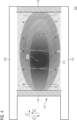
- Fig. 3 illustrates an exemplary heat (temperature) distribution 300 in the heat storage material 115 of the heat-transfer bed 110 of the exemplary fluid purification device 100 having the heat blocking elements 140, 150.
- the hottest zone is the center 310 of the heat-transfer bed 110. Due to heat losses at the thermally insulating wall 118, less heat would be stored at the lateral sides of the heat-transfer bed 110.
- a more even heat and temperature distribution in the heat-transfer bed 110 may be achieved such that the fluid 101 is sufficiently heated by the heat-transfer bed 110 irrespective of whether the fluid 101 flows through the center 310 or the lateral side portions 320 and 330 of the heat-transfer bed 110. Accordingly, no dedicated heating structure for heating the side portions of the heat-transfer bed 110 is needed. The total energy loss of the fluid purification device 100 may be reduced.
- Fig. 4 illustrates a prior art fluid purification device 400 not using heat blocking elements.
- the heat distribution 410 is uneven and causes an uneven temperature distribution in the heat-transfer bed 110.
- the hottest zone 420 is shifted towards the left side of the heat-transfer bed 110. Due to the losses at the thermally insulating wall 118, less heat is stored at the lateral edge portions of the heat-transfer bed 110. In particular, significantly less heat is stored in the right side portion of the heat-transfer bed 110. This may result in insufficient heating of the fluid 101 when passing the heat-transfer bed 110 and, hence, negatively affect the purification of the fluid 101.
- the heat distribution 410 illustrated in Fig. 4 is caused by the significantly different flow distribution of the fluid 101 in the fluid purification device 400.
- Fig. 5 illustrates the flow of the fluid 101 through the fluid purification device 400 during a time period in which the first plenum 120 is configured to supply the fluid 101 to the heat-transfer bed 110.
- the fluid 101 travels through the first plenum 101 substantially along the first spatial direction x 1 .
- the speed of the fluid 101 decreases along the first spatial direction x 1 as indicated in Fig. 5 by the size of the reference signs "V" depicted in the first plenum 120, which decreases from the left to the right.
- the static pressure of fluid 101 in the first plenum 120 increases along the first spatial direction x 1 .
- the increase of the static pressure of the fluid 101 entering the heat-transfer bed 110 along the first spatial direction x 1 is indicated in Fig. 5 by the size of the reference signs "P" depicted at the first opening 111, which increases along the first spatial direction x 1 (i.e. from the left to the right).
- the increasing static pressure along the first spatial direction x 1 causes a flow of the fluid 101 through the heat storage material of the heat-transfer bed 110 towards regions with lower static pressure.
- This causes an increase of the static pressure of the reacted fluid 101' leaving the heat-transfer bed 110 along the first spatial direction x 1 is indicated in Fig. 5 by the size of the reference signs "P" depicted at the second opening 112, which increases along the first spatial direction x 1 .
- the flow of the fluid 101 through the heat storage material of the heat-transfer bed 110 is oriented towards the left side of the heat-transfer bed 110 such that effectively less heat is stored in the heat storage material at the right side of the heat-transfer bed 110.
- heat released from the heat-transfer bed 110 via the first opening 111 may distribute over the entire first plenum and lead to additional heat losses.
- using the heating blocking element 140 and optionally further the heating blocking element 150 may improve heat loss and flow distribution of the fluid 101 compared to the fluid purification device 400.
- the surface 141 of the heat blocking element 140 extends substantially parallel to the first opening 111.
- the distance between the heat blocking element 140 and the boundary 113 / the heat-transfer bed 110 is selected such that the gap 160 acts as a nozzle for the fluid 101 when flowing from the first plenum 120 to the heat-transfer bed 110.
- the gap 160 acting as nozzle for the fluid 101 may allow to generate the above described flow distribution of the fluid 101 in the heat-transfer bed 110.
- the heat-transfer bed 110 may comprise one or more protrusion 114 (e.g. a ledge) formed at the boundary 113 of the first opening 111.
- the one or more protrusion 114 are optional and in general not necessary for defining the gap 160 between the surface 141 of the heat blocking element 140 and the boundary 113 of the first opening 111.
- the surface 151 of the heat blocking element 150 extends substantially parallel to the second opening 112.
- the distance between the heat blocking element 150 and the boundary 115 / the heat-transfer bed 110 is selected such that the gap 170 acts as a nozzle for the fluid 101 when flowing from the second plenum 130 to the heat-transfer bed 110.
- the gap 170 acting as nozzle for the fluid 101 may analogously allow to generate the above described flow distribution of the fluid 101 in the heat-transfer bed 110.
- the heat-transfer bed 110 may comprise one or more other protrusion 116 (e.g. a ledge) formed at the boundary 115 of the second opening 112.
- the one or more protrusion 116 are optional and in general not necessary for defining the gap 170 between the surface 151 of the heat blocking element 150 and the boundary 115 of the second opening 112.
- a plurality of recesses for passthrough of the fluid 101 may optionally be formed in the heat blocking element 140.
- the plurality of recesses extend from the surface 141 of the heat blocking element, which faces the first opening 111, to another opposite surface 142 of the heat blocking element 140, which faces the housing 121 of the first plenum 120.
- the plurality of recesses in the heat blocking element 140 may support the generation of the above described flow distribution of the fluid 101 in the heat-transfer bed 110.
- a respective size of the plurality of recesses for passthrough of the fluid 101 and/or a number of recesses for passthrough per unit area may increase along the first spatial direction x 1 .
- Increasing the respective size of the plurality of recesses for passthrough of the fluid 101 and/or the number of recesses for passthrough per unit area along the first spatial direction x 1 may allow to lower the effective resistance of the heat blocking element 140 for the fluid 101 when entering the heat-transfer bed 110 and, hence, support the generation of the above described flow distribution of the fluid 101 in the heat-transfer bed 110.
- the heat blocking element 140 may optionally comprise one or more surface structure for controlling a flow direction and/or flow characteristics of the fluid 101 locally.
- one or more of the surface 141 and the surface 142 may be structured for controlling the flow direction and/or the flow characteristics of the fluid 101 locally in order to support the generation of the above described flow distribution of the fluid 101 in the heat-transfer bed 110.
- one or more guide baffle and/or one or more orifice may be used as surface structures.
- another plurality of recesses for passthrough of the fluid 101 may optionally be formed in the heat blocking element 150.
- the plurality of recesses extend from the surface 151 of the heat blocking element, which faces the second opening 112, to another opposite surface 152 of the heat blocking element 150, which faces the housing 131 of the second plenum 130.
- the plurality of recesses in the heat blocking element 150 may support the generation of the above described flow distribution of the fluid 101 in the heat-transfer bed 110.
- the respective size of the plurality of recesses for passthrough of the fluid 101 and/or a number of recesses for passthrough per unit area may increase along the first spatial direction x 1 .
- the plurality of recesses in the heat blocking element 150 further allow the reacted fluid 101' to more easily leave the heat-transfer bed 110.
- the plurality of recesses in the heat blocking element 140 further allow the reacted fluid 101' to more easily leave the heat-transfer bed 110 as can be seen from Fig. 2 .
- Fig. 6 illustrates another fluid purification device 600 with tilted heat blocking elements. Fig. 6 illustrates the fluid purification device 600 during a time period in which the first plenum 120 is configured to supply the fluid 101 to the heat-transfer bed 110 and the second plenum 140 is configured to drain the reacted fluid 101' from the heat-transfer bed 110.
- the surface 141 of the heat blocking element 140 which faces the first opening 111, is tilted with respect to the first opening 111. Accordingly, a distance between the surface 141 of the heat blocking element 140 and the first opening 111 increases along the first spatial direction x 1 . Analogously, a distance between the opposite surface 142 of the heat blocking element 140 and a wall 122 of the first plenum's housing 121 decreases along the first spatial direction x 1 .
- the first opening 111 and the wall 122 of the first plenum's housing 121 are arranged on opposite sides of the heat blocking element 140.
- the surface 151 of the heat blocking element 150 which faces the second opening 112, may be tilted with respect to the second opening 112. Accordingly, a distance between the surface 151 of the heat blocking element 150 and the second opening 112 increases along the first spatial direction x 1 . Analogously, a distance between the opposite surface 152 of the heat blocking element 150 and a wall 132 of the second plenum's housing 131 decreases along the first spatial direction x 1 .
- the second opening 112 and the wall 132 of the second plenum's housing 131 are arranged on opposite sides of the heat blocking element 150.
- the tilted heat blocking elements 140 and 150 in the example of Fig. 6 may allow to improve heat loss and flow distribution of the fluid 101.
- the tilt angles of the heat blocking elements 140 and 150 with respect to the respective one of the first opening 111 and the second opening 112 may be identical to each other as illustrated in Fig. 6 .
- the present disclosure is not limited thereto. In other examples, different tilt angles may be used for the heat blocking elements 140 and 150.
- the heat blocking elements 140 and 150 do not comprise any moving parts. However, the present disclosure is not limited thereto. In the following, examples will be described with reference to Fig. 7 , Fig. 8 and Fig. 9 , in which the heat blocking element 140 comprises at least one respective movable element for adjusting the gap to the boundary of the respective opening 111.
- the respective fluid purification device is illustrated in each of Fig. 7 , Fig. 8 and Fig. 9 during a time period in which the first plenum 120 is configured to supply the fluid 101 to the heat-transfer bed 110 and the second plenum 140 is configured to drain the reacted fluid 101' from the heat-transfer bed 110.
- the heat blocking element 140 comprises two movable elements 144 and 145 for adjusting the gap 160 between the boundary 113 of the first opening 111 and at least part of the surface 141 of the heat blocking element 140.
- the two movable elements 144 and 145 are edge portions of the heat blocking element 140 coupled to a central portion 143 of the heat blocking element 140.
- the two movable elements 144 and 145 are movable with respect the central portion 143 of the heat blocking element 140.
- the heat blocking element 150 comprises two movable elements 154 and 155 for adjusting the gap 170 between the boundary 115 of the second opening 112 and at least part of the surface 151 of the heat blocking element 150.
- the two movable elements 154 and 155 are edge portions of the heat blocking element 150 coupled to a central portion 153 of the heat blocking element 150.
- the two movable elements 154 and 155 are movable with respect the central portion 153 of the heat blocking element 150.
- the heat blocking element 140 comprises one movable element 146 for adjusting the gap 160 between the boundary 113 of the first opening 111 and a part of the surface 141 of the heat blocking element 140.
- the movable element 146 is coupled to a static element 147 of the heat blocking element 140.
- the movable element 146 is movable with respect the static element 147 of the heat blocking element 140.
- the heat blocking element 150 comprises one movable element 156 for adjusting the gap 170 between the boundary 115 of the second opening 112 and a part of the surface 151 of the heat blocking element 150.
- the movable element 156 is coupled to a static element 157 of the heat blocking element 150.
- the movable element 156 is movable with respect the static element 157 of the heat blocking element 150.
- the heat blocking element 140 comprises two movable elements 148 and 149 for adjusting the gap 160 between the boundary 113 of the first opening 111 and the surface 141 of the heat blocking element 140.
- the two movable elements 148 and 149 are coupled to and moveable with respect to each other.
- the heat blocking element 150 comprises two movable elements 158 and 159 for adjusting the gap 170 between the boundary 115 of the second opening 112 and the surface 151 of the heat blocking element 150.
- the two movable elements 158 and 159 are coupled to and moveable with respect to each other.
- the heat blocking element 140 in each of the fluid purification devices 700, 800 and 900 illustrated Fig. 7 , Fig. 8 and Fig. 9 comprises at least one movable element for adjusting the gap 160 between the boundary 113 of the first opening 111 and at least part of the surface 141 of the heat blocking element 140.
- the heat blocking element 150 in each of the fluid purification device 700, 800 and 900 comprises at least one movable element for adjusting the gap 170 between the boundary 115 of the second opening 112 and at least part of the surface 151 of the heat blocking element 150.
- each of the fluid purification devices 700, 800 and 900 may further comprise at least one actuator (not illustrated) coupled to the at least one movable element of the heat blocking element 140.
- the at least one actuator is configured to adjust a respective positioning and/or orientation of the at least one movable element of the heat blocking element 140 relative to the boundary 113 of the first opening 111.
- each of the fluid purification devices 700, 800 and 900 may further comprise at least one further actuator (not illustrated) coupled to the at least one movable element of the heat blocking element 150.
- the at least one actuator is configured to adjust a respective positioning and/or orientation of the at least one movable element of the heat blocking element 150 relative to the boundary 115 of the second opening 112.
- the variation of the static pressure at the first opening 111 may be adjusted (controlled) along the first spatial direction x 1 in order to support the generation of the above described flow distribution of the fluid 101 in the heat-transfer bed 110.
- the variation of the static pressure at the second opening 112 may be adjusted (controlled) along the first spatial direction x 1 by varying the distance of the at least one movable element of the heat blocking element 150 relative to the boundary 115 of the second opening 112.
- the at least one actuator for varying the distance of the at least one movable element of the heat blocking element 140 relative to the boundary 113 of the first opening 111 may, e.g., comprise a hydraulic system and/or a combination of an electric motor and a drive system for moving the at least one movable element of the heat blocking element 140.
- the heat blocking element 150 may be implemented analogously.
- the at least one actuator for varying the distance of the at least one movable element of the heat blocking element 140 relative to the boundary 113 of the first opening 111 may, e.g., be configured to adjust the distance of the at least one movable element of the heat blocking element 140 relative to the boundary 113 of the first opening 111 based on a temperature and/or a pressure and/or a differential pressure in the first plenum 120 as these quantities affect the variation of the static pressure at the first opening 111.
- the at least one actuator for varying the distance of the at least one movable element of the heat blocking element 140 relative to the boundary 113 of the first opening 111 may, e.g., be configured to adjust the distance of the at least one movable element of the heat blocking element 140 relative to the boundary 113 of the first opening 111 time based and/or event based.
- the distance may be varied in a time period directly before or after changing the overall fluid direction inside the first plenum 120 and the second plenum130, or in case of exceptional events such as concentration peaks or downs in the fluid (e.g. a gas stream) entering the fluid purification device.
- the at least one actuator for varying the distance of the at least one movable element of the heat blocking element 150 relative to the boundary 115 of the second opening 112 may, e.g., be configured to adjust the distance of the at least one movable element of the heat blocking element 150 relative to the boundary 115 of the second opening 112 based on a temperature and/or a pressure and/or a differential pressure in the second plenum 130 (as these quantities affect the variation of the static pressure at the second opening 112) and/or time based and/or event based.
- the at least one actuator for varying the distance of the at least one movable element of the heat blocking element 140 relative to the boundary 113 of the first opening 111 and the at least one actuator for varying the distance of the at least one movable element of the heat blocking element 150 relative to the boundary 115 of the second opening 112 may comprise or be coupled to one or more control circuitry for controlling the operation of the respective at least one actuator based on the temperature and/or the pressure and/or the differential pressure in the respective plenum and/or time based and/or event based.
- the respective fluid purification device may comprise one or more sensor coupled to the one or more control circuitry and configured to measure the temperature and/or the pressure and/or the differential pressure in the respective plenum.
- the one or more control circuitry may be a single dedicated processor, a single shared processor, or a plurality of individual processors, some of which or all of which may be shared, a digital signal processor (DSP) hardware, an application specific integrated circuit (ASIC), or a field programmable gate array (FPGA).
- DSP digital signal processor
- ASIC application specific integrated circuit
- FPGA field programmable gate array
- the one or more control circuitry may optionally be coupled to, e.g., read only memory (ROM) for storing software (e.g. storing a program for controlling the respective at least one actuator), random access memory (RAM) and/or non-volatile memory.
- Fig. 10 illustrates another exemplary fluid purification device 1000 using bendable heat blocking elements.
- the fluid purification device 1000 is illustrated in Fig. 10 during a time period in which the first plenum 120 is configured to supply the fluid 101 to the heat-transfer bed 110 and the second plenum 140 is configured to drain the reacted fluid 101' from the heat-transfer bed 110.
- the heat blocking element 140 is bendable.
- the heat blocking element 140 comprises one or more bimetal structure configured to bend the heat blocking element based on a temperature in the first plenum 120 for adjusting the gap 160 between the boundary 113 of the first opening 111 and at least part of the surface 141 of the heat blocking element 140.
- the whole heat blocking element 140 may be formed as a bimetal structure for obtaining the temperature sensitive bending.
- one or more bimetal structure may be formed in or on the heat blocking element 140 for obtaining the temperature sensitive bending.
- the variation of the static pressure at the first opening 111 may be adjusted (controlled) along the first spatial direction x 1 in order to support the generation of the above described flow distribution of the fluid 101 in the heat-transfer bed 110.
- the heat blocking element 150 is bendable for adjusting the gap 170 between the boundary 115 of the second opening 112 and at least part of the surface 151 of the heat blocking element 150.
- the heat blocking element 150 may at least in part be formed of a bendable/flexible material (e.g. the heat blocking element 150 may at least in part be formed of plastics, carbon, glass fiber, metal (e.g. spring steel) or mixtures, composite, laminates thereof - analogous to what is described above for the heat blocking element 140)).
- the fluid purification device further comprises at least one actuator 180 configured to exert a force on the heat blocking element 150 for bending the heat blocking element 150.
- the at least one actuator 180 exerts the force for bending the heat blocking element 150 on the other end of the heat blocking element 150.
- the at least one actuator 180 exerts a lateral force on the heat blocking element 150.
- the present disclosure is not limited thereto.
- the at least one actuator 180 may exert the force on the heat blocking element 150 along a spatial direction, which is substantially perpendicular to the surface 151 of the heat blocking element 150 when the heat blocking element 150 is not bent (e.g. along the third spatial direction x 3 ).
- both ends of the heat blocking element 150 may be fixed.
- the at least one actuator 180 may, e.g., be a stamp. However, it is to be noted that the present disclosure is not limited thereto. In general, any means that can be driven by, e.g., a hydraulic system or a (e.g. electric) motor to exert a force on the heat blocking element 150 may be used.
- the heat blocking element 150 may be based on a bimetal structure.
- the heat blocking element 150 may comprise one or more bimetal structure configured to bend the heat blocking element 150 based on a temperature in the second plenum 130 for adjusting the gap 170 between the boundary 115 of the second opening 112 and at least part of the surface 151 of the heat blocking element 150.
- the heat blocking element 140 may be bent by at least one actuator.
- the heat blocking element 140 may be bendable for adjusting the gap 160 between the boundary 113 of the first opening 111 and at least part of the surface 141 of the heat blocking element 140.
- the fluid purification device may further comprise at least one actuator configured to exert a force on the heat blocking element 140 for bending the heat blocking element 140.
- the respective at least one actuator for exerting the respective force on the respective one of the heat blocking element 140 and the heat blocking element 150 may be configured to exert the respective force based one a temperature and/or a pressure and/or a differential pressure in the respective one of first plenum 120 and the second plenum 130 as these quantities affect the variation of the static pressure at the respective one of the first opening 111 and the second opening 112.
- the respective at least one actuator for exerting the respective force on the respective one of the heat blocking element 140 and the heat blocking element 150 may be configured to exert the respective force time based and/or event based.
- the respective at least one actuator may change the force exerted on the respective one of the heat blocking element 140 and the heat blocking element 150 during a time period directly before or after changing the overall fluid direction inside the first plenum 120 and the second plenum130, or in case of exceptional events such as concentration peaks or downs in the fluid (e.g. a gas stream) entering the fluid purification device.
- the respective at least one actuator may comprise or be coupled to one or more control circuitry for controlling the operation of the respective at least one actuator based on the temperature and/or the pressure and/or the differential pressure in the respective plenum and/or time based and/or event based - analogously to what is described above with respect to Fig. 9 .
- the heat blocking elements 140 and 150 are plate-shaped. However, the present disclosure is not limited thereto. In general, the heat blocking elements 140 and 150 may exhibit any suitable shape.
- Fig. 11 illustrates another exemplary fluid purification device 1100 using wedge-shaped heat blocking elements 140 and 150. The fluid purification device 1100 is illustrated in Fig. 11 during a time period in which the first plenum 120 is configured to supply the fluid 101 to the heat-transfer bed 110 and the second plenum 140 is configured to drain the reacted fluid 101' from the heat-transfer bed 110.
- the surface 141 of the heat blocking element 140 extends substantially parallel to the first opening 111 such that the gap 160 formed between the boundary 113 of the first opening 111 and the surface 141 of the heat blocking element 140 acts as a nozzle for the fluid 101 when flowing from the first plenum 120 to the heat-transfer bed 110.
- the opposite surface 142 of the heat blocking element 140 faces the wall 122 of the first plenum's housing 121. Due to the wedge-shape of the heat blocking element 140, a distance between the surface 141 and the other surface 142 of the heat blocking element increases along the first spatial direction x 1 , and a distance between the surface 142 of the heat blocking element 140 and the wall 122 of the first plenum's housing 121 decreases along the first spatial direction x 1 .
- the volume of the first plenum 120 for the fluid 120 decrease along the first spatial direction x 1 .
- the decrease in volume along the first spatial direction x 1 allows to compensate for the decrease in speed of the fluid 101 along the first spatial direction x 1 .
- the variation of the static pressure at the first opening 111 may be adjusted along the first spatial direction x 1 in order to support the generation of the above described flow distribution of the fluid 101 in the heat-transfer bed 110.
- the other heat-blocking element 150 may be shaped analogously as illustrated in Fig. 11 . That is, the surface 151 of the heat blocking element 150 extends substantially parallel to the second opening 112 such that the gap 170 formed between the boundary 115 of the second opening 112 and the surface 151 of the heat blocking element 150 acts as a nozzle for the fluid 101.
- the opposite surface 152 of the heat blocking element 150 faces the wall 132 of the second plenum's housing 131.
- a distance between the surface 151 and the other surface 152 of the heat blocking element 150 increases along the first spatial direction x 1
- a distance between the surface 152 of the heat blocking element 150 and the wall 122 of the second plenum's housing 131 decreases along the first spatial direction x 1 .
- the heat blocking elements 140 and 150 exhibit a wedge shape.
- the present disclosure is not limited thereto. In general any shape causing that the distance between the surface 141 and the other surface 142 of the heat blocking element 140 increases along the first spatial direction x 1 , and that the distance between the surface 142 of the heat blocking element 140 and the wall 122 of the first plenum's housing 121 decreases along the first spatial direction x 1 may be used for the heat blocking element 140.
- a nonlinear increase of the distance between the surface 141 and the other surface 142 of the heat blocking element 140 may be used.
- the first plenum 120 and the second plenum 130 extend lengthwise along the first spatial direction x 1 such that the fluid 101 travels along the along the first spatial direction x 1 while the respective one of the first plenum 120 and the second plenum 130 is configured to supply the fluid 101 to the heat-transfer bed 110.
- the present disclosure is not limited thereto.
- the first plenum 120 and the second plenum 130 may extend lengthwise along different spatial directions.
- the first plenum 120 and the second plenum 130 may extend lengthwise along anti-parallel spatial directions. This is exemplarily illustrated in Fig. 12. Fig.
- FIG. 12 illustrates another exemplary fluid purification device 1200 during a time period in which the first plenum 120 is configured to supply the fluid 101 to the heat-transfer bed 110 and the second plenum 140 is configured to drain the reacted fluid 101' from the heat-transfer bed 110.
- Fig. 12 is based on the example described above with respect to Fig. 1 and Fig. 2 , contrary to the above example, the second plenum 130 extends along a fourth spatial direction x 4 , which is anti-parallel to the first spatial direction x 1 . Accordingly, unlike in the above examples, the reacted fluid 101' does not travel through the second plenum 130 along the fourth spatial direction x 4 during a time period in which the second plenum 130 is configured to drain the reacted fluid 101' from the heat-transfer bed 110. Instead, the reacted fluid 101' travels through the second plenum 130 along the first spatial direction x 1 .
- the fluid 101 does not travel through the second plenum 120 along the first spatial direction x 1 but along the anti-parallel fourth spatial direction x 4 .
- first plenum 120 and the second plenum 130 may also in the above described examples extend lengthwise along different spatial directions.
- first plenum 120 and the second plenum 130 may also in the above described examples extend lengthwise along anti-parallel spatial directions similar to the example of Fig. 12 .
- the positioning and/or orientation of the heat blocking element 150 in the second plenum 130 may be adjusted/changed accordingly (e.g. the positioning and/or orientation of the heat blocking element 150 may be with respect to the fourth spatial direction x 4 instead of the first spatial direction x 1 as described above).
- the heat blocking element 140 may also in the examples of Figs. 6 to 12 optionally comprise a plurality of recesses for passthrough of the fluid 101 and/or one or more surface structure for controlling a flow direction and/or flow characteristics of the fluid 101 locally - analogously to what is described with respect to the example of Fig. 1 and Fig. 2 .
- the heat blocking element 150 may also in the examples of Figs. 6 to 12 optionally comprise a plurality of recesses for passthrough of the fluid 101 and/or one or more surface structure for controlling a flow direction and/or flow characteristics of the fluid 101 locally - analogously to what is described with respect to the example of Fig. 1 and Fig. 2 .
- the heat blocking element 150 may also in the examples of Figs. 6 to 12 optionally comprise a plurality of recesses for passthrough of the fluid 101 and/or one or more surface structure for controlling a flow direction and/or flow characteristics of the fluid 101 locally - analogously to what is described with respect to the example of Fig. 1 and
- the examples described with respect to Figs. 7 to 10 may each comprise at least one actuator coupled to the heat blocking element for moving one or more movable object or exerting a bending force on the respective heat blocking element 140 or 150.
- the respective fluid purification device may comprise at least one actuator coupled to the heat blocking element 140 and configured to adjust a positioning and/or orientation of the heat blocking element 140's surface 141 with respect to the first opening 111. For example, distance of the heat blocking element 140's surface 141 with respect to the first opening 111 may be adjusted to tune the nozzle-effect of the gap 160.
- a tilt angle of the heat blocking element 140's surface 141 with respect to the first opening 111 may be adjusted.
- the tilt angle of the heat blocking element 140's surface 141 with respect to the first opening 111 may be changed such that the orientation of the heat blocking element 140's surface 141 illustrated in Fig. 1 is changed to the orientation of the heat blocking element 140's surface 141 illustrated in Fig. 6 .
- the respective fluid purification device may comprise at least one actuator coupled to the heat blocking element 150 and configured to adjust a positioning and/or orientation of the heat blocking element 150's surface 151 with respect to the second opening 112.
- the respective at least one actuator for adjusting the positioning and/or orientation of the respective one of the heat blocking element 140 and the heat blocking element 150 may be configured to adjust the respective positioning and/or orientation based on a temperature and/or a pressure and/or a differential pressure in the respective one of the first plenum 120 and the second plenum 130 as these quantities affect the variation of the static pressure at the respective one of the first opening 111 and the second opening 112.
- the respective at least one actuator for adjusting the positioning and/or orientation of the respective one of the heat blocking element 140 and the heat blocking element 150 may be configured to adjust the respective positioning and/or orientation time based and/or event based.
- the respective at least one actuator may change the respective positioning and/or orientation of the heat blocking element 140 and the heat blocking element 150 during a time period directly before or after changing the overall fluid direction inside the first plenum 120 and the second plenum130, or in case of exceptional events such as concentration peaks or downs in the fluid (e.g. a gas stream) entering the fluid purification device.
- the respective at least one actuator may comprise or be coupled to one or more control circuitry for controlling the operation of the respective at least one actuator based on the temperature and/or the pressure and/or the differential pressure in the respective plenum and/or time based and/or event based - analogously to what is described above with respect to Fig. 9 .
- Fig. 13 illustrates a flowchart of a method 1300 for operating a fluid purification device according to the present disclosure.
- the method 1300 comprises supplying 1302 fluid to the heat-transfer bed alternatingly through the first plenum and the second plenum such that the fluid heats up and reacts while flowing through the heat storage material. Additionally, the method 1300 comprises, during a time period in which one of the first plenum and the second plenum supplies the fluid to the heat-transfer bed, draining 1304 the reacted fluid from the heat-transfer bed through the other one of the first plenum and the second plenum.
- the method 1300 may enable improved purification of the fluid compared to conventional approaches.
- the heat blocking element in the first plenum may allow to reduce heat loses at the first opening of the heat-transfer bed.
- the heat blocking element in the first plenum may allow for an improved flow distribution of the fluid over the heat-transfer bed such that a more even temperature distribution in the heat-transfer bed may be achieved.
- the method 1300 may comprise one or more additional optional feature corresponding to one or more aspect of the proposed technique or one or more example described above.
- aspects described in relation to a device or system should also be understood as a description of the corresponding method.
- a block, device or functional aspect of the device or system may correspond to a feature, such as a method step, of the corresponding method.
- aspects described in relation to a method shall also be understood as a description of a corresponding block, a corresponding element, a property or a functional feature of a corresponding device or a corresponding system.
Landscapes
- Engineering & Computer Science (AREA)
- Chemical & Material Sciences (AREA)
- General Engineering & Computer Science (AREA)
- Mechanical Engineering (AREA)
- Chemical Kinetics & Catalysis (AREA)
- Environmental & Geological Engineering (AREA)
- General Chemical & Material Sciences (AREA)
- Physics & Mathematics (AREA)
- Thermal Sciences (AREA)
- Health & Medical Sciences (AREA)
- Combustion & Propulsion (AREA)
- Biomedical Technology (AREA)
- Analytical Chemistry (AREA)
- Oil, Petroleum & Natural Gas (AREA)
- Toxicology (AREA)
- Physical Or Chemical Processes And Apparatus (AREA)
- Devices And Processes Conducted In The Presence Of Fluids And Solid Particles (AREA)
- Steam Or Hot-Water Central Heating Systems (AREA)
- Heat-Exchange Devices With Radiators And Conduit Assemblies (AREA)
Abstract
Description
- The present disclosure relates to purification of fluids. In particular, examples of the present disclosure relate to a fluid purification device and a method for operating a fluid purification device. More specifically, the present disclosure refers to a regenerative fluid purification device and a method for operating such a device.
- Conventional systems using a heat-transfer bed filled with ceramic material for exhaust gas purification suffer from various heat loses such as heat losses at the side walls of the heat-transfer bed or at the inlets and outlets of the heat-transfer bed for the exhaust gas. Additionally, such conventional systems suffer from a spatially varying pressure drop at the inlets of the heat-transfer bed for the exhaust gas. As a consequence, the flow distribution of the exhaust gas over the heat-transfer bed is uneven and causes an uneven temperature distribution in the heat-transfer bed, which may result in insufficient heating of the exhaust gas when passing the heat-transfer bed and, hence, negatively affect the purification of the exhaust gas.
- There may be demand for improved purification of fluids such as exhaust gases.
- The demand may be satisfied by the subject-matter of the appended claims.
- According to a first aspect, the present disclosure provides a fluid purification device. The fluid purification device comprises a heat-transfer bed filled with heat storage material. Further, the fluid purification device comprises a first plenum attached to a first opening of the heat-transfer bed, and a second plenum attached to a second opening of the heat-transfer bed. The first opening and the second opening are arranged on opposite sides of the heat-transfer bed. Additionally, the fluid purification device comprises a heat blocking element arranged in the first plenum. The heat blocking element is spaced apart from the heat-transfer bed and is spaced apart from a housing of the first plenum. The heat blocking element extends beyond the first opening and is configured to limit heat emission from the heat storage material into the first plenum. The first plenum and the second plenum are configured to alternatingly supply fluid to the heat-transfer bed such that the fluid heats up and reacts while flowing through the heat storage material. During a time period in which one of the first plenum and the second plenum is configured to supply the fluid to the heat-transfer bed, the other one of the first plenum and the second plenum is configured to drain the reacted fluid from the heat-transfer bed.
- According to a second aspect, the present disclosure provides a method for operating the above fluid purification device. The method comprises supplying fluid to the heat-transfer bed alternatingly through the first plenum and the second plenum such that the fluid heats up and reacts while flowing through the heat storage material. Additionally, the method comprises, during a time period in which one of the first plenum and the second plenum supplies the fluid to the heat-transfer bed, draining the reacted fluid from the heat-transfer bed through the other one of the first plenum and the second plenum.
- The heat blocking element in the first plenum may allow to reduce heat loses at the first opening of the heat-transfer bed. Furthermore, the heat blocking element in the first plenum may allow for an improved flow distribution of the fluid over the heat-transfer bed such that a more even temperature distribution in the heat-transfer bed may be achieved. As a consequence, the purification of the fluid may be improved compared to conventional approaches.
- According to some examples of the present disclosure, the fluid purification device further comprises another heat blocking element arranged in the second plenum. The other heat blocking element is spaced apart from the heat-transfer bed and is spaced apart from a housing of the second plenum. The other heat blocking element extends beyond the second opening and is configured to limit heat emission from the heat storage material into the second plenum. The other heat blocking element in the second plenum may allow to reduce heat loses at the second opening of the heat-transfer bed. Furthermore, the other heat blocking element in the second plenum may allow to further improve the flow distribution of the fluid over the heat-transfer bed such that a more even temperature distribution in the heat-transfer bed may be achieved. As a consequence, the purification of the fluid may be further improved compared to conventional approaches.
- In some examples of the present disclosure, a gap formed between a boundary of the first opening and a surface of the heat blocking element facing the first opening acts as a nozzle for the fluid when flowing from the first plenum to the heat-transfer bed. This exemplary configuration may allow to support the generation of the improved flow distribution of the fluid in the heat-transfer bed.
- According to some examples of the present disclosure, the surface of the heat blocking element extends substantially parallel to the first opening. This exemplary configuration may allow to define the width of the gap and, hence, to adjust the nozzle effect of the gap.
- In some examples of the present disclosure, the heat-transfer bed comprises one or more protrusion formed at the boundary of the first opening for defining the gap between the surface of the heat blocking element and the boundary of the first opening. The one or more protrusion may allow to define the width of the gap and, hence, to adjust the nozzle effect of the gap.
- According to some examples of the present disclosure, the heat blocking element comprises at least one movable element for adjusting the gap between the boundary of the first opening and at least part of the surface of the heat blocking element. In these examples, the fluid purification device further comprises at least one actuator configured to adjust, based on a temperature and/or a pressure and/or a differential pressure in the first plenum and/or time based and/or event based, a respective positioning and/or orientation of the at least one movable element relative to the boundary of the first opening. Changing the positioning and/or orientation of the at least one movable element relative to the boundary of the first opening may allow to adjust (control) the variation of the static pressure at the first opening in order to support the generation of the improved flow distribution of the fluid in the heat-transfer bed.
- In alternative examples of the present disclosure, the heat blocking element is bendable for adjusting the gap between the boundary of the first opening and at least part of the surface of the heat blocking element. In these examples, the fluid purification device further comprises at least one actuator configured to exert, based on a temperature and/or a pressure and/or a differential pressure in the first plenum and/or time based and/or event based, a force on the heat blocking element for bending the heat blocking element. Adjusting the gap by bending the heat blocking element may allow to adjust (control) the variation of the static pressure at the first opening in order to support the generation of the improved flow distribution of the fluid in the heat-transfer bed.
- In further alternative examples of the present disclosure, the heat blocking element comprises a bimetal structure configured to bend the heat blocking element based on a temperature in the first plenum for adjusting the gap between the boundary of the first opening and at least part of the surface of the heat blocking element. Adjusting the gap by means of the bimetal structure may allow to adjust (control) the variation of the static pressure at the first opening in order to support the generation of the improved flow distribution of the fluid in the heat-transfer bed.
- According to some examples of the present disclosure, a surface of the heat blocking element facing the first opening is tilted with respect to the first opening. In these examples, the first plenum extends lengthwise along a first spatial direction such that the fluid travels through the first plenum along the first spatial direction during a time period in which the first plenum is configured to supply the fluid to the heat-transfer bed. A distance between the surface of the heat blocking element and the first opening increases along the first spatial direction. A distance between another opposite surface of the heat blocking element and a wall of the first plenum's housing decreases along the first spatial direction. The first opening and the wall of the first plenum's housing are arranged on opposite sides of the heat blocking element. Also this exemplary configuration may allow to support the generation of the improved flow distribution of the fluid in the heat-transfer bed.
- In some examples of the present disclosure, the heat blocking element is substantially plate-shaped. The plate-shaped may allow simple implementation of the heat blocking element.
- According to some examples of the present disclosure, the heat blocking element comprises another opposite surface facing a wall of the first plenum's housing. In these examples, the first opening and the wall of the first plenum's housing are arranged on opposite sides of the heat blocking element. The first plenum extends lengthwise along a first spatial direction such that the fluid travels through the first plenum along the first spatial direction during a time period in which the first plenum is configured to supply the fluid to the heat-transfer bed. A distance between the surface and the other surface of the heat blocking element increases along the first spatial direction. A distance between the other surface of the heat blocking element and the wall of the first plenum's housing decreases along the first spatial direction. Also this exemplary configuration may allow to support the generation of the improved flow distribution of the fluid in the heat-transfer bed.
- In some examples of the present disclosure, the fluid purification device further comprises at least one actuator coupled to the heat blocking element. In these examples, the at least one actuator is configured to adjust, based on a temperature and/or a pressure and/or a differential pressure in the first plenum and/or time based and/or event based, a positioning and/or orientation of the heat blocking element's surface with respect to the first opening. Changing the positioning and/or orientation of the heat blocking element's surface may allow to adjust (control) the variation of the static pressure at the first opening in order to support the generation of the improved flow distribution of the fluid in the heat-transfer bed.
- According to some examples of the present disclosure, a plurality of recesses for passthrough of the fluid are formed in the heat blocking element. The plurality of recesses extend from a surface of the heat blocking element facing the first opening to another opposite surface of the heat blocking element. The plurality of recesses may allow to support the generation of the improved flow distribution of the fluid in the heat-transfer bed.
- In some examples of the present disclosure, the first plenum extends lengthwise along a first spatial direction such that the fluid travels through the first plenum along the first spatial direction during a time period in which the first plenum is configured to supply the fluid to the heat-transfer bed. In these examples, a respective size of the plurality of recesses for passthrough of the fluid and/or a number of recesses for passthrough per unit area increases along the first spatial direction. This exemplary configuration may allow to lower the effective resistance of the heat blocking element for the fluid when entering the heat-transfer bed and, hence, support the generation of the improved flow distribution of the fluid in the heat-transfer bed.
- According to some examples of the present disclosure, the heat blocking element comprises one or more surface structure for controlling a flow direction and/or flow characteristics of the fluid locally. The one or more surface structure may allow to support the generation of the improved flow distribution of the fluid in the heat-transfer bed.
- In some examples of the present disclosure, the other heat blocking element arranged in the second plenum may comprise one or more of the other features, or a selection of features as disclosed for the heat blocking element arranged in the first plenum as described in the sections above. In some preferred embodiments, the heat blocking element and the other heat blocking element are very much similar, analogous, identical and/or symmetric in their construction and features, especially the features disclosed for the heat blocking element in the sections above, to allow for an oscillating operation of the fluid purification device, by which one of the first and second plenum serves as entry whereas the other serves as exit for a fluid to be processed in the heat-transfer bed of the fluid purification device in alternating states/phases of operation.
- In some examples of the present disclosure, the fluid purification device further comprises an electrical heater configured to heat the heat storage material to a predefined temperature. The electrical heater may allow to initially heat the ceramic material to the predefined temperature.
- According to some examples of the present disclosure, catalyst material for lowering a reaction temperature of the fluid is arranged within the heat-transfer bed. Due to the catalyst material, the needed temperature for the reaction of the fluid may be lowered such that the fluid purification device may operate at lower temperatures.
- In some examples of the present disclosure, the heat-transfer bed comprises a thermally insulating wall surrounding the heat storage material and extending between the first plenum and the second plenum. In these examples, the first opening and the second opening are formed in the thermally insulating wall. The thermally insulating wall may allow to minimize heat losses over the heat-transfer bed.
- According to some examples of the present disclosure, the housing of the first plenum is at least partly formed of and/or is at least partly covered by a heat-insulating material. The heat-insulating material may allow to minimize heat loses over the housing of the first plenum.
- Some examples of apparatuses and/or methods will be described in the following by way of example only, and with reference to the accompanying figures, in which
-
Fig. 1 andFig. 2 illustrate a sectional view of a first example of a fluid purification device; -
Fig. 3 illustrates an exemplary heat distribution in the first example of the fluid purification device; -
Fig. 4 illustrates an exemplary heat distribution in a prior art fluid purification device without heat blocking elements; -
Fig. 5 illustrates an exemplary fluid flow in a prior art fluid purification device without heat blocking elements; -
Fig. 6 illustrates a sectional view of a second example of a fluid purification device; -
Fig. 7 illustrates a sectional view of a third example of a fluid purification device; -
Fig. 8 illustrates a sectional view of a fourth example of a fluid purification device; -
Fig. 9 illustrates a sectional view of a fifth example of a fluid purification device; -
Fig. 10 illustrates a sectional view of a sixth example of a fluid purification device; -
Fig. 11 illustrates a sectional view of a seventh example of a fluid purification device; -
Fig. 12 illustrates a sectional view of an eighth example of a fluid purification device; and -
Fig. 13 illustrates a flowchart of an example of a method for operating a fluid purification device as described herein. - Some examples are now described in more detail with reference to the enclosed figures. However, other possible examples are not limited to the features of these embodiments described in detail. Other examples may include modifications of the features as well as equivalents and alternatives to the features. Furthermore, the terminology used herein to describe certain examples should not be restrictive of further possible examples.
- Throughout the description of the figures same or similar reference numerals refer to same or similar elements and/or features, which may be identical or implemented in a modified form while providing the same or a similar function. The thickness of lines, layers and/or areas in the figures may also be exaggerated for clarification.
- When two elements A and B are combined using an "or", this is to be understood as disclosing all possible combinations, i.e. only A, only B as well as A and B, unless expressly defined otherwise in the individual case. As an alternative wording for the same combinations, "at least one of A and B" or "A and/or B" may be used. This applies equivalently to combinations of more than two elements.
- If a singular form, such as "a", "an" and "the" is used and the use of only a single element is not defined as mandatory either explicitly or implicitly, further examples may also use several elements to implement the same function. If a function is described below as implemented using multiple elements, further examples may implement the same function using a single element or a single processing entity. It is further understood that the terms "include", "including", "comprise" and/or "comprising", when used, describe the presence of the specified features, integers, steps, operations, processes, elements, components and/or a group thereof, but do not exclude the presence or addition of one or more other features, integers, steps, operations, processes, elements, components and/or a group thereof.
-
Fig. 1 andFig. 2 schematically illustrate a sectional view of afluid purification device 100 for purifying afluid 101. The fluid 101 may be or comprise one or more gaseous components or substances, one or more vapor components or substances, one or more liquid components or substances, and/or mixtures thereof. According to examples of the present disclosure, the fluid 101 may comprise exclusively gaseous components or substances. For example, the fluid 101 may be an exhaust gas or an exhaust air, wherein an exhaust air contains a higher proportion of oxygen compared to an exhaust gas. Thefluid purification device 100 removes one or more impurity and/or one or more pollutant from the fluid 101 for purifying thefluid 101. An impurity may be understood in this context as a substance in the fluid 101 that is not included in a desired (target) composition of thefluid 101. A pollutant may be understood in this context as a substance that harms systems, animals, humans and/or the environment when occurring in a specific quantity or concentration (e.g. defined as mass of the pollutant per unit volume of the fluid 101 or as number of pollutant particles per unit volume of the fluid 101). One or more impurity or pollutant contained in the fluid 101 may be combustible. For example, organic and/or inorganic impurities or pollutants may be removed from the fluid 101 by thefluid purification device 100. The organic and/or inorganic impurities or pollutants may, e.g., be Volatile Organic Compounds (VOCs), solvents, nitrogen oxides (NOx), methane (CH4), sulfur oxides (SOx), hydrogen fluoride (HF), ammonia (NH3), hydrogen chloride (HCl), dioxins, furans or pollutants of the basic structure CxHyOz (C denotes carbon; H denotes hydrogen; O denotes oxygen; x, y, and z are natural numbers). - The
fluid purification device 100 comprises a (e.g. single, i.e., exactly/only one) heat-transfer bed 110 filled with heat storage material (heat transfer material) 115. Theheat storage material 115 is material capable of storing and releasing heat. The heat storage material exhibits a certain (predefined) specific heat capacity and preferably a certain (predefined) heat transfer and/or transmission coefficient. For example, theheat storage material 115 may comprise or be ceramic material such as alumina porcelain, mullite, fireclay (chamotte), cordierite, zircon or a mixture thereof. However, the present disclosure is not limited thereto. Other types of ceramic material may be used as well. In some example, theheat storage material 115 may alternatively or additionally comprise or be concrete, stone, rock, metallic material or a mixture thereof. Theheat storage material 115 may be packed structured or randomly in the heat-transfer bed 110 to form regular or irregular patterns (e.g. ceramic honeycombs, ceramic saddles or the like may be used). - The heat-
transfer bed 110 comprises a thermally insulatingwall 118 surrounding theheat storage material 115. A first opening 111 and asecond opening 112 are formed in the thermally insulatingwall 118. Afirst plenum 120 is attached to the first opening 111 of the heat-transfer bed 110, and asecond plenum 130 is attached to thesecond opening 112 of the heat-transfer bed 110. The first opening 111 and thesecond opening 112 are arranged on opposite sides of the heat-transfer bed 110 such that the thermally insulatingwall 118 extends between thefirst plenum 120 and thesecond plenum 130. - The
first plenum 120 and thesecond plenum 130 are configured to alternatingly supply the fluid 101 to the heat-transfer bed 110 such that the fluid 101 heats up and reacts while flowing through theheat storage material 110. For example, the fluid 101 may be heat up and be subject to an oxidation process or a reduction process while flowing through theheat storage material 115. Theheat storage material 115 is configured to store heat released by the fluid 101 during and/or after the reaction. During a time period in which one of thefirst plenum 120 and thesecond plenum 130 is configured to supply the fluid 101 to the heat-transfer bed 110, the other one of thefirst plenum 120 and thesecond plenum 130 is configured to drain the reacted fluid 101' (i.e. the fluid after undergoing the reaction) from the heat-transfer bed 110. Accordingly, a flow direction of the fluid 101 through theheat storage material 115 is periodically reversed (e.g. every 90 to 120 seconds). -
Fig. 1 illustrates thefluid purification device 100 during a time period in which thefirst plenum 120 is configured to supply the fluid 101 to the heat-transfer bed 110 and thesecond plenum 130 is configured to drain the reacted fluid 101' from the heat-transfer bed 110. Accordingly, the fluid 101 flows from the top to the bottom of the heat-transfer bed 110 through theheat storage material 115. Heat energy previously stored in the top part of theheat storage material 115 is used to heat up the fluid 101 and causes the fluid 101 to react. Theheat storage material 115 at the bottom part recovers the excess heat energy from the reacted fluid 101'. For example, as the fluid 101 passes from the top part to the bottom part of theheat storage material 115, VOCs in the fluid 101 may get hot enough to undergo thermal oxidation to water vapor and carbon dioxide. -
Fig. 2 illustrates thefluid purification device 100 during a time period in which thesecond plenum 130 is configured to supply the fluid 101 to the heat-transfer bed 110 and thefirst plenum 120 is configured to drain the reacted fluid 101' from the heat-transfer bed 110. - Accordingly, the fluid 101 flows from the bottom to the top of the heat-
transfer bed 110 through theheat storage material 115. Heat energy previously stored in the bottom part of theheat storage material 115 is used to heat up the fluid 101 and causes the fluid 101 to react. Theheat storage material 115 at the top part recovers the heat energy from the reacted fluid 101'. - The periodic reversion of the flow direction of the fluid 101 through the
heat storage material 115 may allow to maintain a high heat exchange efficiency of the heat storage material 115 (e.g. higher than 95 %). Accordingly, thefluid purification device 110 may recover substantially all the heat needed for sustaining a needed reaction temperature in the heat-transfer bed 110 (e.g. an oxidation temperature or a reduction temperature). For example, irrespective of the flow direction of the fluid 101 through theheat storage material 115, a temperature of the reacted fluid 101' may be less than 100 °C higher than that of the fluid 101 supplied to the heat-transfer bed 110 (e.g. the temperature may be only 20 °C to 50 °C higher). Further, the periodic reversion of the flow direction of the fluid 101 may allow to maintain a predetermined temperature profile of the heat-transfer bed 110 along the extension of the heat-transfer bed 110 between thefirst plenum 110 and the second plenum 120 (i.e. along the vertical extension of the heat-transfer bed in the example ofFig. 1 andFig. 2 ). In particular, the periodic reversion of the flow direction of the fluid 101 may allow to keep the hottest zone near a center plane of the heat-transfer bed 110 along the extension of the heat-transfer bed 110 between thefirst plenum 110 and thesecond plenum 120. - During operation of the
fluid purification device 100, theheat storage material 115 may exhibit a predefined temperature suitable for thermal reaction of thefluid 101. For example, the predefined temperature may be more than approx. 600 °C, 800 °C or 1000 °C. Thefluid purification device 100 may according to some examples of the present disclosure comprise an electrical heater (not illustrated inFig. 1 andFig. 2 ) configured to heat the heat storage material to the predefined temperature. It is to be noted that the electrical heater is not mandatory. The electrical heater may, e.g., be a grid of electrical coils arranged in theheat storage material 115. The electrical heater may, e.g., be used to initially heat theheat storage material 115 to the predefined temperature. - According to some examples of the present disclosure, catalyst material for lowering a reaction temperature of the fluid 101 may be arranged within the heat-
transfer bed 110. Accordingly, the needed temperature for the reaction of the fluid 101 (e.g. oxidation or rection) may be lower such that thefluid purification device 100 may operate at lower temperatures. For example, one or more layer of catalyst material may be provided separate from the heat storage material. One or more layer of catalyst material may, e.g., be attached to one or both ends of the heat-transfer bed 110 along the (possible) flow directions of the fluid (e.g. near the first opening 111 and the second opening 112). Alternatively or additionally, theheat storage material 115 in the heat-transfer bed 110 (e.g. cordierite) may at least in part be coated with and/or comprise (contain) catalyst material or catalytically active components. Further alternatively or additionally, catalyst material may be admixed to theheat storage material 115 in the heat-transfer bed 110. Still further alternatively or additionally, a first part of theheat storage material 115 in the heat-transfer bed 110 may be coated with and/or comprise (contain) catalyst material or catalytically active components, whereas a second part of theheat storage material 115 in the heat-transfer bed 110 does not comprise catalyst material and catalytically active components. The first part and the second part of theheat storage material 115 may be admixed or be provided as different layers in the heat-transfer bed 110. For example, one or more oxidation catalysts and/or one or more reduction catalysts may be used. However, the present disclosure is not limited thereto. Also other types of catalysts may be used. - The
fluid purification device 100 may, e.g., purify the fluid 101 by Regenerative Thermal Oxidation (RTO). In other examples of the present disclosure, thefluid purification device 100 may purify the fluid 101 by Regenerative Catalytic Oxidation (RCO). For example, thefluid purification device 100 may be configured to purify the fluid 101 by flameless RTO or flameless RCO. However, the present disclosure is not limited thereto. Also other reactions of the fluid 101 such as a reduction of fluid may be used. - Each of the
first plenum 120 and thesecond plenum 130 comprises arespective housing transfer bed 110 such that the respective volume enclosed by therespective housing transfer bed 110. Thefirst plenum 120 and thesecond plenum 130 may alternatingly be coupled to a respective one of a source providing/emitting the fluid 101 (e.g. a device such as a machine or a production facility emitting the fluid 101) and a receiver of the reacted fluid 101' (e.g. a chimney for releasing the reacted fluid 101' to the environment or another device or system for further treating the reacted fluid 101') by a coupling system (not illustrated inFig. 1 ). The coupling system may be part of thefluid purification device 100 or be external to thefluid purification device 100. Thehousing 121 of thefirst plenum 120 may according to examples of the present disclosure at least partly be formed of and/or be at least partly covered by a heat-insulating material to minimize heat loses over thehousing 121 of thefirst plenum 120. Analogously, thehousing 131 of thesecond plenum 130 may according to examples of the present disclosure at least partly be formed of and/or be at least partly covered by a heat-insulating material to minimize heat loses over thehousing 131 of thesecond plenum 130. - Additionally, the
fluid purification device 100 comprises a (first) heat blocking element (structure, material, device, means) 140 arranged in (inside) thefirst plenum 120. Theheat blocking element 140 is spaced apart from the heat-transfer bed 110 and is spaced apart from thehousing 121 of thefirst plenum 120. Theheat blocking element 140 extends beyond the first opening 111. Agap 160 is formed between aboundary 113 of the first opening 111 and a surface 141 of theheat blocking element 140 facing the first opening 111. In other words, the whole first opening 111 and a part of theheat insulating wall 118 surrounding the first opening 111 is covered by theheat blocking element 140. Accordingly, an orthogonal projection of the first opening 111 onto a surface 141 of theheat blocking element 140 facing the first opening 111 (the bottom surface of theheat blocking element 140 in the example ofFig. 1 ) does not fully cover the surface 141 of theheat blocking element 140. Theheat blocking element 140 is configured to limit heat emission from theheat storage material 115 into thefirst plenum 120. For example, theheat blocking element 140 may at least in part be formed of a material storing and/or reflecting at least part of the heat released from the heat-transfer bed 110 via the first opening 111. Theheat blocking element 140 may be formed of any material able to withstand temperatures of up to 200 °C, 250 °C or 300 °C and/or pressures up to two bar. Optionally, theheat blocking element 140 may be formed of material able to withstand acidic and/or corrosive media. For example, theheat blocking element 140 may at least in part be formed of plastics, carbon, glass fiber, metal (e.g. spring steel) or mixtures, composite and/or laminates thereof. - Due to the presence of the
heat blocking element 140, heat released from the heat-transfer bed 110 via the first opening 111 is at least in part reflected back to the heat-transfer bed 110 and/or at least stored near the first opening 111 such that it may be used for heating the fluid 101 entering the heat-transfer bed 110. - Further, the presence of the
heat blocking element 140 positively affects the flow distribution of thefluid 101. As illustrated inFig. 1 , during a time period in which thefirst plenum 120 is configured to supply the fluid 101 to the heat-transfer bed 110, the fluid 101 travels through thefirst plenum 101 substantially along a first spatial directionx 1 . The first spatial directionx 1 is substantially perpendicular to a second spatial directionx 2 and a third spatial directionx 3 , which denote the main flow directions of the fluid through the through the heat storage material 115 (i.e. the direction from the first opening 111 to thesecond opening 112, and vice versa). In the example ofFig. 1 , the fluid 101 substantially travels from the left to the right. The static pressure of the fluid 101 in thefirst plenum 120 varies with the speed of thefluid 101. In particular, the static pressure offluid 101 in thefirst plenum 120 increases if the speed of the fluid 101 decreases (the dynamic pressure of the fluid 101 on the other hand decreases if the speed of the fluid 101 decreases). The speed of the fluid 101 decreases along the first spatial directionx 1 as indicated inFig. 1 by the size of the reference signs "V" depicted in thefirst plenum 120, which decreases from the left to the right. - Due to the
heat blocking element 140, the speed of the fluid 101 entering the heat-transfer bed 110 is highest at the edges of the heat-transfer bed 110 along the first spatial directionx 1 (i.e. at the right and the left side of the heat-transfer bed 110 in the example ofFig. 1 ). Further, the speed of the fluid 101 entering the heat-transfer bed 110 gets lower towards the middle (center) of the heat-transfer bed 110 along the first spatial directionx 1 . Lower speed of the fluid 101 means lower dynamic pressure and, hence, higher static pressure of thefluid 101. Therefore, the static pressure of the fluid 101 entering the heat-transfer bed 110 increases from the edges of the heat-transfer bed 110 towards the middle of the of the heat-transfer bed 110 along the first spatial directionx 1 . The static pressure of the fluid 101 entering the heat-transfer bed 110 is indicated inFig. 1 by the size of the reference signs "P" depicted at the first opening 111, which increases from the edges to the middle of the first opening 111. The increase of the static pressure towards the middle of the first opening 111 results in a slightly angled flow of the fluid 101 through theheat storage material 115 of the heat-transfer bed 110 to the sides of the heat-transfer bed 110. In other words, some of the fluid 101 and also the excess heat generated during the reaction of the fluid 101 in the heat-transfer bed 110 is transported to the side portions of the heat-transfer bed 110 along the first spatial directionx 1 . This is indicated inFig. 1 by the dotted arrows pointing from the first opening 111 to thesecond opening 112. As can be seen fromFig. 1 , the dotted arrows are slightly directed towards the lateral edges of the heat-transfer bed 110. - The increasing static pressure of the fluid 101 in the
first plenum 120 in the volume above theheat blocking element 140 does, hence, not negatively affect the distribution of the fluid 101 in the heat-transfer bed 110. - Optionally, the
fluid purification device 100 may further comprise another (second)heat blocking element 150 arranged in (inside) thesecond plenum 130. Theheat blocking element 150 is spaced apart from the heat-transfer bed 110 and is spaced apart from thehousing 131 of thesecond plenum 130. Theheat blocking element 150 extends beyond thesecond opening 112. Anothergap 170 is formed between aboundary 115 of thesecond opening 112 and asurface 151 of theheat blocking element 150 facing thesecond opening 112. In other words, the wholesecond opening 112 and a part of theheat insulating wall 118 surrounding thesecond opening 112 is covered by theheat blocking element 150. Accordingly, an orthogonal projection of thesecond opening 112 onto asurface 151 of theheat blocking element 150 facing the second opening 112 (the top surface of theheat blocking element 150 in the example ofFig. 1 ) does not fully cover thesurface 151 of theheat blocking element 150. Theheat blocking element 150 is configured to limit heat emission from theheat storage material 115 into thesecond plenum 130. Like theheat blocking element 140, theheat blocking element 150 may at least in part be formed of a material storing and/or reflecting at least part of the heat released from the heat-transfer bed 110 via thesecond opening 112. - Due to the presence of the
heat blocking element 150, heat released from the heat-transfer bed 110 via thesecond opening 112 is at least in part reflected back to the heat-transfer bed 110 and/or at least stored near thesecond opening 112 such that it may be used for heating the fluid 101 entering the heat-transfer bed 110. - As indicated in
Fig. 2 by the dotted arrows illustrating the flow distribution of the fluid 101 and pointing from thesecond opening 112 to the first opening 111, theheat blocking element 150 further positively affects the flow distribution of the fluid 101 during a time period in which thesecond plenum 130 is configured to supply the fluid 101 to the heat-transfer bed 110 - analogous to what is described above for theheat blocking element 140. - Further, as indicated in
Fig. 1 by the size of the reference signs "P" depicted at thesecond opening 112, theheat blocking element 150 may cause a corresponding distribution of the static pressure of the reacted fluid 101' leaving the heat-transfer bed 110. As can be seen fromFig. 1 , the static pressure of the reacted fluid 101' increases from the edges to the middle of thesecond opening 112 along the first spatial directionx 1 due to the presence of theheat blocking element 150. This further supports the transport of the fluid 101 and the reacted fluid 101' to side portions of the heat-transfer bed 110 along the first spatial directionx 1 . As indicated inFig. 2 , theheat blocking element 140 has the same effect on the reacted fluid 101' leaving the heat-transfer bed 110 via thesecond opening 112 during the time period in which thesecond plenum 130 is configured to supply the fluid 101 to the heat-transfer bed 110. - It is to be noted that the second
heat blocking element 150 is optional. Improved heat loss and improved flow distribution of the fluid 101 compared to conventional approaches may already be achieved when using only theheating blocking element 140. -
Fig. 3 illustrates an exemplary heat (temperature)distribution 300 in theheat storage material 115 of the heat-transfer bed 110 of the exemplaryfluid purification device 100 having theheat blocking elements center 310 of the heat-transfer bed 110. Due to heat losses at the thermally insulatingwall 118, less heat would be stored at the lateral sides of the heat-transfer bed 110. However, due to the improved flow distribution of the fluid 101 caused by at least theheat blocking element 140 and optionally also theheat blocking element 150, some of the fluid 101 and also the excess heat generated during the reaction of the fluid 101 in the heat-transfer bed 110 is transported to thelateral side portions transfer bed 110 such that the wall loses may at least in part be compensated. In other words, excess heat is transferred from thecenter 310 of the heat-transfer bed 110 to thelateral side portions transfer bed 110 due to the improved flow distribution of thefluid 101. - Accordingly, a more even heat and temperature distribution in the heat-
transfer bed 110 may be achieved such that the fluid 101 is sufficiently heated by the heat-transfer bed 110 irrespective of whether the fluid 101 flows through thecenter 310 or thelateral side portions transfer bed 110. Accordingly, no dedicated heating structure for heating the side portions of the heat-transfer bed 110 is needed. The total energy loss of thefluid purification device 100 may be reduced. - As a reference,
Fig. 4 illustrates a prior artfluid purification device 400 not using heat blocking elements. Further illustrated inFig. 4 is anexemplary heat distribution 410 in the heat storage material of thefluid purification device 400's heat-transfer bed 110. As can be seen fromFig. 4 , theheat distribution 410 is uneven and causes an uneven temperature distribution in the heat-transfer bed 110. Thehottest zone 420 is shifted towards the left side of the heat-transfer bed 110. Due to the losses at the thermally insulatingwall 118, less heat is stored at the lateral edge portions of the heat-transfer bed 110. In particular, significantly less heat is stored in the right side portion of the heat-transfer bed 110. This may result in insufficient heating of the fluid 101 when passing the heat-transfer bed 110 and, hence, negatively affect the purification of thefluid 101. - The
heat distribution 410 illustrated inFig. 4 is caused by the significantly different flow distribution of the fluid 101 in thefluid purification device 400. This exemplarily illustrated inFig. 5. Fig. 5 illustrates the flow of the fluid 101 through thefluid purification device 400 during a time period in which thefirst plenum 120 is configured to supply the fluid 101 to the heat-transfer bed 110. - Analogous to the situation illustrated in
Fig. 1 , the fluid 101 travels through thefirst plenum 101 substantially along the first spatial directionx 1 . The speed of the fluid 101 decreases along the first spatial directionx 1 as indicated inFig. 5 by the size of the reference signs "V" depicted in thefirst plenum 120, which decreases from the left to the right. Accordingly, the static pressure offluid 101 in thefirst plenum 120 increases along the first spatial directionx 1 . The increase of the static pressure of the fluid 101 entering the heat-transfer bed 110 along the first spatial directionx 1 is indicated inFig. 5 by the size of the reference signs "P" depicted at the first opening 111, which increases along the first spatial directionx 1 (i.e. from the left to the right). - The increasing static pressure along the first spatial direction
x 1 causes a flow of the fluid 101 through the heat storage material of the heat-transfer bed 110 towards regions with lower static pressure. This causes an increase of the static pressure of the reacted fluid 101' leaving the heat-transfer bed 110 along the first spatial directionx 1 is indicated inFig. 5 by the size of the reference signs "P" depicted at thesecond opening 112, which increases along the first spatial directionx 1 . In the example ofFig. 5 , the flow of the fluid 101 through the heat storage material of the heat-transfer bed 110 is oriented towards the left side of the heat-transfer bed 110 such that effectively less heat is stored in the heat storage material at the right side of the heat-transfer bed 110. Accordingly, insufficient compensation of the heat loses through the thermally insulatingwall 118 occurs, which leads to theheat distribution 410 in the heat storage material of thefluid purification device 400's heat-transfer bed 110 as illustrated inFig. 4 . This may result in insufficient heating of the fluid 101 passing the heat-transfer bed 110 at the right side and, hence, negatively affect the purification of thefluid 101. - Further, heat released from the heat-
transfer bed 110 via the first opening 111 may distribute over the entire first plenum and lead to additional heat losses. - The above applies vice versa during a time period in which the
second plenum 130 is configured to supply the fluid 101 to the heat-transfer bed 110. - As described above, using the
heating blocking element 140 and optionally further theheating blocking element 150 may improve heat loss and flow distribution of the fluid 101 compared to thefluid purification device 400. - Returning back to
Fig. 1 , it can be seen that the surface 141 of theheat blocking element 140 extends substantially parallel to the first opening 111. The distance between theheat blocking element 140 and theboundary 113 / the heat-transfer bed 110 is selected such that thegap 160 acts as a nozzle for the fluid 101 when flowing from thefirst plenum 120 to the heat-transfer bed 110. Thegap 160 acting as nozzle for the fluid 101 may allow to generate the above described flow distribution of the fluid 101 in the heat-transfer bed 110. - For defining the
gap 160 between the surface 141 of theheat blocking element 140 and theboundary 113 of the first opening 111, the heat-transfer bed 110 may comprise one or more protrusion 114 (e.g. a ledge) formed at theboundary 113 of the first opening 111. However, it is to be noted that the one ormore protrusion 114 are optional and in general not necessary for defining thegap 160 between the surface 141 of theheat blocking element 140 and theboundary 113 of the first opening 111. - Analogously, as illustrated in
Fig. 2 , thesurface 151 of theheat blocking element 150 extends substantially parallel to thesecond opening 112. The distance between theheat blocking element 150 and theboundary 115 / the heat-transfer bed 110 is selected such that thegap 170 acts as a nozzle for the fluid 101 when flowing from thesecond plenum 130 to the heat-transfer bed 110. Thegap 170 acting as nozzle for the fluid 101 may analogously allow to generate the above described flow distribution of the fluid 101 in the heat-transfer bed 110. - For defining the
gap 170 between thesurface 151 of theheat blocking element 150 and theboundary 113 of thesecond opening 112, the heat-transfer bed 110 may comprise one or more other protrusion 116 (e.g. a ledge) formed at theboundary 115 of thesecond opening 112. However, it is to be noted that the one ormore protrusion 116 are optional and in general not necessary for defining thegap 170 between thesurface 151 of theheat blocking element 150 and theboundary 115 of thesecond opening 112. - As indicated in
Fig. 1 by the arrows indicating the fluid 101 and passing through theheat blocking element 140, a plurality of recesses for passthrough of the fluid 101 may optionally be formed in theheat blocking element 140. The plurality of recesses extend from the surface 141 of the heat blocking element, which faces the first opening 111, to anotheropposite surface 142 of theheat blocking element 140, which faces thehousing 121 of thefirst plenum 120. The plurality of recesses in theheat blocking element 140 may support the generation of the above described flow distribution of the fluid 101 in the heat-transfer bed 110. According to examples of the present disclosure, a respective size of the plurality of recesses for passthrough of the fluid 101 and/or a number of recesses for passthrough per unit area may increase along the first spatial directionx 1 . Increasing the respective size of the plurality of recesses for passthrough of the fluid 101 and/or the number of recesses for passthrough per unit area along the first spatial directionx 1 may allow to lower the effective resistance of theheat blocking element 140 for the fluid 101 when entering the heat-transfer bed 110 and, hence, support the generation of the above described flow distribution of the fluid 101 in the heat-transfer bed 110. - The
heat blocking element 140 may optionally comprise one or more surface structure for controlling a flow direction and/or flow characteristics of the fluid 101 locally. In other words, one or more of the surface 141 and thesurface 142 may be structured for controlling the flow direction and/or the flow characteristics of the fluid 101 locally in order to support the generation of the above described flow distribution of the fluid 101 in the heat-transfer bed 110. For example, one or more guide baffle and/or one or more orifice may be used as surface structures. - As indicated in
Fig. 2 by the arrows indicating the fluid 101 and passing through theheat blocking element 150, another plurality of recesses for passthrough of the fluid 101 may optionally be formed in theheat blocking element 150. The plurality of recesses extend from thesurface 151 of the heat blocking element, which faces thesecond opening 112, to anotheropposite surface 152 of theheat blocking element 150, which faces thehousing 131 of thesecond plenum 130. Analogously to what is described above, the plurality of recesses in theheat blocking element 150 may support the generation of the above described flow distribution of the fluid 101 in the heat-transfer bed 110. Also in theheat blocking element 150, the respective size of the plurality of recesses for passthrough of the fluid 101 and/or a number of recesses for passthrough per unit area may increase along the first spatial directionx 1 . - As can be seen from
Fig. 1 , the plurality of recesses in theheat blocking element 150 further allow the reacted fluid 101' to more easily leave the heat-transfer bed 110. Analogously, the plurality of recesses in theheat blocking element 140 further allow the reacted fluid 101' to more easily leave the heat-transfer bed 110 as can be seen fromFig. 2 . - In the example of
Fig. 1 , theheat blocking element 140 extends substantially parallel to the first opening 111 and theheat blocking element 150 extends substantially parallel to thesecond opening 112. However, the present disclosure is not limited thereto.Fig. 6 illustrates anotherfluid purification device 600 with tilted heat blocking elements.Fig. 6 illustrates thefluid purification device 600 during a time period in which thefirst plenum 120 is configured to supply the fluid 101 to the heat-transfer bed 110 and thesecond plenum 140 is configured to drain the reacted fluid 101' from the heat-transfer bed 110. - In the example of
Fig. 6 , the surface 141 of theheat blocking element 140, which faces the first opening 111, is tilted with respect to the first opening 111. Accordingly, a distance between the surface 141 of theheat blocking element 140 and the first opening 111 increases along the first spatial directionx 1 . Analogously, a distance between theopposite surface 142 of theheat blocking element 140 and awall 122 of the first plenum'shousing 121 decreases along the first spatial directionx 1 . The first opening 111 and thewall 122 of the first plenum'shousing 121 are arranged on opposite sides of theheat blocking element 140. - Analogously, the
surface 151 of theheat blocking element 150, which faces thesecond opening 112, may be tilted with respect to thesecond opening 112. Accordingly, a distance between thesurface 151 of theheat blocking element 150 and thesecond opening 112 increases along the first spatial directionx 1 . Analogously, a distance between theopposite surface 152 of theheat blocking element 150 and awall 132 of the second plenum'shousing 131 decreases along the first spatial directionx 1 . Thesecond opening 112 and thewall 132 of the second plenum'shousing 131 are arranged on opposite sides of theheat blocking element 150. - As described above for the parallel
heat blocking elements heat blocking elements Fig. 6 may allow to improve heat loss and flow distribution of thefluid 101. The tilt angles of theheat blocking elements second opening 112 may be identical to each other as illustrated inFig. 6 . However, the present disclosure is not limited thereto. In other examples, different tilt angles may be used for theheat blocking elements - In the above examples, the
heat blocking elements Fig. 7 ,Fig. 8 andFig. 9 , in which theheat blocking element 140 comprises at least one respective movable element for adjusting the gap to the boundary of the respective opening 111. The respective fluid purification device is illustrated in each ofFig. 7 ,Fig. 8 andFig. 9 during a time period in which thefirst plenum 120 is configured to supply the fluid 101 to the heat-transfer bed 110 and thesecond plenum 140 is configured to drain the reacted fluid 101' from the heat-transfer bed 110. - In the
fluid purification device 700 illustrated inFig. 7 , theheat blocking element 140 comprises twomovable elements gap 160 between theboundary 113 of the first opening 111 and at least part of the surface 141 of theheat blocking element 140. The twomovable elements heat blocking element 140 coupled to acentral portion 143 of theheat blocking element 140. The twomovable elements central portion 143 of theheat blocking element 140. - Analogously, the
heat blocking element 150 comprises twomovable elements gap 170 between theboundary 115 of thesecond opening 112 and at least part of thesurface 151 of theheat blocking element 150. The twomovable elements heat blocking element 150 coupled to acentral portion 153 of theheat blocking element 150. The twomovable elements central portion 153 of theheat blocking element 150. - In the
fluid purification device 800 illustrated inFig. 8 , theheat blocking element 140 comprises onemovable element 146 for adjusting thegap 160 between theboundary 113 of the first opening 111 and a part of the surface 141 of theheat blocking element 140. Themovable element 146 is coupled to a static element 147 of theheat blocking element 140. Themovable element 146 is movable with respect the static element 147 of theheat blocking element 140. - Analogously, the
heat blocking element 150 comprises onemovable element 156 for adjusting thegap 170 between theboundary 115 of thesecond opening 112 and a part of thesurface 151 of theheat blocking element 150. Themovable element 156 is coupled to astatic element 157 of theheat blocking element 150. Themovable element 156 is movable with respect thestatic element 157 of theheat blocking element 150. - In the
fluid purification device 900 illustrated inFig. 9 , theheat blocking element 140 comprises twomovable elements gap 160 between theboundary 113 of the first opening 111 and the surface 141 of theheat blocking element 140. The twomovable elements - Analogously, the
heat blocking element 150 comprises twomovable elements gap 170 between theboundary 115 of thesecond opening 112 and thesurface 151 of theheat blocking element 150. The twomovable elements - The
heat blocking element 140 in each of thefluid purification devices Fig. 7 ,Fig. 8 andFig. 9 comprises at least one movable element for adjusting thegap 160 between theboundary 113 of the first opening 111 and at least part of the surface 141 of theheat blocking element 140. Analogously, theheat blocking element 150 in each of thefluid purification device gap 170 between theboundary 115 of thesecond opening 112 and at least part of thesurface 151 of theheat blocking element 150. - For moving the at least one movable element of the
heat blocking element 140, each of thefluid purification devices heat blocking element 140. The at least one actuator is configured to adjust a respective positioning and/or orientation of the at least one movable element of theheat blocking element 140 relative to theboundary 113 of the first opening 111. - For moving the at least one movable element of the
heat blocking element 150, each of thefluid purification devices heat blocking element 150. The at least one actuator is configured to adjust a respective positioning and/or orientation of the at least one movable element of theheat blocking element 150 relative to theboundary 115 of thesecond opening 112. - By varying the distance of the at least one movable element of the
heat blocking element 140 relative to theboundary 113 of the first opening 111, the variation of the static pressure at the first opening 111 may be adjusted (controlled) along the first spatial directionx 1 in order to support the generation of the above described flow distribution of the fluid 101 in the heat-transfer bed 110. Analogously, the variation of the static pressure at thesecond opening 112 may be adjusted (controlled) along the first spatial directionx 1 by varying the distance of the at least one movable element of theheat blocking element 150 relative to theboundary 115 of thesecond opening 112. - The at least one actuator for varying the distance of the at least one movable element of the
heat blocking element 140 relative to theboundary 113 of the first opening 111 may, e.g., comprise a hydraulic system and/or a combination of an electric motor and a drive system for moving the at least one movable element of theheat blocking element 140. Theheat blocking element 150 may be implemented analogously. - The at least one actuator for varying the distance of the at least one movable element of the
heat blocking element 140 relative to theboundary 113 of the first opening 111 may, e.g., be configured to adjust the distance of the at least one movable element of theheat blocking element 140 relative to theboundary 113 of the first opening 111 based on a temperature and/or a pressure and/or a differential pressure in thefirst plenum 120 as these quantities affect the variation of the static pressure at the first opening 111. Alternatively or additionally, the at least one actuator for varying the distance of the at least one movable element of theheat blocking element 140 relative to theboundary 113 of the first opening 111 may, e.g., be configured to adjust the distance of the at least one movable element of theheat blocking element 140 relative to theboundary 113 of the first opening 111 time based and/or event based. For example, the distance may be varied in a time period directly before or after changing the overall fluid direction inside thefirst plenum 120 and the second plenum130, or in case of exceptional events such as concentration peaks or downs in the fluid (e.g. a gas stream) entering the fluid purification device. Analogously, the at least one actuator for varying the distance of the at least one movable element of theheat blocking element 150 relative to theboundary 115 of thesecond opening 112 may, e.g., be configured to adjust the distance of the at least one movable element of theheat blocking element 150 relative to theboundary 115 of thesecond opening 112 based on a temperature and/or a pressure and/or a differential pressure in the second plenum 130 (as these quantities affect the variation of the static pressure at the second opening 112) and/or time based and/or event based. - For example, the at least one actuator for varying the distance of the at least one movable element of the
heat blocking element 140 relative to theboundary 113 of the first opening 111 and the at least one actuator for varying the distance of the at least one movable element of theheat blocking element 150 relative to theboundary 115 of thesecond opening 112 may comprise or be coupled to one or more control circuitry for controlling the operation of the respective at least one actuator based on the temperature and/or the pressure and/or the differential pressure in the respective plenum and/or time based and/or event based. According to examples, the respective fluid purification device may comprise one or more sensor coupled to the one or more control circuitry and configured to measure the temperature and/or the pressure and/or the differential pressure in the respective plenum. - For example, the one or more control circuitry may be a single dedicated processor, a single shared processor, or a plurality of individual processors, some of which or all of which may be shared, a digital signal processor (DSP) hardware, an application specific integrated circuit (ASIC), or a field programmable gate array (FPGA). The one or more control circuitry may optionally be coupled to, e.g., read only memory (ROM) for storing software (e.g. storing a program for controlling the respective at least one actuator), random access memory (RAM) and/or non-volatile memory.
-
Fig. 10 illustrates another exemplaryfluid purification device 1000 using bendable heat blocking elements. Thefluid purification device 1000 is illustrated inFig. 10 during a time period in which thefirst plenum 120 is configured to supply the fluid 101 to the heat-transfer bed 110 and thesecond plenum 140 is configured to drain the reacted fluid 101' from the heat-transfer bed 110. - The
heat blocking element 140 is bendable. In particular, theheat blocking element 140 comprises one or more bimetal structure configured to bend the heat blocking element based on a temperature in thefirst plenum 120 for adjusting thegap 160 between theboundary 113 of the first opening 111 and at least part of the surface 141 of theheat blocking element 140. For example, the wholeheat blocking element 140 may be formed as a bimetal structure for obtaining the temperature sensitive bending. In other examples, one or more bimetal structure may be formed in or on theheat blocking element 140 for obtaining the temperature sensitive bending. - By varying the distance of the at least one movable element of the
heat blocking element 140 relative to theboundary 113 of the first opening 111, the variation of the static pressure at the first opening 111 may be adjusted (controlled) along the first spatial directionx 1 in order to support the generation of the above described flow distribution of the fluid 101 in the heat-transfer bed 110. - An alternative bending configuration is illustrated in
Fig. 10 for theheat blocking element 150. Theheat blocking element 150 is bendable for adjusting thegap 170 between theboundary 115 of thesecond opening 112 and at least part of thesurface 151 of theheat blocking element 150. For example, theheat blocking element 150 may at least in part be formed of a bendable/flexible material (e.g. theheat blocking element 150 may at least in part be formed of plastics, carbon, glass fiber, metal (e.g. spring steel) or mixtures, composite, laminates thereof - analogous to what is described above for the heat blocking element 140)). - For bending the
heat blocking element 150, the fluid purification device further comprises at least oneactuator 180 configured to exert a force on theheat blocking element 150 for bending theheat blocking element 150. In the example ofFig. 10 , one end of theheat blocking element 150 is fixed and the at least oneactuator 180 exerts the force for bending theheat blocking element 150 on the other end of theheat blocking element 150. In other words, the at least oneactuator 180 exerts a lateral force on theheat blocking element 150. However, the present disclosure is not limited thereto. For example, the at least oneactuator 180 may exert the force on theheat blocking element 150 along a spatial direction, which is substantially perpendicular to thesurface 151 of theheat blocking element 150 when theheat blocking element 150 is not bent (e.g. along the third spatial directionx 3 ). In this example, both ends of theheat blocking element 150 may be fixed. - The at least one
actuator 180 may, e.g., be a stamp. However, it is to be noted that the present disclosure is not limited thereto. In general, any means that can be driven by, e.g., a hydraulic system or a (e.g. electric) motor to exert a force on theheat blocking element 150 may be used. - It is to be noted that in alternative examples, also the
heat blocking element 150 may be based on a bimetal structure. In other words, analogously to theheat blocking element 140 described above, theheat blocking element 150 may comprise one or more bimetal structure configured to bend theheat blocking element 150 based on a temperature in thesecond plenum 130 for adjusting thegap 170 between theboundary 115 of thesecond opening 112 and at least part of thesurface 151 of theheat blocking element 150. - Similarly, it is to be noted that in alternative examples, also the
heat blocking element 140 may be bent by at least one actuator. In other words, analogously to theheat blocking element 150 described above, theheat blocking element 140 may be bendable for adjusting thegap 160 between theboundary 113 of the first opening 111 and at least part of the surface 141 of theheat blocking element 140. Accordingly, the fluid purification device may further comprise at least one actuator configured to exert a force on theheat blocking element 140 for bending theheat blocking element 140. - Analogously to what is described above with respect to
Fig. 9 , the respective at least one actuator for exerting the respective force on the respective one of theheat blocking element 140 and theheat blocking element 150 may be configured to exert the respective force based one a temperature and/or a pressure and/or a differential pressure in the respective one offirst plenum 120 and thesecond plenum 130 as these quantities affect the variation of the static pressure at the respective one of the first opening 111 and thesecond opening 112. Alternatively or additionally, the respective at least one actuator for exerting the respective force on the respective one of theheat blocking element 140 and theheat blocking element 150 may be configured to exert the respective force time based and/or event based. For example, the respective at least one actuator may change the force exerted on the respective one of theheat blocking element 140 and theheat blocking element 150 during a time period directly before or after changing the overall fluid direction inside thefirst plenum 120 and the second plenum130, or in case of exceptional events such as concentration peaks or downs in the fluid (e.g. a gas stream) entering the fluid purification device. The respective at least one actuator may comprise or be coupled to one or more control circuitry for controlling the operation of the respective at least one actuator based on the temperature and/or the pressure and/or the differential pressure in the respective plenum and/or time based and/or event based - analogously to what is described above with respect toFig. 9 . - In the above examples, the
heat blocking elements heat blocking elements Fig. 11 illustrates another exemplaryfluid purification device 1100 using wedge-shapedheat blocking elements fluid purification device 1100 is illustrated inFig. 11 during a time period in which thefirst plenum 120 is configured to supply the fluid 101 to the heat-transfer bed 110 and thesecond plenum 140 is configured to drain the reacted fluid 101' from the heat-transfer bed 110. - The surface 141 of the
heat blocking element 140 extends substantially parallel to the first opening 111 such that thegap 160 formed between theboundary 113 of the first opening 111 and the surface 141 of theheat blocking element 140 acts as a nozzle for the fluid 101 when flowing from thefirst plenum 120 to the heat-transfer bed 110. - The
opposite surface 142 of theheat blocking element 140 faces thewall 122 of the first plenum'shousing 121. Due to the wedge-shape of theheat blocking element 140, a distance between the surface 141 and theother surface 142 of the heat blocking element increases along the first spatial directionx 1 , and a distance between thesurface 142 of theheat blocking element 140 and thewall 122 of the first plenum'shousing 121 decreases along the first spatial directionx 1 . - As the distance between the
surface 142 of theheat blocking element 140 and thewall 122 of the first plenum'shousing 121 decreases along the first spatial directionx 1 , the volume of thefirst plenum 120 for the fluid 120 decrease along the first spatial directionx 1 . The decrease in volume along the first spatial directionx 1 allows to compensate for the decrease in speed of the fluid 101 along the first spatial directionx 1 . By decreasing the volume of thefirst plenum 120 for the fluid 120 along the first spatial directionx 1 , the variation of the static pressure at the first opening 111 may be adjusted along the first spatial directionx 1 in order to support the generation of the above described flow distribution of the fluid 101 in the heat-transfer bed 110. - The other heat-blocking
element 150 may be shaped analogously as illustrated inFig. 11 . That is, thesurface 151 of theheat blocking element 150 extends substantially parallel to thesecond opening 112 such that thegap 170 formed between theboundary 115 of thesecond opening 112 and thesurface 151 of theheat blocking element 150 acts as a nozzle for thefluid 101. Theopposite surface 152 of theheat blocking element 150 faces thewall 132 of the second plenum'shousing 131. Due to the wedge-shape of theheat blocking element 150, a distance between thesurface 151 and theother surface 152 of theheat blocking element 150 increases along the first spatial directionx 1 , and a distance between thesurface 152 of theheat blocking element 150 and thewall 122 of the second plenum'shousing 131 decreases along the first spatial directionx 1 . - In the example of
Fig. 11 , theheat blocking elements other surface 142 of theheat blocking element 140 increases along the first spatial directionx 1 , and that the distance between thesurface 142 of theheat blocking element 140 and thewall 122 of the first plenum'shousing 121 decreases along the first spatial directionx 1 may be used for theheat blocking element 140. The same holds true in analogous manner for theheat blocking element 150. For example, instead of a linear increase of the distance between the surface 141 and theother surface 142 of theheat blocking element 140 as illustrated inFig. 11 , a nonlinear increase of the distance between the surface 141 and theother surface 142 of theheat blocking element 140 may be used. - In the above examples, the
first plenum 120 and thesecond plenum 130 extend lengthwise along the first spatial directionx 1 such that the fluid 101 travels along the along the first spatial directionx 1 while the respective one of thefirst plenum 120 and thesecond plenum 130 is configured to supply the fluid 101 to the heat-transfer bed 110. However, the present disclosure is not limited thereto. According to examples of the present disclosure, thefirst plenum 120 and thesecond plenum 130 may extend lengthwise along different spatial directions. In particular, thefirst plenum 120 and thesecond plenum 130 may extend lengthwise along anti-parallel spatial directions. This is exemplarily illustrated inFig. 12. Fig. 12 illustrates another exemplaryfluid purification device 1200 during a time period in which thefirst plenum 120 is configured to supply the fluid 101 to the heat-transfer bed 110 and thesecond plenum 140 is configured to drain the reacted fluid 101' from the heat-transfer bed 110. - The example of
Fig. 12 is based on the example described above with respect toFig. 1 andFig. 2 , contrary to the above example, thesecond plenum 130 extends along a fourth spatial directionx 4 , which is anti-parallel to the first spatial directionx 1 . Accordingly, unlike in the above examples, the reacted fluid 101' does not travel through thesecond plenum 130 along the fourth spatial directionx 4 during a time period in which thesecond plenum 130 is configured to drain the reacted fluid 101' from the heat-transfer bed 110. Instead, the reacted fluid 101' travels through thesecond plenum 130 along the first spatial directionx 1 . Analogously, during a time period in which thesecond plenum 130 is configured to supply the fluid 101 to the heat-transfer bed 110 and thefirst plenum 120 is configured to drain the reacted fluid 101' from the heat-transfer bed 110, the fluid 101 does not travel through thesecond plenum 120 along the first spatial directionx 1 but along the anti-parallel fourth spatial directionx 4 . - It is to be noted that according to examples of the present disclosure, the
first plenum 120 and thesecond plenum 130 may also in the above described examples extend lengthwise along different spatial directions. In particular, thefirst plenum 120 and thesecond plenum 130 may also in the above described examples extend lengthwise along anti-parallel spatial directions similar to the example ofFig. 12 . The positioning and/or orientation of theheat blocking element 150 in thesecond plenum 130 may be adjusted/changed accordingly (e.g. the positioning and/or orientation of theheat blocking element 150 may be with respect to the fourth spatial directionx 4 instead of the first spatial directionx 1 as described above). - Further, it is to be noted that although not explicitly described, the
heat blocking element 140 may also in the examples ofFigs. 6 to 12 optionally comprise a plurality of recesses for passthrough of the fluid 101 and/or one or more surface structure for controlling a flow direction and/or flow characteristics of the fluid 101 locally - analogously to what is described with respect to the example ofFig. 1 andFig. 2 . The same holds true for theheat blocking element 150. - The examples described with respect to
Figs. 7 to 10 may each comprise at least one actuator coupled to the heat blocking element for moving one or more movable object or exerting a bending force on the respectiveheat blocking element heat blocking element 140 and configured to adjust a positioning and/or orientation of theheat blocking element 140's surface 141 with respect to the first opening 111. For example, distance of theheat blocking element 140's surface 141 with respect to the first opening 111 may be adjusted to tune the nozzle-effect of thegap 160. Alternatively or additionally, a tilt angle of theheat blocking element 140's surface 141 with respect to the first opening 111 may be adjusted. For example, the tilt angle of theheat blocking element 140's surface 141 with respect to the first opening 111 may be changed such that the orientation of theheat blocking element 140's surface 141 illustrated inFig. 1 is changed to the orientation of theheat blocking element 140's surface 141 illustrated inFig. 6 . - The same holds true in analogous manner for the
heat blocking element 150. That is, in any of the above examples, the respective fluid purification device may comprise at least one actuator coupled to theheat blocking element 150 and configured to adjust a positioning and/or orientation of theheat blocking element 150'ssurface 151 with respect to thesecond opening 112. - Analogously to what is described above with respect to
Fig. 9 , the respective at least one actuator for adjusting the positioning and/or orientation of the respective one of theheat blocking element 140 and theheat blocking element 150 may be configured to adjust the respective positioning and/or orientation based on a temperature and/or a pressure and/or a differential pressure in the respective one of thefirst plenum 120 and thesecond plenum 130 as these quantities affect the variation of the static pressure at the respective one of the first opening 111 and thesecond opening 112. Alternatively or additionally, the respective at least one actuator for adjusting the positioning and/or orientation of the respective one of theheat blocking element 140 and theheat blocking element 150 may be configured to adjust the respective positioning and/or orientation time based and/or event based. For example, the respective at least one actuator may change the respective positioning and/or orientation of theheat blocking element 140 and theheat blocking element 150 during a time period directly before or after changing the overall fluid direction inside thefirst plenum 120 and the second plenum130, or in case of exceptional events such as concentration peaks or downs in the fluid (e.g. a gas stream) entering the fluid purification device. The respective at least one actuator may comprise or be coupled to one or more control circuitry for controlling the operation of the respective at least one actuator based on the temperature and/or the pressure and/or the differential pressure in the respective plenum and/or time based and/or event based - analogously to what is described above with respect toFig. 9 . - For further illustrating the proposed architecture for fluid purification,
Fig. 13 illustrates a flowchart of amethod 1300 for operating a fluid purification device according to the present disclosure. Themethod 1300 comprises supplying 1302 fluid to the heat-transfer bed alternatingly through the first plenum and the second plenum such that the fluid heats up and reacts while flowing through the heat storage material. Additionally, themethod 1300 comprises, during a time period in which one of the first plenum and the second plenum supplies the fluid to the heat-transfer bed, draining 1304 the reacted fluid from the heat-transfer bed through the other one of the first plenum and the second plenum. - Similar to what is described above, the
method 1300 may enable improved purification of the fluid compared to conventional approaches. In particular, the heat blocking element in the first plenum may allow to reduce heat loses at the first opening of the heat-transfer bed. Furthermore, the heat blocking element in the first plenum may allow for an improved flow distribution of the fluid over the heat-transfer bed such that a more even temperature distribution in the heat-transfer bed may be achieved. - More details and aspects of the
method 1300 are explained in connection with the proposed technique or one or more example described above (e.g.Figs. 1 to 3 and6 to 12 ). Themethod 1300 may comprise one or more additional optional feature corresponding to one or more aspect of the proposed technique or one or more example described above. - The aspects and features described in relation to a particular one of the previous examples may also be combined with one or more of the further examples to replace an identical or similar feature of that further example or to additionally introduce the features into the further example.
- It is further understood that the disclosure of several steps, processes, operations or functions disclosed in the description or claims shall not be construed to imply that these operations are necessarily dependent on the order described, unless explicitly stated in the individual case or necessary for technical reasons. Therefore, the previous description does not limit the execution of several steps or functions to a certain order. Furthermore, in further examples, a single step, function, process or operation may include and/or be broken up into several sub-steps, -functions, -processes or -operations.
- If some aspects have been described in relation to a device or system, these aspects should also be understood as a description of the corresponding method. For example, a block, device or functional aspect of the device or system may correspond to a feature, such as a method step, of the corresponding method. Accordingly, aspects described in relation to a method shall also be understood as a description of a corresponding block, a corresponding element, a property or a functional feature of a corresponding device or a corresponding system.
- The following claims are hereby incorporated in the detailed description, wherein each claim may stand on its own as a separate example. It should also be noted that although in the claims a dependent claim refers to a particular combination with one or more other claims, other examples may also include a combination of the dependent claim with the subject matter of any other dependent or independent claim. Such combinations are hereby explicitly proposed, unless it is stated in the individual case that a particular combination is not intended. Furthermore, features of a claim should also be included for any other independent claim, even if that claim is not directly defined as dependent on that other independent claim.
Claims (20)
- A fluid purification device, comprising:a heat-transfer bed (110) filled with heat storage material (115);a first plenum (120) attached to a first opening (111) of the heat-transfer bed (110);a second plenum (130) attached to a second opening (112) of the heat-transfer bed (110), wherein the first opening (111) and the second opening (112) are arranged on opposite sides of the heat-transfer bed (110); anda heat blocking element (140) arranged in the first plenum (120), wherein the heat blocking element (140) is spaced apart from the heat-transfer bed (110) and is spaced apart from a housing (121) of the first plenum (120), wherein the heat blocking element (140) extends beyond the first opening (111) and is configured to limit heat emission from the heat storage material (115) into the first plenum (120),wherein the first plenum (120) and the second plenum (130) are configured to alternatingly supply fluid (101) to the heat-transfer bed (110) such that the fluid (101) heats up and reacts while flowing through the heat storage material (115), andwherein, during a time period in which one of the first plenum (120) and the second plenum (130) is configured to supply the fluid (101) to the heat-transfer bed (110), the other one of the first plenum (120) and the second plenum (130) is configured to drain the reacted fluid from the heat-transfer bed (110).
- The fluid purification device of claim 1, further comprising another heat blocking element (150) arranged in the second plenum (130), wherein the other heat blocking element (150) is spaced apart from the heat-transfer bed (110) and is spaced apart from a housing (131) of the second plenum (130), and wherein the other heat blocking element (150) extends beyond the second opening (112) and is configured to limit heat emission from the heat storage material (115) into the second plenum (130).
- The fluid purification device of claim 1 or claim 2, wherein a gap (160) formed between a boundary (113) of the first opening (111) and a surface (141) of the heat blocking element (140) facing the first opening (111) acts as a nozzle for the fluid (101) when flowing from the first plenum (120) to the heat-transfer bed (110).
- The fluid purification device of claim 3, wherein the surface (141) of the heat blocking element (140) extends substantially parallel to the first opening (111).
- The fluid purification device of claim 3 or claim 4, wherein the heat-transfer bed (110) comprises one or more protrusion formed at the boundary (113) of the first opening (111) for defining the gap (160) between the surface (141) of the heat blocking element (140) and the boundary (113) of the first opening (111).
- The fluid purification device of any one of claims 3 to 5, wherein the heat blocking element (140) comprises at least one movable element (144, 145, 146, 148, 149) for adjusting the gap (160) between the boundary (113) of the first opening (111) and at least part of the surface (141) of the heat blocking element (140), and wherein the fluid purification device further comprises at least one actuator configured to adjust, based on a temperature and/or a pressure and/or a differential pressure in the first plenum (120) and/or time based and/or event based, a respective positioning and/or orientation of the at least one movable element (144, 145, 146, 148, 149) relative to the boundary (113) of the first opening (111).
- The fluid purification device of any one of claims 3 to 5, wherein the heat blocking element (140) is bendable for adjusting the gap (160) between the boundary (113) of the first opening (111) and at least part of the surface (141) of the heat blocking element (140), and wherein the fluid purification device further comprises at least one actuator (180) configured to exert, based on a temperature and/or a pressure and/or a differential pressure in the first plenum (120) and/or time based and/or event based, a force on the heat blocking element (140) for bending the heat blocking element (140).
- The fluid purification device of any one of claims 3 to 5, wherein the heat blocking element (140) comprises a bimetal structure configured to bend the heat blocking element (140) based on a temperature in the first plenum (120) for adjusting the gap (160) between the boundary (113) of the first opening (111) and at least part of the surface (141) of the heat blocking element (140).
- The fluid purification device of claim 1 or claim 2, wherein a surface (141) of the heat blocking element (140) facing the first opening (111) is tilted with respect to the first opening (111), wherein the first plenum (120) extends lengthwise along a first spatial direction such that the fluid (101) travels through the first plenum (120) along the first spatial direction during a time period in which the first plenum (120) is configured to supply the fluid (101) to the heat-transfer bed (110), wherein a distance between the surface (141) of the heat blocking element (140) and the first opening (111) increases along the first spatial direction, wherein a distance between another opposite surface (142) of the heat blocking element (140) and a wall (122) of the first plenum's housing (121) decreases along the first spatial direction, and wherein the first opening (111) and the wall (122) of the first plenum's housing (121) are arranged on opposite sides of the heat blocking element (140).
- The fluid purification device of any one of claims 3 to 9, wherein the heat blocking element (140) is substantially plate-shaped.
- The fluid purification device of any one of claims 3 to 5, wherein the heat blocking element (140) comprises another opposite surface (142) facing a wall (122) of the first plenum's housing (121), wherein the first opening (111) and the wall (122) of the first plenum's housing (121) are arranged on opposite sides of the heat blocking element (140), wherein the first plenum (120) extends lengthwise along a first spatial direction such that the fluid (101) travels through the first plenum (120) along the first spatial direction during a time period in which the first plenum (120) is configured to supply the fluid (101) to the heat-transfer bed (110), wherein a distance between the surface (141) and the other surface (142) of the heat blocking element (140) increases along the first spatial direction, and wherein a distance between the other surface (142) of the heat blocking element (140) and the wall (122) of the first plenum's housing (121) decreases along the first spatial direction.
- The fluid purification device of any one of claims 3, 4, 5, 9 and 11, further comprising at least one actuator coupled to the heat blocking element (140), wherein the at least one actuator is configured to adjust, based on a temperature and/or a pressure and/or a differential pressure in the first plenum (120) and/or time based and/or event based, a positioning and/or orientation of the heat blocking element's surface (141) with respect to the first opening (111).
- The fluid purification device of any one of claims 1 to 12, wherein a plurality of recesses for passthrough of the fluid (101) are formed in the heat blocking element (140), and wherein the plurality of recesses extend from a surface (141) of the heat blocking element (140) facing the first opening (111) to another opposite surface (142) of the heat blocking element (140).
- The fluid purification device of claim 13, wherein the first plenum (120) extends lengthwise along a first spatial direction such that the fluid (101) travels through the first plenum (120) along the first spatial direction during a time period in which the first plenum (120) is configured to supply the fluid (101) to the heat-transfer bed (110), and wherein a respective size of the plurality of recesses for passthrough of the fluid (101) and/or a number of recesses for passthrough per unit area increases along the first spatial direction.
- The fluid purification device of any one of claims 1 to 14, wherein the heat blocking element (140) comprises one or more surface structure for controlling a flow direction and/or flow characteristics of the fluid (101) locally.
- The fluid purification device of any one of claims 1 to 15, further comprising an electrical heater configured to heat the heat storage material (115) to a predefined temperature.
- The fluid purification device of any one of claims 1 to 16, wherein catalyst material for lowering a reaction temperature of the fluid (101) is arranged within the heat-transfer bed (110).
- The fluid purification device of any one of claims 1 to 17, wherein the heat-transfer bed (110) comprises a thermally insulating wall (118) surrounding the heat storage material (115) and extending between the first plenum (120) and the second plenum (130), and wherein the first opening (111) and the second opening (112) are formed in the thermally insulating wall.
- The fluid purification device of any one of claims 1 to 18, wherein the housing (121) of the first plenum (120) is at least partly formed of and/or is at least partly covered by a heat-insulating material.
- A method (1300) for operating a fluid purification device according to any one of claims 1 to 19, the method comprising:supplying (1302) fluid to the heat-transfer bed alternatingly through the first plenum and the second plenum such that the fluid heats up and reacts while flowing through the heat storage material; andduring a time period in which one of the first plenum and the second plenum supplies the fluid to the heat-transfer bed, draining (1304) the reacted fluid from the heat-transfer bed through the other one of the first plenum and the second plenum.
Priority Applications (9)
| Application Number | Priority Date | Filing Date | Title |
|---|---|---|---|
| ES22159013T ES2993272T3 (en) | 2022-02-25 | 2022-02-25 | Regenerative thermal fluid purification device and method for operating a regenerative thermal fluid purification device |
| PL22159013.6T PL4235076T3 (en) | 2022-02-25 | 2022-02-25 | Regenerative thermal fluid purification device and method for operating a regenerative thermal fluid purification device |
| HUE22159013A HUE069435T2 (en) | 2022-02-25 | 2022-02-25 | Regenerative thermal fluid purification device and method for operating a regenerative thermal fluid purification device |
| EP22159013.6A EP4235076B1 (en) | 2022-02-25 | 2022-02-25 | Regenerative thermal fluid purification device and method for operating a regenerative thermal fluid purification device |
| EP24195719.0A EP4442973A3 (en) | 2022-02-25 | 2022-02-25 | Regenerative thermal fluid purification device and method for operating a regenerative thermal fluid purification device |
| CN202211614719.5A CN116651191B (en) | 2022-02-25 | 2022-12-15 | Fluid purification device and method for operating a fluid purification device |
| CA3243211A CA3243211A1 (en) | 2022-02-25 | 2023-02-23 | Fluid reactor device and method for operating a fluid reactor device |
| PCT/EP2023/054493 WO2023161313A1 (en) | 2022-02-25 | 2023-02-23 | Fluid reactor device and method for operating a fluid reactor device |
| US18/838,485 US20250146765A1 (en) | 2022-02-25 | 2023-02-23 | Fluid reactor device and method for operating a fluid reactor device |
Applications Claiming Priority (1)
| Application Number | Priority Date | Filing Date | Title |
|---|---|---|---|
| EP22159013.6A EP4235076B1 (en) | 2022-02-25 | 2022-02-25 | Regenerative thermal fluid purification device and method for operating a regenerative thermal fluid purification device |
Related Child Applications (2)
| Application Number | Title | Priority Date | Filing Date |
|---|---|---|---|
| EP24195719.0A Division-Into EP4442973A3 (en) | 2022-02-25 | 2022-02-25 | Regenerative thermal fluid purification device and method for operating a regenerative thermal fluid purification device |
| EP24195719.0A Division EP4442973A3 (en) | 2022-02-25 | 2022-02-25 | Regenerative thermal fluid purification device and method for operating a regenerative thermal fluid purification device |
Publications (3)
| Publication Number | Publication Date |
|---|---|
| EP4235076A1 true EP4235076A1 (en) | 2023-08-30 |
| EP4235076B1 EP4235076B1 (en) | 2024-10-16 |
| EP4235076C0 EP4235076C0 (en) | 2024-10-16 |
Family
ID=80937111
Family Applications (2)
| Application Number | Title | Priority Date | Filing Date |
|---|---|---|---|
| EP24195719.0A Pending EP4442973A3 (en) | 2022-02-25 | 2022-02-25 | Regenerative thermal fluid purification device and method for operating a regenerative thermal fluid purification device |
| EP22159013.6A Active EP4235076B1 (en) | 2022-02-25 | 2022-02-25 | Regenerative thermal fluid purification device and method for operating a regenerative thermal fluid purification device |
Family Applications Before (1)
| Application Number | Title | Priority Date | Filing Date |
|---|---|---|---|
| EP24195719.0A Pending EP4442973A3 (en) | 2022-02-25 | 2022-02-25 | Regenerative thermal fluid purification device and method for operating a regenerative thermal fluid purification device |
Country Status (8)
| Country | Link |
|---|---|
| US (1) | US20250146765A1 (en) |
| EP (2) | EP4442973A3 (en) |
| CN (1) | CN116651191B (en) |
| CA (1) | CA3243211A1 (en) |
| ES (1) | ES2993272T3 (en) |
| HU (1) | HUE069435T2 (en) |
| PL (1) | PL4235076T3 (en) |
| WO (1) | WO2023161313A1 (en) |
Families Citing this family (2)
| Publication number | Priority date | Publication date | Assignee | Title |
|---|---|---|---|---|
| EP4390070B1 (en) * | 2022-12-22 | 2026-04-29 | Dürr Systems AB | Fluid reactor device and method for operating a fluid reactor device |
| DE102023120522A1 (en) * | 2023-08-02 | 2025-02-06 | Dürr Systems Ag | Method and device for converting energy from an industrial process |
Citations (6)
| Publication number | Priority date | Publication date | Assignee | Title |
|---|---|---|---|---|
| JPWO2014010262A1 (en) * | 2012-07-12 | 2016-06-20 | 新東工業株式会社 | Thermal storage exhaust gas purification system |
| DE102015205547A1 (en) * | 2015-02-26 | 2016-09-01 | Dürr Systems GmbH | Shaped body for tempering a fluid and constructed with such moldings heat exchanger |
| JP6041105B2 (en) * | 2011-11-25 | 2016-12-07 | 新東工業株式会社 | Thermal storage exhaust gas purification system |
| US20170307302A1 (en) * | 2016-04-22 | 2017-10-26 | LoCap Energy, LLC | Modular thermal energy storage system |
| EP3247967A1 (en) * | 2015-03-20 | 2017-11-29 | Siemens Aktiengesellschaft | Thermal energy storage device |
| EP3705832A1 (en) * | 2019-03-04 | 2020-09-09 | Siemens Gamesa Renewable Energy GmbH & Co. KG | Receiving and releasing thermal energy |
Family Cites Families (22)
| Publication number | Priority date | Publication date | Assignee | Title |
|---|---|---|---|---|
| US2338346A (en) * | 1940-02-26 | 1944-01-04 | Universal Oil Prod Co | Apparatus for catalytic conversion reactions |
| US2315525A (en) * | 1941-09-10 | 1943-04-06 | Universal Oil Prod Co | Reaction vessel |
| US2512562A (en) * | 1947-10-13 | 1950-06-20 | Sun Oil Co | Catalytic reaction apparatus |
| DE2439144C3 (en) * | 1974-08-14 | 1979-04-05 | Siemens Ag, 1000 Berlin Und 8000 Muenchen | Device for distributing flowing media from a flow cross-section to a different flow cross-section |
| DE2852240C2 (en) * | 1978-12-02 | 1984-05-03 | Drägerwerk AG, 2400 Lübeck | Air purification cartridge for breathing apparatus |
| US4901675A (en) * | 1986-09-15 | 1990-02-20 | Iowa State University Research Foundation, Inc. | Means and method for controlling load turndown in a fluidized bed combustor |
| CN2097961U (en) * | 1991-07-24 | 1992-03-04 | 周秉义 | Organic waste gas furnace |
| SE515710C2 (en) * | 2000-02-11 | 2001-10-01 | Bjoern Heed | Air cabinet in a regenerative combustion device |
| FR2932999B1 (en) * | 2008-06-27 | 2011-03-18 | Inst Francais Du Petrole | NEW SYSTEM FOR DISTRIBUTING AND COLLECTING FLUIDS IN A MULTI-STAGE COLUMN COMPRISING A BREEZE JET |
| CN101915117B (en) * | 2010-06-25 | 2012-02-01 | 中国矿业大学 | Coal mine exhaust air gas oxidation device |
| CN202012917U (en) * | 2011-04-01 | 2011-10-19 | 湖南润丰能源科技发展有限公司 | Air and smoke pipeline switching type catalysis/heat storage combustion boiler |
| EP2570758B1 (en) * | 2011-09-15 | 2015-02-25 | Siemens Aktiengesellschaft | Thermal energy storage and recovery device |
| DK2696159T3 (en) * | 2012-08-09 | 2017-11-20 | A-Heat Allied Heat Exchange Tech Ag | Heat exchanger and method for wetting heat exchangers |
| DE102014208453A1 (en) * | 2014-05-06 | 2015-11-12 | Siemens Aktiengesellschaft | heat storage |
| US9669358B2 (en) * | 2015-03-10 | 2017-06-06 | Dürr Systems Ag | Methods and apparatus for crossflow reactors |
| CN207307604U (en) * | 2017-08-28 | 2018-05-04 | 北京化工大学苏州(相城)研究院 | A kind of volatile organic compounds catalytic oxidation reaction device of lower resistance |
| EP3676485A1 (en) * | 2017-09-29 | 2020-07-08 | Valeo Systemes Thermiques | Ventilation device for a motor vehicle heat exchange module with air guides for guiding the air flow passing through the air manifolds |
| EP3715762B1 (en) * | 2019-03-28 | 2025-09-10 | Valeo Autosystemy Sp. z o.o. | A heat exchanger |
| US20240369311A1 (en) * | 2021-08-24 | 2024-11-07 | Sun-Ice Energy Pte. Ltd. | Heating and/or cooling unit with phase-change material |
| EP4390071A1 (en) * | 2022-12-22 | 2024-06-26 | MEGTEC Systems AB | Fluid purification device and method for operating a fluid purification device |
| EP4390073A1 (en) * | 2022-12-22 | 2024-06-26 | MEGTEC Systems AB | Fluid reactor device and method for operating a fluid reactor device |
| EP4390070B1 (en) * | 2022-12-22 | 2026-04-29 | Dürr Systems AB | Fluid reactor device and method for operating a fluid reactor device |
-
2022
- 2022-02-25 EP EP24195719.0A patent/EP4442973A3/en active Pending
- 2022-02-25 HU HUE22159013A patent/HUE069435T2/en unknown
- 2022-02-25 PL PL22159013.6T patent/PL4235076T3/en unknown
- 2022-02-25 ES ES22159013T patent/ES2993272T3/en active Active
- 2022-02-25 EP EP22159013.6A patent/EP4235076B1/en active Active
- 2022-12-15 CN CN202211614719.5A patent/CN116651191B/en active Active
-
2023
- 2023-02-23 CA CA3243211A patent/CA3243211A1/en active Pending
- 2023-02-23 US US18/838,485 patent/US20250146765A1/en active Pending
- 2023-02-23 WO PCT/EP2023/054493 patent/WO2023161313A1/en not_active Ceased
Patent Citations (6)
| Publication number | Priority date | Publication date | Assignee | Title |
|---|---|---|---|---|
| JP6041105B2 (en) * | 2011-11-25 | 2016-12-07 | 新東工業株式会社 | Thermal storage exhaust gas purification system |
| JPWO2014010262A1 (en) * | 2012-07-12 | 2016-06-20 | 新東工業株式会社 | Thermal storage exhaust gas purification system |
| DE102015205547A1 (en) * | 2015-02-26 | 2016-09-01 | Dürr Systems GmbH | Shaped body for tempering a fluid and constructed with such moldings heat exchanger |
| EP3247967A1 (en) * | 2015-03-20 | 2017-11-29 | Siemens Aktiengesellschaft | Thermal energy storage device |
| US20170307302A1 (en) * | 2016-04-22 | 2017-10-26 | LoCap Energy, LLC | Modular thermal energy storage system |
| EP3705832A1 (en) * | 2019-03-04 | 2020-09-09 | Siemens Gamesa Renewable Energy GmbH & Co. KG | Receiving and releasing thermal energy |
Also Published As
| Publication number | Publication date |
|---|---|
| CA3243211A1 (en) | 2023-08-31 |
| EP4235076B1 (en) | 2024-10-16 |
| ES2993272T3 (en) | 2024-12-26 |
| CN116651191B (en) | 2025-08-19 |
| EP4442973A3 (en) | 2024-12-18 |
| WO2023161313A1 (en) | 2023-08-31 |
| HUE069435T2 (en) | 2025-03-28 |
| CN116651191A (en) | 2023-08-29 |
| US20250146765A1 (en) | 2025-05-08 |
| PL4235076T3 (en) | 2025-03-24 |
| EP4235076C0 (en) | 2024-10-16 |
| EP4442973A2 (en) | 2024-10-09 |
Similar Documents
| Publication | Publication Date | Title |
|---|---|---|
| US20250146765A1 (en) | Fluid reactor device and method for operating a fluid reactor device | |
| ES2346463T3 (en) | PROCEDURE AND DEVICE FOR HYDROGENATION OF CHLOROSILANS. | |
| EP0594826B1 (en) | Catalytic regenerative thermal oxidizer | |
| US20100303699A1 (en) | Method of removing n20 from waste gas | |
| IL139441A (en) | Web dryer with fully integrated regenerative heat source | |
| ATE464948T1 (en) | HONEYCOMB FILTER | |
| US20240209764A1 (en) | Fluid reactor device and method for operating a fluid reactor device | |
| ATE241780T1 (en) | ROTARY REGENERATIVE OXIDATION DEVICE | |
| US20240207773A1 (en) | Fluid reactor device and method for operating a fluid reactor device | |
| US20240207774A1 (en) | Fluid reactor device and method for operating a fluid reactor device | |
| EP0774099B1 (en) | Catalytic purification device | |
| JP2025157625A (en) | Regenerative gas treatment device and gas purification method using the same, | |
| US10399034B2 (en) | Catalyst and method for reducing hexavalent chromium Cr(VI) | |
| CA2407109C (en) | Angled bed for regenerative heat exchanger | |
| WO1994027104A1 (en) | Support of ceramic catalyst | |
| EP4098349B1 (en) | Apparatus for treating waste gas of electronics industry | |
| AU2001253600A1 (en) | Angled bed for regenerative heat exchanger | |
| CN113167469A (en) | Method for purifying a feed gas stream and purification device | |
| EP4390067A1 (en) | Fluid reactor device, method for maintaining a fluid reactor device and method for installing a fluid reactor device | |
| JPWO2005075800A1 (en) | Reactor with heat exchange function | |
| RU2064331C1 (en) | Contact apparatus for selective catalytic removing of nitric oxide from gas | |
| WO2024132251A1 (en) | Fluid reactor devices, methods for operating a fluid reactor device, method for maintaining a fluid reactor device and method for installing a fluid reactor device | |
| KR100857511B1 (en) | Nitrogen oxide reduction device using bypass pipe | |
| HK1037397B (en) | Web dryer with fully intergrated regenerative heat source and method for drying a running web |
Legal Events
| Date | Code | Title | Description |
|---|---|---|---|
| PUAI | Public reference made under article 153(3) epc to a published international application that has entered the european phase |
Free format text: ORIGINAL CODE: 0009012 |
|
| STAA | Information on the status of an ep patent application or granted ep patent |
Free format text: STATUS: THE APPLICATION HAS BEEN PUBLISHED |
|
| AK | Designated contracting states |
Kind code of ref document: A1 Designated state(s): AL AT BE BG CH CY CZ DE DK EE ES FI FR GB GR HR HU IE IS IT LI LT LU LV MC MK MT NL NO PL PT RO RS SE SI SK SM TR |
|
| STAA | Information on the status of an ep patent application or granted ep patent |
Free format text: STATUS: REQUEST FOR EXAMINATION WAS MADE |
|
| STAA | Information on the status of an ep patent application or granted ep patent |
Free format text: STATUS: EXAMINATION IS IN PROGRESS |
|
| 17P | Request for examination filed |
Effective date: 20231025 |
|
| RBV | Designated contracting states (corrected) |
Designated state(s): AL AT BE BG CH CY CZ DE DK EE ES FI FR GB GR HR HU IE IS IT LI LT LU LV MC MK MT NL NO PL PT RO RS SE SI SK SM TR |
|
| RIC1 | Information provided on ipc code assigned before grant |
Ipc: F28D 20/00 20060101ALN20231113BHEP Ipc: F01N 13/00 20100101ALI20231113BHEP Ipc: F01N 5/00 20060101ALI20231113BHEP Ipc: F01N 3/24 20060101ALI20231113BHEP Ipc: B01D 53/86 20060101ALI20231113BHEP Ipc: F23L 15/02 20060101ALI20231113BHEP Ipc: F23J 15/02 20060101ALI20231113BHEP Ipc: F23G 7/06 20060101ALI20231113BHEP Ipc: F28F 27/00 20060101ALI20231113BHEP Ipc: F28D 17/04 20060101AFI20231113BHEP |
|
| 17Q | First examination report despatched |
Effective date: 20231122 |
|
| GRAP | Despatch of communication of intention to grant a patent |
Free format text: ORIGINAL CODE: EPIDOSNIGR1 |
|
| STAA | Information on the status of an ep patent application or granted ep patent |
Free format text: STATUS: GRANT OF PATENT IS INTENDED |
|
| INTG | Intention to grant announced |
Effective date: 20240607 |
|
| GRAS | Grant fee paid |
Free format text: ORIGINAL CODE: EPIDOSNIGR3 |
|
| GRAA | (expected) grant |
Free format text: ORIGINAL CODE: 0009210 |
|
| STAA | Information on the status of an ep patent application or granted ep patent |
Free format text: STATUS: THE PATENT HAS BEEN GRANTED |
|
| AK | Designated contracting states |
Kind code of ref document: B1 Designated state(s): AL AT BE BG CH CY CZ DE DK EE ES FI FR GB GR HR HU IE IS IT LI LT LU LV MC MK MT NL NO PL PT RO RS SE SI SK SM TR |
|
| REG | Reference to a national code |
Ref country code: GB Ref legal event code: FG4D |
|
| REG | Reference to a national code |
Ref country code: DE Ref legal event code: R096 Ref document number: 602022006761 Country of ref document: DE Ref country code: CH Ref legal event code: EP |
|
| REG | Reference to a national code |
Ref country code: IE Ref legal event code: FG4D |
|
| U01 | Request for unitary effect filed |
Effective date: 20241113 |
|
| U07 | Unitary effect registered |
Designated state(s): AT BE BG DE DK EE FI FR IT LT LU LV MT NL PT RO SE SI Effective date: 20241120 |
|
| REG | Reference to a national code |
Ref country code: ES Ref legal event code: FG2A Ref document number: 2993272 Country of ref document: ES Kind code of ref document: T3 Effective date: 20241226 |
|
| RAP2 | Party data changed (patent owner data changed or rights of a patent transferred) |
Owner name: DUERR SYSTEMS AB |
|
| U1K | Transfer of rights of the unitary patent after the registration of the unitary effect |
Owner name: DUERR SYSTEMS AB; SE |
|
| REG | Reference to a national code |
Ref country code: HU Ref legal event code: AG4A Ref document number: E069435 Country of ref document: HU |
|
| U20 | Renewal fee for the european patent with unitary effect paid |
Year of fee payment: 4 Effective date: 20250221 |
|
| PG25 | Lapsed in a contracting state [announced via postgrant information from national office to epo] |
Ref country code: IS Free format text: LAPSE BECAUSE OF FAILURE TO SUBMIT A TRANSLATION OF THE DESCRIPTION OR TO PAY THE FEE WITHIN THE PRESCRIBED TIME-LIMIT Effective date: 20250216 Ref country code: HR Free format text: LAPSE BECAUSE OF FAILURE TO SUBMIT A TRANSLATION OF THE DESCRIPTION OR TO PAY THE FEE WITHIN THE PRESCRIBED TIME-LIMIT Effective date: 20241016 |
|
| PG25 | Lapsed in a contracting state [announced via postgrant information from national office to epo] |
Ref country code: GR Free format text: LAPSE BECAUSE OF FAILURE TO SUBMIT A TRANSLATION OF THE DESCRIPTION OR TO PAY THE FEE WITHIN THE PRESCRIBED TIME-LIMIT Effective date: 20250117 |
|
| PGFP | Annual fee paid to national office [announced via postgrant information from national office to epo] |
Ref country code: PL Payment date: 20250213 Year of fee payment: 4 |
|
| PG25 | Lapsed in a contracting state [announced via postgrant information from national office to epo] |
Ref country code: RS Free format text: LAPSE BECAUSE OF FAILURE TO SUBMIT A TRANSLATION OF THE DESCRIPTION OR TO PAY THE FEE WITHIN THE PRESCRIBED TIME-LIMIT Effective date: 20250116 |
|
| PG25 | Lapsed in a contracting state [announced via postgrant information from national office to epo] |
Ref country code: SM Free format text: LAPSE BECAUSE OF FAILURE TO SUBMIT A TRANSLATION OF THE DESCRIPTION OR TO PAY THE FEE WITHIN THE PRESCRIBED TIME-LIMIT Effective date: 20241016 |
|
| PG25 | Lapsed in a contracting state [announced via postgrant information from national office to epo] |
Ref country code: SK Free format text: LAPSE BECAUSE OF FAILURE TO SUBMIT A TRANSLATION OF THE DESCRIPTION OR TO PAY THE FEE WITHIN THE PRESCRIBED TIME-LIMIT Effective date: 20241016 |
|
| PLBE | No opposition filed within time limit |
Free format text: ORIGINAL CODE: 0009261 |
|
| STAA | Information on the status of an ep patent application or granted ep patent |
Free format text: STATUS: NO OPPOSITION FILED WITHIN TIME LIMIT |
|
| PG25 | Lapsed in a contracting state [announced via postgrant information from national office to epo] |
Ref country code: MC Free format text: LAPSE BECAUSE OF FAILURE TO SUBMIT A TRANSLATION OF THE DESCRIPTION OR TO PAY THE FEE WITHIN THE PRESCRIBED TIME-LIMIT Effective date: 20241016 |
|
| 26N | No opposition filed |
Effective date: 20250717 |
|
| REG | Reference to a national code |
Ref country code: CH Ref legal event code: R14 Free format text: ST27 STATUS EVENT CODE: U-0-0-R10-R14 (AS PROVIDED BY THE NATIONAL OFFICE) Effective date: 20251030 Ref country code: CH Ref legal event code: R17 Free format text: ST27 STATUS EVENT CODE: U-0-0-R10-R17 (AS PROVIDED BY THE NATIONAL OFFICE) Effective date: 20251030 |
|
| REG | Reference to a national code |
Ref country code: HU Ref legal event code: HC9C Owner name: DUERR SYSTEMS AB, SE Free format text: FORMER OWNER(S): MEGTEC SYSTEMS AB, SE |
|
| PG25 | Lapsed in a contracting state [announced via postgrant information from national office to epo] |
Ref country code: IE Free format text: LAPSE BECAUSE OF NON-PAYMENT OF DUE FEES Effective date: 20250225 |
|
| REG | Reference to a national code |
Ref country code: CH Ref legal event code: U11 Free format text: ST27 STATUS EVENT CODE: U-0-0-U10-U11 (AS PROVIDED BY THE NATIONAL OFFICE) Effective date: 20260301 |
|
| PGFP | Annual fee paid to national office [announced via postgrant information from national office to epo] |
Ref country code: HU Payment date: 20260224 Year of fee payment: 5 |
|
| U20 | Renewal fee for the european patent with unitary effect paid |
Year of fee payment: 5 Effective date: 20260224 |
|
| PGFP | Annual fee paid to national office [announced via postgrant information from national office to epo] |
Ref country code: GB Payment date: 20260219 Year of fee payment: 5 |
|
| PGFP | Annual fee paid to national office [announced via postgrant information from national office to epo] |
Ref country code: ES Payment date: 20260319 Year of fee payment: 5 |
|
| PGFP | Annual fee paid to national office [announced via postgrant information from national office to epo] |
Ref country code: NO Payment date: 20260217 Year of fee payment: 5 |
|
| PGFP | Annual fee paid to national office [announced via postgrant information from national office to epo] |
Ref country code: CH Payment date: 20260301 Year of fee payment: 5 Ref country code: CZ Payment date: 20260212 Year of fee payment: 5 |