EP4235034A1 - Knob mechanism for gas cooktop - Google Patents
Knob mechanism for gas cooktop Download PDFInfo
- Publication number
- EP4235034A1 EP4235034A1 EP23156419.6A EP23156419A EP4235034A1 EP 4235034 A1 EP4235034 A1 EP 4235034A1 EP 23156419 A EP23156419 A EP 23156419A EP 4235034 A1 EP4235034 A1 EP 4235034A1
- Authority
- EP
- European Patent Office
- Prior art keywords
- knob
- assembly
- cover
- inner lock
- lock ring
- Prior art date
- Legal status (The legal status is an assumption and is not a legal conclusion. Google has not performed a legal analysis and makes no representation as to the accuracy of the status listed.)
- Withdrawn
Links
- 230000007246 mechanism Effects 0.000 title description 2
- 230000004044 response Effects 0.000 claims abstract description 17
- 238000007142 ring opening reaction Methods 0.000 claims abstract description 17
- 230000000284 resting effect Effects 0.000 claims abstract description 15
- 230000009471 action Effects 0.000 claims description 3
- 238000006243 chemical reaction Methods 0.000 claims description 2
- 238000010411 cooking Methods 0.000 description 11
- 239000002184 metal Substances 0.000 description 3
- 229910052751 metal Inorganic materials 0.000 description 3
- XEEYBQQBJWHFJM-UHFFFAOYSA-N Iron Chemical compound [Fe] XEEYBQQBJWHFJM-UHFFFAOYSA-N 0.000 description 2
- 230000008859 change Effects 0.000 description 2
- 238000004590 computer program Methods 0.000 description 2
- 238000010438 heat treatment Methods 0.000 description 2
- 238000007373 indentation Methods 0.000 description 2
- 238000000034 method Methods 0.000 description 2
- 230000006835 compression Effects 0.000 description 1
- 238000007906 compression Methods 0.000 description 1
- 230000000994 depressogenic effect Effects 0.000 description 1
- 229910052742 iron Inorganic materials 0.000 description 1
- 239000000463 material Substances 0.000 description 1
- 235000012054 meals Nutrition 0.000 description 1
- 230000004048 modification Effects 0.000 description 1
- 238000012986 modification Methods 0.000 description 1
- 230000008569 process Effects 0.000 description 1
Images


Classifications
-
- F—MECHANICAL ENGINEERING; LIGHTING; HEATING; WEAPONS; BLASTING
- F24—HEATING; RANGES; VENTILATING
- F24C—DOMESTIC STOVES OR RANGES ; DETAILS OF DOMESTIC STOVES OR RANGES, OF GENERAL APPLICATION
- F24C7/00—Stoves or ranges heated by electric energy
- F24C7/08—Arrangement or mounting of control or safety devices
- F24C7/082—Arrangement or mounting of control or safety devices on ranges, e.g. control panels, illumination
- F24C7/085—Arrangement or mounting of control or safety devices on ranges, e.g. control panels, illumination on baking ovens
-
- F—MECHANICAL ENGINEERING; LIGHTING; HEATING; WEAPONS; BLASTING
- F23—COMBUSTION APPARATUS; COMBUSTION PROCESSES
- F23N—REGULATING OR CONTROLLING COMBUSTION
- F23N1/00—Regulating fuel supply
- F23N1/007—Regulating fuel supply using mechanical means
-
- F—MECHANICAL ENGINEERING; LIGHTING; HEATING; WEAPONS; BLASTING
- F24—HEATING; RANGES; VENTILATING
- F24C—DOMESTIC STOVES OR RANGES ; DETAILS OF DOMESTIC STOVES OR RANGES, OF GENERAL APPLICATION
- F24C3/00—Stoves or ranges for gaseous fuels
- F24C3/12—Arrangement or mounting of control or safety devices
- F24C3/126—Arrangement or mounting of control or safety devices on ranges
-
- G—PHYSICS
- G05—CONTROLLING; REGULATING
- G05G—CONTROL DEVICES OR SYSTEMS INSOFAR AS CHARACTERISED BY MECHANICAL FEATURES ONLY
- G05G1/00—Controlling members, e.g. knobs or handles; Assemblies or arrangements thereof; Indicating position of controlling members
- G05G1/08—Controlling members for hand actuation by rotary movement, e.g. hand wheels
- G05G1/10—Details, e.g. of discs, knobs, wheels or handles
-
- G—PHYSICS
- G05—CONTROLLING; REGULATING
- G05G—CONTROL DEVICES OR SYSTEMS INSOFAR AS CHARACTERISED BY MECHANICAL FEATURES ONLY
- G05G5/00—Means for preventing, limiting or returning the movements of parts of a control mechanism, e.g. locking controlling member
- G05G5/005—Means for preventing, limiting or returning the movements of parts of a control mechanism, e.g. locking controlling member for preventing unintentional use of a control mechanism
-
- F—MECHANICAL ENGINEERING; LIGHTING; HEATING; WEAPONS; BLASTING
- F23—COMBUSTION APPARATUS; COMBUSTION PROCESSES
- F23N—REGULATING OR CONTROLLING COMBUSTION
- F23N2237/00—Controlling
-
- F—MECHANICAL ENGINEERING; LIGHTING; HEATING; WEAPONS; BLASTING
- F23—COMBUSTION APPARATUS; COMBUSTION PROCESSES
- F23N—REGULATING OR CONTROLLING COMBUSTION
- F23N2241/00—Applications
- F23N2241/08—Household apparatus
Definitions
- hinge systems for a knob mechanism for gas cooktops Described herein are hinge systems for a knob mechanism for gas cooktops.
- a cooking appliance is used to cook meals and other foodstuffs on a cooktop or within an oven.
- the cooking appliance typically includes various control switches and electronics to control the heating elements of the cooking appliance.
- a knob assembly for a gas cooktop may include a knob configured to control a flow of gas from a burner of a cooktop starting at a resting position, the knob defining a hollow interior and having a support cylinder extending vertically through the hollow interior, wherein the support cylinder includes a projection flap protruding therefrom, an inner lock ring arranged at least partially within the hollow interior of the knob and having a chamfered region defining a ring opening adjacent an inclined portion, where the opening is configured to selectively receive the projection flap in response to depression of the knob and where the projection flap slides along the inclined portion in response to subsequent rotation of the knob, the inclined portion imparting frictional resistance on the projection flap to prevent against unintentional rotation of the knob.
- the incline portion imparts a torque resistance, due to spring action, on the inner lock to prevent against unintentional rotation of the knob.
- the incline portion extends between the ring opening and a stop, the stop configured to abut the projection flap and rotate the inner lock ring in response to rotation of the projection flap.
- a bezel is configured to receive at least a portion of the ring and at least a portion of the knob, and defining a base surrounded by a lip.
- the lip is configured to surround an outer periphery of the knob and define a recessed portion.
- a spring arranged in the recessed portion of the base and configured to impart a bias force against the inner lock ring to maintain the ring in the resting position when the projection flap is not arranged within the ring opening.
- the spring is configured to increase the reaction between the inclined portion of the inner lock ring and the inclined portion of the cover.
- a cover having a center support configured to receive the inner lock ring therein, the cover arranged within the bezel and configured to maintain the spring in the recessed portion.
- the center support includes a cover opening configured to align with the ring opening for receiving the projection flap.
- the center support has a cover chamfered region having the incline portion.
- the cover includes a plurality of arcs around an outer perimeter.
- the plurality of arcs are configured to engage with a notch arranged on the base of the cover to maintain the cover in a fixed position relative to the base so that the inner lock ring rotates in response to the knob rotating while cover maintains a fixed position on the bezel.
- the projection flap slides along the incline portion in response to subsequent rotation of the knob
- the incline portion creates an intermediate position for the knob to prevent against unintentional rotation of the knob as the projection flap slides along the incline portion.
- Knobs in gas cooktops and freestanding ranges are often sensitive to actuation and may be accidentally turned on. While not intended, such accidental actuations or rotations may release gas unknowingly.
- an improved system allows for a resistance to be applied to the actuation during the start of the rotation of the knob assembly. This resistance may ensure that any release of gas is in response to actuations that are deliberate and not accidental.
- the system may include a knob assembly including a knob, cover, inner lock ring, spring, and bezel.
- the knob may include a projection flap configured to engage the inner lock ring when the knob is rotated to an intermediate position. In this position, the projection flap on the knob may engage the inner lock ring and cause the inner lock ring to rotate with the knob. Up until this intermediate position, the spring may bias the knob into a resting position, forcing the knob to return to its normal position. However, once the knob is rotated so that the projection flap engages with a chamfered region of the inner lock ring, the spring bias is released and the knob may rotate freely.
- the spring will impart a force to return the knob back to the normal or resting position. If the rotation was done on purpose by a user, the user will continue to fight against the resistance and rotate the knob until the projection flap engages the inner lock ring and the spark starts to produce a sound and gas is flowing to the burner. After rotating past the intermediate position, the knob may move freely to allow the user to select the desired position of the knob for the desired gas flow. This prevents the knob from leaving its initial position and releasing gas without the spark.
- FIG. 1 illustrates an example cooktop 100, such as a gas range assembly.
- the cooktop 100 may include a cooking area 104 having a plurality of burners 106, each controlled by a knob 102.
- Each separately controlled burner 106 is dedicated to supplying heat to that area of the cooking area 104.
- the heat supplied to each separately controlled heating area is controlled such that a command to change the heat supplied to it may not change the amount of heat supplied to any other separately controlled cooking area 104.
- the cooktop 100 has four separately controlled cooking areas 104, but more or fewer cooking areas 104 may be included.
- One or more grates 110 may be arranged above the cooking area 104 in order to maintain cookware thereon a predefined distance above the burners 106.
- Each grate 110 may be made of metal, iron, or some other thermally conductive element.
- Each burner 106 may be operable to heat to desired cooking temperatures.
- each knob 102 is configured to control the flow of gas to a respective one of the burners 106.
- the knobs 102 may be labeled to allow a user to identify which knob 102 controls which of the burners 106.
- the burners 106 are configured to generate controlled flames that may be used to heat cookware arranged on the grate 110.
- the magnitude of the flame generated by the burners 106 is proportionate to the amount of gas flowing to the burners 106.
- a user may adjust the flow of gas to the burners 106 using the knobs 102. As the user rotates each of the knobs 102, a gas control valve (not shown) changes the amount of gas flowing to the corresponding burner 106
- knobs 102 in the example of FIG. 1 are illustrated as being arranged on top of the cooking area 104, the knobs may also be arranged on a front surface of a manifold of the cooktop 100.
- the knobs 102 may include markings therearound to indicate a certain level of heat being supplied by the burner 106 relative to the rotational position of the knob 102. For example, markings associated with a high, medium, low, simmer settings may be included.
- Each knob 102 has a face 112 with a grip 114 extending outwardly from the face 112. It should be appreciated that in other embodiments each knob 102 may be contemplated, such as the knob 102 being shaped as a cylinder or oval without a grip.
- FIG. 2 illustrates an exploded view of an example knob assembly 101 of the cooktop 100 of FIG. 1 .
- the knob assembly 101 may include the knob 102, cover 130, inner lock ring 132, spring 136 and bezel 140.
- FIG. 3 illustrates a perspective view of the knob 102 of the knob assembly 101.
- the knob 102 may be received by the bezel 140.
- the spring 136 may bias the knob at a first position.
- the knob 102 may include an interface 122 configured to engage with the user's fingers to apply pressure to rotate and actuate the knob 102.
- the interface 122 may also indicate a rotational location of the knob 102, thus indicate the flow level of gas such as high, medium, low, etc.
- the knob 102 may define a hollow interior.
- a support cylinder 105 may extend from the underside of the interface 122 through the inside center of the knob 102.
- the cylinder 105 may form a hollow opening having a generally cylindrical shape and a flat side.
- the cylinder 105 may be configured to receive a post during assembly of the knob assembly 101 onto the cooktop 100.
- a projection flap 108 may be arranged on the exterior of the cylinder 105 and within the hollow underside of the knob 102.
- the projection flap 108 may form a cuboid, cube, or rectangular prism.
- the projection flap 108 may extend out at one side of the cylinder and be configured to engage with portions of the cover 130 and inner lock ring 132.
- FIG. 4 illustrates a perspective view of the example cover 130 of the knob assembly 101.
- the cover 130 may form a disk-like shape and include a plurality of outer arcs 113 spaced from one another. When assembled, an edge 115 of each arc 113 may extend the outer periphery 107 of the knob 102. The spaces between the arcs 113 may from arc openings 117.
- the cover 130 may include a center support 120 arranged in the center of the cover 130 and define a central bore 123.
- the center support 120 may be raised and have a higher profile than the arcs 113.
- the center support 120 may also have a higher profile, at least in areas, than the inner lock ring 132. This is discussed further herein.
- the cover 130 may form a center ring 124 between the center support 120 and the arcs 113.
- the center ring 124 connects the center support 120 to the arcs 113 and may be recessed compared to the arcs 113 and center support 120.
- the center support 120 defines a cover chamfered region 128 defining a sloped incline 129 and a cover opening 131. In the assembled state, the center support 120 support receives the inner lock ring 132 and maintains the ring 132 therein while allowing the ring to rotate freely within the center support 120.
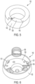
- FIG. 5 illustrates a perspective view of the example inner lock ring 132 of the knob assembly 101.
- the inner lock ring 132 may be a hollow ring forming a center opening.
- the ring 132 may form a ring chamfered region 137.
- the ring chamfered region 137 defines a sloped incline portion 138 extending to a ring opening 142.
- the ring opening 142 is configured to receive the projection flap 108 of the knob 102 when the knob 102 is rotated.
- the sloped incline portion 138 extends from the ring opening 142 to a stop 145.
- the stop 145 is configured to abut the projection flap 108 and rotate the inner lock ring in response to rotation of the projection flap 108.
- the incline portion 138 creates a frictional resistance on the projection flap 108 as the flap 108 slides along the incline portion 138.
- the inner lock ring 132 may be received by the cover such that the ring 132 is seated within the center support 120 of the cover 130.
- the cover chamfered region 128 and the ring chamfered region 137, as well as the ring opening 142 and the cover opening 131 align.
- rotation of the knob 102 may cause rotation of the ring 132.
- the ring 132 may move freely within the center support 120.
- the cover 130 maintains a fixed position while the ring 132 freely rotates.
- the cover incline portion 129 may abut the ring incline portion 138, forcing the ring 132 to move downward as the ring 132 rotates through the channel created by the center support 120. This is described in more detail herein.
- the ring 132 may be made of sheet metal, injected metal, plastic, or any other suitable material.
- FIG. 6 illustrates a perspective view of the example spring 136 and bezel 140 of the knob assembly 101.
- the spring 136 may be a torsion spring or coiled spring configured to impart force in an opposite direction in response to compression of the spring 136.
- the bezel 140 similar to the cover 130 and inner lock ring 132, may form a disc-like shape having a base 150 and a lip 152 around the outer periphery.
- the base 150 may have a recessed portion 154 at the center of the base 150.
- the recessed portion 154 is configured to receive the spring 136.
- the recessed portion 154 may form a cylindrical-shaped opening having a diameter similar to that of the spring 136.
- a plurality of notches 156 may extend from the base. Each notch 156 may create a space between the notch 156 and the base and be configured to lock a portion of one of the arcs 113 of the cover 130 into the space. For example, during assembly, the cover 130 may be placed within the bezel 140. The arc openings 117 of the cover 130 may receive the notches 156. Once seated in the bezel 140, the cover 130 may be rotated so that the notches 156 slide over the arcs 113, thus locking the cover 130 within the bezel 140. This aids in maintaining the cover 130 in a fixed position when the ring 132 is rotated.
- FIG. 7 illustrates a top view of the example knob assembly 101 for a knob 102 of the cooktop of FIG. 1 , where the knob 102 is in a resting position.
- the knob 102 may be the first position with the interface 122 aligned along an axis indicating that the gas release is OFF.
- the knob 102 may be seated within the bezel 140 such that the lip 152 of the bezel 140 surrounds the outer periphery 107 of the knob 102.
- the bezel 140 may receive the cover 130 such that the edges 115 of the arcs 113 of the cover 130 abut an inside surface of the lip 152 of the bezel 140.
- the edges 115 may also engage the outer periphery 107 of the knob.
- the knob 102 may be seated on the cover 130 and within the bezel 140.
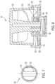
- FIG. 8 illustrates a cross sectional view of the knob assembly of FIG 7 .
- the knob 102 may be seated within the bezel 140 such that the lip 152 of the bezel 140 surrounds the outer periphery 107 of the knob 102.
- the bezel 140 may receive the cover 130 such that the edges 115 of the arcs 113 of the cover 130 abut an inside surface of the lip 152 of the bezel 140.
- the inner lock ring 132 is received within the center support 120 of the cover 130.
- the inner lock ring 132 may form a circular indentation 144 at its underside and be configured to receive at least a portion of the spring 136. This indentation may maintain the spring 136 within the ring 132 and allow the force to be applied to the ring 132, forcing the ring 132 upward against the cover 130.
- the cover 130 may secure the spring 136 within the recessed portion 154 of the bezel 140 by closing off the recessed portion 154.
- the spring 136 may engage with the underside of the inner lock ring 132 and provide the bias force. This force may be translated through the cover 130 and ring 132 and onto the knob 102, forcing the knob in the first, or elevated position.
- the projection flap 108 is not visible in FIG. 10 , but is understood to be arranged above the cover 130 in the resting position.
- the spring 136 will impart the bias force F to return the knob back to the normal elevated position. Gas will not be released, and the bias may ensure that any depression and rotation of the knob are deliberate and release of gas is in response to actuations are not accidental.
- FIG. 9 illustrates a top view of the example knob assembly 101 for a knob 102 of the cooktop of FIG. 1 , where the knob 102 is in an intermediate position. Similar to FIG. 7 , the knob 102 may be seated within the bezel 140 such that the lip 152 of the bezel 140 surrounds the outer periphery 107 of the knob 102. Further, the bezel 140 may receive the cover 130 such that the edges 115 of the arcs 113 of the cover 130 abut an inside surface of the lip 152 of the bezel 140. The edges 115may also engage the outer periphery 107 of the knob. In the intermediate position, the interface 122 of the knob 102 may be aligned perpendicular to the axis.
- the knob 102 may be rotated 90 degrees to this position, though more or fewer degrees of rotation may be appreciated. In this position, the gas may initiate release and the user may hear a clicking sound indicating that the gas release is initiated. In order for this to occur, the user may both press down on the knob 102, as well as rotate the knob 102.
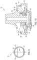
- FIG. 10 illustrates a cross sectional view of the knob assembly of FIG 9 .
- the knob 102 is pressed further into the bezel 140.
- the spring 136 provides resistance to this force and ensures that the depression of the knob 102 was deliberate by the user.
- the knob 102 may be seated within the bezel 140 such that the lip 152 of the bezel 140 surrounds the outer periphery 107 of the knob 102.
- the bezel 140 may receive the cover 130 such that the edges 115 of the arcs 113 of the cover 130 abut an inside surface of the lip 152 of the bezel 140.
- the inner lock ring 132 is received within the center support 120 of the cover 130.
- the knob 102 When the knob 102 is pressed, the knob 102 may move vertically lower within the bezel 140 and the support cylinder 105 moves within central bore 123 of the cover 130. Accordingly, the projection flap 108 may also move vertically lower with respect to the cover 130. By moving the knob 102, and subsequently the projection flap 108 downward, the projection flap 108 may be subsequently aligned with the cover opening 131 at the chamfered region 128 of the cover 130. As explained above, the chamfered region 137 of the inner lock ring 132 is seated inside the chamfered region 128 of the cover 130. The ring opening 142 aligns with the cover opening 131 to allow the projection flap 108 to be received therein.
- the sloped incline 129 of the cover 130 aligns with the sloped incline portion 138 of the ring 132.
- the projection flap 108 is moved downward such that the projection is received within the cover opening 131 and the ring opening 142. Should the knob 102 be released at this point, the spring 136 would bias the knob 102 upwards and return the knob 102 to the resting position.
- the projection flap 108 also rotates into the chamfered region 137 of the ring 132.
- the sloped incline portion 138 of the chamfered region 137 forces the projection to gradually descend further, guiding the projection flap 108 through the ring as the knob 102 continues to rotate.
- the friction created between the projection flap 108 and the ring incline portion 138 is increased by the bias force created by the spring 136.
- the spring 136 is forcing the projection flap 108 upwards, while the rotation of the knob 102 is forcing the projection to slide down the incline portion 138 and into the ring 132.
- This friction creates a resistance recognizable at the knob 102 and by the user. This helps to ensure that any rotation of the knob 102 is intentional, and that the user does in fact wish to initiate the release of gas.
- This portion of the rotation is referred to herein as the intermediate position, where the rotational force required to continue to rotate the knob 102 is greater than any other rotational position.
- the projection flap 108 may abut the stop 145 and rotate more freely. This allows the user to rotate the knob 102 to the desired gas release level without the additional resistance created by the chamfered region 137.
- the spring 136 and chamfered region 137 will impart a force to return the knob 102 back to the normal or resting position. If the rotation was done on purpose by a user, the user will continue to fight against the resistance and rotate the knob 102 until the projection flap 108 engages the inner lock ring 132 and the spark starts to produce a sound and gas is flowing to the burner. After rotating past the intermediate position, the knob 102 may move freely to allow the user to select the desired position of the knob 102 for the desired gas flow.
- a controllable knob 102 that prevents inadvertent actuation from releasing gas accidentally.
- the inner lock ring slides along the incline portion of the cover in response of subsequent rotation of the knob, the incline portion imparting a torque resistance, due to spring action, on the inner lock and the knob to prevent against unintentional rotation of the knob.
- the terms "upper,” “lower,” “right,” “left,” “rear,” “front,” “vertical,” “horizontal,” and derivatives thereof shall relate to the device as oriented in FIG. 1 .
- the device may assume various alternative orientations and step sequences, except where expressly specified to the contrary.
- the specific devices and processes illustrated in the attached drawings, and described in the following specification are simply exemplary embodiments of the inventive concepts defined in the appended claims. Hence, specific dimensions and other physical characteristics relating to the embodiments disclosed herein are not to be considered as limiting, unless the claims expressly state otherwise.
- aspects of the present embodiments may be embodied as a system, method or computer program product. Accordingly, aspects of the present disclosure may take the form of an entirely hardware embodiment, an entirely software embodiment (including firmware, resident software, micro-code, etc.) or an embodiment combining software and hardware aspects that may all generally be referred to herein as a "module” or "system.” Furthermore, aspects of the present disclosure may take the form of a computer program product embodied in one or more computer readable medium(s) having computer readable program code embodied thereon.
Landscapes
- Engineering & Computer Science (AREA)
- Chemical & Material Sciences (AREA)
- Combustion & Propulsion (AREA)
- Mechanical Engineering (AREA)
- General Engineering & Computer Science (AREA)
- Physics & Mathematics (AREA)
- General Physics & Mathematics (AREA)
- Automation & Control Theory (AREA)
- Mechanical Control Devices (AREA)
Abstract
A knob assembly (101) for a gas cooktop (100) may include a knob (102) configured to control a flow of gas from a burner (106) of a cooktop (100) starting at a resting position, the knob (102) defining a hollow interior and having a support cylinder (105) extending vertically through the hollow interior, wherein the support cylinder (105) includes a projection flap (108) protruding therefrom, and an inner lock ring (132) arranged at least partially within the hollow interior of the knob (102) and having a chamfered region (137) defining a ring opening (142) adjacent an inclined portion (138), where the ring opening (142) is configured to selectively receive the projection flap (108) in response to depression of the knob (102) and where the projection flap (108) slides along the inclined portion (138) in response to subsequent rotation of the knob (102), the inclined portion (138) imparting frictional resistance on the projection flap (108) to prevent against unintentional rotation of the knob (102).
Description
- Described herein are hinge systems for a knob mechanism for gas cooktops.
- A cooking appliance is used to cook meals and other foodstuffs on a cooktop or within an oven. The cooking appliance typically includes various control switches and electronics to control the heating elements of the cooking appliance.
- A knob assembly for a gas cooktop may include a knob configured to control a flow of gas from a burner of a cooktop starting at a resting position, the knob defining a hollow interior and having a support cylinder extending vertically through the hollow interior, wherein the support cylinder includes a projection flap protruding therefrom, an inner lock ring arranged at least partially within the hollow interior of the knob and having a chamfered region defining a ring opening adjacent an inclined portion, where the opening is configured to selectively receive the projection flap in response to depression of the knob and where the projection flap slides along the inclined portion in response to subsequent rotation of the knob, the inclined portion imparting frictional resistance on the projection flap to prevent against unintentional rotation of the knob.
- In another embodiment, the incline portion imparts a torque resistance, due to spring action, on the inner lock to prevent against unintentional rotation of the knob.
- In one example, the incline portion extends between the ring opening and a stop, the stop configured to abut the projection flap and rotate the inner lock ring in response to rotation of the projection flap.
- In one embodiment, a bezel is configured to receive at least a portion of the ring and at least a portion of the knob, and defining a base surrounded by a lip.
- In another embodiment, the lip is configured to surround an outer periphery of the knob and define a recessed portion.
- In one example, a spring arranged in the recessed portion of the base and configured to impart a bias force against the inner lock ring to maintain the ring in the resting position when the projection flap is not arranged within the ring opening.
- In one embodiment, the spring is configured to increase the reaction between the inclined portion of the inner lock ring and the inclined portion of the cover.
- In another embodiment, a cover having a center support configured to receive the inner lock ring therein, the cover arranged within the bezel and configured to maintain the spring in the recessed portion.
- In one example, the center support includes a cover opening configured to align with the ring opening for receiving the projection flap.
- In one embodiment, the center support has a cover chamfered region having the incline portion.
- In another embodiment, the cover includes a plurality of arcs around an outer perimeter.
- In one example, the plurality of arcs are configured to engage with a notch arranged on the base of the cover to maintain the cover in a fixed position relative to the base so that the inner lock ring rotates in response to the knob rotating while cover maintains a fixed position on the bezel.
- In one embodiment, the projection flap slides along the incline portion in response to subsequent rotation of the knob,
- In another embodiment, the incline portion creates an intermediate position for the knob to prevent against unintentional rotation of the knob as the projection flap slides along the incline portion.
- The embodiments of the present disclosure are pointed out with particularity in the appended claims. However, other features of the various embodiments will become more apparent and will be best understood by referring to the following detailed description in conjunction with the accompanying drawings in which:
-
FIG. 1 illustrates an example cooktop, such as a gas cooktop; -
FIG. 2 illustrates an exploded view of an example knob assembly of the cooktop ofFIG. 1 ; -
FIG. 3 illustrates a perspective view of a knob of the knob assembly; -
FIG. 4 illustrates a perspective view of an example cover of the knob assembly; -
FIG. 5 illustrates a perspective view of an example inner lock ring of the knob assembly; -
FIG. 6 illustrates a perspective view of an example spring and bezel of the knob assembly; -
FIG. 7 illustrates a top view of an example knob assembly for a knob of the cooktop ofFIG. 1 , where the knob is in a resting position; -
FIG. 8 illustrates a cross sectional view of the knob assembly ofFIG 7 ; -
FIG. 9 illustrates a top view of an example knob assembly for a knob of the cooktop ofFIG. 1 , where the knob is in an intermediate position; and -
FIG. 10 illustrates a cross sectional view of the knob assembly ofFIG 9 . - As required, detailed embodiments of the present invention are disclosed herein; however, it is to be understood that the disclosed embodiments are merely exemplary of the invention that may be embodied in various and alternative forms. The figures are not necessarily to scale; some features may be exaggerated or minimized to show details of particular components. Therefore, specific structural and functional details disclosed herein are not to be interpreted as limiting, but merely as a representative basis for teaching one skilled in the art to variously employ the present invention.
- Knobs in gas cooktops and freestanding ranges are often sensitive to actuation and may be accidentally turned on. While not intended, such accidental actuations or rotations may release gas unknowingly. As described in detail herein, an improved system allows for a resistance to be applied to the actuation during the start of the rotation of the knob assembly. This resistance may ensure that any release of gas is in response to actuations that are deliberate and not accidental.
- The system may include a knob assembly including a knob, cover, inner lock ring, spring, and bezel. The knob may include a projection flap configured to engage the inner lock ring when the knob is rotated to an intermediate position. In this position, the projection flap on the knob may engage the inner lock ring and cause the inner lock ring to rotate with the knob. Up until this intermediate position, the spring may bias the knob into a resting position, forcing the knob to return to its normal position. However, once the knob is rotated so that the projection flap engages with a chamfered region of the inner lock ring, the spring bias is released and the knob may rotate freely.
- Thus, if the rotation was accidental, the spring will impart a force to return the knob back to the normal or resting position. If the rotation was done on purpose by a user, the user will continue to fight against the resistance and rotate the knob until the projection flap engages the inner lock ring and the spark starts to produce a sound and gas is flowing to the burner. After rotating past the intermediate position, the knob may move freely to allow the user to select the desired position of the knob for the desired gas flow. This prevents the knob from leaving its initial position and releasing gas without the spark.
-
FIG. 1 illustrates anexample cooktop 100, such as a gas range assembly. Thecooktop 100 may include acooking area 104 having a plurality ofburners 106, each controlled by aknob 102. Each separately controlledburner 106 is dedicated to supplying heat to that area of thecooking area 104. The heat supplied to each separately controlled heating area is controlled such that a command to change the heat supplied to it may not change the amount of heat supplied to any other separately controlledcooking area 104. In the example ofFIG. 1 , thecooktop 100 has four separately controlledcooking areas 104, but more orfewer cooking areas 104 may be included. - One or
more grates 110 may be arranged above thecooking area 104 in order to maintain cookware thereon a predefined distance above theburners 106. Eachgrate 110 may be made of metal, iron, or some other thermally conductive element. Eachburner 106 may be operable to heat to desired cooking temperatures. In an example, eachknob 102 is configured to control the flow of gas to a respective one of theburners 106. Theknobs 102 may be labeled to allow a user to identify whichknob 102 controls which of theburners 106. Theburners 106 are configured to generate controlled flames that may be used to heat cookware arranged on thegrate 110. The magnitude of the flame generated by theburners 106 is proportionate to the amount of gas flowing to theburners 106. A user may adjust the flow of gas to theburners 106 using theknobs 102. As the user rotates each of theknobs 102, a gas control valve (not shown) changes the amount of gas flowing to thecorresponding burner 106. - While the
knobs 102 in the example ofFIG. 1 are illustrated as being arranged on top of thecooking area 104, the knobs may also be arranged on a front surface of a manifold of thecooktop 100. Theknobs 102 may include markings therearound to indicate a certain level of heat being supplied by theburner 106 relative to the rotational position of theknob 102. For example, markings associated with a high, medium, low, simmer settings may be included. Eachknob 102 has aface 112 with agrip 114 extending outwardly from theface 112. It should be appreciated that in other embodiments eachknob 102 may be contemplated, such as theknob 102 being shaped as a cylinder or oval without a grip. -
FIG. 2 illustrates an exploded view of anexample knob assembly 101 of thecooktop 100 ofFIG. 1 . Theknob assembly 101 may include theknob 102,cover 130,inner lock ring 132,spring 136 andbezel 140. -
FIG. 3 illustrates a perspective view of theknob 102 of theknob assembly 101. In the assembled state, theknob 102 may be received by thebezel 140. Thespring 136 may bias the knob at a first position. Theknob 102 may include aninterface 122 configured to engage with the user's fingers to apply pressure to rotate and actuate theknob 102. Theinterface 122 may also indicate a rotational location of theknob 102, thus indicate the flow level of gas such as high, medium, low, etc. When a user applies pressure to theknob 102, theknob 102 may be pushed downward into thebezel 140 and subsequently rotated. - The
knob 102 may define a hollow interior. Asupport cylinder 105 may extend from the underside of theinterface 122 through the inside center of theknob 102. Thecylinder 105 may form a hollow opening having a generally cylindrical shape and a flat side. Thecylinder 105 may be configured to receive a post during assembly of theknob assembly 101 onto thecooktop 100. - A
projection flap 108 may be arranged on the exterior of thecylinder 105 and within the hollow underside of theknob 102. Theprojection flap 108 may form a cuboid, cube, or rectangular prism. Theprojection flap 108 may extend out at one side of the cylinder and be configured to engage with portions of thecover 130 andinner lock ring 132. -
FIG. 4 illustrates a perspective view of theexample cover 130 of theknob assembly 101. Thecover 130 may form a disk-like shape and include a plurality ofouter arcs 113 spaced from one another. When assembled, anedge 115 of eacharc 113 may extend theouter periphery 107 of theknob 102. The spaces between thearcs 113 may fromarc openings 117. Thecover 130 may include acenter support 120 arranged in the center of thecover 130 and define acentral bore 123. Thecenter support 120 may be raised and have a higher profile than thearcs 113. Thecenter support 120 may also have a higher profile, at least in areas, than theinner lock ring 132. This is discussed further herein. - The
cover 130 may form acenter ring 124 between thecenter support 120 and thearcs 113. Thecenter ring 124 connects thecenter support 120 to thearcs 113 and may be recessed compared to thearcs 113 andcenter support 120. Thecenter support 120 defines a cover chamferedregion 128 defining asloped incline 129 and acover opening 131. In the assembled state, thecenter support 120 support receives theinner lock ring 132 and maintains thering 132 therein while allowing the ring to rotate freely within thecenter support 120. -
FIG. 5 illustrates a perspective view of the exampleinner lock ring 132 of theknob assembly 101. Theinner lock ring 132 may be a hollow ring forming a center opening. Thering 132 may form a ring chamferedregion 137. The ring chamferedregion 137 defines a slopedincline portion 138 extending to aring opening 142. Thering opening 142 is configured to receive theprojection flap 108 of theknob 102 when theknob 102 is rotated. The slopedincline portion 138 extends from thering opening 142 to astop 145. Thestop 145 is configured to abut theprojection flap 108 and rotate the inner lock ring in response to rotation of theprojection flap 108. That is, theincline portion 138 creates a frictional resistance on theprojection flap 108 as theflap 108 slides along theincline portion 138. Once theflap 108 has been rotated through this intermediate position, heflap 108 abuts thestop 145. Further rotation of theflap 108 then causes thering 132 to rotate with theknob 102 until a desired gas release is achieved by the user. - During assembly, the
inner lock ring 132 may be received by the cover such that thering 132 is seated within thecenter support 120 of thecover 130. The cover chamferedregion 128 and the ring chamferedregion 137, as well as thering opening 142 and thecover opening 131 align. When the ring chamferedregion 137 receives theprojection flap 108 of theknob 102, rotation of theknob 102 may cause rotation of thering 132. As explained, thering 132 may move freely within thecenter support 120. Thecover 130 maintains a fixed position while thering 132 freely rotates. Thecover incline portion 129 may abut thering incline portion 138, forcing thering 132 to move downward as thering 132 rotates through the channel created by thecenter support 120. This is described in more detail herein. Thering 132 may be made of sheet metal, injected metal, plastic, or any other suitable material. -
FIG. 6 illustrates a perspective view of theexample spring 136 andbezel 140 of theknob assembly 101. Thespring 136 may be a torsion spring or coiled spring configured to impart force in an opposite direction in response to compression of thespring 136. Thebezel 140, similar to thecover 130 andinner lock ring 132, may form a disc-like shape having a base 150 and alip 152 around the outer periphery. The base 150 may have a recessedportion 154 at the center of the base 150. The recessedportion 154 is configured to receive thespring 136. The recessedportion 154 may form a cylindrical-shaped opening having a diameter similar to that of thespring 136. - A plurality of
notches 156 may extend from the base. Eachnotch 156 may create a space between thenotch 156 and the base and be configured to lock a portion of one of thearcs 113 of thecover 130 into the space. For example, during assembly, thecover 130 may be placed within thebezel 140. Thearc openings 117 of thecover 130 may receive thenotches 156. Once seated in thebezel 140, thecover 130 may be rotated so that thenotches 156 slide over thearcs 113, thus locking thecover 130 within thebezel 140. This aids in maintaining thecover 130 in a fixed position when thering 132 is rotated. -
FIG. 7 illustrates a top view of theexample knob assembly 101 for aknob 102 of the cooktop ofFIG. 1 , where theknob 102 is in a resting position. In the resting position, theknob 102 may be the first position with theinterface 122 aligned along an axis indicating that the gas release is OFF. Theknob 102 may be seated within thebezel 140 such that thelip 152 of thebezel 140 surrounds theouter periphery 107 of theknob 102. Further, thebezel 140 may receive thecover 130 such that theedges 115 of thearcs 113 of thecover 130 abut an inside surface of thelip 152 of thebezel 140. Theedges 115 may also engage theouter periphery 107 of the knob. Thus, as evident inFIG. 7 , theknob 102 may be seated on thecover 130 and within thebezel 140. -
FIG. 8 illustrates a cross sectional view of the knob assembly ofFIG 7 . As explained above, theknob 102 may be seated within thebezel 140 such that thelip 152 of thebezel 140 surrounds theouter periphery 107 of theknob 102. Further, thebezel 140 may receive thecover 130 such that theedges 115 of thearcs 113 of thecover 130 abut an inside surface of thelip 152 of thebezel 140. Theinner lock ring 132 is received within thecenter support 120 of thecover 130. Theinner lock ring 132 may form acircular indentation 144 at its underside and be configured to receive at least a portion of thespring 136. This indentation may maintain thespring 136 within thering 132 and allow the force to be applied to thering 132, forcing thering 132 upward against thecover 130. - The
cover 130, once seated within the bezel, may secure thespring 136 within the recessedportion 154 of thebezel 140 by closing off the recessedportion 154. Thespring 136 may engage with the underside of theinner lock ring 132 and provide the bias force. This force may be translated through thecover 130 andring 132 and onto theknob 102, forcing the knob in the first, or elevated position. Theprojection flap 108 is not visible inFIG. 10 , but is understood to be arranged above thecover 130 in the resting position. - In this resting position, should the
knob 102 be turned, bumped, etc., thespring 136 will impart the bias force F to return the knob back to the normal elevated position. Gas will not be released, and the bias may ensure that any depression and rotation of the knob are deliberate and release of gas is in response to actuations are not accidental. -
FIG. 9 illustrates a top view of theexample knob assembly 101 for aknob 102 of the cooktop ofFIG. 1 , where theknob 102 is in an intermediate position. Similar toFIG. 7 , theknob 102 may be seated within thebezel 140 such that thelip 152 of thebezel 140 surrounds theouter periphery 107 of theknob 102. Further, thebezel 140 may receive thecover 130 such that theedges 115 of thearcs 113 of thecover 130 abut an inside surface of thelip 152 of thebezel 140. The edges 115may also engage theouter periphery 107 of the knob. In the intermediate position, theinterface 122 of theknob 102 may be aligned perpendicular to the axis. Theknob 102 may be rotated 90 degrees to this position, though more or fewer degrees of rotation may be appreciated. In this position, the gas may initiate release and the user may hear a clicking sound indicating that the gas release is initiated. In order for this to occur, the user may both press down on theknob 102, as well as rotate theknob 102. -
FIG. 10 illustrates a cross sectional view of the knob assembly ofFIG 9 . In this intermediate position, theknob 102 is pressed further into thebezel 140. Thespring 136 provides resistance to this force and ensures that the depression of theknob 102 was deliberate by the user. Again, similar to the resting position, theknob 102 may be seated within thebezel 140 such that thelip 152 of thebezel 140 surrounds theouter periphery 107 of theknob 102. Further, thebezel 140 may receive thecover 130 such that theedges 115 of thearcs 113 of thecover 130 abut an inside surface of thelip 152 of thebezel 140. Theinner lock ring 132 is received within thecenter support 120 of thecover 130. - When the
knob 102 is pressed, theknob 102 may move vertically lower within thebezel 140 and thesupport cylinder 105 moves withincentral bore 123 of thecover 130. Accordingly, theprojection flap 108 may also move vertically lower with respect to thecover 130. By moving theknob 102, and subsequently theprojection flap 108 downward, theprojection flap 108 may be subsequently aligned with the cover opening 131 at the chamferedregion 128 of thecover 130. As explained above, the chamferedregion 137 of theinner lock ring 132 is seated inside the chamferedregion 128 of thecover 130. Thering opening 142 aligns with the cover opening 131 to allow theprojection flap 108 to be received therein. - Similarly, the sloped
incline 129 of thecover 130 aligns with the slopedincline portion 138 of thering 132. When theknob 102 is first depressed, theprojection flap 108 is moved downward such that the projection is received within thecover opening 131 and thering opening 142. Should theknob 102 be released at this point, thespring 136 would bias theknob 102 upwards and return theknob 102 to the resting position. However, should the user continue to press down on theknob 102, as well as begin to rotate theknob 102, theprojection flap 108 also rotates into the chamferedregion 137 of thering 132. The slopedincline portion 138 of the chamferedregion 137 forces the projection to gradually descend further, guiding theprojection flap 108 through the ring as theknob 102 continues to rotate. - The friction created between the
projection flap 108 and thering incline portion 138 is increased by the bias force created by thespring 136. Thespring 136 is forcing theprojection flap 108 upwards, while the rotation of theknob 102 is forcing the projection to slide down theincline portion 138 and into thering 132. This friction creates a resistance recognizable at theknob 102 and by the user. This helps to ensure that any rotation of theknob 102 is intentional, and that the user does in fact wish to initiate the release of gas. This portion of the rotation is referred to herein as the intermediate position, where the rotational force required to continue to rotate theknob 102 is greater than any other rotational position. - Once the
knob 102 is rotated such that theprojection flap 108 has navigated through the chamferedregion 137, theprojection flap 108 may abut thestop 145 and rotate more freely. This allows the user to rotate theknob 102 to the desired gas release level without the additional resistance created by the chamferedregion 137. - Again, if the rotation of the
knob 102 was accidental, thespring 136 and chamferedregion 137 will impart a force to return theknob 102 back to the normal or resting position. If the rotation was done on purpose by a user, the user will continue to fight against the resistance and rotate theknob 102 until theprojection flap 108 engages theinner lock ring 132 and the spark starts to produce a sound and gas is flowing to the burner. After rotating past the intermediate position, theknob 102 may move freely to allow the user to select the desired position of theknob 102 for the desired gas flow. - Accordingly, a
controllable knob 102 is disclosed that prevents inadvertent actuation from releasing gas accidentally. The inner lock ring slides along the incline portion of the cover in response of subsequent rotation of the knob, the incline portion imparting a torque resistance, due to spring action, on the inner lock and the knob to prevent against unintentional rotation of the knob. - While exemplary embodiments are described above, it is not intended that these embodiments describe all possible forms of the invention. Rather, the words used in the specification are words of description rather than limitation, and it is understood that various changes may be made without departing from the spirit and scope of the invention. Additionally, the features of various implementing embodiments may be combined to form further embodiments of the invention.
- For purposes of description herein the terms "upper," "lower," "right," "left," "rear," "front," "vertical," "horizontal," and derivatives thereof shall relate to the device as oriented in
FIG. 1 . However, it is to be understood that the device may assume various alternative orientations and step sequences, except where expressly specified to the contrary. It is also to be understood that the specific devices and processes illustrated in the attached drawings, and described in the following specification are simply exemplary embodiments of the inventive concepts defined in the appended claims. Hence, specific dimensions and other physical characteristics relating to the embodiments disclosed herein are not to be considered as limiting, unless the claims expressly state otherwise. - The descriptions of the various embodiments have been presented for purposes of illustration, but are not intended to be exhaustive or limited to the embodiments disclosed. Many modifications and variations will be apparent to those of ordinary skill in the art without departing from the scope and spirit of the described embodiments.
- Aspects of the present embodiments may be embodied as a system, method or computer program product. Accordingly, aspects of the present disclosure may take the form of an entirely hardware embodiment, an entirely software embodiment (including firmware, resident software, micro-code, etc.) or an embodiment combining software and hardware aspects that may all generally be referred to herein as a "module" or "system." Furthermore, aspects of the present disclosure may take the form of a computer program product embodied in one or more computer readable medium(s) having computer readable program code embodied thereon.
Claims (14)
- A knob assembly (101) for a gas cooktop (100), comprising:a knob (102) configured to control a flow of gas from a burner (106) of a cooktop (100) starting at a resting position, the knob (102) defining a hollow interior and having a support cylinder (105) extending vertically through the hollow interior, wherein the support cylinder (105) includes a projection flap (108) protruding therefrom; andan inner lock ring (132) arranged at least partially within the hollow interior of the knob (102) and having a chamfered region (137) defining a ring opening (142) adjacent a sloped incline portion (138), where the ring opening (142) is configured to selectively receive the projection flap (108) in response to depression of the knob (102) and where the inner lock ring (132) slides along the incline portion (138) in response of subsequent rotation of the knob (102).
- The assembly (101) of claim 1, wherein the incline portion (138) imparts a torque resistance, due to spring action, on the inner lock ring (132) to prevent against unintentional rotation of the knob (102).
- The assembly (101) of claim 2, wherein the incline portion (138) extends between the ring opening (142) and a stop (145), the stop (145) configured to abut the projection flap (108) and rotate the inner lock ring (132) in response to rotation of the projection flap (108).
- The assembly (101) of claim 1, further comprising a bezel (140) configured to receive at least a portion of the inner lock ring (132) and at least a portion of the knob (102), and defining a base (150) surrounded by a lip (152).
- The assembly (101) of claim 1, wherein the lip (152) is configured to surround an outer periphery of the knob (102) and define a recessed portion (154).
- The assembly (101) of claim 5, further comprising a spring (136) arranged in the recessed portion (154) of the base (150) and configured to impart a bias force against the inner lock ring (132) to maintain the inner lock ring (132) in the resting position when the projection flap (108) is not arranged within the ring opening (142).
- The assembly (101) of any of claims 4 to 6, further comprising a cover (130) having a center support (120) configured to receive the inner lock ring (132) therein, the cover (130) arranged within the bezel (140) and configured to maintain the spring (132) in the recessed portion (154).
- The assembly (101) of claims 6 or 7, wherein the spring is configured to increase the reaction between the inclined portion (138) of the inner lock ring (132) and the inclined portion (138) of the cover (130).
- The assembly (101) of claims 7 or 8, wherein the center support (120) includes a cover opening (131) configured to align with the ring opening (142) for receiving the projection flap (108).
- The assembly (101) of claim 9, wherein the center support (120) includes the chamfered region (137) having the incline portion (138).
- The assembly (101) of any of claims 7 to 10, wherein the cover (130) includes a plurality of arcs (113) around an outer perimeter.
- The assembly (101) of claim 11, wherein the plurality of arcs (113) are configured to engage with a notch (156) arranged on the base (150) of the cover (130) to maintain the cover (130) in a fixed position relative to the base (150) so that the inner lock ring (132) rotates in response to the knob (102) rotating while cover maintains a fixed position on the bezel (140).
- The assembly (101) of any of the preceding claims, wherein the projection flap (108) slides along the incline portion (138) in response to subsequent rotation of the knob (102).
- The assembly (101) of claim 13, where the incline portion (138) creates an intermediate position for the knob (102) to prevent against unintentional rotation of the knob (102) as the projection flap (108) slides along the incline portion (138).
Applications Claiming Priority (1)
| Application Number | Priority Date | Filing Date | Title |
|---|---|---|---|
| US17/681,222 US11788730B2 (en) | 2022-02-25 | 2022-02-25 | Knob mechanism for gas cooktop |
Publications (1)
| Publication Number | Publication Date |
|---|---|
| EP4235034A1 true EP4235034A1 (en) | 2023-08-30 |
Family
ID=85239061
Family Applications (1)
| Application Number | Title | Priority Date | Filing Date |
|---|---|---|---|
| EP23156419.6A Withdrawn EP4235034A1 (en) | 2022-02-25 | 2023-02-13 | Knob mechanism for gas cooktop |
Country Status (2)
| Country | Link |
|---|---|
| US (1) | US11788730B2 (en) |
| EP (1) | EP4235034A1 (en) |
Families Citing this family (5)
| Publication number | Priority date | Publication date | Assignee | Title |
|---|---|---|---|---|
| USD1014443S1 (en) * | 2021-05-04 | 2024-02-13 | Schneider Electric Industries Sas | Part of a circuit breaker |
| US12148583B2 (en) * | 2022-08-01 | 2024-11-19 | Whirlpool Corporation | Removable bezel assembly for a cooking appliance |
| US12050481B1 (en) * | 2023-01-31 | 2024-07-30 | Haier Us Appliance Solutions, Inc. | Systems for knob lockout on appliances |
| KR20250008359A (en) * | 2023-07-07 | 2025-01-14 | 엘지전자 주식회사 | Control unit and cooking appliance including the same |
| WO2025258835A1 (en) * | 2024-06-11 | 2025-12-18 | 엘지전자 주식회사 | Knob assembly and cooking appliance comprising same |
Citations (2)
| Publication number | Priority date | Publication date | Assignee | Title |
|---|---|---|---|---|
| GB1258576A (en) * | 1969-01-19 | 1971-12-30 | ||
| EP3058277B1 (en) * | 2013-10-17 | 2017-12-13 | BSH Hausgeräte GmbH | Actuator for a gas valve, gas valve, and range |
Family Cites Families (6)
| Publication number | Priority date | Publication date | Assignee | Title |
|---|---|---|---|---|
| US2829538A (en) | 1953-02-06 | 1958-04-08 | Ervin H Mueller | Safety adapter for operating handles of valves |
| US4300525A (en) | 1979-06-15 | 1981-11-17 | Jesus Delgado | Safe knob |
| IT1215391B (en) | 1987-03-20 | 1990-02-08 | Smeg Spa | SAFETY DEVICE AGAINST THE ACCIDENTAL OPENING OF TAPS OR SWITCHES IN THE KITCHEN OR GAS OR ELECTRIC HOB. |
| US5165654A (en) * | 1991-09-11 | 1992-11-24 | Liu Hsing Fu | Gas control valve |
| US9074770B2 (en) | 2011-12-15 | 2015-07-07 | Honeywell International Inc. | Gas valve with electronic valve proving system |
| US8899264B2 (en) | 2011-12-15 | 2014-12-02 | Honeywell International Inc. | Gas valve with electronic proof of closure system |
-
2022
- 2022-02-25 US US17/681,222 patent/US11788730B2/en active Active
-
2023
- 2023-02-13 EP EP23156419.6A patent/EP4235034A1/en not_active Withdrawn
Patent Citations (2)
| Publication number | Priority date | Publication date | Assignee | Title |
|---|---|---|---|---|
| GB1258576A (en) * | 1969-01-19 | 1971-12-30 | ||
| EP3058277B1 (en) * | 2013-10-17 | 2017-12-13 | BSH Hausgeräte GmbH | Actuator for a gas valve, gas valve, and range |
Also Published As
| Publication number | Publication date |
|---|---|
| US20230272915A1 (en) | 2023-08-31 |
| US11788730B2 (en) | 2023-10-17 |
Similar Documents
| Publication | Publication Date | Title |
|---|---|---|
| US11788730B2 (en) | Knob mechanism for gas cooktop | |
| EP3492815B1 (en) | Cooking device | |
| US12228291B2 (en) | Cooking appliance with self-closing user control | |
| CN113905641B (en) | Oven with haptic feedback control | |
| US11486574B2 (en) | Gas cooking appliance with ignition position indicator | |
| KR20080073292A (en) | Gas cook-top with glass (capacitive) touch control and automatic burner re-ignition | |
| US20250370494A1 (en) | Knob mechanism for gas cooktop | |
| US20220178547A1 (en) | Gas cooking appliance with active igniter indicator | |
| US10082295B2 (en) | Gas heating arrangement and method for operating a gas heating arrangement | |
| EP3879181A1 (en) | Knob assembly for a cooking appliance and method of assembling | |
| KR102627660B1 (en) | Knob and cooking appliance having the same | |
| US6375150B1 (en) | Knob for gas apparatus with safety button | |
| KR102133284B1 (en) | Cooking device | |
| JP2017009242A (en) | Gas cooking stove | |
| US12366362B2 (en) | Knob mechanism for gas cooktop | |
| US20180045418A1 (en) | Gas cooktop with defined simmer settings | |
| JP2016156593A (en) | Gas stove | |
| JP6271455B2 (en) | Thermal power control device | |
| CN218094373U (en) | Plug valves and gas appliances | |
| KR200253012Y1 (en) | The non-rotating structure of knob ring which is fixed in gas oven range | |
| US20260043547A1 (en) | Cooking appliance with stepper motor activated gas valves | |
| CN218094372U (en) | Plug valve and gas equipment | |
| US20220253088A1 (en) | Cooking appliance and knob assembly for preventing accidental engagement | |
| JP6588808B2 (en) | Cooker | |
| EP3847397B1 (en) | A gas cooker comprising a knob |
Legal Events
| Date | Code | Title | Description |
|---|---|---|---|
| PUAI | Public reference made under article 153(3) epc to a published international application that has entered the european phase |
Free format text: ORIGINAL CODE: 0009012 |
|
| STAA | Information on the status of an ep patent application or granted ep patent |
Free format text: STATUS: THE APPLICATION HAS BEEN PUBLISHED |
|
| AK | Designated contracting states |
Kind code of ref document: A1 Designated state(s): AL AT BE BG CH CY CZ DE DK EE ES FI FR GB GR HR HU IE IS IT LI LT LU LV MC ME MK MT NL NO PL PT RO RS SE SI SK SM TR |
|
| STAA | Information on the status of an ep patent application or granted ep patent |
Free format text: STATUS: THE APPLICATION IS DEEMED TO BE WITHDRAWN |
|
| 18D | Application deemed to be withdrawn |
Effective date: 20240301 |