EP4235031A1 - Injector, combustor comprising same, and gas turbine comprising same - Google Patents
Injector, combustor comprising same, and gas turbine comprising same Download PDFInfo
- Publication number
- EP4235031A1 EP4235031A1 EP22878728.9A EP22878728A EP4235031A1 EP 4235031 A1 EP4235031 A1 EP 4235031A1 EP 22878728 A EP22878728 A EP 22878728A EP 4235031 A1 EP4235031 A1 EP 4235031A1
- Authority
- EP
- European Patent Office
- Prior art keywords
- slits
- injector
- slit
- along
- reference circle
- Prior art date
- Legal status (The legal status is an assumption and is not a legal conclusion. Google has not performed a legal analysis and makes no representation as to the accuracy of the status listed.)
- Granted
Links
Images








Classifications
-
- F—MECHANICAL ENGINEERING; LIGHTING; HEATING; WEAPONS; BLASTING
- F23—COMBUSTION APPARATUS; COMBUSTION PROCESSES
- F23R—GENERATING COMBUSTION PRODUCTS OF HIGH PRESSURE OR HIGH VELOCITY, e.g. GAS-TURBINE COMBUSTION CHAMBERS
- F23R3/00—Continuous combustion chambers using liquid or gaseous fuel
- F23R3/28—Continuous combustion chambers using liquid or gaseous fuel characterised by the fuel supply
- F23R3/286—Continuous combustion chambers using liquid or gaseous fuel characterised by the fuel supply having fuel-air premixing devices
-
- B—PERFORMING OPERATIONS; TRANSPORTING
- B05—SPRAYING OR ATOMISING IN GENERAL; APPLYING FLUENT MATERIALS TO SURFACES, IN GENERAL
- B05B—SPRAYING APPARATUS; ATOMISING APPARATUS; NOZZLES
- B05B1/00—Nozzles, spray heads or other outlets, with or without auxiliary devices such as valves, heating means
- B05B1/02—Nozzles, spray heads or other outlets, with or without auxiliary devices such as valves, heating means designed to produce a jet, spray, or other discharge of particular shape or nature, e.g. in single drops, or having an outlet of particular shape
- B05B1/04—Nozzles, spray heads or other outlets, with or without auxiliary devices such as valves, heating means designed to produce a jet, spray, or other discharge of particular shape or nature, e.g. in single drops, or having an outlet of particular shape in flat form, e.g. fan-like, sheet-like
- B05B1/044—Slits, e.g. narrow openings defined by two straight and parallel lips; Elongated outlets for producing very wide discharges, e.g. fluid curtains
-
- B—PERFORMING OPERATIONS; TRANSPORTING
- B05—SPRAYING OR ATOMISING IN GENERAL; APPLYING FLUENT MATERIALS TO SURFACES, IN GENERAL
- B05B—SPRAYING APPARATUS; ATOMISING APPARATUS; NOZZLES
- B05B1/00—Nozzles, spray heads or other outlets, with or without auxiliary devices such as valves, heating means
- B05B1/14—Nozzles, spray heads or other outlets, with or without auxiliary devices such as valves, heating means with multiple outlet openings; with strainers in or outside the outlet opening
- B05B1/18—Roses; Shower heads
-
- B—PERFORMING OPERATIONS; TRANSPORTING
- B05—SPRAYING OR ATOMISING IN GENERAL; APPLYING FLUENT MATERIALS TO SURFACES, IN GENERAL
- B05B—SPRAYING APPARATUS; ATOMISING APPARATUS; NOZZLES
- B05B1/00—Nozzles, spray heads or other outlets, with or without auxiliary devices such as valves, heating means
- B05B1/14—Nozzles, spray heads or other outlets, with or without auxiliary devices such as valves, heating means with multiple outlet openings; with strainers in or outside the outlet opening
- B05B1/18—Roses; Shower heads
- B05B1/182—Roses; Shower heads characterised by their outlet openings or elements; Mounting arrangements therefor
- B05B1/1821—Roses; Shower heads characterised by their outlet openings or elements; Mounting arrangements therefor the outlet openings arranged in plural groups or rows
- B05B1/1823—Concentric or coaxial groups
-
- B—PERFORMING OPERATIONS; TRANSPORTING
- B05—SPRAYING OR ATOMISING IN GENERAL; APPLYING FLUENT MATERIALS TO SURFACES, IN GENERAL
- B05B—SPRAYING APPARATUS; ATOMISING APPARATUS; NOZZLES
- B05B1/00—Nozzles, spray heads or other outlets, with or without auxiliary devices such as valves, heating means
- B05B1/34—Nozzles, spray heads or other outlets, with or without auxiliary devices such as valves, heating means designed to influence the nature of flow of the liquid or other fluent material, e.g. to produce swirl
- B05B1/3405—Nozzles, spray heads or other outlets, with or without auxiliary devices such as valves, heating means designed to influence the nature of flow of the liquid or other fluent material, e.g. to produce swirl to produce swirl
- B05B1/341—Nozzles, spray heads or other outlets, with or without auxiliary devices such as valves, heating means designed to influence the nature of flow of the liquid or other fluent material, e.g. to produce swirl to produce swirl before discharging the liquid or other fluent material, e.g. in a swirl chamber upstream the spray outlet
- B05B1/3489—Nozzles having concentric outlets
-
- F—MECHANICAL ENGINEERING; LIGHTING; HEATING; WEAPONS; BLASTING
- F02—COMBUSTION ENGINES; HOT-GAS OR COMBUSTION-PRODUCT ENGINE PLANTS
- F02K—JET-PROPULSION PLANTS
- F02K9/00—Rocket-engine plants, i.e. plants carrying both fuel and oxidant therefor; Control thereof
- F02K9/42—Rocket-engine plants, i.e. plants carrying both fuel and oxidant therefor; Control thereof using liquid or gaseous propellants
- F02K9/44—Feeding propellants
- F02K9/52—Injectors
-
- F—MECHANICAL ENGINEERING; LIGHTING; HEATING; WEAPONS; BLASTING
- F23—COMBUSTION APPARATUS; COMBUSTION PROCESSES
- F23R—GENERATING COMBUSTION PRODUCTS OF HIGH PRESSURE OR HIGH VELOCITY, e.g. GAS-TURBINE COMBUSTION CHAMBERS
- F23R3/00—Continuous combustion chambers using liquid or gaseous fuel
- F23R3/02—Continuous combustion chambers using liquid or gaseous fuel characterised by the air-flow or gas-flow configuration
- F23R3/16—Continuous combustion chambers using liquid or gaseous fuel characterised by the air-flow or gas-flow configuration with devices inside the flame tube or the combustion chamber to influence the air or gas flow
-
- F—MECHANICAL ENGINEERING; LIGHTING; HEATING; WEAPONS; BLASTING
- F23—COMBUSTION APPARATUS; COMBUSTION PROCESSES
- F23R—GENERATING COMBUSTION PRODUCTS OF HIGH PRESSURE OR HIGH VELOCITY, e.g. GAS-TURBINE COMBUSTION CHAMBERS
- F23R3/00—Continuous combustion chambers using liquid or gaseous fuel
- F23R3/02—Continuous combustion chambers using liquid or gaseous fuel characterised by the air-flow or gas-flow configuration
- F23R3/16—Continuous combustion chambers using liquid or gaseous fuel characterised by the air-flow or gas-flow configuration with devices inside the flame tube or the combustion chamber to influence the air or gas flow
- F23R3/18—Flame stabilising means, e.g. flame holders for after-burners of jet-propulsion plants
- F23R3/20—Flame stabilising means, e.g. flame holders for after-burners of jet-propulsion plants incorporating fuel injection means
-
- F—MECHANICAL ENGINEERING; LIGHTING; HEATING; WEAPONS; BLASTING
- F23—COMBUSTION APPARATUS; COMBUSTION PROCESSES
- F23R—GENERATING COMBUSTION PRODUCTS OF HIGH PRESSURE OR HIGH VELOCITY, e.g. GAS-TURBINE COMBUSTION CHAMBERS
- F23R3/00—Continuous combustion chambers using liquid or gaseous fuel
- F23R3/28—Continuous combustion chambers using liquid or gaseous fuel characterised by the fuel supply
- F23R3/283—Attaching or cooling of fuel injecting means including supports for fuel injectors, stems, or lances
-
- F—MECHANICAL ENGINEERING; LIGHTING; HEATING; WEAPONS; BLASTING
- F23—COMBUSTION APPARATUS; COMBUSTION PROCESSES
- F23R—GENERATING COMBUSTION PRODUCTS OF HIGH PRESSURE OR HIGH VELOCITY, e.g. GAS-TURBINE COMBUSTION CHAMBERS
- F23R2900/00—Special features of, or arrangements for continuous combustion chambers; Combustion processes therefor
- F23R2900/00002—Gas turbine combustors adapted for fuels having low heating value [LHV]
-
- F—MECHANICAL ENGINEERING; LIGHTING; HEATING; WEAPONS; BLASTING
- F23—COMBUSTION APPARATUS; COMBUSTION PROCESSES
- F23R—GENERATING COMBUSTION PRODUCTS OF HIGH PRESSURE OR HIGH VELOCITY, e.g. GAS-TURBINE COMBUSTION CHAMBERS
- F23R2900/00—Special features of, or arrangements for continuous combustion chambers; Combustion processes therefor
- F23R2900/00014—Reducing thermo-acoustic vibrations by passive means, e.g. by Helmholtz resonators
Definitions
- the present disclosure relates to an injector, a burner including the same, and a gas turbine including the same.
- the gas turbine manufacturers have determined hydrogen (H 2 ) that does not include carbon and thus does not generate carbon dioxide during combustion as a new measure, and thus have developed technologies using hydrogen from the early 2000-th.
- hydrogen shows a high reactive property, and shows a flame propagation speed of about 6 times as high as those of existing fuels, such as methane, propane (C 3 H 8 ) and ethylene (C 2 H 4 ). Accordingly, hydrogen may have a wide operation range without a swirl generator but may tend to cause flashbacks as well.
- the flashback means that a propagation speed of flames becomes higher than the flow velocity of supplied reactant mixture due to a high reactive property or strong combustion oscillations of hydrogen flame and thus the flames flow back. Because the flames that flowed back to an upstream side are attached to a site, at which a design for cooling is vulnerable and fuse a system, it is impossible to stably drive a hydrogen gas turbine in an existing burner nozzle structure that has utilized natural gas as a main fuel.
- FIG. 1 is a view conceptually illustrating a cross-section of a conventional multi-tube injector.
- An aspect of the present disclosure provides an injector that may alleviate flashbacks of hydrogen flames, a burner including the same, and a gas turbine including the same.
- Another aspect of the present disclosure provides an injector that may alleviate combustion oscillations, a burner including the same, and a gas turbine including the same.
- An injector may include an injector body, and a slit formed to pass the injector body along a reference direction, and the slit may include a first slit portion having a shape that extends along a circumferential direction of an imaginary reference circle, a center of which is an imaginary reference axis that extends along the reference direction, and a second slit portion having a shape that extends along a radial direction of the reference circle.
- the first slit portion may include a (1-1)-th slit having a shape that extends along an imaginary first reference circle, a center of which is the reference axis, and a (1-2)-th slit having a shape that extends along a circumferential direction of an imaginary second reference circle, a center of which is the reference axis and a diameter of which is larger than that of the first reference circle.
- the second slit portion may include a (2-1)-th slit disposed in the first area and extending in a radial direction of the first reference circle.
- the (1-1)-th slit and the (2-1)-th slit when viewed along the reference direction, may be spaced apart from each other along the radial direction of the first reference circle.
- a plurality of (1-1)-th slits may be formed, and wherein the plurality of (1-1)-th slits may be spaced apart from each other along a circumferential direction of the first reference circle, and a portion of the first reference circle may have a shape of a first reference arc.
- a plurality of (1-2)-th slits may be formed, the plurality of (1-2)-th slits may be spaced apart from each other along a circumferential direction of the second reference circle, and a portion of the second reference circle may have a shape of a second reference arc, and a size of a central angle of a first fan shape that defines the first reference arc may be larger than a size of a second fan shape that defines the second reference arc.
- a plurality of (2-1)-th slits may be formed, and the plurality of (2-1)-th slits may be spaced apart from each other along the circumferential direction of the first reference circle.
- a plurality of (1-1)-th slits may be formed, the plurality of (1-1)-th slits may be spaced apart from each other along the circumferential direction of the first reference circle, and when it is assumed that a space between a pair of (1-1)-th slits that are adjacent to each other is a (1-1)-th spacing space, the (2-1)-th slit may include a spacing space overlapping slit that overlaps the (1-1)-th spacing space when viewed along the radial direction.
- a plurality of (1-1)-th slits and a plurality of (1-2)-th slots may be formed, and the number of the (1-1)-th slits may be smaller than the number of the (1-2)-th slits.
- the first slit portion may further include a (1-3)-th slit having a shape that extends along a circumferential direction of an imaginary third reference circle, a center of which is the reference axis and a diameter of which is larger than that of the second reference circle, and when it is assumed that an area between the second reference circle and the third reference circle is a second area, the second slit portion may further include a (2-2)-th slit disposed in the second area and extending in a radial direction of the second reference circle.
- a plurality of (2-1)-th slits and a plurality of (2-2)-th slots may be formed, and the number of the (2-1)-th slits may be smaller than the number of the (2-2)-th slits.
- a plurality of (2-1)-th slits and a plurality of (2-2)-th slots may be formed, and the (2-2)-th slit may include an overlapping slit that overlaps any one of the (2-1)-th slits when viewed along the radial direction.
- a plurality of (2-1)-th slits and a plurality of (2-2)-th slots may be formed, and when it is assumed that one direction that is perpendicular to the reference direction is a first direction and one direction that is perpendicular to the reference direction and the first direction is a second direction, the number of the (2-1)-th slits located in a first reference area defined by a first line extending from the reference axis along the first direction and a second line extending from the reference axis along the second direction, when viewed along the reference direction, may be the same as the number of the (2-2)-th slits located in the first reference area and the number of the (2-1)-th slits located in a second reference area defined by the first line and a third line extending from the reference axis along an opposite direction to the second direction may be smaller than the number of the (2-2)-th slits located in the second reference area.
- the numbers of the (2-1)-th slits and the (2-2)-th slits located in the first reference area may be the same as the numbers of the (2-1)-th slits and the (2-2)-th slits located in a third reference area defined by a fourth line extending from the reference axis along an opposite direction to the first direction and the third line
- the numbers of the (2-1)-th slits and the (2-2)-th slits located in the second reference area may be the same as the numbers of the (2-1)-th slits and the (2-2)-th slits located in a fourth reference area defined by the second line and the fourth line, respectively.
- the plurality of second slit portions may be provided, and the numbers of the second slit portions disposed on opposite sides of a reference plane that is an imaginary plane including the reference axis when the injector body is divided by the reference plane may be different.
- a burner may include a supply pipe that supplies a fuel and air, an injector coupled to the supply pipe and that injects the fuel and the air, which are introduced thereinto, and a combustion chamber configured such that the fuel and the air injected by the injector are introduced thereinto, the injector may include a slit extending along a reference direction, and the slit may include a first slit portion having a shape that extends along a circumference direction of an imaginary reference circle, and a second slit portion having a shape that extends along a radial direction of the reference circle.
- a gas turbine may include a compressor that compresses and discharge air, a burner that mixes a fuel and the air compressed and discharged by the compressor, and then generate a combustion gas by burning a mixture of the fuel and the air, and turbine blades that is rotated by the combustion gas delivered from the burner, the burner may include an injector that injects the fuel and the air compressed and discharged by the compressor, which are mixed, and the injector may include a slit including a first slit portion having a shape that extends along a circumferential direction of the imaginary reference circle and a second slit portion having a shape that extends along a radial direction of the reference circle.
- a flashback phenomenon may be alleviated.
- the slits having widths that are similar to the thicknesses of the flames are included as compared with the conventional multi-tube circular injector to restrain a change of the surfaces of the flames, the instability of combustion may be alleviated and combustion oscillations may be alleviated.
- An injector according to the present disclosure may be an injector that is applied to a burner of a gas turbine.
- FIG. 2 is a cutaway perspective view conceptually illustrating a gas turbine, to which an injector according to the present disclosure may be applied.
- FIG. 3 is a view conceptually illustrating a cross-section of a burner, to which an injector according to the present disclosure may be applied.
- FIG. 3 may be understood as a conceptual illustration of area "B" of FIG. 2 .
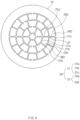
- FIG. 4 is a view conceptually illustrating an appearance of an injector according to a first embodiment of the present disclosure, when viewed from a reference direction.
- FIG. 5 is a view conceptually illustrating the injector according to a first embodiment of the present disclosure.
- FIG. 6 is a view conceptually illustrating a cross-section of any one of slits of the injector according to a first embodiment of the present disclosure.
- the injector may include an injector body 10 and slits 20.
- the slits 20 may be formed to pass through the injector body 10 along a reference direction "D".
- the injector body 10 may be formed of a metallic material.
- the injector body 10 may extend along the reference direction "D".
- the slits 20 may include first slit portions 21 and second slit portions 22.
- the first slit portions 21 may have shapes that extend along a circumferential direction of an imaginary reference circle.
- the reference circle may be a circle, a center of which is an imaginary reference axis that extends along the reference direction "D".
- a first width of the first slit portions 21 may be 0.37 mm to 2 mm. Preferably, the first width may be 1.5 mm.
- the first width may be a length of the first slit portions 21 along a direction that is perpendicular to an extension direction of the first slit portions 21.
- the first width may be similar to a thickness which hydrogen frames may theoretically have.
- the second slit portions 22 may have shapes that extend along a radial direction of the reference circle.
- a second width of the second slit portions 22 may be 0.37 mm to 2 mm.
- the second width may be 1.5 mm.
- the second width may be a length of the second slit portions 22 along a direction that is perpendicular to an extension direction of the second slit portions 22.
- the second width may be similar to a thickness which hydrogen frames may theoretically have.
- the first slit portions 21 may include a (1-1)-th slit 21a and a (1-2)-th slit 21b.
- the (1-1)-th slit 21a may have a shape that extends along an imaginary first reference circle, a center of which is the reference axis.
- the (1-2)-th slit 21b may have a shape that extends along an imaginary second reference circle, a center of which is the reference axis.
- a diameter of the second reference circle may be larger than that of the first reference circle.
- a plurality of slits 21a may be formed.
- the plurality of (1-1)-th slits 21a may be spaced apart from each other along a circumferential direction of the first reference circle, and may have shapes of a first reference arc that is a portion of the first reference circle.
- a (1-1)-th spacing space S1 may be formed between a pair of (1-1)-th slits 21a that are adjacent to each other.
- a plurality of slits 21b may be formed.
- the plurality of (1-2)-th slits 21b may be spaced apart from each other along a circumferential direction of the second reference circle, and may have shapes of a second reference arc that is a portion of the second reference circle.
- a size of a central angle of a first fan shape that defines the first reference arc may be larger than a size of a central angle of a second fan shape that defines the second reference arc. This mean that the number of the (1-1)-th slits 21a is smaller than the number of the (1-2)-th slits 21b.
- the slit portions 22 may include (2-1)-th slits 22a.
- the (2-1)-th slits 22a may be disposed in a first area AR1, and may extend in a radial direction of the first reference circle.
- the first area AR1 may mean an area between the first reference circle and the second reference circle.
- a plurality of slits 22a may be formed.
- the plurality of (2-1)-th slits 22a may be spaced apart from each other along a circumferential direction of the first reference circle.
- the (2-1)-th slits 22a may include spacing space overlapping slits 22a'.
- the spacing space overlapping slits 22a' may mean the (2-1)-th slits that overlap the (1-1)-th spacing space S1 when viewed along radial directions of the plurality of (2-1)-th slits 22a.
- This may mean that the plurality of (2-1)-th slits 22a may include (2-1)-th slits that overlap the (1-1)-th spacing space S1 and (2-1)-th slits that do not overlap it, when viewed along the radial directions.
- the first slit portions 21 may further include (1-3)-th slits 21c.
- the (1-3)-th slit 21c may have shapes that extend along a circumferential direction of a third reference circle.
- the third reference circle may be an imaginary circle, a center of which is the reference axis and a diameter of which is larger than that of the second reference circle.
- a plurality of (1-3)-th slits 21c may be formed.
- the plurality of (1-3)-th slits 21c may be spaced apart from each other along the circumferential direction of the third reference circle, and may have shapes of a third reference arc that is a portion of the third reference circle.
- the slit portions 22 may further include the (2-2)-th slits 22b.
- the (2-2)-th slits 22b may be disposed in a second area AR2, and may extend in a radial direction of the second reference circle.
- the second area AR2 may mean an area between the second reference circle and the third reference circle.
- a plurality of (2-2)-th slits 22b may be formed.
- the plurality of (2-2)-th slits 22b may be spaced apart from each other along a circumferential direction of the second reference circle.
- the (2-2)-th slits 22b may include overlapping slits 22b'.
- the overlapping slits 22b' may mean the (2-2)-th slits that overlap any one of the (2-1)-th slits 22a' when viewed along radial directions of the (2-2)-th slits 22b.
- the plurality of (2-2)-th slits 22b may include (2-2)-th slits that overlap any one of the (2-1)-th slits 22a, and (2-2)-th slits that do not overlap it.
- the injector according to the first embodiment of the present disclosure may be an injector, in which a flashback phenomenon may be alleviated.
- FIG. 6 is a view conceptually illustrating a cross-section of any one of slits of the injector according to a first embodiment of the present disclosure.
- a premixed fuel/air mixture may be supplied to the slits 20 along the reference direction "D".
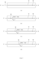
- FIG. 7 is a view conceptually illustrating a flashback phenomenon.
- flames 30 that undergo flashback may flow in an opposite direction D' to the reference direction "D".
- the injector according to the first embodiment of the present disclosure includes the slits 20, cross-sectional areas of which are larger than those of a conventional multi-tube nozzle with reference to volumes thereof.
- the slits 20 having the larger cross-sectional area with reference to volumes may decrease a flashback phenomenon as compared with the conventional multi-tube nozzle due to two following reasons.
- the flames that undergo flashback may induce heat loss through the metallic injector body 10 while they pass through the slits 20.
- the heat loss becomes higher than the heat generated by the combustion reaction, the combustion reaction may be suppressed.
- the present disclosure includes the slits 20 having the larger cross-sectional area than that of the multi-tube nozzle with reference to volumes, an area, in which the flames that flow back may contact an inner surface of the injector body 10, may be increased. Accordingly, heat loss may be increased as compared with the conventional multi-tube nozzle, which may decrease the flashback phenomenon.
- radical ions are repeatedly generated and re-bonded.
- hydrogen radicals are diffused via a wall surface of the metallic injector body 10, and the diffusion of the hydrogen radicals on the wall surface may suppress the combustion reaction.
- the hydrogen radicals are intermediate products that are necessary for a combustion reaction mechanism, and the combustion reaction may be halted when the hydrogen radicals disappear due to the diffusion on the wall surface.
- the present disclosure includes the slits 20 having a larger cross-sectional area than that of the conventional multi-tube nozzle with reference to volumes, an area, in which the hydrogen radicals may disappear due to the diffusion on the wall surface, may be provided, and thus the flashback phenomenon may be alleviated.
- the injector according to the first embodiment of the present disclosure may be an injector, in which combustion oscillations may be alleviated.
- the combustion oscillations are related to combustion instability. Because the combustion instability is dominantly influenced by a change in the shape of the flames, the change in the shape of the flames has to be minimized for the control. To minimize the change in the shape of the flames, the shape of the flames has to have a shape having a relatively large surface area.
- the conical flames may be contracted and expanded due to external perturbations. Accordingly, a possibility of, the shapes of the flames, being changed may be high.
- the injector according to the first embodiment of the present disclosure includes the slits having a larger cross-sectional area with reference to volumes, a possibility of the change in the thin flame surface is relatively low, and thus, a heat release rate of the flames may become lower and an instability of combustion may be decreased, whereby combustion vibrations may be restrained.
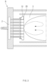
- FIG. 8 is a view conceptually illustrating equipment for a hydrogen combustion test.
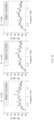
- FIG. 9 is a view illustrating a comparison result of hydrogen combustion tests of the multi-tube injector of FIG. 1 and the injector of FIG. 4 .
- the equipment for a hydrogen combustion test may include a fuel/air mixing part 100, a quartz tube 200, a metal tube 300, and a dynamic pressure sensor 400.
- the metal tube 300 may include a cooling air introducing pipe 310 and a piston 320.
- the injector body 10 may be disposed between the fuel/air mixing part 100 and the quartz tube 200.
- the dynamic pressure sensor 400 may be configured to measure a magnitude of acoustic vibrations due to the combustion vibrations.
- the hydrogen/air mixture that passed through the fuel/air mixing part 100 was ignited in the injector body 10, and the magnitude of the acoustic vibrations due to the combustion vibrations was measured by the dynamic pressure sensor 400 after the planned flow velocity and equivalence ratio condition is reached.
- results of hydrogen combustion tests of the multi-tube injector and the injector according to the first embodiment of the present disclosure in a condition, in which the flow velocity of the fuel/air mixture that passed through the slits 20 was 25 m/s and equivalence ratios ( ⁇ ) were 0.325, 0.413, and 0.508, respectively, are compared.
- the equivalence ratio condition of the experiment corresponds to a level that is similar to or higher than a temperature utilized in management of an actual turbine in a condition, in which adiabatic flame temperatures were 1400 K, 1600K, and 1800 K.
- the X axis may mean frequencies.
- the PSD of the Y axis is a power spectral density, and is a value that shows the magnitude of acoustic vibrations due to the combustion vibrations. As illustrated in FIG. 11 , it may be identified that the acoustic vibrations of the injector (a dotted line) according to the embodiment of the present disclosure were alleviated as compared with the conventional multi-tube injector (a solid line) in all equivalence ratio conditions.
- FIG. 10 is a view illustrating a result of a hydrogen combustion test when a flow velocity of a mixture of a fuel and air, which passes through a slit, is 50 m/s.
- ⁇ equivalence ratios
- FIG. 3 may be referenced for understanding.
- a burner “B” may include a supply pipe 2, the injector, and a combustion chamber 3.
- the supply pipe 2 may be configured to supply a fuel and air.
- the injector may be coupled to the supply pipe 2 and may be configured to inject the fuel and the air, which are introduced.
- the combustion chamber 3 may be configured such that the fuel and the air, which are injected, may be introduced thereinto. Furthermore, in the combustion chamber 3, the fuel and the air, which are injected, may be mixed. A combustion reaction may occur in the combustion chamber 3.
- the gas turbine may include the burner "B” and turbine blades.
- the compressor may be configured to compress and discharge the air.
- the burner “B” may be configured to mix the fuel and the air compressed and discharged by the compressor, and then to generate a combustion gas by burning a mixture of the fuel and the air.
- the turbine blades may be configured to be rotated by the combustion gas delivered from the burner "B".
- the burner “B” may include the injector that injects the fuel and the air compressed and discharged by the compressor, which are mixed.
- FIG. 11 is a view conceptually illustrating an appearance of an injector according to a second embodiment of the present disclosure, when viewed from a reference direction.
- the injector according to the second embodiment of the present disclosure will be described.
- the injector according to the second embodiment is different from the injector according to the first embodiment in disposition of the second slit portions.
- the same or corresponding reference numerals are given to configurations that are the same as or correspond to those of the injector according to the first embodiment, and a detailed description thereof will be omitted.
- first direction D1 one direction that is perpendicular to the reference direction "D"
- second direction D2 one direction that is perpendicular to the reference direction "D” and the first direction D1
- first to fourth lines L1, L2, L3, and L4 and first to fourth reference areas RA1, RA2, RA3, and RA4 will be defined for convenience of description.
- the first line L1 may mean a line that extends from the reference axis "A" along the first direction D1.
- the second line L2 may mean a line that extends from the reference axis "A” along the second direction D2.
- the third line L3 may mean a line that extends from the reference axis "A” along an opposite direction to the second direction D2.
- the fourth line L4 may mean a line that extends from the reference axis "A" along an opposite direction to the first direction D1.
- the first reference area RA1 may mean an area that is defined by the first line L1 and the second line L2 when viewed along the reference direction "D".
- the second reference area RA2 may mean an area that is defined by the first line L1 and the third line L3.
- the third reference area RA3 may mean an area that is defined by the third line L3 and the fourth line L4.
- the fourth reference area RA4 may mean an area that is defined by the second line L2 and the fourth line L4.
- the first to fourth reference areas RA1, RA2, RA3, and RA4 may be disposed in a sequence thereof along a counterclockwise direction.
- the number of the (2-1)-th slits located in the first reference area RA1 may be the same as the number of the (2-2)-th slits located in the first reference area RA1.
- the number of the (2-2)-th slits located in the first reference area RA1 may be the same as the number of the (2-3)-th slits located in the first reference area RA1.
- each of the numbers of the (2-1)-th slits, the (2-2)-th slits, and the (2-3)-th slits located in the first reference area RA1 may be two.
- the number of the (2-1)-th slits located in the second reference area RA2 may be smaller than the number of the (2-2)-th slits located in the second reference area RA2.
- the number of the (2-2)-th slits located in the second reference area RA2 may be smaller than the number of the (2-3)-th slits located in the second reference area RA2.
- the number of the (2-1)-th slits located in the second reference area RA2 may be one
- the number of the (2-2)-th slits may be three
- the number of the (2-3)-th slits may be five.
- the numbers of the (2-1)-th slits and the (2-2)-th slits located in the first reference area RA1 and the numbers of the (2-1)-th slits and the (2-2)-th slits located in the third reference area RA3 may be the same, respectively.
- the number of the (2-3)-th slits located in the first reference area RA1 may be the same as the number of the (2-3)-th slits located in the third reference area RA3. That is, the first reference area RA1 and the third reference area RA3 may be formed to be symmetrical to each other.
- the numbers of the (2-1)-th slits and the (2-2)-th slits located in the second reference area RA2 and the numbers of the (2-1)-th slits and the (2-2)-th slits located in the fourth reference area RA4 may be the same, respectively.
- the number of the (2-3)-th slits located in the second reference area RA2 may be the same as the number of the (2-3)-th slits located in the fourth reference area RA4. That is, the second reference area RA2 and the fourth reference area RA4 may be formed to be symmetrical to each other.
- the first slit portions 21 may be a configuration for dispersing distribution of frames in the radial direction and expanding an area of a nozzle.
- the second slit portions 22 may be a configuration for collapsing symmetry of distribution of flames in the circumferential direction through disposition or arrangement thereof. In more detail, when the disposition of the second slit portions 22 is changed to asymmetric disposition, the symmetry of the distribution of the flames may be collapsed. Because the high symmetry of the distribution of the flames may mean that big constructive interferences may occur, it may be regarded as high combustion instability.
- the instability of combustion may become higher as the disposition of the second slit portions 22 becomes more symmetrical. This may mean that the instability of combustion may be alleviated as the disposition of the second slit portions 22 becomes more asymmetrical.
- the instability of combustion may be alleviated as compared with the injector according to the first embodiment.
- FIG. 12 is a view conceptually illustrating an appearance of an injector according to a third embodiment of the present disclosure, when viewed from a reference direction.
- the injector according to the third embodiment of the present disclosure will be described.
- the injector according to the third embodiment is different from the injector according to the first embodiment in disposition of the second slit portions.
- the same or corresponding reference numerals are given to configurations that are the same as or correspond to those of the injector according to the first embodiment, and a detailed description thereof will be omitted.
- the instability of combustion may be alleviated as compared with the injector according to the first and second embodiments.
Landscapes
- Engineering & Computer Science (AREA)
- Chemical & Material Sciences (AREA)
- Combustion & Propulsion (AREA)
- Mechanical Engineering (AREA)
- General Engineering & Computer Science (AREA)
- Gas Burners (AREA)
- Turbine Rotor Nozzle Sealing (AREA)
Abstract
Description
- The present disclosure relates to an injector, a burner including the same, and a gas turbine including the same.
- In recent years, starting with a report of UNFCCC that is an international organism for preventing global warming and Paris Agreement, discussions on carbon-neutrality for reducing the amount of carbon dioxide (CO2) have been made all over the world. In particular, because power sector occupies about 25% of a total amount of discharged carbon dioxide and the power generation systems are generally driven for a long time of unit of several months, a measure for carbon-neutrality is strongly required.
- Accordingly, the gas turbine manufacturers have determined hydrogen (H2) that does not include carbon and thus does not generate carbon dioxide during combustion as a new measure, and thus have developed technologies using hydrogen from the early 2000-th.
- However, hydrogen shows a high reactive property, and shows a flame propagation speed of about 6 times as high as those of existing fuels, such as methane, propane (C3H8) and ethylene (C2H4). Accordingly, hydrogen may have a wide operation range without a swirl generator but may tend to cause flashbacks as well.
- The flashback means that a propagation speed of flames becomes higher than the flow velocity of supplied reactant mixture due to a high reactive property or strong combustion oscillations of hydrogen flame and thus the flames flow back. Because the flames that flowed back to an upstream side are attached to a site, at which a design for cooling is vulnerable and fuse a system, it is impossible to stably drive a hydrogen gas turbine in an existing burner nozzle structure that has utilized natural gas as a main fuel.
- The industrial fields have sought to solve instability of flames of hydrogen by completely changing the shape of the injector. Because hydrogen flames easily incur flashbacks due to a large diameter of nozzles in a multinozzle injector including a swirl generator, most gas turbine manufacturers have employed a multi-tube or micro-mixer type nozzle having a diameter of unit of several millimeters to optimize the shape of the injector.
FIG. 1 is a view conceptually illustrating a cross-section of a conventional multi-tube injector. - However, in a fuel of a high hydrogen fraction, it is still difficult to control flashbacks of flames even though a multi-tube design is utilized. That is, a new shape of an injector that may alleviate flashbacks of hydrogen flames has been required.
- An aspect of the present disclosure provides an injector that may alleviate flashbacks of hydrogen flames, a burner including the same, and a gas turbine including the same.
- Another aspect of the present disclosure provides an injector that may alleviate combustion oscillations, a burner including the same, and a gas turbine including the same.
- An injector according to an aspect of the present disclosure may include an injector body, and a slit formed to pass the injector body along a reference direction, and the slit may include a first slit portion having a shape that extends along a circumferential direction of an imaginary reference circle, a center of which is an imaginary reference axis that extends along the reference direction, and a second slit portion having a shape that extends along a radial direction of the reference circle.
- In another example, the first slit portion may include a (1-1)-th slit having a shape that extends along an imaginary first reference circle, a center of which is the reference axis, and a (1-2)-th slit having a shape that extends along a circumferential direction of an imaginary second reference circle, a center of which is the reference axis and a diameter of which is larger than that of the first reference circle.
- In another example, when it is assumed that an area between the first reference circle and the second reference circle is a first area, the second slit portion may include a (2-1)-th slit disposed in the first area and extending in a radial direction of the first reference circle.
- In another example, when viewed along the reference direction, the (1-1)-th slit and the (2-1)-th slit may be spaced apart from each other along the radial direction of the first reference circle.
- In another example, a plurality of (1-1)-th slits may be formed, and wherein the plurality of (1-1)-th slits may be spaced apart from each other along a circumferential direction of the first reference circle, and a portion of the first reference circle may have a shape of a first reference arc.
- In another example, a plurality of (1-2)-th slits may be formed, the plurality of (1-2)-th slits may be spaced apart from each other along a circumferential direction of the second reference circle, and a portion of the second reference circle may have a shape of a second reference arc, and a size of a central angle of a first fan shape that defines the first reference arc may be larger than a size of a second fan shape that defines the second reference arc.
- In another example, a plurality of (2-1)-th slits may be formed, and the plurality of (2-1)-th slits may be spaced apart from each other along the circumferential direction of the first reference circle.
- In another example, a plurality of (1-1)-th slits may be formed, the plurality of (1-1)-th slits may be spaced apart from each other along the circumferential direction of the first reference circle, and when it is assumed that a space between a pair of (1-1)-th slits that are adjacent to each other is a (1-1)-th spacing space, the (2-1)-th slit may include a spacing space overlapping slit that overlaps the (1-1)-th spacing space when viewed along the radial direction.
- In another example, a plurality of (1-1)-th slits and a plurality of (1-2)-th slots may be formed, and the number of the (1-1)-th slits may be smaller than the number of the (1-2)-th slits.
- In another example, the first slit portion may further include a (1-3)-th slit having a shape that extends along a circumferential direction of an imaginary third reference circle, a center of which is the reference axis and a diameter of which is larger than that of the second reference circle, and when it is assumed that an area between the second reference circle and the third reference circle is a second area, the second slit portion may further include a (2-2)-th slit disposed in the second area and extending in a radial direction of the second reference circle.
- In another example, a plurality of (2-1)-th slits and a plurality of (2-2)-th slots may be formed, and the number of the (2-1)-th slits may be smaller than the number of the (2-2)-th slits.
- In another example, a plurality of (2-1)-th slits and a plurality of (2-2)-th slots may be formed, and the (2-2)-th slit may include an overlapping slit that overlaps any one of the (2-1)-th slits when viewed along the radial direction.
- In another example, a plurality of (2-1)-th slits and a plurality of (2-2)-th slots may be formed, and when it is assumed that one direction that is perpendicular to the reference direction is a first direction and one direction that is perpendicular to the reference direction and the first direction is a second direction, the number of the (2-1)-th slits located in a first reference area defined by a first line extending from the reference axis along the first direction and a second line extending from the reference axis along the second direction, when viewed along the reference direction, may be the same as the number of the (2-2)-th slits located in the first reference area and the number of the (2-1)-th slits located in a second reference area defined by the first line and a third line extending from the reference axis along an opposite direction to the second direction may be smaller than the number of the (2-2)-th slits located in the second reference area.
- In another example, the numbers of the (2-1)-th slits and the (2-2)-th slits located in the first reference area may be the same as the numbers of the (2-1)-th slits and the (2-2)-th slits located in a third reference area defined by a fourth line extending from the reference axis along an opposite direction to the first direction and the third line, and the numbers of the (2-1)-th slits and the (2-2)-th slits located in the second reference area may be the same as the numbers of the (2-1)-th slits and the (2-2)-th slits located in a fourth reference area defined by the second line and the fourth line, respectively.
- In another example, the plurality of second slit portions may be provided, and the numbers of the second slit portions disposed on opposite sides of a reference plane that is an imaginary plane including the reference axis when the injector body is divided by the reference plane may be different.
- A burner according to an aspect of the present disclosure may include a supply pipe that supplies a fuel and air, an injector coupled to the supply pipe and that injects the fuel and the air, which are introduced thereinto, and a combustion chamber configured such that the fuel and the air injected by the injector are introduced thereinto, the injector may include a slit extending along a reference direction, and the slit may include a first slit portion having a shape that extends along a circumference direction of an imaginary reference circle, and a second slit portion having a shape that extends along a radial direction of the reference circle.
- A gas turbine according to an aspect of the present disclosure may include a compressor that compresses and discharge air, a burner that mixes a fuel and the air compressed and discharged by the compressor, and then generate a combustion gas by burning a mixture of the fuel and the air, and turbine blades that is rotated by the combustion gas delivered from the burner, the burner may include an injector that injects the fuel and the air compressed and discharged by the compressor, which are mixed, and the injector may include a slit including a first slit portion having a shape that extends along a circumferential direction of the imaginary reference circle and a second slit portion having a shape that extends along a radial direction of the reference circle.
- According to the present disclosure, because slits having smaller widths than those of an existing multi-tube injector are included, a flashback phenomenon may be alleviated.
- Furthermore, according to the present disclosure, because the slits having widths that are similar to the thicknesses of the flames are included as compared with the conventional multi-tube circular injector to restrain a change of the surfaces of the flames, the instability of combustion may be alleviated and combustion oscillations may be alleviated.
-
-
FIG. 1 is a view conceptually illustrating a conventional multi-tube injector. -
FIG. 2 is a cutaway perspective view conceptually illustrating a gas turbine, to which an injector according to the present disclosure may be applied. -
FIG. 3 is a view conceptually illustrating a cross-section of a burner, to which an injector according to the present disclosure may be applied. -
FIG. 4 is a view conceptually illustrating an appearance of an injector according to a first embodiment of the present disclosure, when viewed from a reference direction. -
FIG. 5 is a view conceptually illustrating an injector according to a first embodiment of the present disclosure. -
FIG. 6 is a view conceptually illustrating a cross-section of any one of slits of an injector according to a first embodiment of the present disclosure. -
FIG. 7 is a view conceptually illustrating a flashback phenomenon. -
FIG. 8 is a view conceptually illustrating equipment for a hydrogen combustion test. -
FIG. 9 is a view illustrating a comparison result of hydrogen combustion tests of the multi-tube injector ofFIG. 1 and the injector ofFIG. 4 . -
FIG. 10 is a view illustrating a result of a hydrogen combustion test when a flow velocity of a mixture of a fuel and air, which passes through a slit, is 50 m/s. -
FIG. 11 is a view conceptually illustrating an appearance of an injector according to a second embodiment of the present disclosure, when viewed from a reference direction. -
FIG. 12 is a view conceptually illustrating an appearance of an injector according to a third embodiment of the present disclosure, when viewed from a reference direction. - This application claims the benefit of priority to
Korean Patent Application No. 10-2021-0133512, filed in the Korean Intellectual Property Office on October 7, 2021 Korean Patent Application No. 10-2021-0188701, filed in the Korean Intellectual Property Office on December 27, 2021 Korean Patent Application No. 10-2022-0089863, filed in the Korean Intellectual Property Office on July 20, 2022 - Hereinafter, some embodiments of the present disclosure will be described in detail with reference to the exemplary drawings. In providing reference numerals to the constituent elements of the drawings, the same elements may have the same reference numerals even if they are displayed on different drawings. Further, in the following description of the present disclosure, a detailed description of known functions and configurations incorporated herein will be omitted when it may make the subject matter of the present disclosure rather unclear.
- An injector according to the present disclosure may be an injector that is applied to a burner of a gas turbine.
FIG. 2 is a cutaway perspective view conceptually illustrating a gas turbine, to which an injector according to the present disclosure may be applied.FIG. 3 is a view conceptually illustrating a cross-section of a burner, to which an injector according to the present disclosure may be applied.FIG. 3 may be understood as a conceptual illustration of area "B" ofFIG. 2 . - Hereinafter, embodiments of injectors will be described in detail.
-
FIG. 4 is a view conceptually illustrating an appearance of an injector according to a first embodiment of the present disclosure, when viewed from a reference direction.FIG. 5 is a view conceptually illustrating the injector according to a first embodiment of the present disclosure.FIG. 6 is a view conceptually illustrating a cross-section of any one of slits of the injector according to a first embodiment of the present disclosure. - The injector may include an
injector body 10 and slits 20. Theslits 20 may be formed to pass through theinjector body 10 along a reference direction "D". Theinjector body 10 may be formed of a metallic material. Theinjector body 10 may extend along the reference direction "D". - The
slits 20 may includefirst slit portions 21 andsecond slit portions 22. Thefirst slit portions 21 may have shapes that extend along a circumferential direction of an imaginary reference circle. The reference circle may be a circle, a center of which is an imaginary reference axis that extends along the reference direction "D". - A first width of the
first slit portions 21 may be 0.37 mm to 2 mm. Preferably, the first width may be 1.5 mm. The first width may be a length of thefirst slit portions 21 along a direction that is perpendicular to an extension direction of thefirst slit portions 21. The first width may be similar to a thickness which hydrogen frames may theoretically have. - The
second slit portions 22 may have shapes that extend along a radial direction of the reference circle. A second width of thesecond slit portions 22 may be 0.37 mm to 2 mm. Preferably, the second width may be 1.5 mm. The second width may be a length of thesecond slit portions 22 along a direction that is perpendicular to an extension direction of thesecond slit portions 22. The second width may be similar to a thickness which hydrogen frames may theoretically have. - The
first slit portions 21 may include a (1-1)-th slit 21a and a (1-2)-th slit 21b. The (1-1)-th slit 21a may have a shape that extends along an imaginary first reference circle, a center of which is the reference axis. Furthermore, the (1-2)-th slit 21b may have a shape that extends along an imaginary second reference circle, a center of which is the reference axis. A diameter of the second reference circle may be larger than that of the first reference circle. - A plurality of
slits 21a may be formed. The plurality of (1-1)-th slits 21a may be spaced apart from each other along a circumferential direction of the first reference circle, and may have shapes of a first reference arc that is a portion of the first reference circle. A (1-1)-th spacing space S1 may be formed between a pair of (1-1)-th slits 21a that are adjacent to each other. - A plurality of
slits 21b may be formed. The plurality of (1-2)-th slits 21b may be spaced apart from each other along a circumferential direction of the second reference circle, and may have shapes of a second reference arc that is a portion of the second reference circle. - A size of a central angle of a first fan shape that defines the first reference arc may be larger than a size of a central angle of a second fan shape that defines the second reference arc. This mean that the number of the (1-1)-
th slits 21a is smaller than the number of the (1-2)-th slits 21b. - The
slit portions 22 may include (2-1)-th slits 22a. The (2-1)-th slits 22a may be disposed in a first area AR1, and may extend in a radial direction of the first reference circle. The first area AR1 may mean an area between the first reference circle and the second reference circle. - A plurality of
slits 22a may be formed. The plurality of (2-1)-th slits 22a may be spaced apart from each other along a circumferential direction of the first reference circle. - The (2-1)-
th slits 22a may include spacingspace overlapping slits 22a'. The spacingspace overlapping slits 22a' may mean the (2-1)-th slits that overlap the (1-1)-th spacing space S1 when viewed along radial directions of the plurality of (2-1)-th slits 22a. This may mean that the plurality of (2-1)-th slits 22a may include (2-1)-th slits that overlap the (1-1)-th spacing space S1 and (2-1)-th slits that do not overlap it, when viewed along the radial directions. - The
first slit portions 21 may further include (1-3)-th slits 21c. The (1-3)-th slit 21c may have shapes that extend along a circumferential direction of a third reference circle. The third reference circle may be an imaginary circle, a center of which is the reference axis and a diameter of which is larger than that of the second reference circle. - A plurality of (1-3)-
th slits 21c may be formed. The plurality of (1-3)-th slits 21c may be spaced apart from each other along the circumferential direction of the third reference circle, and may have shapes of a third reference arc that is a portion of the third reference circle. - The
slit portions 22 may further include the (2-2)-th slits 22b. The (2-2)-th slits 22b may be disposed in a second area AR2, and may extend in a radial direction of the second reference circle. The second area AR2 may mean an area between the second reference circle and the third reference circle. - A plurality of (2-2)-
th slits 22b may be formed. The plurality of (2-2)-th slits 22b may be spaced apart from each other along a circumferential direction of the second reference circle. - The (2-2)-
th slits 22b may include overlappingslits 22b'. The overlapping slits 22b' may mean the (2-2)-th slits that overlap any one of the (2-1)-th slits 22a' when viewed along radial directions of the (2-2)-th slits 22b. - This may mean that the plurality of (2-2)-
th slits 22b may include (2-2)-th slits that overlap any one of the (2-1)-th slits 22a, and (2-2)-th slits that do not overlap it. - The injector according to the first embodiment of the present disclosure may be an injector, in which a flashback phenomenon may be alleviated.
FIG. 6 is a view conceptually illustrating a cross-section of any one of slits of the injector according to a first embodiment of the present disclosure. A premixed fuel/air mixture may be supplied to theslits 20 along the reference direction "D". -
FIG. 7 is a view conceptually illustrating a flashback phenomenon. As illustrated inFIGS. 7A to 7D ,flames 30 that undergo flashback may flow in an opposite direction D' to the reference direction "D". The injector according to the first embodiment of the present disclosure includes theslits 20, cross-sectional areas of which are larger than those of a conventional multi-tube nozzle with reference to volumes thereof. Theslits 20 having the larger cross-sectional area with reference to volumes may decrease a flashback phenomenon as compared with the conventional multi-tube nozzle due to two following reasons. - First, the flames that undergo flashback may induce heat loss through the
metallic injector body 10 while they pass through theslits 20. When the heat loss becomes higher than the heat generated by the combustion reaction, the combustion reaction may be suppressed. Because the present disclosure includes theslits 20 having the larger cross-sectional area than that of the multi-tube nozzle with reference to volumes, an area, in which the flames that flow back may contact an inner surface of theinjector body 10, may be increased. Accordingly, heat loss may be increased as compared with the conventional multi-tube nozzle, which may decrease the flashback phenomenon. - Second, in the combustion process, radical ions are repeatedly generated and re-bonded. In the injector according to the first embodiment of the present disclosure, hydrogen radicals are diffused via a wall surface of the
metallic injector body 10, and the diffusion of the hydrogen radicals on the wall surface may suppress the combustion reaction. The hydrogen radicals are intermediate products that are necessary for a combustion reaction mechanism, and the combustion reaction may be halted when the hydrogen radicals disappear due to the diffusion on the wall surface. Because the present disclosure includes theslits 20 having a larger cross-sectional area than that of the conventional multi-tube nozzle with reference to volumes, an area, in which the hydrogen radicals may disappear due to the diffusion on the wall surface, may be provided, and thus the flashback phenomenon may be alleviated. - Furthermore, the injector according to the first embodiment of the present disclosure may be an injector, in which combustion oscillations may be alleviated. The combustion oscillations are related to combustion instability. Because the combustion instability is dominantly influenced by a change in the shape of the flames, the change in the shape of the flames has to be minimized for the control. To minimize the change in the shape of the flames, the shape of the flames has to have a shape having a relatively large surface area.
- In the conventional multi-tube nozzle, because the shape of the flames may be viewed conically due to the tubular shape, the conical flames may be contracted and expanded due to external perturbations. Accordingly, a possibility of, the shapes of the flames, being changed may be high.
- The injector according to the first embodiment of the present disclosure includes the slits having a larger cross-sectional area with reference to volumes, a possibility of the change in the thin flame surface is relatively low, and thus, a heat release rate of the flames may become lower and an instability of combustion may be decreased, whereby combustion vibrations may be restrained.
-
FIG. 8 is a view conceptually illustrating equipment for a hydrogen combustion test.FIG. 9 is a view illustrating a comparison result of hydrogen combustion tests of the multi-tube injector ofFIG. 1 and the injector ofFIG. 4 . - The equipment for a hydrogen combustion test may include a fuel/
air mixing part 100, aquartz tube 200, ametal tube 300, and adynamic pressure sensor 400. Themetal tube 300 may include a coolingair introducing pipe 310 and apiston 320. Theinjector body 10 may be disposed between the fuel/air mixing part 100 and thequartz tube 200. Thedynamic pressure sensor 400 may be configured to measure a magnitude of acoustic vibrations due to the combustion vibrations. - For the hydrogen combustion test, the hydrogen/air mixture that passed through the fuel/
air mixing part 100 was ignited in theinjector body 10, and the magnitude of the acoustic vibrations due to the combustion vibrations was measured by thedynamic pressure sensor 400 after the planned flow velocity and equivalence ratio condition is reached. - In
FIG. 9 , results of hydrogen combustion tests of the multi-tube injector and the injector according to the first embodiment of the present disclosure in a condition, in which the flow velocity of the fuel/air mixture that passed through theslits 20 was 25 m/s and equivalence ratios (ϕ) were 0.325, 0.413, and 0.508, respectively, are compared. Then, the equivalence ratio condition of the experiment corresponds to a level that is similar to or higher than a temperature utilized in management of an actual turbine in a condition, in which adiabatic flame temperatures were 1400 K, 1600K, and 1800 K. - The X axis may mean frequencies. The PSD of the Y axis is a power spectral density, and is a value that shows the magnitude of acoustic vibrations due to the combustion vibrations. As illustrated in
FIG. 11 , it may be identified that the acoustic vibrations of the injector (a dotted line) according to the embodiment of the present disclosure were alleviated as compared with the conventional multi-tube injector (a solid line) in all equivalence ratio conditions. -
FIG. 10 is a view illustrating a result of a hydrogen combustion test when a flow velocity of a mixture of a fuel and air, which passes through a slit, is 50 m/s. In more detail, inFIG. 10 , a result of a hydrogen combustion test of the injector according to the first embodiment of the present disclosure in a condition, in which the flow velocity of the fuel/air mixture that passed through theslits 20 was 50 m/s and equivalence ratios (ϕ) were 0.325, 0.413, and 0.508, respectively, was measured. It may be seen inFIG. 10 that an experimental result was secured in a situation that is similar to a management condition of an actual gas turbine. Referring toFIG. 10 , it may be identified that the acoustic vibrations show an aspect that is stabilized as a whole similarly to the experimental result ofFIG. 9 . - Hereinafter, a burner including the injector according to the first embodiment of the present disclosure will be described in detail with reference to the above-described contents. The contents on the injector have been described above, and a detailed description thereof will be omitted.
FIG. 3 may be referenced for understanding. - As illustrated in
FIG. 3 , a burner "B" may include asupply pipe 2, the injector, and acombustion chamber 3. Thesupply pipe 2 may be configured to supply a fuel and air. The injector may be coupled to thesupply pipe 2 and may be configured to inject the fuel and the air, which are introduced. Thecombustion chamber 3 may be configured such that the fuel and the air, which are injected, may be introduced thereinto. Furthermore, in thecombustion chamber 3, the fuel and the air, which are injected, may be mixed. A combustion reaction may occur in thecombustion chamber 3. - Hereinafter, a gas turbine including the injector according to the first embodiment of the present disclosure will be described in detail with reference to the above-described contents. The contents on the injector have been described above, and a detailed description thereof will be omitted.
- The gas turbine may include the burner "B" and turbine blades. The compressor may be configured to compress and discharge the air. The burner "B" may be configured to mix the fuel and the air compressed and discharged by the compressor, and then to generate a combustion gas by burning a mixture of the fuel and the air. The turbine blades may be configured to be rotated by the combustion gas delivered from the burner "B".
- The burner "B" may include the injector that injects the fuel and the air compressed and discharged by the compressor, which are mixed.
-
FIG. 11 is a view conceptually illustrating an appearance of an injector according to a second embodiment of the present disclosure, when viewed from a reference direction. Hereinafter, referring toFIG. 11 , the injector according to the second embodiment of the present disclosure will be described. The injector according to the second embodiment is different from the injector according to the first embodiment in disposition of the second slit portions. The same or corresponding reference numerals are given to configurations that are the same as or correspond to those of the injector according to the first embodiment, and a detailed description thereof will be omitted. - Hereinafter, one direction that is perpendicular to the reference direction "D" will be referred to a first direction D1, and one direction that is perpendicular to the reference direction "D" and the first direction D1 will be referred to as a second direction D2.
- Furthermore, first to fourth lines L1, L2, L3, and L4 and first to fourth reference areas RA1, RA2, RA3, and RA4 will be defined for convenience of description. The first line L1 may mean a line that extends from the reference axis "A" along the first direction D1. The second line L2 may mean a line that extends from the reference axis "A" along the second direction D2. The third line L3 may mean a line that extends from the reference axis "A" along an opposite direction to the second direction D2. The fourth line L4 may mean a line that extends from the reference axis "A" along an opposite direction to the first direction D1.
- The first reference area RA1 may mean an area that is defined by the first line L1 and the second line L2 when viewed along the reference direction "D". The second reference area RA2 may mean an area that is defined by the first line L1 and the third line L3. The third reference area RA3 may mean an area that is defined by the third line L3 and the fourth line L4. The fourth reference area RA4 may mean an area that is defined by the second line L2 and the fourth line L4. The first to fourth reference areas RA1, RA2, RA3, and RA4 may be disposed in a sequence thereof along a counterclockwise direction.
- The number of the (2-1)-th slits located in the first reference area RA1 may be the same as the number of the (2-2)-th slits located in the first reference area RA1. Similarly, the number of the (2-2)-th slits located in the first reference area RA1 may be the same as the number of the (2-3)-th slits located in the first reference area RA1. As an example, each of the numbers of the (2-1)-th slits, the (2-2)-th slits, and the (2-3)-th slits located in the first reference area RA1 may be two.
- The number of the (2-1)-th slits located in the second reference area RA2 may be smaller than the number of the (2-2)-th slits located in the second reference area RA2. Similarly, the number of the (2-2)-th slits located in the second reference area RA2 may be smaller than the number of the (2-3)-th slits located in the second reference area RA2. As an example, the number of the (2-1)-th slits located in the second reference area RA2 may be one, the number of the (2-2)-th slits may be three, and the number of the (2-3)-th slits may be five.
- Meanwhile, the numbers of the (2-1)-th slits and the (2-2)-th slits located in the first reference area RA1 and the numbers of the (2-1)-th slits and the (2-2)-th slits located in the third reference area RA3 may be the same, respectively. Similarly, the number of the (2-3)-th slits located in the first reference area RA1 may be the same as the number of the (2-3)-th slits located in the third reference area RA3. That is, the first reference area RA1 and the third reference area RA3 may be formed to be symmetrical to each other.
- The numbers of the (2-1)-th slits and the (2-2)-th slits located in the second reference area RA2 and the numbers of the (2-1)-th slits and the (2-2)-th slits located in the fourth reference area RA4 may be the same, respectively. Similarly, the number of the (2-3)-th slits located in the second reference area RA2 may be the same as the number of the (2-3)-th slits located in the fourth reference area RA4. That is, the second reference area RA2 and the fourth reference area RA4 may be formed to be symmetrical to each other.
- The
first slit portions 21 may be a configuration for dispersing distribution of frames in the radial direction and expanding an area of a nozzle. Thesecond slit portions 22 may be a configuration for collapsing symmetry of distribution of flames in the circumferential direction through disposition or arrangement thereof. In more detail, when the disposition of thesecond slit portions 22 is changed to asymmetric disposition, the symmetry of the distribution of the flames may be collapsed. Because the high symmetry of the distribution of the flames may mean that big constructive interferences may occur, it may be regarded as high combustion instability. - That is, as described above, because the combustion instability is dominantly influenced by the change in the shape of the flames, the instability of combustion may become higher as the disposition of the
second slit portions 22 becomes more symmetrical. This may mean that the instability of combustion may be alleviated as the disposition of thesecond slit portions 22 becomes more asymmetrical. - Because the asymmetry of the
second slit portions 22 is higher than that of the injector according to the first embodiment in the case of the injector according to the second embodiment, the instability of combustion may be alleviated as compared with the injector according to the first embodiment. -
FIG. 12 is a view conceptually illustrating an appearance of an injector according to a third embodiment of the present disclosure, when viewed from a reference direction. Hereinafter, referring toFIG. 2 , the injector according to the third embodiment of the present disclosure will be described. The injector according to the third embodiment is different from the injector according to the first embodiment in disposition of the second slit portions. The same or corresponding reference numerals are given to configurations that are the same as or correspond to those of the injector according to the first embodiment, and a detailed description thereof will be omitted. - In the injector according to the third embodiment, the numbers of the
second slit portions 22 disposed on opposite sides of a reference plane RS that is an imaginary plane including the reference axis "A" when theinjector body 10 is divided by the reference plane RS. That is, the injector according to the third embodiment may be understood as being a form, in which the symmetry of the disposition of thesecond slit portions 22 is collapsed. - Because the asymmetry of the
second slit portions 22 is higher than that of the injector according to the first and second embodiments in the case of the injector according to the third embodiment, the instability of combustion may be alleviated as compared with the injector according to the first and second embodiments. - The above description is a simple exemplification of the technical spirits of the present disclosure, and the present disclosure may be variously corrected and modified by those skilled in the art to which the present disclosure pertains without departing from the essential features of the present disclosure. Accordingly, the embodiments disclosed in the present disclosure is not provided to limit the technical spirits of the present disclosure but provided to describe the present disclosure, and the scope of the technical spirits of the present disclosure is not limited by the embodiments. Accordingly, the technical scope of the present disclosure should be construed by the attached claims, and all the technical spirits within the equivalent ranges fall within the scope of the present disclosure.
Claims (17)
- An injector comprising:an injector body; anda slit formed to pass the injector body along a reference direction,wherein the slit includes:a first slit portion having a shape that extends along a circumferential direction of an imaginary reference circle, a center of which is an imaginary reference axis that extends along the reference direction; anda second slit portion having a shape that extends along a radial direction of the reference circle.
- The injector of claim 1, wherein the first slit portion includes:a (1-1)-th slit having a shape that extends along an imaginary first reference circle, a center of which is the reference axis; anda (1-2)-th slit having a shape that extends along a circumferential direction of an imaginary second reference circle, a center of which is the reference axis and a diameter of which is larger than that of the first reference circle.
- The injector of claim 2, wherein when it is assumed that an area between the first reference circle and the second reference circle is a first area,
the second slit portion includes:
a (2-1)-th slit disposed in the first area and extending in a radial direction of the first reference circle. - The injector of claim 3, wherein when viewed along the reference direction,
the (1-1)-th slit and the (2-1)-th slit are spaced apart from each other along the radial direction of the first reference circle. - The injector of claim 2, wherein a plurality of (1-1)-th slits are formed, and
wherein the plurality of (1-1)-th slits are spaced apart from each other along a circumferential direction of the first reference circle, and a portion of the first reference circle has a shape of a first reference arc. - The injector of claim 5, wherein a plurality of (1-2)-th slits are formed,wherein the plurality of (1-2)-th slits are spaced apart from each other along a circumferential direction of the second reference circle, and a portion of the second reference circle has a shape of a second reference arc, andwherein a size of a central angle of a first fan shape that defines the first reference arc is larger than a size of a second fan shape that defines the second reference arc.
- The injector of claim 3, wherein a plurality of (2-1)-th slits are formed, and
wherein the plurality of (2-1)-th slits are spaced apart from each other along the circumferential direction of the first reference circle. - The injector of claim 7, wherein a plurality of (1-1)-th slits are formed, andwherein the plurality of (1-1)-th slits are spaced apart from each other along the circumferential direction of the first reference circle, andwherein when it is assumed that a space between a pair of (1-1)-th slits that are adjacent to each other is a (1-1)-th spacing space,the (2-1)-th slit includes:
a spacing space overlapping slit that overlaps the (1-1)-th spacing space when viewed along the radial direction. - The injector of claim 2, wherein a plurality of (1-1)-th slits and a plurality of (1-2)-th slots are formed, and
wherein the number of the (1-1)-th slits is smaller than the number of the (1-2)-th slits. - The injector of claim 3, wherein the first slit portion further includes:a (1-3)-th slit having a shape that extends along a circumferential direction of an imaginary third reference circle, a center of which is the reference axis and a diameter of which is larger than that of the second reference circle, andwherein when it is assumed that an area between the second reference circle and the third reference circle is a second area,the second slit portion further includes:
a (2-2)-th slit disposed in the second area and extending in a radial direction of the second reference circle. - The injector of claim 10, wherein a plurality of (2-1)-th slits and a plurality of (2-2)-th slots are formed, and
wherein the number of the (2-1)-th slits is smaller than the number of the (2-2)-th slits. - The injector of claim 10, wherein a plurality of (2-1)-th slits and a plurality of (2-2)-th slots are formed, and
wherein the (2-2)-th slit includes:
an overlapping slit that overlaps any one of the (2-1)-th slits when viewed along the radial direction. - The injector of claim 10, wherein a plurality of (2-1)-th slits and a plurality of (2-2)-th slots are formed, andwherein when it is assumed that one direction that is perpendicular to the reference direction is a first direction and one direction that is perpendicular to the reference direction and the first direction is a second direction,the number of the (2-1)-th slits located in a first reference area defined by a first line extending from the reference axis along the first direction and a second line extending from the reference axis along the second direction, when viewed along the reference direction, is the same as the number of the (2-2)-th slits located in the first reference area andthe number of the (2-1)-th slits located in a second reference area defined by the first line and a third line extending from the reference axis along an opposite direction to the second direction is smaller than the number of the (2-2)-th slits located in the second reference area.
- The injector of claim 13, wherein the numbers of the (2-1)-th slits and the (2-2)-th slits located in the first reference area is the same as the numbers of the (2-1)-th slits and the (2-2)-th slits located in a third reference area defined by a fourth line extending from the reference axis along an opposite direction to the first direction and the third line, and
wherein the numbers of the (2-1)-th slits and the (2-2)-th slits located in the second reference area is the same as the numbers of the (2-1)-th slits and the (2-2)-th slits located in a fourth reference area defined by the second line and the fourth line, respectively. - The injector of claim 1, wherein the plurality of second slit portions are provided, and
wherein the numbers of the second slit portions disposed on opposite sides of a reference plane that is an imaginary plane including the reference axis when the injector body is divided by the reference plane are different. - A burner comprising:a supply pipe configured to supply a fuel and air;an injector coupled to the supply pipe and configured to inject the fuel and the air, which are introduced thereinto; anda combustion chamber configured such that the fuel and the air injected by the injector are introduced thereinto,wherein the injector includes:
a slit extending along a reference direction, andwherein the slit includes:a first slit portion having a shape that extends along a circumference direction of an imaginary reference circle; anda second slit portion having a shape that extends along a radial direction of the reference circle. - A gas turbine comprising:a compressor configured to compress and discharge air;a burner configured to mix a fuel and the air compressed and discharged by the compressor, and then generate a combustion gas by burning a mixture of the fuel and the air; andturbine blades configured to be rotated by the combustion gas delivered from the burner,wherein the burner includes:
an injector configured to inject the fuel and the air compressed and discharged by the compressor, which are mixed, andwherein the injector includes:
a slit including a first slit portion having a shape that extends along a circumferential direction of the imaginary reference circle and a second slit portion having a shape that extends along a radial direction of the reference circle.
Applications Claiming Priority (4)
| Application Number | Priority Date | Filing Date | Title |
|---|---|---|---|
| KR20210133512 | 2021-10-07 | ||
| KR20210188701 | 2021-12-27 | ||
| KR1020220089863A KR102713966B1 (en) | 2021-10-07 | 2022-07-20 | Injector, combustor including the same and gas turbine including the same |
| PCT/KR2022/012987 WO2023058907A1 (en) | 2021-10-07 | 2022-08-30 | Injector, combustor comprising same, and gas turbine comprising same |
Publications (3)
| Publication Number | Publication Date |
|---|---|
| EP4235031A1 true EP4235031A1 (en) | 2023-08-30 |
| EP4235031A4 EP4235031A4 (en) | 2024-05-08 |
| EP4235031B1 EP4235031B1 (en) | 2025-06-18 |
Family
ID=85804411
Family Applications (1)
| Application Number | Title | Priority Date | Filing Date |
|---|---|---|---|
| EP22878728.9A Active EP4235031B1 (en) | 2021-10-07 | 2022-08-30 | Injector, combustor comprising same, and gas turbine comprising same |
Country Status (4)
| Country | Link |
|---|---|
| US (1) | US20240027068A1 (en) |
| EP (1) | EP4235031B1 (en) |
| JP (1) | JP2024535514A (en) |
| WO (1) | WO2023058907A1 (en) |
Families Citing this family (1)
| Publication number | Priority date | Publication date | Assignee | Title |
|---|---|---|---|---|
| CN117968094A (en) * | 2024-02-20 | 2024-05-03 | 中国航发四川燃气涡轮研究院 | Array multi-point injection combustion chamber and its integrated nozzle structure |
Family Cites Families (19)
| Publication number | Priority date | Publication date | Assignee | Title |
|---|---|---|---|---|
| US2982097A (en) * | 1951-11-28 | 1961-05-02 | Hull Edwin Hodges | Rocket motor |
| US3408998A (en) * | 1967-08-28 | 1968-11-05 | Brancato Salvatore | Outdoor heater |
| JPS4965407A (en) * | 1972-10-30 | 1974-06-25 | ||
| US3916619A (en) * | 1972-10-30 | 1975-11-04 | Hitachi Ltd | Burning method for gas turbine combustor and a construction thereof |
| US4057190A (en) * | 1976-06-17 | 1977-11-08 | Bendix Corporation | Fuel break-up disc for injection valve |
| FR2705120B1 (en) * | 1993-05-11 | 1995-08-04 | Europ Propulsion | INJECTION SYSTEM WITH CONCENTRIC SLOTS AND INJECTION ELEMENTS THEREOF. |
| KR100873121B1 (en) * | 2002-07-18 | 2008-12-09 | 엘지전자 주식회사 | Gas Combustion Device for Dryer |
| US6786040B2 (en) * | 2002-02-20 | 2004-09-07 | Space Access, Llc | Ejector based engines |
| WO2003098110A1 (en) * | 2002-05-16 | 2003-11-27 | Alstom Technology Ltd | Premix burner |
| CN1763427A (en) * | 2005-10-14 | 2006-04-26 | 北京莱琪尔科技有限公司 | Gas flame steady burner |
| EP2757242B8 (en) * | 2013-01-18 | 2018-06-13 | ArianeGroup GmbH | Injector element for rocket engines |
| JP6285807B2 (en) * | 2014-06-04 | 2018-02-28 | 三菱日立パワーシステムズ株式会社 | Gas turbine combustor |
| EP3318804B1 (en) * | 2015-07-03 | 2021-01-20 | Mitsubishi Power, Ltd. | Combustor nozzle, gas turbine combustor, gas turbine, cover ring, and method for manufacturing combustor nozzle |
| KR102047369B1 (en) * | 2017-11-14 | 2019-11-21 | 두산중공업 주식회사 | Fuel nozzle, combustor and gas turbine having the same |
| KR102065582B1 (en) * | 2018-03-16 | 2020-01-13 | 두산중공업 주식회사 | Fuel injection device for gas turbine, fuelnozzle and gas turbinehaving it |
| CN109579052B (en) * | 2018-12-17 | 2020-10-13 | 李子万 | Flame stabilizer |
| KR102138016B1 (en) * | 2019-06-11 | 2020-07-27 | 두산중공업 주식회사 | Combustor with axial fuel staging and gas turbine including the same |
| KR102506024B1 (en) | 2020-04-29 | 2023-03-06 | 재단법인대구경북과학기술원 | 2-terminal resistive random access memory by charge trap and preparation method thereof, and cross point array structure memory system comprising the same |
| KR102475048B1 (en) | 2020-12-22 | 2022-12-07 | 지엔원에너지(주) | Stocker type incinerator and control method thereof |
-
2022
- 2022-08-30 JP JP2024520716A patent/JP2024535514A/en active Pending
- 2022-08-30 US US18/255,861 patent/US20240027068A1/en active Pending
- 2022-08-30 WO PCT/KR2022/012987 patent/WO2023058907A1/en not_active Ceased
- 2022-08-30 EP EP22878728.9A patent/EP4235031B1/en active Active
Also Published As
| Publication number | Publication date |
|---|---|
| EP4235031B1 (en) | 2025-06-18 |
| JP2024535514A (en) | 2024-09-30 |
| US20240027068A1 (en) | 2024-01-25 |
| EP4235031A4 (en) | 2024-05-08 |
| WO2023058907A1 (en) | 2023-04-13 |
Similar Documents
| Publication | Publication Date | Title |
|---|---|---|
| US7870736B2 (en) | Premixing injector for gas turbine engines | |
| US9388985B2 (en) | Premixing apparatus for gas turbine system | |
| US10344982B2 (en) | Compact multi-residence time bundled tube fuel nozzle having transition portions of different lengths | |
| US6993916B2 (en) | Burner tube and method for mixing air and gas in a gas turbine engine | |
| EP0616170B1 (en) | Apparatus and method for mixing gaseous fuel and air for combustion | |
| US5513982A (en) | Combustion chamber | |
| JP5746091B2 (en) | Robe swirler | |
| EP2728261B1 (en) | Burner with axial swirler and method for operating said burner | |
| EP4278132B1 (en) | Burner | |
| US20080078160A1 (en) | Method and apparatus for operating a turbine engine | |
| CN102032569A (en) | Combustor | |
| JP2016130619A (en) | Fuel combustion device having low combustion property | |
| JP2016511388A (en) | Lean azimuth flame combustor | |
| GB2288010A (en) | Premixing burner | |
| CN107525096B (en) | Multi-tube late lean injector | |
| CN115451432B (en) | Micro-mixing nozzle assembly and system for fuel in combustion chamber of gas turbine | |
| JP2020122629A (en) | Burner, and combustor and gas turbine with the same | |
| US6978619B2 (en) | Premixed burner with profiled air mass stream, gas turbine and process for burning fuel in air | |
| EP4235031B1 (en) | Injector, combustor comprising same, and gas turbine comprising same | |
| CN116447044A (en) | Micro-mixing nozzle structure with different outlet diameters alternately arranged and combustion chamber | |
| CN118110997B (en) | Gas-liquid phase mixing coaxial staged micro-mixing array nozzle burner | |
| KR102116903B1 (en) | Swirler assembly | |
| US9126210B1 (en) | Efficient premixing fuel-air nozzle system | |
| KR102713966B1 (en) | Injector, combustor including the same and gas turbine including the same | |
| KR102050414B1 (en) | Swirler assembly |
Legal Events
| Date | Code | Title | Description |
|---|---|---|---|
| STAA | Information on the status of an ep patent application or granted ep patent |
Free format text: STATUS: THE INTERNATIONAL PUBLICATION HAS BEEN MADE |
|
| PUAI | Public reference made under article 153(3) epc to a published international application that has entered the european phase |
Free format text: ORIGINAL CODE: 0009012 |
|
| STAA | Information on the status of an ep patent application or granted ep patent |
Free format text: STATUS: REQUEST FOR EXAMINATION WAS MADE |
|
| 17P | Request for examination filed |
Effective date: 20230524 |
|
| AK | Designated contracting states |
Kind code of ref document: A1 Designated state(s): AL AT BE BG CH CY CZ DE DK EE ES FI FR GB GR HR HU IE IS IT LI LT LU LV MC MK MT NL NO PL PT RO RS SE SI SK SM TR |
|
| A4 | Supplementary search report drawn up and despatched |
Effective date: 20240409 |
|
| RIC1 | Information provided on ipc code assigned before grant |
Ipc: F02C 3/04 20060101ALI20240402BHEP Ipc: F23R 3/28 20060101ALI20240402BHEP Ipc: F23R 3/20 20060101AFI20240402BHEP |
|
| GRAP | Despatch of communication of intention to grant a patent |
Free format text: ORIGINAL CODE: EPIDOSNIGR1 |
|
| STAA | Information on the status of an ep patent application or granted ep patent |
Free format text: STATUS: GRANT OF PATENT IS INTENDED |
|
| DAV | Request for validation of the european patent (deleted) | ||
| DAX | Request for extension of the european patent (deleted) | ||
| INTG | Intention to grant announced |
Effective date: 20250114 |
|
| GRAJ | Information related to disapproval of communication of intention to grant by the applicant or resumption of examination proceedings by the epo deleted |
Free format text: ORIGINAL CODE: EPIDOSDIGR1 |
|
| STAA | Information on the status of an ep patent application or granted ep patent |
Free format text: STATUS: REQUEST FOR EXAMINATION WAS MADE |
|
| GRAP | Despatch of communication of intention to grant a patent |
Free format text: ORIGINAL CODE: EPIDOSNIGR1 |
|
| STAA | Information on the status of an ep patent application or granted ep patent |
Free format text: STATUS: GRANT OF PATENT IS INTENDED |
|
| INTG | Intention to grant announced |
Effective date: 20250227 |
|
| GRAS | Grant fee paid |
Free format text: ORIGINAL CODE: EPIDOSNIGR3 |
|
| GRAA | (expected) grant |
Free format text: ORIGINAL CODE: 0009210 |
|
| STAA | Information on the status of an ep patent application or granted ep patent |
Free format text: STATUS: THE PATENT HAS BEEN GRANTED |
|
| AK | Designated contracting states |
Kind code of ref document: B1 Designated state(s): AL AT BE BG CH CY CZ DE DK EE ES FI FR GB GR HR HU IE IS IT LI LT LU LV MC MK MT NL NO PL PT RO RS SE SI SK SM TR |
|
| REG | Reference to a national code |
Ref country code: GB Ref legal event code: FG4D |
|
| REG | Reference to a national code |
Ref country code: CH Ref legal event code: EP |
|
| REG | Reference to a national code |
Ref country code: DE Ref legal event code: R096 Ref document number: 602022016237 Country of ref document: DE |
|
| REG | Reference to a national code |
Ref country code: CH Ref legal event code: EP |
|
| REG | Reference to a national code |
Ref country code: IE Ref legal event code: FG4D |
|
| PG25 | Lapsed in a contracting state [announced via postgrant information from national office to epo] |
Ref country code: FI Free format text: LAPSE BECAUSE OF FAILURE TO SUBMIT A TRANSLATION OF THE DESCRIPTION OR TO PAY THE FEE WITHIN THE PRESCRIBED TIME-LIMIT Effective date: 20250618 |
|
| REG | Reference to a national code |
Ref country code: LT Ref legal event code: MG9D |
|
| PG25 | Lapsed in a contracting state [announced via postgrant information from national office to epo] |
Ref country code: GR Free format text: LAPSE BECAUSE OF FAILURE TO SUBMIT A TRANSLATION OF THE DESCRIPTION OR TO PAY THE FEE WITHIN THE PRESCRIBED TIME-LIMIT Effective date: 20250919 Ref country code: NO Free format text: LAPSE BECAUSE OF FAILURE TO SUBMIT A TRANSLATION OF THE DESCRIPTION OR TO PAY THE FEE WITHIN THE PRESCRIBED TIME-LIMIT Effective date: 20250918 |
|
| PG25 | Lapsed in a contracting state [announced via postgrant information from national office to epo] |
Ref country code: BG Free format text: LAPSE BECAUSE OF FAILURE TO SUBMIT A TRANSLATION OF THE DESCRIPTION OR TO PAY THE FEE WITHIN THE PRESCRIBED TIME-LIMIT Effective date: 20250618 |
|
| PG25 | Lapsed in a contracting state [announced via postgrant information from national office to epo] |
Ref country code: HR Free format text: LAPSE BECAUSE OF FAILURE TO SUBMIT A TRANSLATION OF THE DESCRIPTION OR TO PAY THE FEE WITHIN THE PRESCRIBED TIME-LIMIT Effective date: 20250618 |
|
| PGFP | Annual fee paid to national office [announced via postgrant information from national office to epo] |
Ref country code: AT Payment date: 20251020 Year of fee payment: 4 |
|
| PG25 | Lapsed in a contracting state [announced via postgrant information from national office to epo] |
Ref country code: RS Free format text: LAPSE BECAUSE OF FAILURE TO SUBMIT A TRANSLATION OF THE DESCRIPTION OR TO PAY THE FEE WITHIN THE PRESCRIBED TIME-LIMIT Effective date: 20250918 |
|
| REG | Reference to a national code |
Ref country code: NL Ref legal event code: MP Effective date: 20250618 |
|
| PG25 | Lapsed in a contracting state [announced via postgrant information from national office to epo] |
Ref country code: LV Free format text: LAPSE BECAUSE OF FAILURE TO SUBMIT A TRANSLATION OF THE DESCRIPTION OR TO PAY THE FEE WITHIN THE PRESCRIBED TIME-LIMIT Effective date: 20250618 |
|
| PG25 | Lapsed in a contracting state [announced via postgrant information from national office to epo] |
Ref country code: NL Free format text: LAPSE BECAUSE OF FAILURE TO SUBMIT A TRANSLATION OF THE DESCRIPTION OR TO PAY THE FEE WITHIN THE PRESCRIBED TIME-LIMIT Effective date: 20250618 |
|
| PG25 | Lapsed in a contracting state [announced via postgrant information from national office to epo] |
Ref country code: PT Free format text: LAPSE BECAUSE OF FAILURE TO SUBMIT A TRANSLATION OF THE DESCRIPTION OR TO PAY THE FEE WITHIN THE PRESCRIBED TIME-LIMIT Effective date: 20251020 |
|
| REG | Reference to a national code |
Ref country code: AT Ref legal event code: MK05 Ref document number: 1804486 Country of ref document: AT Kind code of ref document: T Effective date: 20250618 |
|
| PG25 | Lapsed in a contracting state [announced via postgrant information from national office to epo] |
Ref country code: IS Free format text: LAPSE BECAUSE OF FAILURE TO SUBMIT A TRANSLATION OF THE DESCRIPTION OR TO PAY THE FEE WITHIN THE PRESCRIBED TIME-LIMIT Effective date: 20251018 |
|
| PG25 | Lapsed in a contracting state [announced via postgrant information from national office to epo] |
Ref country code: AT Free format text: LAPSE BECAUSE OF FAILURE TO SUBMIT A TRANSLATION OF THE DESCRIPTION OR TO PAY THE FEE WITHIN THE PRESCRIBED TIME-LIMIT Effective date: 20250618 Ref country code: SM Free format text: LAPSE BECAUSE OF FAILURE TO SUBMIT A TRANSLATION OF THE DESCRIPTION OR TO PAY THE FEE WITHIN THE PRESCRIBED TIME-LIMIT Effective date: 20250618 |
|
| PG25 | Lapsed in a contracting state [announced via postgrant information from national office to epo] |
Ref country code: CZ Free format text: LAPSE BECAUSE OF FAILURE TO SUBMIT A TRANSLATION OF THE DESCRIPTION OR TO PAY THE FEE WITHIN THE PRESCRIBED TIME-LIMIT Effective date: 20250618 |
|
| PG25 | Lapsed in a contracting state [announced via postgrant information from national office to epo] |
Ref country code: PL Free format text: LAPSE BECAUSE OF FAILURE TO SUBMIT A TRANSLATION OF THE DESCRIPTION OR TO PAY THE FEE WITHIN THE PRESCRIBED TIME-LIMIT Effective date: 20250618 |
|
| PG25 | Lapsed in a contracting state [announced via postgrant information from national office to epo] |
Ref country code: EE Free format text: LAPSE BECAUSE OF FAILURE TO SUBMIT A TRANSLATION OF THE DESCRIPTION OR TO PAY THE FEE WITHIN THE PRESCRIBED TIME-LIMIT Effective date: 20250618 |
|
| PG25 | Lapsed in a contracting state [announced via postgrant information from national office to epo] |
Ref country code: SK Free format text: LAPSE BECAUSE OF FAILURE TO SUBMIT A TRANSLATION OF THE DESCRIPTION OR TO PAY THE FEE WITHIN THE PRESCRIBED TIME-LIMIT Effective date: 20250618 |
|
| PG25 | Lapsed in a contracting state [announced via postgrant information from national office to epo] |
Ref country code: ES Free format text: LAPSE BECAUSE OF FAILURE TO SUBMIT A TRANSLATION OF THE DESCRIPTION OR TO PAY THE FEE WITHIN THE PRESCRIBED TIME-LIMIT Effective date: 20250618 |
|
| REG | Reference to a national code |
Ref country code: DE Ref legal event code: R119 Ref document number: 602022016237 Country of ref document: DE |
|
| PG25 | Lapsed in a contracting state [announced via postgrant information from national office to epo] |
Ref country code: RO Free format text: LAPSE BECAUSE OF FAILURE TO SUBMIT A TRANSLATION OF THE DESCRIPTION OR TO PAY THE FEE WITHIN THE PRESCRIBED TIME-LIMIT Effective date: 20250618 |
|
| REG | Reference to a national code |
Ref country code: CH Ref legal event code: H13 Free format text: ST27 STATUS EVENT CODE: U-0-0-H10-H13 (AS PROVIDED BY THE NATIONAL OFFICE) Effective date: 20260324 |
|
| PG25 | Lapsed in a contracting state [announced via postgrant information from national office to epo] |
Ref country code: MC Free format text: LAPSE BECAUSE OF FAILURE TO SUBMIT A TRANSLATION OF THE DESCRIPTION OR TO PAY THE FEE WITHIN THE PRESCRIBED TIME-LIMIT Effective date: 20250618 |
|
| PG25 | Lapsed in a contracting state [announced via postgrant information from national office to epo] |
Ref country code: DK Free format text: LAPSE BECAUSE OF FAILURE TO SUBMIT A TRANSLATION OF THE DESCRIPTION OR TO PAY THE FEE WITHIN THE PRESCRIBED TIME-LIMIT Effective date: 20250618 |
|
| PG25 | Lapsed in a contracting state [announced via postgrant information from national office to epo] |
Ref country code: LU Free format text: LAPSE BECAUSE OF NON-PAYMENT OF DUE FEES Effective date: 20250830 Ref country code: IT Free format text: LAPSE BECAUSE OF FAILURE TO SUBMIT A TRANSLATION OF THE DESCRIPTION OR TO PAY THE FEE WITHIN THE PRESCRIBED TIME-LIMIT Effective date: 20250618 |
|
| PG25 | Lapsed in a contracting state [announced via postgrant information from national office to epo] |
Ref country code: CH Free format text: LAPSE BECAUSE OF NON-PAYMENT OF DUE FEES Effective date: 20250831 |
|
| PLBE | No opposition filed within time limit |
Free format text: ORIGINAL CODE: 0009261 |
|
| STAA | Information on the status of an ep patent application or granted ep patent |
Free format text: STATUS: NO OPPOSITION FILED WITHIN TIME LIMIT |
|
| REG | Reference to a national code |
Ref country code: CH Ref legal event code: L10 Free format text: ST27 STATUS EVENT CODE: U-0-0-L10-L00 (AS PROVIDED BY THE NATIONAL OFFICE) Effective date: 20260430 |