EP4235026B1 - Brenneranordnung für eine kesseleinheit zur dampferzeugung und kesseleinheit mit der brenneranordnung - Google Patents
Brenneranordnung für eine kesseleinheit zur dampferzeugung und kesseleinheit mit der brenneranordnung Download PDFInfo
- Publication number
- EP4235026B1 EP4235026B1 EP23158746.0A EP23158746A EP4235026B1 EP 4235026 B1 EP4235026 B1 EP 4235026B1 EP 23158746 A EP23158746 A EP 23158746A EP 4235026 B1 EP4235026 B1 EP 4235026B1
- Authority
- EP
- European Patent Office
- Prior art keywords
- fuel
- burner assembly
- air duct
- outlet
- along
- Prior art date
- Legal status (The legal status is an assumption and is not a legal conclusion. Google has not performed a legal analysis and makes no representation as to the accuracy of the status listed.)
- Active
Links
Images


Classifications
-
- F—MECHANICAL ENGINEERING; LIGHTING; HEATING; WEAPONS; BLASTING
- F23—COMBUSTION APPARATUS; COMBUSTION PROCESSES
- F23D—BURNERS
- F23D14/00—Burners for combustion of a gas, e.g. of a gas stored under pressure as a liquid
- F23D14/20—Non-premix gas burners, i.e. in which gaseous fuel is mixed with combustion air on arrival at the combustion zone
- F23D14/22—Non-premix gas burners, i.e. in which gaseous fuel is mixed with combustion air on arrival at the combustion zone with separate air and gas feed ducts, e.g. with ducts running parallel or crossing each other
- F23D14/24—Non-premix gas burners, i.e. in which gaseous fuel is mixed with combustion air on arrival at the combustion zone with separate air and gas feed ducts, e.g. with ducts running parallel or crossing each other at least one of the fluids being submitted to a swirling motion
-
- F—MECHANICAL ENGINEERING; LIGHTING; HEATING; WEAPONS; BLASTING
- F23—COMBUSTION APPARATUS; COMBUSTION PROCESSES
- F23D—BURNERS
- F23D2900/00—Special features of, or arrangements for burners using fluid fuels or solid fuels suspended in a carrier gas
- F23D2900/14—Special features of gas burners
- F23D2900/14003—Special features of gas burners with more than one nozzle
-
- F—MECHANICAL ENGINEERING; LIGHTING; HEATING; WEAPONS; BLASTING
- F23—COMBUSTION APPARATUS; COMBUSTION PROCESSES
- F23D—BURNERS
- F23D2900/00—Special features of, or arrangements for burners using fluid fuels or solid fuels suspended in a carrier gas
- F23D2900/14—Special features of gas burners
- F23D2900/14005—Rotary gas burner
Definitions
- the present invention relates to a burner assembly for a boiler unit for steam generation and to a boiler unit comprising said burner assembly.
- Next-generation burners will need to be able to burn several fuels with high efficiency and low emissions.
- the fuels available may vary depending on availability and range from natural gas to gases with different compositions and/or low calorific value (e.g. flare gas, biogas, etc.), up to pure hydrogen or mixed in a variable percentage with other gases.
- a burner assembly according to the preamble of claim 1.
- the present invention relates to a burner assembly for a boiler for steam generation; the burner assembly extending along a longitudinal axis and comprising:
- the injection of fuel takes place through the injection nozzles surrounding the air duct and are axially rearward with respect to the outlet of the air duct. In this way, the fuel injection zone and the air discharge zone are substantially separated. This allows the generation of an oxygen-lean combustion zone in the annular region surrounding the air duct.
- a further aim of the invention is to provide a boiler unit for steam generation with high efficiency and able to comply, at the same time, with the legal limits in terms of emission of pollutants.
- the present invention relates to a boiler unit for steam generation as claimed in claim 11.
- the present invention relates to a method for adjusting a burner assembly as claimed in claim 12.
- reference number 1 denotes a boiler unit for steam generation.
- the boiler unit 1 comprises a boiler 2 configured to generate steam and provided with a combustion chamber 3, at least one burner assembly 4, a plurality of evaporation ducts 6 (only some of which are schematically represented in the accompanying figures), and at least one cylindrical body 7.
- the evaporation ducts 6 extend into the combustion chamber 3. Each evaporation duct 6 is provided with a water inlet 10 and with a steam outlet 12.
- the cylindrical body 7 is connected to the water inlet 10 and to the steam outlet 12 of each evaporation duct 6 and is further provided with an inlet 13 for receiving water to be supplied to the evaporation ducts 6 through the water inlets 10, and with an outlet 14 through which the steam coming from the evaporation ducts 6 flows through the steam outlets 12.
- the burner assembly 4 heats the combustion chamber 3; the water in the cylindrical body 7 is supplied to the evaporation ducts 6 and transformed into steam by exploiting the heat present in the combustion chamber 3.
- each evaporation duct 6 is discharged into the cylindrical body 7, and then escapes through the outlet 14.
- the combustion fumes in the combustion chamber 3 are discharged into the atmosphere through a flue 15 after passing through the zone of the combustion chamber 3 in which the evaporation ducts 6 are arranged and, if provided, also an economizer (not shown).
- the boiler 2 comprises only one burner assembly 4.
- the burner assembly 4 is provided with a burner body 17, an air supply system 18, a fuel supply system 19 and a control device 20.
- the air supply system 18 comprises an air supply duct 22 which connects the burner body 17 to an air supply line 23 and is configured to supply the burner assembly 4 with a certain air flow rate.
- the air supply line 23 preferably comprises a fan 25 arranged at the inlet of the line and a heater 26 configured to heat the air before it reaches the burner body 17, if necessary.
- the heater 26 and the fan 25 are adjusted by the control device 20.
- the fuel supply system 19 is configured to supply more than one fuel to the burner body 17.
- the fuel supply system 19 comprises a stabilization line 28 (which supplies a stabilizing gas, like natural gas or gas with known characteristics that are stable over time), a liquid fuel supply line 29 (if provided), and three fuel supply lines 30a 30b 30c.
- the three fuels supplied to the fuel supply lines 30a, 30b, 30c are preferably different from each other.
- the three fuels supplied to the fuel supply lines 30a 30b 30c may be different in terms of provenance (e.g. they may come from different sources depending on current availability) or in terms of composition (e.g. they may comprise different percentages of hydrogen) or in terms of fuel type (e.g. flare gas, biogas, natural gas, hydrogen, etc.).
- provenance e.g. they may come from different sources depending on current availability
- composition e.g. they may comprise different percentages of hydrogen
- fuel type e.g. flare gas, biogas, natural gas, hydrogen, etc.
- a variant not shown provides that at least two of the fuel supply lines 30a 30b 30c are supplied with the same fuel.
- a variant not shown provides that the number of fuel supply lines is different from three, for example two or more than three, depending on the types of fuel available or depending on the flexibility required of the burner assembly 4.
- the stabilization line 28 is provided with a stabilizing fuel regulating valve 31, the liquid fuel supply line 29 is provided with a liquid fuel regulating valve 32, while each fuel supply line 30a 30b 30c is provided with a respective fuel regulating valve 33a 33b 33c.
- the fuel supply system 19 further comprises a first manifold 34a connected to the fuel supply line 30a, a second manifold 34b connected to the fuel supply line 30b, a third manifold 34c connected to the fuel supply line 30c.
- the manifolds 34a, 34b and 34c are connected to each other.
- the fuel supply system 19 comprises a first connection line 36a which connects the first manifold 34a to the second manifold 34b, a second connection line 36b which connects the second manifold 34b to the third manifold 34c, and a third connection line 36c which connects the third manifold 34c to the first manifold 34a.
- connection line 36a 36b 36c is provided with a respective connection valve 37a 37b 37c.
- the stabilizing fuel regulating valves 31, the liquid fuel regulating valve 32, the fuel regulating valves 33a 33b 33c and the connection valves 37a 37b 37c are controlled by the control device 20.
- the control mode will be detailed below.
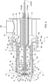
- the burner body 17 of the burner assembly 4 extends along a longitudinal axis A and comprises an air duct 40 centred on the axis A, a main burner 41, which extends around the air duct 40 and a stabilization burner 43, which is at least in part housed in the air passage duct 40.
- the burner body 17 further comprises a liquid fuel lance 45, which is also arranged along the air duct 40.
- the air duct 40 has an inlet 49 and an outlet 50.
- the air in the air duct 40 therefore, flows from the inlet 49 to the outlet 50.
- the air duct 40 comprises an inlet element 51, which comprises an inlet edge 52 defining the inlet 49 of the air duct 40, an outlet element 54, which comprises an outlet edge 55 defining the outlet 50 of the air duct 40, and an outlet swirler 56.
- the inlet element 51 and the outlet element 54 are coupled together.
- the outlet element 54 is keyed onto the inlet element 51 and wraps it for a stretch.
- connection elements may be present between the inlet element 51 and the outlet element 54.
- the inlet edge 51 has a preferably frusto-conical shape converging along the forward direction D.
- the inlet element 51 comprises an inner annular face 58, which defines an inlet portion 59 of the air duct having a constant passage section along the forward direction D.
- the outlet element 54 is annular and made of refractory material and is preferably defined by sectors that are assembled together.
- the outlet element 54 comprises an inner annular face 60 provided with a first inner portion 61 proximal to the outlet edge 55, which defines an outlet portion 63 of the air duct 40 having an increasing passage section along the forward direction D.
- the first inner portion 61 of the inner annular face 60 has a frusto-conical shape diverging along the forward direction D.
- first frusto-conical inner portion 61 is inclined with respect to the axial direction by an angle ⁇ comprised between 7° and 15°.
- the inner annular face 60 of the outlet element 54 is further provided with a second inner portion 64 which is configured so as to define a constant passage section along the forward direction D.
- the second inner portion 64 is arranged upstream of the first portion along the forward direction D.
- the second inner portion 64 is cylindrical and contiguous to the first inner portion 61.
- the outlet element 54 is further provided with a plurality of axial and through seats 66, which, as we will see in detail later, house portions of the main burner 41.
- the axial seats 66 are aligned along a circular path that surrounds the air duct 40.
- the axial seats 66 are arranged equidistant from each other.
- the seats 66 are arranged along non-axial directions and suitably inclined with respect to the longitudinal axis A (for example converging along the forward direction D or diverging along the forward direction D).
- the outlet element 54 is provided with an outer face 68 comprising a first cylindrical outer portion 69, which is proximal to the outlet edge 55, and a second annular outer portion 70, which extends transversely to the first cylindrical outer portion 69 and is provided with a plurality of holes 72 that define the outlet of the axial seats 66.
- the outer face 68 of the outlet element 54 also comprises a third outer portion 73, preferably cylindrical, which extends from the second annular outer portion 70 in a direction opposite to the forward direction D.
- the third outer portion 73 is coupled to a wall 75 of the boiler 2 (dashed and only partially visible).
- the wall 75 of the boiler 2 and the second annular outer portion 70 are therefore arranged substantially flush with each other.
- the inlet 49 faces a casing 78, which defines a plenum 79 supplied with air from the air supply duct 22 of the air supply system 18.
- the burner body 17 Inside the plenum 79 and at the inlet 49, the burner body 17 comprises a perforated pipe 80, which extends mainly externally to the air passage duct 40 and coaxially to the axis A.
- the perforated pipe 80 extends axially between the inlet 49 and an end wall 81 of the casing 78.
- a portion of the perforated pipe 80 is arranged within the air duct 40.
- the perforated pipe 80 helps to generate vorticity in the air flow passing through the inlet 49 by limiting the amount of air at the centre of the air duct 40.
- the burner body 17 also comprises an air flow distributing element 84 arranged within the casing 78.
- the air flow distributing element 84 is substantially cylindrical, centred on the axis A and arranged about at least a portion of the perforated pipe 80.
- the air flow distributing element 84 is fixed to the end wall 81 of the casing 78 and extends around the perforated pipe 80 until it reaches approximately half the axial length of the perforated pipe 80.
- the air flow distributing element 84 is dimensioned such that the distance between the perforated pipe 80 and the inner wall of the air flow distributing element 84 is such as to cause a homogeneous air distribution effect around the perforated pipe 80.
- the outlet swirler 56 is arranged in the outlet portion 63 of the air duct 40 and is supported by an axial conduit 85 that is concentric to the axis A.
- the outlet swirler 56 preferably faces the first inner portion 61 of the inner face of the outlet element 54 and is provided with a plurality of blades 86, which extend along respective radial directions and have one end 87a fixed to the axial conduit 85 and one end 87b fixed to an outer support ring 88.
- the outer support ring 88 is provided with a substantially cylindrical outer surface 89a, which faces the first inner portion 61 and is preferably provided, along the edge proximal to the outlet 49, with a plurality of teeth 89b which preferably project orthogonal to the outer surface 89a.
- the teeth 89b are preferably trapezoidal in shape.
- the outlet swirler 56 In use, the outlet swirler 56 generates, downstream, a low axial velocity zone to stabilize the diffusion flame created by the stabilization burner 43, as we will see later.
- a plurality of races 82 project radially from the axial conduit 85, which have a structural function and are fixed to the inlet element 51 of the air duct 40.
- the main burner 41 extends around the air duct 40 and comprises a plurality of fuel conduits 90 and a plurality of fuel injection nozzles 91 arranged at an end 92 of the respective fuel conduits 90.
- the fuel conduits 90 comprise an end portion 93, which comprises the end 92, and is housed in the seats 66.
- the fuel conduits 90 are cylindrical.
- Each fuel conduit 90 is provided with an end 94 opposite the end 92, which is connected to a respective manifold of the manifolds 34a, 34b and 34c.
- the end portion 93 is rotatably coupled to the remaining part of the fuel conduit 90 (detail not clearly visible in the accompanying figures).
- the end portion 93 is configured so as to rotate between -45° and 45° around its own axis B.
- a first group of fuel conduits 90a is connected to the first manifold 34a
- a second group of fuel conduits 90b is connected to the second manifold 34b
- a third group of fuel conduits 90b is connected to the third manifold 34b.
- the fuel conduits 90a of the first group are preferably interposed to the fuel conduits 90b of the second group and to the fuel conduits 90c of the third group.
- the fuel conduits 90a, 90b and 90c alternate along the circumference along which they are arranged. This allows an equal distribution of the fuels supplied by means of the main burner 41.
- the manifolds 34a, 34b and 34c are preferably defined by annular channels 98a, 98b, 98c, which extend externally to the casing 78.
- a wall of the manifolds 34a, 34b and 34c is defined by the wall of the casing 78.
- the manifolds 34a, 34b and 34c can be housed in the plenum 79 defined by the casing 78.
- the manifolds 34a, 34b and 34c are substantially identical.
- the manifolds can have different structure and different passage sections.
- Each injection nozzle 91 is provided with at least one injection hole 94 (better visible in the enlargement of Figure 3 ).
- the at least one injection hole 94 is arranged offset from the axis B of the respective end portion 93 of the fuel conduit 90.
- each fuel conduit 90 may be suitably adjusted so as to obtain an adjustment in the direction of injection of the fuel into the combustion chamber 3 through the injection holes 96.
- each fuel conduit 90 is adjusted during installation of the burner assembly or during ordinary and/or extraordinary maintenance operations.
- the stabilization burner 43 is, at least in part, housed in the air duct 40.
- the stabilization burner 43 is preferably supplied with natural gas or with gases of known characteristics that are stable over time and is connected to the stabilization line 28.
- the stabilization burner 43 extends substantially axially within the air duct 40.
- the stabilization burner 43 comprises two conduits 95 connected to the stabilization line 28, which extend in the air duct and are provided with a discharge portion 96 provided with a plurality of discharge nozzles 97.
- the conduits 95 are preferably arranged on opposite sides with respect to the axial conduit 85.
- the discharge portion 96 is arranged transverse to the axis A and the discharge nozzles 97 are arranged so as to inject fuel into the air duct 40 in a direction other than the forward direction D.
- each conduit 95 is arranged upstream of the outlet swirler 56.
- a limited amount of natural gas is injected into the air duct 40 through the stabilization burner 43 to produce, in diffusion mode, a stabilization flame particularly useful during the ignition, heating and full ignition phases.
- the injection of a very small portion of fuel into the central part of the burner assembly 4 can be useful for stabilizing the flame when the main burner 41 is supplied with fuels with low calorific value and low reactivity (e.g. waste gas) helping to keep the combustion stable.
- fuels with low calorific value and low reactivity e.g. waste gas
- Injecting a very small portion of fuel into the central part of the burner assembly 4 may also be useful when the main burner 41 is supplied with standard fuels (e.g. natural gas) because it creates a conventional diffusive combustion zone.
- standard fuels e.g. natural gas
- the presence of a flame is detectable even when the injection of the fuel into the outer portion can generate a "MILD" type combustion as a result of the demixing with more difficult flame detection.
- the burner body 17 further comprises a liquid fuel lance 45, which is also arranged along the air duct 40.
- liquid fuel lance 45 is preferably arranged in the axial conduit 85 which supports the outlet swirler 56 and is connected to the liquid fuel supply line 29.
- control device 20 regulates the fuel regulating valves 33a, 33b, 33c, the stabilizing fuel regulating valve 31, the liquid fuel regulating valve 32 depending on the availability of fuel and the energy demand to the boiler 2.
- control device 20 is configured to regulate the opening of the fuel regulating valves 33a, 33b, 33c on the basis of the energy demand of the boiler 2 and on the basis of characteristic parameters of the type of fuel that is supplied through the respective valve (e.g. Wobbe number, fuel pressure, fuel density, fuel calorific value).
- control device 20 defines the flow rate of each fuel to be supplied to the burner body 17 on the basis of the energy demand of the boiler 2 and on the basis of characteristic parameters of the fuel available.
- control device 20 regulates the flow rate supplied to the main burner 41, and therefore the opening of the fuel regulating valves 33a, 33b, 33c, on the basis of the following relationship:
- Q coll n ⁇ esimo PT n ⁇ esimo PC n ⁇ esimo
- the thermal power required for the fuel supplied to the n-th manifold is preferably defined a priori.
- the thermal power demand is distributed among the fuels so that only one of the fuels is supplied to the respective manifold being affected by the variations in thermal power demand, while the other manifolds (n-1) are preferably supplied with an amount of fuel that is substantially constant or subject to variations only in cases of actual need.
- n manifolds are all active, one manifold supplies fuel in modulating mode and is affected by variations in thermal power demand, while the other n-1 manifolds supply fuel in substantially constant mode or regulated according to criteria not related to thermal power demand.
- the calorific value of the fuel supplied to the n-th manifold is detected upstream of the respective fuel regulating valve 33a 33b 33c.
- the control device 20 is also configured to take into account the availability of current fuel and to optionally regulate the thermal power required for the fuel supplied to the n-th manifold PT (n-th) on the basis of actual availabilities.
- the control device 20 detects the availability of fuel based on pressure values detected on the fuel supply lines 30a 30b 30c upstream of the respective fuel regulating valves 33a 33b 33c. In this way, the control device is able to establish the actual availability of the fuels in the network and to regulate the thermal power required for the fuel supplied to the n-th manifold PT (n-th) if this exceeds the actual availability.
- connection valves 37a 37b 37c controlled by the control device 20.
- the control device 20 in fact, regulates the opening of the connection valves 37a 37b 37c to selectively put the manifolds 34a, 34b and 34c in connection on the basis of the energy demand of the boiler 2 and on the basis of characteristic data of the fuel present in the respective manifold 34a, 34b and 34c (for example the pressure of the fuel detected by means of pressure sensors 35a 35b 35c arranged downstream of the fuel regulating valves 33a 33b 33c) .
- connection valves 37a, 37b, 37c are carried out in order to obtain a distribution of the fuel on more than one manifold of the manifolds 34a, 34b and 34c and the closing is of course carried out in order to reduce said distribution.
- control device 20 is configured to open at least one connection valve of the connection valves 37a 37b 37c on the basis of the pressure values detected by the pressure sensors 35a 35b 35c downstream of the fuel regulating valves 33a 33b 33c.
- the opening of at least the connection valve connecting the manifold supplied by said line with a further manifold is carried out.
- connection valve once the opening of the at least one connection valve has been carried out, the closing of said valve will take place when the value of the data detected on the line (in the example considered herein the fuel pressure detected by means of pressure sensors 35a 35b 35c arranged downstream of the fuel regulating valves 33a 33b 33c) is again acceptable. In other words, if the pressure value drops to a second minimum threshold, then the connection valve that had been opened is closed again.
- connection valves 37a 37c is opened to connect the manifold 34a supplied by the line 30a to a further manifold (34b or 34c) .
- connection valve due to an excess of pressure on one of the connection valve lines will preferably coincide with the closing of the line regulating valve that supplies the manifold shared with the fuel supply line where an excess of pressure has occurred.
- the manifold 34b is used for the distribution of the first fuel.
- connection valve 37a is opened to put two fuel manifolds in communication in order to increase the outflow section of the injection nozzles and keep the pressure at the injection nozzles within acceptable limits.
- connection valves 37a 37b 37c allow any type of fuel to be managed even if it is not stable.
- the opening of the liquid fuel regulating valve 32 is regulated by the control device 20 on the basis of the energy demand of the boiler 2 and on the basis of the availability of liquid fuel and, if required, also on the basis of the indications of the need for fuel disposal (decided by the plant operator). Sometimes, in fact, it is required to dispose of liquid fuel with priority, especially when this represents, for example, a waste produced by the plant.
- the stabilizing fuel regulating valve 31 is regulated based on the operating conditions of the burner assembly 4 (i.e. on the basis of the energy demand of the boiler 2) and on the basis of the characteristic parameters of the fuel that is supplied to the main burner 41.
- control device 20 is configured to carry out a regulation of the flow rate of the stabilizing fuel based on, for example, the pressure of the fuels supplied to the fuel supply lines 30a 30b 30c.
- the pressure on which the flow rate control of the stabilizing fuel is based is carried out on the basis of the pressure detected upstream of the fuel regulating valves 33a, 33b, 33c.
- the stabilization burner 43 in fact, is activated in the ignition phases and optionally kept active or reactivated in the event that the characteristics of the fuel (or of the fuels) supplied to the main burner 41 detect particularly lean fuels.
- the stabilization burner 43 can be switched off (because it is not necessary) further reducing the overall NOx emissions.
- particularly reactive fuels e.g. hydrogen-based
- a burner assembly 400 in accordance with a second embodiment is shown in Figures 5 and 6 .
- the burner assembly 400 has a structure very similar to the burner assembly 4 and differs in some details which we specify hereinbelow.
- the burner assembly 400 is devoid of a liquid fuel burner and comprises a stabilization burner 443, which engages the axial conduit 85.
- the stabilization burner 443 injects fuel just downstream of the outlet swirler 56 and in the central position.
- the burner assembly 400 is further characterized by a different structure of the casing 478 (schematically represented in Figure 6 only), and by a different structure of the air flow distributing element 484 arranged within the casing 478.
- the casing 478 has a plenum 479 supplied with air from the air supply duct 22 of the air supply system 18.
- the casing 478 may be dimensioned so as to supply several air ducts of different burner assemblies.
- the air flow distributing element 484 has a substantially cylindrical structure and is centred on the axis A.
- the air flow distributing element 484 is fixed to the end wall 481 of the casing 478 and extends axially until it surrounds the inlet 49 of the air duct 40.
- the air flow distributing element 484 is defined by a plurality of axial fins 485, among which a plurality of air passages 486 are defined.
- the burner assembly 400 differs from the burner assembly 4 by a different aerodynamic conformation of the inlet element 451 of the air duct 40.
- the inlet element 451 comprises an inner annular face 458, which defines an inlet portion 459 of the air duct 40 having a variable passage section along the forward direction D.
- the inner annular face 458 of the inlet element 451 is shaped so as to define, along the forward direction D, a decreasing portion 460 having decreasing passage section, a constant portion 461 having constant passage section and an increasing portion 462 having increasing passage section.
- the conformation of the inner annular face 458 results in a better air distribution on the outer parts of the air duct 40 thanks to a slight flow acceleration effect.
- the burner assembly 400 comprises the fuel supply system 19 provided with the manifolds 34a, 34b and 34c as described and shown with reference to Figure 2 .
- the manifolds 34a, 34b, and 34c are arranged externally to the casing 478.
- the structure of the burner assembly 400 allows the use of fuel conduits 90 that are substantially longitudinal and arranged parallel to the axis A. This allows the adjustment of the position of the nozzles 91 also from the outside of the burner assembly 400 by rotating the fuel conduits 90.
- the end portions 93 of each fuel conduit 90 are, in this case, integral with the respective fuel conduit 90.
- the burner assembly 4, 400 according to the present invention therefore allows the generation of a demixed type combustion (with MILD characteristics) with low NOx emissions and allows to manage a plurality of fuels with time-varying characteristics.
- the main burner 41 injects fuel into a low-oxygen combustion zone, which surrounds an oxygen-rich combustion zone (i.e. the zone that faces the outlet 49 of the air duct 40 and is supplied by the stabilization burner 43 and optionally by the liquid fuel lance 45).
- a low-oxygen combustion zone which surrounds an oxygen-rich combustion zone (i.e. the zone that faces the outlet 49 of the air duct 40 and is supplied by the stabilization burner 43 and optionally by the liquid fuel lance 45).
- the comburent (air) coming from the air duct 40 and the fuel injected from the main burner 41 are substantially decoupled. This triggers an internal discharge gas recirculation (Flue Gas Recirculation) that dilutes the oxygen concentration. Due to the diluted conditions, the injection of fuel by the main burner 41 produces a combustion with significantly reduced temperature levels.
- the burner assembly 4, 400 according to the present invention is able to operate with several different gaseous fuels at the same time, exclusively with high reactivity fuel flows (e.g. 100% hydrogen) or even exclusively with low calorific value fuel flows.
- the combustion of lean gases is supported by the presence of the outlet element 54 in refractory material, which acts as a thermal flywheel to release energy in the case of lean fuels and to absorb energy in the case of fuels with high energy content.
Landscapes
- Engineering & Computer Science (AREA)
- Chemical & Material Sciences (AREA)
- Combustion & Propulsion (AREA)
- Mechanical Engineering (AREA)
- General Engineering & Computer Science (AREA)
Claims (12)
- Brenneranordnung für eine Kesseleinheit (1) zur Dampferzeugung, dadurch gekennzeichnet, dass die Brenneranordnung (4; 400) sich entlang einer Längsachse (A) erstreckt und umfasst:• einen mittig in der Längsache (A) angeordneten Luftkanal (40), in welchen bei Betrieb Luft in Durchlassrichtung (D) strömt; wobei der Luftkanal (40) mit einem Auslass (50) ausgestaltet ist, der in die Brennkammer (3) der Kesseleinheit (1) mündet;• eine Vielzahl von Brennstoffleitungen (90; 90a, 90b, 90c), in welche bei Betrieb mindestens ein Brennstoff in Durchlassrichtung (D) strömt;• eine Vielzahl von Brennstoffeinspritzdüsen (91), die um den Luftkanal (40) herum angeordnet sind, wobei jede Brennstoffeinspritzdüse (91) jeweils mit dem Endsegment (93) einer Brennstoffleitung (90; 90a, 90b, 90c) verbunden ist, die bei Betrieb Brennstoff in die Brennkammer (3) einleitet;• wobei der Auslass (50) des Luftkanals (40) den Brennstoffeinspritzdüsen (91) in Durchlassrichtung (D) nachgelagert ist; dadurch gekennzeichnet, dass• das Endsegment (93) mindestens einer Brennstoffleitung (90; 90a, 90b, 90c) um seine Achse (B) schwenkbar ist, um die Einspritzrichtung anpassen zu können.
- Brenneranordnung gemäß Anspruch 1, dadurch gekennzeichnet, dass das Endsegment (93) der Brennstoffleitungen (90; 90a, 90b, 90c) zylindrisch geformt ist.
- Brenneranordnung gemäß Anspruch 1 oder 2, dadurch gekennzeichnet, dass jede Brennstoffeinspritzdüse (91) mit mindestens einem Einspritzloch (94) versehen ist, das im Versatz zur Achse (B) des Endsegments (93) der Brennstoffleitung (90; 90a, 90b, 90c) angeordnet ist, mit welcher die Einspritzdüse (91) verbunden ist.
- Brenneranordnung gemäß einem der vorhergehenden Ansprüche, dadurch gekennzeichnet, dass die Endsegmente (93) der Brennstoffleitungen (90; 90a, 90b, 90c) parallel zueinander angeordnet sind.
- Brenneranordnung gemäß den Ansprüchen 1 bis 3, dadurch gekennzeichnet, dass die Endsegmente (93) der Brennstoffleitungen (90; 90a, 90b, 90c) jeweils in Durchlassrichtung (D) zusammenlaufen.
- Brenneranordnung gemäß den Ansprüchen 1 bis 3, dadurch gekennzeichnet, dass die Endsegmente (93) der Brennstoffleitungen (90; 90a, 90b, 90c) jeweils in Durchlassrichtung (D) auseinanderlaufen.
- Brenneranordnung gemäß einem der vorhergehenden Ansprüche, dadurch gekennzeichnet, dass der Luftkanal (40) ein ringförmiges Auslasselement (54) aus einem hitzebeständigen Material umfasst und mit einer Abströmkante (55) versehen ist, die den Auslass (50) des Luftkanals (40) darstellt; wobei das Auslasselement (54) mit einer Vielzahl von Leitungsführungen (66) versehen ist, in welchen die jeweiligen Endsegmente (93) der Brennstoffleitungen (90; 90a, 90b, 90c) gelagert sind.
- Brenneranordnung gemäß Anspruch 7, dadurch gekennzeichnet, dass die Leitungsführungen (66) kreisförmig um den Luftkanal (40) herum angeordnet sind.
- Brenneranordnung gemäß Anspruch 7 oder 8, dadurch gekennzeichnet, dass die Leitungsführungen (66) im gleichen Abstand zueinander angeordnet sind.
- Anordnung gemäß den Ansprüchen 7 bis 9, dadurch gekennzeichnet, dass das Auslasselement (54) mit einer Außenfläche (68) ausgestaltet ist umfassend ein erstes zylindrisches Außensegment (69), welches sich nahe der Abströmkante (55) befindet, sowie ein zweites zylindrisches Außensegment (70), welches sich querverlaufend zum ersten zylindrischen Außensegment (69) erstreckt und mit einer Vielzahl von Löchern (72) versehen ist, die den Auslass der Leitungsführungen (66) bilden.
- Kesseleinheit (1) zur Dampferzeugung umfassend einen Kessel (2), der mit einer Brennkammer (3) ausgestaltet ist und mindestens einer Brennereinheit (4; 400) gemäß einem der vorhergehenden Ansprüche.
- Verfahren zum Betrieb einer Brenneranordnung (4; 400) einer Kesseleinheit (1) zur Dampferzeugung, wobei die Brenneranordnung (4; 400) sich entlang einer Längsachse (A) erstreckt und umfasst:• einen mittig in der Längsache (A) angeordneten Luftkanal (40), in welchen bei Betrieb Luft in Durchlassrichtung (D) strömt; wobei der Luftkanal (40) mit einem Auslass (50) ausgestaltet ist, der in die Brennkammer (3) der Kesseleinheit (1) mündet;• eine Vielzahl von Brennstoffleitungen (90; 90a, 90b, 90c), in welche bei Betrieb mindestens ein Brennstoff in Durchlassrichtung (D) strömt;• eine Vielzahl von Brennstoffeinspritzdüsen (91), die um den Luftkanal (40) herum angeordnet sind, wobei jede Brennstoffeinspritzdüse (91) jeweils mit dem Endsegment (93) einer Brennstoffleitung (90; 90a, 90b, 90c) verbunden ist, die bei Betrieb Brennstoff in die Brennkammer (3) einleitet;• wobei der Auslass (50) des Luftkanals (40) den Brennstoffeinspritzdüsen (91) in Durchlassrichtung (D) nachgelagert ist; und wobei• das Endsegment (93) mindestens einer Brennstoffleitung (90; 90a, 90b, 90c) um seine Achse (B) schwenkbar ist, um die Einspritzrichtung anpassen zu können;wobei das eine Anpassung der abgewinkelten Position des Endsegments (93) mindestens einer Brennstoffleitung (90; 90a, 90b, 90c) ermöglicht, wenn die Brennereinrichtung (4; 400) nicht in Betrieb ist.
Applications Claiming Priority (1)
| Application Number | Priority Date | Filing Date | Title |
|---|---|---|---|
| IT102022000003722A IT202200003722A1 (it) | 2022-02-28 | 2022-02-28 | Gruppo bruciatore per un gruppo caldaia per la produzione di vapore e gruppo caldaia comprendente detto gruppo bruciatore |
Publications (3)
| Publication Number | Publication Date |
|---|---|
| EP4235026A1 EP4235026A1 (de) | 2023-08-30 |
| EP4235026B1 true EP4235026B1 (de) | 2024-10-30 |
| EP4235026C0 EP4235026C0 (de) | 2024-10-30 |
Family
ID=81648664
Family Applications (1)
| Application Number | Title | Priority Date | Filing Date |
|---|---|---|---|
| EP23158746.0A Active EP4235026B1 (de) | 2022-02-28 | 2023-02-27 | Brenneranordnung für eine kesseleinheit zur dampferzeugung und kesseleinheit mit der brenneranordnung |
Country Status (2)
| Country | Link |
|---|---|
| EP (1) | EP4235026B1 (de) |
| IT (1) | IT202200003722A1 (de) |
Family Cites Families (4)
| Publication number | Priority date | Publication date | Assignee | Title |
|---|---|---|---|---|
| DE1551827A1 (de) * | 1967-07-26 | 1970-09-17 | Zink Co John | Rotierender Gasbrenner |
| JP6168875B2 (ja) * | 2013-06-21 | 2017-07-26 | 日本ファーネス株式会社 | 燃料二段燃焼式バーナ装置及び燃料二段燃焼方法 |
| CZ2017140A3 (cs) * | 2017-03-13 | 2018-08-01 | Htt Engineering, Spol. S R.O. | Kombinovaný hořák pro dmychání oxidačního plynu a paliva do tavicí pece |
| WO2019049046A2 (en) * | 2017-09-05 | 2019-03-14 | John Zink Company, Llc | METHOD AND APPARATUS RELATED TO A LOW EMISSION NOX AND CO 2 COMBUSTION BURNER |
-
2022
- 2022-02-28 IT IT102022000003722A patent/IT202200003722A1/it unknown
-
2023
- 2023-02-27 EP EP23158746.0A patent/EP4235026B1/de active Active
Also Published As
| Publication number | Publication date |
|---|---|
| EP4235026A1 (de) | 2023-08-30 |
| EP4235026C0 (de) | 2024-10-30 |
| IT202200003722A1 (it) | 2023-08-28 |
Similar Documents
| Publication | Publication Date | Title |
|---|---|---|
| US11746704B2 (en) | Gas turbine combustor and its operating method | |
| EP3620719B1 (de) | Gasturbinenbrennkammer | |
| EP0547808B1 (de) | Brennkammer mit abgestufter Luftzufuhr | |
| CA2381018C (en) | Variable premix-lean burn combustor | |
| JP5406460B2 (ja) | 保炎マージンの範囲内で作動させるのを可能にするための方法及びシステム | |
| EP0836048B1 (de) | Brenner | |
| EP0017429A2 (de) | Brenner mit reduzierter Stickstoffoxydbildung | |
| EP2249081A1 (de) | Biomassenbrenner mit zentralem Luftstrahl | |
| US20130074515A1 (en) | Gas turbine engine system and method of providing a fuel supplied to one or more combustors in a gas turbine engine system | |
| EP4235027A1 (de) | Brennergruppe für einen kessel und verfahren zum betrieb der brennergruppe | |
| EP4235026B1 (de) | Brenneranordnung für eine kesseleinheit zur dampferzeugung und kesseleinheit mit der brenneranordnung | |
| US12510245B2 (en) | Burner assembly for a steam production boiler assembly and method for operating said burner assembly | |
| JP4409566B2 (ja) | 希薄予混合型燃焼装置とその制御方法 | |
| CN102859282B (zh) | 用于燃烧器的旋流生成器 | |
| US20220364725A1 (en) | Nozzle Configured To Deliver Gas Into Incinerator | |
| TWI876026B (zh) | 用於在一燃燒器中具有燃料流分布構件之一鍋爐的燃燒系統及燃燒方法 | |
| RU208401U1 (ru) | Газомазутная горелка с изменяемой формой амбразуры | |
| WO2011010160A1 (en) | Combustion apparatus | |
| RU215037U1 (ru) | Газомазутная горелка с нарезными каналами для интенсификации перемешивания | |
| RU214920U1 (ru) | Двухпоточная газомазутная горелка парового, водогрейного или термомасляного котла | |
| KR102893433B1 (ko) | 복합 연소 버너 및 이를 포함하는 연소 장치 | |
| KR102827280B1 (ko) | 연소 장치, 이를 포함하는 보일러 및 이의 연소 방법 | |
| TW202601019A (zh) | 用於燃燒設備的天然氣富集的方法 | |
| SU1516717A1 (ru) | Способ совместного сжигани топлив и горелочное устройство дл его осуществлени | |
| KR20250116726A (ko) | 가스 터빈 제어 장치 |
Legal Events
| Date | Code | Title | Description |
|---|---|---|---|
| PUAI | Public reference made under article 153(3) epc to a published international application that has entered the european phase |
Free format text: ORIGINAL CODE: 0009012 |
|
| STAA | Information on the status of an ep patent application or granted ep patent |
Free format text: STATUS: THE APPLICATION HAS BEEN PUBLISHED |
|
| AK | Designated contracting states |
Kind code of ref document: A1 Designated state(s): AL AT BE BG CH CY CZ DE DK EE ES FI FR GB GR HR HU IE IS IT LI LT LU LV MC ME MK MT NL NO PL PT RO RS SE SI SK SM TR |
|
| STAA | Information on the status of an ep patent application or granted ep patent |
Free format text: STATUS: REQUEST FOR EXAMINATION WAS MADE |
|
| 17P | Request for examination filed |
Effective date: 20240104 |
|
| RBV | Designated contracting states (corrected) |
Designated state(s): AL AT BE BG CH CY CZ DE DK EE ES FI FR GB GR HR HU IE IS IT LI LT LU LV MC ME MK MT NL NO PL PT RO RS SE SI SK SM TR |
|
| GRAP | Despatch of communication of intention to grant a patent |
Free format text: ORIGINAL CODE: EPIDOSNIGR1 |
|
| STAA | Information on the status of an ep patent application or granted ep patent |
Free format text: STATUS: GRANT OF PATENT IS INTENDED |
|
| RIC1 | Information provided on ipc code assigned before grant |
Ipc: F23D 14/24 20060101AFI20240422BHEP |
|
| INTG | Intention to grant announced |
Effective date: 20240527 |
|
| GRAS | Grant fee paid |
Free format text: ORIGINAL CODE: EPIDOSNIGR3 |
|
| GRAA | (expected) grant |
Free format text: ORIGINAL CODE: 0009210 |
|
| STAA | Information on the status of an ep patent application or granted ep patent |
Free format text: STATUS: THE PATENT HAS BEEN GRANTED |
|
| AK | Designated contracting states |
Kind code of ref document: B1 Designated state(s): AL AT BE BG CH CY CZ DE DK EE ES FI FR GB GR HR HU IE IS IT LI LT LU LV MC ME MK MT NL NO PL PT RO RS SE SI SK SM TR |
|
| REG | Reference to a national code |
Ref country code: GB Ref legal event code: FG4D |
|
| REG | Reference to a national code |
Ref country code: CH Ref legal event code: EP |
|
| REG | Reference to a national code |
Ref country code: IE Ref legal event code: FG4D |
|
| REG | Reference to a national code |
Ref country code: DE Ref legal event code: R096 Ref document number: 602023000843 Country of ref document: DE |
|
| U01 | Request for unitary effect filed |
Effective date: 20241119 |
|
| U07 | Unitary effect registered |
Designated state(s): AT BE BG DE DK EE FI FR IT LT LU LV MT NL PT RO SE SI Effective date: 20241122 |
|
| U20 | Renewal fee for the european patent with unitary effect paid |
Year of fee payment: 3 Effective date: 20250110 |
|
| PG25 | Lapsed in a contracting state [announced via postgrant information from national office to epo] |
Ref country code: IS Free format text: LAPSE BECAUSE OF FAILURE TO SUBMIT A TRANSLATION OF THE DESCRIPTION OR TO PAY THE FEE WITHIN THE PRESCRIBED TIME-LIMIT Effective date: 20250228 Ref country code: HR Free format text: LAPSE BECAUSE OF FAILURE TO SUBMIT A TRANSLATION OF THE DESCRIPTION OR TO PAY THE FEE WITHIN THE PRESCRIBED TIME-LIMIT Effective date: 20241030 |
|
| PG25 | Lapsed in a contracting state [announced via postgrant information from national office to epo] |
Ref country code: ES Free format text: LAPSE BECAUSE OF FAILURE TO SUBMIT A TRANSLATION OF THE DESCRIPTION OR TO PAY THE FEE WITHIN THE PRESCRIBED TIME-LIMIT Effective date: 20241030 |
|
| PG25 | Lapsed in a contracting state [announced via postgrant information from national office to epo] |
Ref country code: NO Free format text: LAPSE BECAUSE OF FAILURE TO SUBMIT A TRANSLATION OF THE DESCRIPTION OR TO PAY THE FEE WITHIN THE PRESCRIBED TIME-LIMIT Effective date: 20250130 |
|
| PG25 | Lapsed in a contracting state [announced via postgrant information from national office to epo] |
Ref country code: GR Free format text: LAPSE BECAUSE OF FAILURE TO SUBMIT A TRANSLATION OF THE DESCRIPTION OR TO PAY THE FEE WITHIN THE PRESCRIBED TIME-LIMIT Effective date: 20250131 |
|
| PG25 | Lapsed in a contracting state [announced via postgrant information from national office to epo] |
Ref country code: PL Free format text: LAPSE BECAUSE OF FAILURE TO SUBMIT A TRANSLATION OF THE DESCRIPTION OR TO PAY THE FEE WITHIN THE PRESCRIBED TIME-LIMIT Effective date: 20241030 |
|
| PG25 | Lapsed in a contracting state [announced via postgrant information from national office to epo] |
Ref country code: RS Free format text: LAPSE BECAUSE OF FAILURE TO SUBMIT A TRANSLATION OF THE DESCRIPTION OR TO PAY THE FEE WITHIN THE PRESCRIBED TIME-LIMIT Effective date: 20250130 |
|
| PG25 | Lapsed in a contracting state [announced via postgrant information from national office to epo] |
Ref country code: SM Free format text: LAPSE BECAUSE OF FAILURE TO SUBMIT A TRANSLATION OF THE DESCRIPTION OR TO PAY THE FEE WITHIN THE PRESCRIBED TIME-LIMIT Effective date: 20241030 |
|
| PG25 | Lapsed in a contracting state [announced via postgrant information from national office to epo] |
Ref country code: SK Free format text: LAPSE BECAUSE OF FAILURE TO SUBMIT A TRANSLATION OF THE DESCRIPTION OR TO PAY THE FEE WITHIN THE PRESCRIBED TIME-LIMIT Effective date: 20241030 |
|
| PG25 | Lapsed in a contracting state [announced via postgrant information from national office to epo] |
Ref country code: CZ Free format text: LAPSE BECAUSE OF FAILURE TO SUBMIT A TRANSLATION OF THE DESCRIPTION OR TO PAY THE FEE WITHIN THE PRESCRIBED TIME-LIMIT Effective date: 20241030 |
|
| PLBE | No opposition filed within time limit |
Free format text: ORIGINAL CODE: 0009261 |
|
| STAA | Information on the status of an ep patent application or granted ep patent |
Free format text: STATUS: NO OPPOSITION FILED WITHIN TIME LIMIT |
|
| PG25 | Lapsed in a contracting state [announced via postgrant information from national office to epo] |
Ref country code: MC Free format text: LAPSE BECAUSE OF FAILURE TO SUBMIT A TRANSLATION OF THE DESCRIPTION OR TO PAY THE FEE WITHIN THE PRESCRIBED TIME-LIMIT Effective date: 20241030 |
|
| 26N | No opposition filed |
Effective date: 20250731 |
|
| PG25 | Lapsed in a contracting state [announced via postgrant information from national office to epo] |
Ref country code: IE Free format text: LAPSE BECAUSE OF NON-PAYMENT OF DUE FEES Effective date: 20250227 |
|
| U20 | Renewal fee for the european patent with unitary effect paid |
Year of fee payment: 4 Effective date: 20260113 |