EP4235014A1 - Hydrogen tank support apparatus - Google Patents
Hydrogen tank support apparatus Download PDFInfo
- Publication number
- EP4235014A1 EP4235014A1 EP21883107.1A EP21883107A EP4235014A1 EP 4235014 A1 EP4235014 A1 EP 4235014A1 EP 21883107 A EP21883107 A EP 21883107A EP 4235014 A1 EP4235014 A1 EP 4235014A1
- Authority
- EP
- European Patent Office
- Prior art keywords
- storage tank
- hydrogen storage
- hydrogen
- lower block
- convex
- Prior art date
- Legal status (The legal status is an assumption and is not a legal conclusion. Google has not performed a legal analysis and makes no representation as to the accuracy of the status listed.)
- Pending
Links
Images




Classifications
-
- F—MECHANICAL ENGINEERING; LIGHTING; HEATING; WEAPONS; BLASTING
- F17—STORING OR DISTRIBUTING GASES OR LIQUIDS
- F17C—VESSELS FOR CONTAINING OR STORING COMPRESSED, LIQUEFIED OR SOLIDIFIED GASES; FIXED-CAPACITY GAS-HOLDERS; FILLING VESSELS WITH, OR DISCHARGING FROM VESSELS, COMPRESSED, LIQUEFIED, OR SOLIDIFIED GASES
- F17C13/00—Details of vessels or of the filling or discharging of vessels
- F17C13/08—Mounting arrangements for vessels
- F17C13/084—Mounting arrangements for vessels for small-sized storage vessels, e.g. compressed gas cylinders or bottles, disposable gas vessels, vessels adapted for automotive use
-
- B—PERFORMING OPERATIONS; TRANSPORTING
- B60—VEHICLES IN GENERAL
- B60K—ARRANGEMENT OR MOUNTING OF PROPULSION UNITS OR OF TRANSMISSIONS IN VEHICLES; ARRANGEMENT OR MOUNTING OF PLURAL DIVERSE PRIME-MOVERS IN VEHICLES; AUXILIARY DRIVES FOR VEHICLES; INSTRUMENTATION OR DASHBOARDS FOR VEHICLES; ARRANGEMENTS IN CONNECTION WITH COOLING, AIR INTAKE, GAS EXHAUST OR FUEL SUPPLY OF PROPULSION UNITS IN VEHICLES
- B60K15/00—Arrangement in connection with fuel supply of combustion engines or other fuel consuming energy converters, e.g. fuel cells; Mounting or construction of fuel tanks
- B60K15/03—Fuel tanks
- B60K15/063—Arrangement of tanks
- B60K15/067—Mounting of tanks
- B60K15/07—Mounting of tanks of gas tanks
-
- F—MECHANICAL ENGINEERING; LIGHTING; HEATING; WEAPONS; BLASTING
- F17—STORING OR DISTRIBUTING GASES OR LIQUIDS
- F17C—VESSELS FOR CONTAINING OR STORING COMPRESSED, LIQUEFIED OR SOLIDIFIED GASES; FIXED-CAPACITY GAS-HOLDERS; FILLING VESSELS WITH, OR DISCHARGING FROM VESSELS, COMPRESSED, LIQUEFIED, OR SOLIDIFIED GASES
- F17C13/00—Details of vessels or of the filling or discharging of vessels
- F17C13/04—Arrangement or mounting of valves
-
- F—MECHANICAL ENGINEERING; LIGHTING; HEATING; WEAPONS; BLASTING
- F17—STORING OR DISTRIBUTING GASES OR LIQUIDS
- F17C—VESSELS FOR CONTAINING OR STORING COMPRESSED, LIQUEFIED OR SOLIDIFIED GASES; FIXED-CAPACITY GAS-HOLDERS; FILLING VESSELS WITH, OR DISCHARGING FROM VESSELS, COMPRESSED, LIQUEFIED, OR SOLIDIFIED GASES
- F17C13/00—Details of vessels or of the filling or discharging of vessels
- F17C13/08—Mounting arrangements for vessels
-
- F—MECHANICAL ENGINEERING; LIGHTING; HEATING; WEAPONS; BLASTING
- F17—STORING OR DISTRIBUTING GASES OR LIQUIDS
- F17C—VESSELS FOR CONTAINING OR STORING COMPRESSED, LIQUEFIED OR SOLIDIFIED GASES; FIXED-CAPACITY GAS-HOLDERS; FILLING VESSELS WITH, OR DISCHARGING FROM VESSELS, COMPRESSED, LIQUEFIED, OR SOLIDIFIED GASES
- F17C2201/00—Vessel construction, in particular geometry, arrangement or size
- F17C2201/01—Shape
- F17C2201/0104—Shape cylindrical
- F17C2201/0109—Shape cylindrical with exteriorly curved end-piece
-
- F—MECHANICAL ENGINEERING; LIGHTING; HEATING; WEAPONS; BLASTING
- F17—STORING OR DISTRIBUTING GASES OR LIQUIDS
- F17C—VESSELS FOR CONTAINING OR STORING COMPRESSED, LIQUEFIED OR SOLIDIFIED GASES; FIXED-CAPACITY GAS-HOLDERS; FILLING VESSELS WITH, OR DISCHARGING FROM VESSELS, COMPRESSED, LIQUEFIED, OR SOLIDIFIED GASES
- F17C2201/00—Vessel construction, in particular geometry, arrangement or size
- F17C2201/03—Orientation
- F17C2201/035—Orientation with substantially horizontal main axis
-
- F—MECHANICAL ENGINEERING; LIGHTING; HEATING; WEAPONS; BLASTING
- F17—STORING OR DISTRIBUTING GASES OR LIQUIDS
- F17C—VESSELS FOR CONTAINING OR STORING COMPRESSED, LIQUEFIED OR SOLIDIFIED GASES; FIXED-CAPACITY GAS-HOLDERS; FILLING VESSELS WITH, OR DISCHARGING FROM VESSELS, COMPRESSED, LIQUEFIED, OR SOLIDIFIED GASES
- F17C2201/00—Vessel construction, in particular geometry, arrangement or size
- F17C2201/05—Size
- F17C2201/056—Small (<1 m3)
-
- F—MECHANICAL ENGINEERING; LIGHTING; HEATING; WEAPONS; BLASTING
- F17—STORING OR DISTRIBUTING GASES OR LIQUIDS
- F17C—VESSELS FOR CONTAINING OR STORING COMPRESSED, LIQUEFIED OR SOLIDIFIED GASES; FIXED-CAPACITY GAS-HOLDERS; FILLING VESSELS WITH, OR DISCHARGING FROM VESSELS, COMPRESSED, LIQUEFIED, OR SOLIDIFIED GASES
- F17C2205/00—Vessel construction, in particular mounting arrangements, attachments or identifications means
- F17C2205/01—Mounting arrangements
- F17C2205/0123—Mounting arrangements characterised by number of vessels
- F17C2205/013—Two or more vessels
-
- F—MECHANICAL ENGINEERING; LIGHTING; HEATING; WEAPONS; BLASTING
- F17—STORING OR DISTRIBUTING GASES OR LIQUIDS
- F17C—VESSELS FOR CONTAINING OR STORING COMPRESSED, LIQUEFIED OR SOLIDIFIED GASES; FIXED-CAPACITY GAS-HOLDERS; FILLING VESSELS WITH, OR DISCHARGING FROM VESSELS, COMPRESSED, LIQUEFIED, OR SOLIDIFIED GASES
- F17C2205/00—Vessel construction, in particular mounting arrangements, attachments or identifications means
- F17C2205/01—Mounting arrangements
- F17C2205/0123—Mounting arrangements characterised by number of vessels
- F17C2205/013—Two or more vessels
- F17C2205/0134—Two or more vessels characterised by the presence of fluid connection between vessels
- F17C2205/0142—Two or more vessels characterised by the presence of fluid connection between vessels bundled in parallel
-
- F—MECHANICAL ENGINEERING; LIGHTING; HEATING; WEAPONS; BLASTING
- F17—STORING OR DISTRIBUTING GASES OR LIQUIDS
- F17C—VESSELS FOR CONTAINING OR STORING COMPRESSED, LIQUEFIED OR SOLIDIFIED GASES; FIXED-CAPACITY GAS-HOLDERS; FILLING VESSELS WITH, OR DISCHARGING FROM VESSELS, COMPRESSED, LIQUEFIED, OR SOLIDIFIED GASES
- F17C2205/00—Vessel construction, in particular mounting arrangements, attachments or identifications means
- F17C2205/01—Mounting arrangements
- F17C2205/0153—Details of mounting arrangements
-
- F—MECHANICAL ENGINEERING; LIGHTING; HEATING; WEAPONS; BLASTING
- F17—STORING OR DISTRIBUTING GASES OR LIQUIDS
- F17C—VESSELS FOR CONTAINING OR STORING COMPRESSED, LIQUEFIED OR SOLIDIFIED GASES; FIXED-CAPACITY GAS-HOLDERS; FILLING VESSELS WITH, OR DISCHARGING FROM VESSELS, COMPRESSED, LIQUEFIED, OR SOLIDIFIED GASES
- F17C2205/00—Vessel construction, in particular mounting arrangements, attachments or identifications means
- F17C2205/01—Mounting arrangements
- F17C2205/0153—Details of mounting arrangements
- F17C2205/0192—Details of mounting arrangements with external bearing means
-
- F—MECHANICAL ENGINEERING; LIGHTING; HEATING; WEAPONS; BLASTING
- F17—STORING OR DISTRIBUTING GASES OR LIQUIDS
- F17C—VESSELS FOR CONTAINING OR STORING COMPRESSED, LIQUEFIED OR SOLIDIFIED GASES; FIXED-CAPACITY GAS-HOLDERS; FILLING VESSELS WITH, OR DISCHARGING FROM VESSELS, COMPRESSED, LIQUEFIED, OR SOLIDIFIED GASES
- F17C2221/00—Handled fluid, in particular type of fluid
- F17C2221/01—Pure fluids
- F17C2221/012—Hydrogen
-
- F—MECHANICAL ENGINEERING; LIGHTING; HEATING; WEAPONS; BLASTING
- F17—STORING OR DISTRIBUTING GASES OR LIQUIDS
- F17C—VESSELS FOR CONTAINING OR STORING COMPRESSED, LIQUEFIED OR SOLIDIFIED GASES; FIXED-CAPACITY GAS-HOLDERS; FILLING VESSELS WITH, OR DISCHARGING FROM VESSELS, COMPRESSED, LIQUEFIED, OR SOLIDIFIED GASES
- F17C2223/00—Handled fluid before transfer, i.e. state of fluid when stored in the vessel or before transfer from the vessel
- F17C2223/01—Handled fluid before transfer, i.e. state of fluid when stored in the vessel or before transfer from the vessel characterised by the phase
- F17C2223/0107—Single phase
- F17C2223/0123—Single phase gaseous, e.g. CNG, GNC
-
- F—MECHANICAL ENGINEERING; LIGHTING; HEATING; WEAPONS; BLASTING
- F17—STORING OR DISTRIBUTING GASES OR LIQUIDS
- F17C—VESSELS FOR CONTAINING OR STORING COMPRESSED, LIQUEFIED OR SOLIDIFIED GASES; FIXED-CAPACITY GAS-HOLDERS; FILLING VESSELS WITH, OR DISCHARGING FROM VESSELS, COMPRESSED, LIQUEFIED, OR SOLIDIFIED GASES
- F17C2223/00—Handled fluid before transfer, i.e. state of fluid when stored in the vessel or before transfer from the vessel
- F17C2223/03—Handled fluid before transfer, i.e. state of fluid when stored in the vessel or before transfer from the vessel characterised by the pressure level
- F17C2223/036—Very high pressure (>80 bar)
-
- F—MECHANICAL ENGINEERING; LIGHTING; HEATING; WEAPONS; BLASTING
- F17—STORING OR DISTRIBUTING GASES OR LIQUIDS
- F17C—VESSELS FOR CONTAINING OR STORING COMPRESSED, LIQUEFIED OR SOLIDIFIED GASES; FIXED-CAPACITY GAS-HOLDERS; FILLING VESSELS WITH, OR DISCHARGING FROM VESSELS, COMPRESSED, LIQUEFIED, OR SOLIDIFIED GASES
- F17C2260/00—Purposes of gas storage and gas handling
- F17C2260/01—Improving mechanical properties or manufacturing
- F17C2260/018—Adapting dimensions
-
- F—MECHANICAL ENGINEERING; LIGHTING; HEATING; WEAPONS; BLASTING
- F17—STORING OR DISTRIBUTING GASES OR LIQUIDS
- F17C—VESSELS FOR CONTAINING OR STORING COMPRESSED, LIQUEFIED OR SOLIDIFIED GASES; FIXED-CAPACITY GAS-HOLDERS; FILLING VESSELS WITH, OR DISCHARGING FROM VESSELS, COMPRESSED, LIQUEFIED, OR SOLIDIFIED GASES
- F17C2270/00—Applications
- F17C2270/01—Applications for fluid transport or storage
- F17C2270/0165—Applications for fluid transport or storage on the road
- F17C2270/0168—Applications for fluid transport or storage on the road by vehicles
-
- F—MECHANICAL ENGINEERING; LIGHTING; HEATING; WEAPONS; BLASTING
- F17—STORING OR DISTRIBUTING GASES OR LIQUIDS
- F17C—VESSELS FOR CONTAINING OR STORING COMPRESSED, LIQUEFIED OR SOLIDIFIED GASES; FIXED-CAPACITY GAS-HOLDERS; FILLING VESSELS WITH, OR DISCHARGING FROM VESSELS, COMPRESSED, LIQUEFIED, OR SOLIDIFIED GASES
- F17C2270/00—Applications
- F17C2270/01—Applications for fluid transport or storage
- F17C2270/0165—Applications for fluid transport or storage on the road
- F17C2270/0168—Applications for fluid transport or storage on the road by vehicles
- F17C2270/0178—Cars
-
- Y—GENERAL TAGGING OF NEW TECHNOLOGICAL DEVELOPMENTS; GENERAL TAGGING OF CROSS-SECTIONAL TECHNOLOGIES SPANNING OVER SEVERAL SECTIONS OF THE IPC; TECHNICAL SUBJECTS COVERED BY FORMER USPC CROSS-REFERENCE ART COLLECTIONS [XRACs] AND DIGESTS
- Y02—TECHNOLOGIES OR APPLICATIONS FOR MITIGATION OR ADAPTATION AGAINST CLIMATE CHANGE
- Y02E—REDUCTION OF GREENHOUSE GAS [GHG] EMISSIONS, RELATED TO ENERGY GENERATION, TRANSMISSION OR DISTRIBUTION
- Y02E60/00—Enabling technologies; Technologies with a potential or indirect contribution to GHG emissions mitigation
- Y02E60/30—Hydrogen technology
- Y02E60/32—Hydrogen storage
Definitions
- the present disclosure relates to a hydrogen tank support apparatus, and more particularly, to a hydrogen tank support apparatus which can stably support expansion of a hydrogen storage tank and a change in the axis of the hydrogen storage tank.
- a hydrogen storage tank is a canister for storing a large volume of hydrogen in a compressed state and supplies hydrogen to a fuel cell electric vehicle (FCEV).
- FCEV fuel cell electric vehicle
- a mounting block for supporting a hydrogen storage tank according to the related art has problems that the assembly time is increased due to a large number of components, and productivity is low such that the price competitiveness is low. Also, there is a problem that the size of a snap ring configured to support a nozzle should be increased with an increase in the size of the hydrogen storage tank and an increase in the diameter of the nozzle. Accordingly, there is a need to address such problems.
- the present disclosure provides a hydrogen tank support apparatus which can stably support expansion of a hydrogen storage tank and a change in the axis of the hydrogen storage tank.
- the present disclosure provides a hydrogen tank support apparatus including: a hydrogen storage tank; a frame portion on which the hydrogen storage tank is seated; and a sliding block portion configured to fix a nozzle portion of the hydrogen storage tank to the frame portion, wherein the sliding block portion includes a lower block portion fixed to the frame portion, an upper block portion coupled to the lower block portion in a concave-convex manner so that movement of the hydrogen storage tank is limited in a longitudinal direction and a width direction of the hydrogen storage tank, and a slide ball portion configured to surround an outer side surface of the nozzle portion, interposed between the lower block portion and the upper block portion, and configured to rotatably support the nozzle portion.
- the lower block portion may include: a lower block base portion fixed to the frame portion; a lower block body portion formed to extend from the lower block base portion toward the upper block portion and configured to accommodate the slide ball portion; and a convex portion formed to be convex from the lower block body portion toward the upper block portion and coupled to the upper block portion in a concave-convex manner.
- the convex portion may be formed to protrude from an outermost side of the lower block body portion in the longitudinal direction of the hydrogen storage tank.
- the upper block portion may include: an upper block body portion seated on the lower block body portion and configured to accommodate the slide ball portion; and a concave portion formed to be concave in the upper block body portion to face the convex portion and coupled to the convex portion in a concave-convex manner.
- the concave portion may include: a concave groove portion configured to accommodate the convex portion; and a catching step portion formed to protrude from the concave groove portion to surround an outer side surface of the convex portion.
- the catching step portion may be formed on the concave groove portion to surround the outer side surface of the convex portion in the longitudinal direction of the hydrogen storage tank.
- the catching step portion may be formed on the concave groove portion to surround three sides of the outer side surface of the convex portion.
- the sliding block portion may further include: a first fastening portion configured to fasten the lower block portion and the upper block portion to each other; and a second fastening portion configured to fasten the lower block portion and the frame portion to each other.
- the hydrogen tank support apparatus may further include a fixing block portion configured to fix the hydrogen storage tank to the frame portion.
- a nozzle portion of a hydrogen storage tank can be stably supported while the number of components for stably supporting the nozzle portion of the hydrogen storage tank is reduced, and assembly time can be reduced, thus improving productivity.
- the nozzle portion of the hydrogen storage tank can be prevented from being detached.
- FIG. 1 is a perspective view from one side schematically illustrating a hydrogen tank support apparatus according to one embodiment of the present disclosure
- FIG. 2 is a perspective view from another side schematically illustrating the hydrogen tank support apparatus according to one embodiment of the present disclosure
- FIG. 3 is a schematic enlarged view of portion "A" of FIG. 1
- FIG. 4 is a schematic enlarged view of portion "B" of FIG. 2
- FIG. 5 is an exploded perspective view schematically illustrating the hydrogen tank support apparatus according to one embodiment of the present disclosure
- FIG. 6 is a perspective view schematically illustrating a sliding block portion according to one embodiment of the present disclosure
- FIG. 7 is an exploded perspective view schematically illustrating the sliding block portion according to one embodiment of the present disclosure
- FIG. 1 is a perspective view from one side schematically illustrating a hydrogen tank support apparatus according to one embodiment of the present disclosure
- FIG. 2 is a perspective view from another side schematically illustrating the hydrogen tank support apparatus according to one embodiment of the present disclosure
- FIG. 3 is a schematic
- FIG. 8 is a schematic enlarged view of portion "C" of FIG. 7
- FIG. 9 is an exploded perspective view schematically illustrating a sliding block portion according to another embodiment of the present disclosure
- FIG. 10 is a schematic enlarged view of portion "D" of FIG. 9 .
- the hydrogen tank support apparatus includes a hydrogen storage tank 10, a frame portion 20, a fixing block portion 30, and a sliding block portion 40.
- the hydrogen storage tank 10 is a canister for storing hydrogen in a compressed state in an inner space thereof.
- the hydrogen storage tank 10 allows a fuel cell electric vehicle to be charged with hydrogen and produce electricity necessary to run the vehicle.
- the hydrogen storage tank 10 is formed in a cylindrical shape having both ends formed in an elliptical shape to prevent damage due to pressure of hydrogen.
- the frame portion 20 supports the hydrogen storage tank 10 to prevent the hydrogen storage tank 10 from being detached from the fuel cell electric vehicle.
- the hydrogen storage tank 10 is seated on one side surface (an upper side surface based on FIG. 1 ) of the frame portion 20.
- the fixing block portion 30 fixes the hydrogen storage tank 10 to the frame portion 20.
- the fixing block portion 30 fixes the hydrogen storage tank 10 to the frame portion 20 to prevent the hydrogen storage tank 10 from being detached from the frame portion 20 due to an external impact or the like.
- the fixing block portion 30 is fixed to the frame portion 20 by a third fastening portion 600, and the opening or closing of the fixing block portion 30 is adjusted using the third fastening portion 600.
- the third fastening portion 600 is formed of a bolt, a screw, or the like having screw threads formed on an outer side surface thereof.
- each of a first fastening portion 400 and a second fastening portion 500 which will be described below, is also formed of a bolt, a screw, or the like having screw threads formed on an outer side surface thereof.
- the sliding block portion 40 fixes a nozzle portion 11 of the hydrogen storage tank 10 to the frame portion 20.
- the sliding block portion 40 may absorb a change amount thereof to stably support the hydrogen storage tank 10.
- the nozzle portion 11 allows hydrogen to be sprayed from the hydrogen storage tank 10 and includes a nozzle 13 and an opening/closing portion 15. Hydrogen is sprayed from the hydrogen storage tank 10 through the nozzle 13. Screw threads are formed on an inner side surface of the nozzle 13 to allow the opening/closing portion 15 to be detachable.
- the opening/closing portion 15 is screw-fastened to the inner side surface of the nozzle 13 and has screw threads formed on an outer side surface thereof.
- the sliding block portion 40 includes a lower block portion 100, an upper block portion 200, a slide ball portion 300, the first fastening portion 400, and the second fastening portion 500.
- the lower block portion 100 is fixed to the frame portion 20.
- the lower block portion 100 is fixed to the frame portion 20 by the second fastening portion 500 or by being welded to the frame portion 20.
- the lower block portion 100 includes a lower block base portion 110, a lower block body portion 120, and a convex portion 130.
- the lower block base portion 110 is seated on one side surface (an upper side surface based on FIG. 3 ) of the frame portion 20 and fixed to the frame portion 20.
- the lower block base portion 110 is fixed to the frame portion 20 by the second fastening portion 500 or by being welded to the frame portion 20.
- the lower block base portion 110 is disposed orthogonal to the longitudinal direction of the hydrogen storage tank 10.
- a first lower through-hole portion 111, through which the second fastening portion 500 passes, is formed to pass through both ends of the lower block base portion 110. Screw threads may not be formed in an inner side surface of the first lower through-hole portion 111 to allow the second fastening portion 500 to pass therethrough, or screw threads configured to be screw-fastened to the second fastening portion 500 may be formed in the inner side surface of the first lower through-hole portion 111.
- the second fastening portion 500 passes through the first lower through-hole portion 111 or is screw-fastened to the first lower through-hole portion 111 to be screw-fastened to the frame portion 20. Accordingly, the lower block base portion 110 of the lower block portion 100 and the frame portion 20 may be integrally fixed by the second fastening portion 500.
- the lower block body portion 120 is formed to extend from the lower block base portion 110 toward the upper block portion 200 and accommodates the slide ball portion 300. To allow the second fastening portion 500 to be screw-fastened, the lower block body portion 120 is formed to extend in a stepped manner from the lower block base portion 110.
- a lower accommodating groove portion 123 formed in a hemispherical shape is formed in one side surface (an upper side surface based on FIG. 7 ) of the lower block body portion 120 to accommodate the slide ball portion 300.
- the lower accommodating groove portion 123 is formed as a three-dimensional concave curved surface that corresponds to an outer side surface of the slide ball portion 300.
- the convex portion 130 is formed to be convex from the lower block body portion 120 toward a concave portion 220 of the upper block portion 200 and is coupled to the concave portion 220 of the upper block portion 200 in a concave-convex manner. Since the convex portion 130 is coupled to the concave portion 220 of the upper block portion 200 in a concave-convex manner, the coupling time can be reduced, and productivity can be improved.
- the convex portion 130 is formed to protrude from the lower block base portion 110 in a longitudinal direction of the lower block base portion 110 (the X-axis direction based on FIG. 7 ).
- a second lower through-hole portion 121 configured to communicate with an upper through-hole portion 211 of the upper block portion 200 is formed in the convex portion 130 and the lower block body portion 120.
- Screw threads configured to be screw-fastened to the first fastening portion 400 may be formed on an inner side surface of the second lower through-hole portion 121.
- the first fastening portion 400 may be screw-fastened to the second lower through-hole portion 121 and integrally fix the upper block portion 200 and the lower block portion 100.
- the upper block portion 200 is coupled to the lower block portion 100 in a concave-convex manner so that movement of the hydrogen storage tank 10 is limited in the longitudinal direction thereof (the Y-axis direction based on FIG. 1 ).
- the upper block portion 200 includes an upper block body portion 210 and the concave portion 220.
- the convex portion 130 is formed to protrude from an outermost side of the lower block body portion 120 in the longitudinal direction of the hydrogen storage tank 10.
- the convex portion 130 is formed to protrude to be disposed at the outermost side of an upper side of the lower block body portion 120.
- the upper block portion 200 is coupled to the lower block portion 100 in a concave-convex manner so that movement of the hydrogen storage tank 10 is limited in the longitudinal direction thereof (the Y-axis direction based on FIG. 1 ) and a width direction thereof (the X-axis direction based on FIG. 1 ).
- the upper block portion 200 includes the upper block body portion 210 and the concave portion 220.
- the upper block body portion 210 is seated on the lower block body portion 120 and accommodates the slide ball portion 300.
- the upper through-hole portion 211 communicating with the second lower through-hole portion 121 of the lower block portion 100 is formed in the upper block body portion 210.
- the first fastening portion 400 may pass through an inner side surface of the upper through-hole portion 211, or screw threads configured to be screw-fastened to the first fastening portion 400 may be formed on the inner side surface of the upper through-hole portion 211. By passing through the upper through-hole portion 211 or being screw-fastened thereto, the first fastening portion 400 may be screw-fastened to the second lower through-hole portion 121 and integrally fix the upper block portion 200 and the lower block portion 100.
- An upper accommodating groove portion 213 formed in a hemispherical shape is formed in one side surface (a left side surface based on FIG. 7 ) of the upper block body portion 210 to accommodate the slide ball portion 300.
- the upper accommodating groove portion 213 is formed as a three-dimensional concave curved surface that corresponds to the outer side surface of the slide ball portion 300.
- the concave portion 220 is formed to be concave in the upper block body portion 210 to face the convex portion 130 and is coupled to the convex portion 130 in a concave-convex manner.
- the concave portion 220 includes a concave groove portion 221 and a catching step portion 223.
- the concave groove portion 221 is for accommodating the convex portion 130 and is formed to be concave to correspond to the shape of the convex portion 130.
- the catching step portion 223 is formed to protrude from the concave groove portion 221 and surrounds an outer side surface of the convex portion 130.
- the catching step portion 223 is formed on the concave groove portion 221 to surround the outer side surface of the convex portion 130 in the longitudinal direction of the hydrogen storage tank 10 (the Y-axis direction based on FIG. 5 ). That is, the catching step portion 223 is formed to surround the convex portion 130 in the Y-axis direction based on FIG. 7 so that movement of the hydrogen storage tank 10 in the longitudinal direction thereof is limited.
- the concave groove portion 221 is for accommodating the convex portion 130 and is formed to be concave to correspond to the shape of the convex portion 130.
- the catching step portion 223 is formed to protrude from the concave groove portion 221 and surrounds three sides of the outer side surface of the convex portion 130. That is, the catching step portion 223 is formed to surround two sides of the convex portion 130 in the Y-axis direction based on FIG. 7 and surround one side of the convex portion 130 disposed at an inner side of the lower block body portion 120 so that movement of the hydrogen storage tank 10 in the longitudinal direction and width direction thereof is limited.
- the slide ball portion 300 is formed in a hollow ring shape and has an outer side surface formed as a three-dimensional curved surface.
- the slide ball portion 300 surrounds an outer side surface of the nozzle 13 of the nozzle portion 11, is interposed between the lower block portion 100 and the upper block portion 200, and rotatably supports the nozzle 13 of the nozzle portion 11.
- the slide ball portion 300 may be interposed to be capable of three-dimensional rotation between the lower accommodating groove portion 123 of the lower block portion 100 and the upper accommodating groove portion 213 of the upper block portion 200 and may three-dimensionally rotate in relation to the nozzle 13 of the nozzle portion 11, expansion of the hydrogen storage tank 10, or the like.
- the first fastening portion 400 fastens the lower block portion 100 and the upper block portion 200 to each other
- the second fastening portion 500 fastens the lower block portion 100 and the frame portion 20 to each other.
- the first fastening portion 400 may be screw-fastened to the second lower through-hole portion 121 and integrally fix the upper block portion 200 and the lower block portion 100.
- the second fastening portion 500 By passing through the first lower through-hole portion 111 or being screw-fastened to the first lower through-hole portion 111, the second fastening portion 500 is screw-fastened to the frame portion 20. Accordingly, the lower block base portion 110 of the lower block portion 100 and the frame portion 20 may be integrally fixed by the second fastening portion 500.
- a nozzle portion of a hydrogen storage tank can be stably supported while the number of components for stably supporting the nozzle portion of the hydrogen storage tank is reduced, and assembly time can be reduced, thus improving productivity.
- the nozzle portion of the hydrogen storage tank can be prevented from being detached.
Landscapes
- Engineering & Computer Science (AREA)
- Mechanical Engineering (AREA)
- General Engineering & Computer Science (AREA)
- Life Sciences & Earth Sciences (AREA)
- Sustainable Development (AREA)
- Sustainable Energy (AREA)
- Chemical & Material Sciences (AREA)
- Combustion & Propulsion (AREA)
- Transportation (AREA)
- Filling Or Discharging Of Gas Storage Vessels (AREA)
Abstract
Description
- The present disclosure relates to a hydrogen tank support apparatus, and more particularly, to a hydrogen tank support apparatus which can stably support expansion of a hydrogen storage tank and a change in the axis of the hydrogen storage tank.
- A hydrogen storage tank is a canister for storing a large volume of hydrogen in a compressed state and supplies hydrogen to a fuel cell electric vehicle (FCEV).
- While the energy density per weight of hydrogen is three to four times that of gasoline, the energy density per area of hydrogen is around 25% of that of gasoline. Thus, hydrogen should be stored in a maximally compressed state in a hydrogen storage tank for an efficient use of the hydrogen storage tank.
- A mounting block for supporting a hydrogen storage tank according to the related art has problems that the assembly time is increased due to a large number of components, and productivity is low such that the price competitiveness is low. Also, there is a problem that the size of a snap ring configured to support a nozzle should be increased with an increase in the size of the hydrogen storage tank and an increase in the diameter of the nozzle. Accordingly, there is a need to address such problems.
- The related art of the present disclosure has been disclosed in
Korean Unexamined Patent Application Publication No. 10-2019-0016917 (Date of Publication: February 19, 2019 - The present disclosure provides a hydrogen tank support apparatus which can stably support expansion of a hydrogen storage tank and a change in the axis of the hydrogen storage tank.
- The present disclosure provides a hydrogen tank support apparatus including: a hydrogen storage tank; a frame portion on which the hydrogen storage tank is seated; and a sliding block portion configured to fix a nozzle portion of the hydrogen storage tank to the frame portion, wherein the sliding block portion includes a lower block portion fixed to the frame portion, an upper block portion coupled to the lower block portion in a concave-convex manner so that movement of the hydrogen storage tank is limited in a longitudinal direction and a width direction of the hydrogen storage tank, and a slide ball portion configured to surround an outer side surface of the nozzle portion, interposed between the lower block portion and the upper block portion, and configured to rotatably support the nozzle portion.
- In the present disclosure, the lower block portion may include: a lower block base portion fixed to the frame portion; a lower block body portion formed to extend from the lower block base portion toward the upper block portion and configured to accommodate the slide ball portion; and a convex portion formed to be convex from the lower block body portion toward the upper block portion and coupled to the upper block portion in a concave-convex manner.
- In the present disclosure, the convex portion may be formed to protrude from an outermost side of the lower block body portion in the longitudinal direction of the hydrogen storage tank.
- In the present disclosure, the upper block portion may include: an upper block body portion seated on the lower block body portion and configured to accommodate the slide ball portion; and a concave portion formed to be concave in the upper block body portion to face the convex portion and coupled to the convex portion in a concave-convex manner.
- In the present disclosure, the concave portion may include: a concave groove portion configured to accommodate the convex portion; and a catching step portion formed to protrude from the concave groove portion to surround an outer side surface of the convex portion.
- In the present disclosure, the catching step portion may be formed on the concave groove portion to surround the outer side surface of the convex portion in the longitudinal direction of the hydrogen storage tank.
- In the present disclosure, the catching step portion may be formed on the concave groove portion to surround three sides of the outer side surface of the convex portion.
- In the present disclosure, the sliding block portion may further include: a first fastening portion configured to fasten the lower block portion and the upper block portion to each other; and a second fastening portion configured to fasten the lower block portion and the frame portion to each other.
- In the present disclosure, the hydrogen tank support apparatus may further include a fixing block portion configured to fix the hydrogen storage tank to the frame portion.
- By a hydrogen tank support apparatus according to the present disclosure, a nozzle portion of a hydrogen storage tank can be stably supported while the number of components for stably supporting the nozzle portion of the hydrogen storage tank is reduced, and assembly time can be reduced, thus improving productivity.
- Also, according to the present disclosure, the nozzle portion of the hydrogen storage tank can be prevented from being detached.
-
-
FIG. 1 is a perspective view from one side schematically illustrating a hydrogen tank support apparatus according to one embodiment of the present disclosure. -
FIG. 2 is a perspective view from another side schematically illustrating the hydrogen tank support apparatus according to one embodiment of the present disclosure. -
FIG. 3 is a schematic enlarged view of portion "A" ofFIG. 1 . -
FIG. 4 is a schematic enlarged view of portion "B" ofFIG. 2 . -
FIG. 5 is an exploded perspective view schematically illustrating the hydrogen tank support apparatus according to one embodiment of the present disclosure. -
FIG. 6 is a perspective view schematically illustrating a sliding block portion according to one embodiment of the present disclosure. -
FIG. 7 is an exploded perspective view schematically illustrating the sliding block portion according to one embodiment of the present disclosure. -
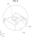
FIG. 8 is a schematic enlarged view of portion "C" ofFIG. 7 . -
FIG. 9 is an exploded perspective view schematically illustrating a sliding block portion according to another embodiment of the present disclosure. -
FIG. 10 is a schematic enlarged view of portion "D" ofFIG. 9 . - Hereinafter, one embodiment of a hydrogen tank support apparatus according to the present disclosure will be described with reference to the accompanying drawings. In such a process, thicknesses of lines, sizes of elements, or the like illustrated in the drawings may be exaggerated for clarity and convenience of description.
- Also, terms used below are terms defined in consideration of functions in the present disclosure and may be changed according to the intention or practice of a user or operator. Therefore, such terms should be defined on the basis of the content throughout the specification.
-
FIG. 1 is a perspective view from one side schematically illustrating a hydrogen tank support apparatus according to one embodiment of the present disclosure,FIG. 2 is a perspective view from another side schematically illustrating the hydrogen tank support apparatus according to one embodiment of the present disclosure,FIG. 3 is a schematic enlarged view of portion "A" ofFIG. 1 ,FIG. 4 is a schematic enlarged view of portion "B" ofFIG. 2 ,FIG. 5 is an exploded perspective view schematically illustrating the hydrogen tank support apparatus according to one embodiment of the present disclosure,FIG. 6 is a perspective view schematically illustrating a sliding block portion according to one embodiment of the present disclosure,FIG. 7 is an exploded perspective view schematically illustrating the sliding block portion according to one embodiment of the present disclosure,FIG. 8 is a schematic enlarged view of portion "C" ofFIG. 7 ,FIG. 9 is an exploded perspective view schematically illustrating a sliding block portion according to another embodiment of the present disclosure, andFIG. 10 is a schematic enlarged view of portion "D" ofFIG. 9 . - Referring to
FIGS. 1 to 8 , the hydrogen tank support apparatus according to one embodiment of the present disclosure includes ahydrogen storage tank 10, aframe portion 20, afixing block portion 30, and asliding block portion 40. - The
hydrogen storage tank 10 is a canister for storing hydrogen in a compressed state in an inner space thereof. Thehydrogen storage tank 10 allows a fuel cell electric vehicle to be charged with hydrogen and produce electricity necessary to run the vehicle. Thehydrogen storage tank 10 is formed in a cylindrical shape having both ends formed in an elliptical shape to prevent damage due to pressure of hydrogen. - The
frame portion 20 supports thehydrogen storage tank 10 to prevent thehydrogen storage tank 10 from being detached from the fuel cell electric vehicle. Thehydrogen storage tank 10 is seated on one side surface (an upper side surface based onFIG. 1 ) of theframe portion 20. - The
fixing block portion 30 fixes thehydrogen storage tank 10 to theframe portion 20. Thefixing block portion 30 fixes thehydrogen storage tank 10 to theframe portion 20 to prevent thehydrogen storage tank 10 from being detached from theframe portion 20 due to an external impact or the like. - The
fixing block portion 30 is fixed to theframe portion 20 by athird fastening portion 600, and the opening or closing of thefixing block portion 30 is adjusted using thethird fastening portion 600. Here, the third fasteningportion 600 is formed of a bolt, a screw, or the like having screw threads formed on an outer side surface thereof. Like thethird fastening portion 600, each of afirst fastening portion 400 and asecond fastening portion 500, which will be described below, is also formed of a bolt, a screw, or the like having screw threads formed on an outer side surface thereof. - The sliding
block portion 40 fixes anozzle portion 11 of thehydrogen storage tank 10 to theframe portion 20. When an axis of thenozzle portion 11 or thehydrogen storage tank 10 is misaligned with theframe portion 20 due to expansion or the like of thehydrogen storage tank 10 that occurs due to pressure of gas accommodated in thehydrogen storage tank 10, thesliding block portion 40 may absorb a change amount thereof to stably support thehydrogen storage tank 10. - The
nozzle portion 11 allows hydrogen to be sprayed from thehydrogen storage tank 10 and includes anozzle 13 and an opening/closing portion 15. Hydrogen is sprayed from thehydrogen storage tank 10 through thenozzle 13. Screw threads are formed on an inner side surface of thenozzle 13 to allow the opening/closing portion 15 to be detachable. The opening/closing portion 15 is screw-fastened to the inner side surface of thenozzle 13 and has screw threads formed on an outer side surface thereof. - The
sliding block portion 40 includes alower block portion 100, anupper block portion 200, aslide ball portion 300, thefirst fastening portion 400, and thesecond fastening portion 500. - The
lower block portion 100 is fixed to theframe portion 20. Thelower block portion 100 is fixed to theframe portion 20 by thesecond fastening portion 500 or by being welded to theframe portion 20. Thelower block portion 100 includes a lowerblock base portion 110, a lowerblock body portion 120, and aconvex portion 130. - The lower
block base portion 110 is seated on one side surface (an upper side surface based onFIG. 3 ) of theframe portion 20 and fixed to theframe portion 20. The lowerblock base portion 110 is fixed to theframe portion 20 by thesecond fastening portion 500 or by being welded to theframe portion 20. The lowerblock base portion 110 is disposed orthogonal to the longitudinal direction of thehydrogen storage tank 10. - A first lower through-
hole portion 111, through which thesecond fastening portion 500 passes, is formed to pass through both ends of the lowerblock base portion 110. Screw threads may not be formed in an inner side surface of the first lower through-hole portion 111 to allow thesecond fastening portion 500 to pass therethrough, or screw threads configured to be screw-fastened to thesecond fastening portion 500 may be formed in the inner side surface of the first lower through-hole portion 111. Thesecond fastening portion 500 passes through the first lower through-hole portion 111 or is screw-fastened to the first lower through-hole portion 111 to be screw-fastened to theframe portion 20. Accordingly, the lowerblock base portion 110 of thelower block portion 100 and theframe portion 20 may be integrally fixed by thesecond fastening portion 500. - The lower
block body portion 120 is formed to extend from the lowerblock base portion 110 toward theupper block portion 200 and accommodates theslide ball portion 300. To allow thesecond fastening portion 500 to be screw-fastened, the lowerblock body portion 120 is formed to extend in a stepped manner from the lowerblock base portion 110. - A lower
accommodating groove portion 123 formed in a hemispherical shape is formed in one side surface (an upper side surface based onFIG. 7 ) of the lowerblock body portion 120 to accommodate theslide ball portion 300. To allow theslide ball portion 300, which is configured to support thenozzle 13 of thenozzle portion 11, to be rotatable about three axes (the X-axis, Y-axis, and Z-axis based onFIG. 6 ), the loweraccommodating groove portion 123 is formed as a three-dimensional concave curved surface that corresponds to an outer side surface of theslide ball portion 300. - Referring to
FIGS. 7 and8 , in one embodiment of the present disclosure, theconvex portion 130 is formed to be convex from the lowerblock body portion 120 toward aconcave portion 220 of theupper block portion 200 and is coupled to theconcave portion 220 of theupper block portion 200 in a concave-convex manner. Since theconvex portion 130 is coupled to theconcave portion 220 of theupper block portion 200 in a concave-convex manner, the coupling time can be reduced, and productivity can be improved. - The
convex portion 130 is formed to protrude from the lowerblock base portion 110 in a longitudinal direction of the lower block base portion 110 (the X-axis direction based onFIG. 7 ). A second lower through-hole portion 121 configured to communicate with an upper through-hole portion 211 of theupper block portion 200 is formed in theconvex portion 130 and the lowerblock body portion 120. Screw threads configured to be screw-fastened to thefirst fastening portion 400 may be formed on an inner side surface of the second lower through-hole portion 121. By passing through the upper through-hole portion 211 or being screw-fastened thereto, thefirst fastening portion 400 may be screw-fastened to the second lower through-hole portion 121 and integrally fix theupper block portion 200 and thelower block portion 100. - The
upper block portion 200 is coupled to thelower block portion 100 in a concave-convex manner so that movement of thehydrogen storage tank 10 is limited in the longitudinal direction thereof (the Y-axis direction based onFIG. 1 ). Theupper block portion 200 includes an upperblock body portion 210 and theconcave portion 220. - Referring to
FIGS. 9 and10 , in another embodiment of the present disclosure, theconvex portion 130 is formed to protrude from an outermost side of the lowerblock body portion 120 in the longitudinal direction of thehydrogen storage tank 10. Theconvex portion 130 is formed to protrude to be disposed at the outermost side of an upper side of the lowerblock body portion 120. - The
upper block portion 200 is coupled to thelower block portion 100 in a concave-convex manner so that movement of thehydrogen storage tank 10 is limited in the longitudinal direction thereof (the Y-axis direction based onFIG. 1 ) and a width direction thereof (the X-axis direction based onFIG. 1 ). Theupper block portion 200 includes the upperblock body portion 210 and theconcave portion 220. - The upper
block body portion 210 is seated on the lowerblock body portion 120 and accommodates theslide ball portion 300. The upper through-hole portion 211 communicating with the second lower through-hole portion 121 of thelower block portion 100 is formed in the upperblock body portion 210. Thefirst fastening portion 400 may pass through an inner side surface of the upper through-hole portion 211, or screw threads configured to be screw-fastened to thefirst fastening portion 400 may be formed on the inner side surface of the upper through-hole portion 211. By passing through the upper through-hole portion 211 or being screw-fastened thereto, thefirst fastening portion 400 may be screw-fastened to the second lower through-hole portion 121 and integrally fix theupper block portion 200 and thelower block portion 100. - An upper
accommodating groove portion 213 formed in a hemispherical shape is formed in one side surface (a left side surface based onFIG. 7 ) of the upperblock body portion 210 to accommodate theslide ball portion 300. To allow theslide ball portion 300, which is configured to support thenozzle 13 of thenozzle portion 11, to be rotatable about the three axes (the X-axis, Y-axis, and Z-axis based onFIG. 6 ), the upperaccommodating groove portion 213 is formed as a three-dimensional concave curved surface that corresponds to the outer side surface of theslide ball portion 300. - The
concave portion 220 is formed to be concave in the upperblock body portion 210 to face theconvex portion 130 and is coupled to theconvex portion 130 in a concave-convex manner. Theconcave portion 220 includes aconcave groove portion 221 and a catchingstep portion 223. - Referring to
FIGS. 7 and8 , in one embodiment of the present disclosure, theconcave groove portion 221 is for accommodating theconvex portion 130 and is formed to be concave to correspond to the shape of theconvex portion 130. The catchingstep portion 223 is formed to protrude from theconcave groove portion 221 and surrounds an outer side surface of theconvex portion 130. The catchingstep portion 223 is formed on theconcave groove portion 221 to surround the outer side surface of theconvex portion 130 in the longitudinal direction of the hydrogen storage tank 10 (the Y-axis direction based onFIG. 5 ). That is, the catchingstep portion 223 is formed to surround theconvex portion 130 in the Y-axis direction based onFIG. 7 so that movement of thehydrogen storage tank 10 in the longitudinal direction thereof is limited. - Referring to
FIGS. 9 and10 , in another embodiment of the present disclosure, theconcave groove portion 221 is for accommodating theconvex portion 130 and is formed to be concave to correspond to the shape of theconvex portion 130. The catchingstep portion 223 is formed to protrude from theconcave groove portion 221 and surrounds three sides of the outer side surface of theconvex portion 130. That is, the catchingstep portion 223 is formed to surround two sides of theconvex portion 130 in the Y-axis direction based onFIG. 7 and surround one side of theconvex portion 130 disposed at an inner side of the lowerblock body portion 120 so that movement of thehydrogen storage tank 10 in the longitudinal direction and width direction thereof is limited. - The
slide ball portion 300 is formed in a hollow ring shape and has an outer side surface formed as a three-dimensional curved surface. Theslide ball portion 300 surrounds an outer side surface of thenozzle 13 of thenozzle portion 11, is interposed between thelower block portion 100 and theupper block portion 200, and rotatably supports thenozzle 13 of thenozzle portion 11. - The
slide ball portion 300 may be interposed to be capable of three-dimensional rotation between the loweraccommodating groove portion 123 of thelower block portion 100 and the upperaccommodating groove portion 213 of theupper block portion 200 and may three-dimensionally rotate in relation to thenozzle 13 of thenozzle portion 11, expansion of thehydrogen storage tank 10, or the like. - The
first fastening portion 400 fastens thelower block portion 100 and theupper block portion 200 to each other, and thesecond fastening portion 500 fastens thelower block portion 100 and theframe portion 20 to each other. - By passing through the upper through-
hole portion 211 or being screw-fastened thereto, thefirst fastening portion 400 may be screw-fastened to the second lower through-hole portion 121 and integrally fix theupper block portion 200 and thelower block portion 100. - By passing through the first lower through-
hole portion 111 or being screw-fastened to the first lower through-hole portion 111, thesecond fastening portion 500 is screw-fastened to theframe portion 20. Accordingly, the lowerblock base portion 110 of thelower block portion 100 and theframe portion 20 may be integrally fixed by thesecond fastening portion 500. - By a hydrogen tank support apparatus according to the present disclosure, a nozzle portion of a hydrogen storage tank can be stably supported while the number of components for stably supporting the nozzle portion of the hydrogen storage tank is reduced, and assembly time can be reduced, thus improving productivity.
- Also, according to the present disclosure, the nozzle portion of the hydrogen storage tank can be prevented from being detached.
- The present disclosure has been described above with reference to the embodiments illustrated in the drawings, but the embodiments are only illustrative, and those of ordinary skill in the art should understand that various modifications and other equivalent embodiments are possible from the embodiments described above. Therefore, the true technical scope of the present disclosure should be defined by the claims below.
Claims (9)
- A hydrogen tank support apparatus comprising:a hydrogen storage tank;a frame portion on which the hydrogen storage tank is seated; anda sliding block portion configured to fix a nozzle portion of the hydrogen storage tank to the frame portion,wherein the sliding block portion includes a lower block portion fixed to the frame portion, an upper block portion coupled to the lower block portion in a concave-convex manner so that movement of the hydrogen storage tank is limited in a longitudinal direction and a width direction of the hydrogen storage tank, and a slide ball portion configured to surround an outer side surface of the nozzle portion, interposed between the lower block portion and the upper block portion, and configured to rotatably support the nozzle portion.
- The hydrogen tank support apparatus of claim 1, wherein the lower block portion includes:a lower block base portion fixed to the frame portion;a lower block body portion formed to extend from the lower block base portion toward the upper block portion and configured to accommodate the slide ball portion; anda convex portion formed to be convex from the lower block body portion toward the upper block portion and coupled to the upper block portion in a concave-convex manner.
- The hydrogen tank support apparatus of claim 2, wherein the convex portion is formed to protrude from an outermost side of the lower block body portion in the longitudinal direction of the hydrogen storage tank.
- The hydrogen tank support apparatus of claim 3, wherein the upper block portion includes:an upper block body portion seated on the lower block body portion and configured to accommodate the slide ball portion; anda concave portion formed to be concave in the upper block body portion to face the convex portion and coupled to the convex portion in a concave-convex manner.
- The hydrogen tank support apparatus of claim 4, wherein the concave portion includes:a concave groove portion configured to accommodate the convex portion; anda catching step portion formed to protrude from the concave groove portion to surround an outer side surface of the convex portion.
- The hydrogen tank support apparatus of claim 5, wherein the catching step portion is formed on the concave groove portion to surround the outer side surface of the convex portion in the longitudinal direction of the hydrogen storage tank.
- The hydrogen tank support apparatus of claim 5, wherein the catching step portion is formed on the concave groove portion to surround three sides of the outer side surface of the convex portion.
- The hydrogen tank support apparatus of claim 1, wherein the sliding block portion further includes:a first fastening portion configured to fasten the lower block portion and the upper block portion to each other; anda second fastening portion configured to fasten the lower block portion and the frame portion to each other.
- The hydrogen tank support apparatus of claim 1, further comprising a fixing block portion configured to fix the hydrogen storage tank to the frame portion.
Applications Claiming Priority (3)
| Application Number | Priority Date | Filing Date | Title |
|---|---|---|---|
| KR1020200137412A KR102410606B1 (en) | 2020-10-22 | 2020-10-22 | Supporting apparatus for hydrogen storage tank |
| KR1020200137413A KR102410607B1 (en) | 2020-10-22 | 2020-10-22 | Supporting apparatus for hydrogen storage tank |
| PCT/KR2021/014125 WO2022086036A1 (en) | 2020-10-22 | 2021-10-13 | Hydrogen tank support apparatus |
Publications (2)
| Publication Number | Publication Date |
|---|---|
| EP4235014A1 true EP4235014A1 (en) | 2023-08-30 |
| EP4235014A4 EP4235014A4 (en) | 2024-04-10 |
Family
ID=81290785
Family Applications (1)
| Application Number | Title | Priority Date | Filing Date |
|---|---|---|---|
| EP21883107.1A Pending EP4235014A4 (en) | 2020-10-22 | 2021-10-13 | HYDROGEN TANK SUPPORT DEVICE |
Country Status (3)
| Country | Link |
|---|---|
| US (1) | US12222070B2 (en) |
| EP (1) | EP4235014A4 (en) |
| WO (1) | WO2022086036A1 (en) |
Families Citing this family (5)
| Publication number | Priority date | Publication date | Assignee | Title |
|---|---|---|---|---|
| CN120380285A (en) * | 2022-12-22 | 2025-07-25 | 弗萨姆材料美国有限责任公司 | Anti-rotation device for compressed gas cylinder |
| KR20250058508A (en) * | 2023-10-23 | 2025-04-30 | 현대자동차주식회사 | Storage container support assembly |
| KR102931199B1 (en) * | 2023-11-01 | 2026-02-26 | 덕산에테르씨티 주식회사 | Pressure vessel fixing system |
| CN117704268B (en) * | 2024-01-24 | 2025-12-26 | 大庆市腾运气体有限公司 | A novel self-propelled circulating filling device for gas cylinders |
| EP4703623A1 (en) * | 2024-09-03 | 2026-03-04 | Nproxx B.V. | Tank container system and system for receiving such a tank container system |
Family Cites Families (19)
| Publication number | Priority date | Publication date | Assignee | Title |
|---|---|---|---|---|
| US4606521A (en) * | 1983-10-06 | 1986-08-19 | Williams Gary R | Cylinder holder |
| CA2384915C (en) * | 2001-05-04 | 2007-02-06 | Dynetek Industries Ltd. | Pressure vessel mounting system |
| JP3823806B2 (en) | 2001-10-30 | 2006-09-20 | 日産自動車株式会社 | Support structure for high pressure vessel |
| EP1513715B1 (en) | 2002-06-14 | 2016-08-17 | Hexagon Technology AS | Method and apparatus for mounting a fluid containment cylinder |
| US6986490B2 (en) * | 2002-06-14 | 2006-01-17 | Hexagon Technology As | Method and apparatus for mounting a fluid containment cylinder |
| US7534965B1 (en) * | 2008-01-29 | 2009-05-19 | Thompson David M | Cable grommet with ball and socket |
| US9551326B2 (en) * | 2012-10-04 | 2017-01-24 | Hydac Accessories Gmbh | Apparatus for routing cables in wind turbines |
| KR101646462B1 (en) | 2015-05-06 | 2016-08-08 | 현대자동차주식회사 | Apparatus for fastening gas vessel of vehicle and gas vessel fastening system |
| DE102015009032A1 (en) * | 2015-07-11 | 2017-01-12 | Daimler Ag | Floating bearing for a pressurized gas container |
| US9670949B1 (en) * | 2015-08-03 | 2017-06-06 | James C. White Company, Inc. | Keyhole weld-down fastener base |
| ITUB20160982A1 (en) * | 2016-02-23 | 2017-08-23 | Faber Spa | PRESSURE CONTAINER AND SUPPORT SYSTEM FOR A PRESSURE CONTAINER |
| KR102310835B1 (en) * | 2016-06-23 | 2021-10-08 | 헥사곤 테크놀로지 에이에스 | Bosses with internal bearings |
| KR20180027225A (en) * | 2016-09-06 | 2018-03-14 | 현대자동차주식회사 | Neck fixing structure of pressure vessel |
| US10012330B1 (en) * | 2017-03-08 | 2018-07-03 | The Boeing Company | Orbital cable holder systems and methods |
| KR101925886B1 (en) * | 2017-04-20 | 2019-02-26 | 한국항공우주연구원 | High pressure tank supporting device |
| JP7067241B2 (en) | 2017-08-09 | 2022-05-16 | トヨタ自動車株式会社 | High-pressure container unit and fuel cell vehicle |
| US10670191B2 (en) * | 2017-09-28 | 2020-06-02 | Hexagon Technology As | Low profile cylinder mount |
| KR102575429B1 (en) * | 2018-10-12 | 2023-09-05 | 현대자동차주식회사 | Neck mounting apparatus for fastening pressure vessel of vehicle |
| US12140271B2 (en) * | 2022-01-05 | 2024-11-12 | Hyundai Motor Company | Pressure vessel assembly and pressure vessel protector |
-
2021
- 2021-10-13 EP EP21883107.1A patent/EP4235014A4/en active Pending
- 2021-10-13 US US18/032,504 patent/US12222070B2/en active Active
- 2021-10-13 WO PCT/KR2021/014125 patent/WO2022086036A1/en not_active Ceased
Also Published As
| Publication number | Publication date |
|---|---|
| US12222070B2 (en) | 2025-02-11 |
| WO2022086036A1 (en) | 2022-04-28 |
| EP4235014A4 (en) | 2024-04-10 |
| US20230408039A1 (en) | 2023-12-21 |
Similar Documents
| Publication | Publication Date | Title |
|---|---|---|
| EP4235014A1 (en) | Hydrogen tank support apparatus | |
| KR102410606B1 (en) | Supporting apparatus for hydrogen storage tank | |
| CN116507847A (en) | Hydrogen tank support device | |
| CN102126428B (en) | Tank holding mechanism for gas tank and vehicle in which gas tank is mounted using the same | |
| CN204906475U (en) | Utensil is from multifunctional mobile phone of rapping bar function protective housing | |
| EP4102128A1 (en) | Valve device for high pressure gas storage tank | |
| CN112696564B (en) | A handheld stabilizer | |
| CN109681754A (en) | A kind of hand-held stabilizer | |
| CN107435604A (en) | Fuel supply system | |
| JP2023160033A (en) | Charging module and vehicle | |
| KR20220093707A (en) | Supporting apparatus for hydrogen storage tank | |
| GB2386789A (en) | Cell phone holder | |
| CN218396703U (en) | Battery module welding tool | |
| CN207490085U (en) | For the Portable satellite aerial cover of outdoor study | |
| CN114010324B (en) | Reversing mechanism for power device and surgical robot | |
| CN204229033U (en) | A kind of reflector adjusting apparatus | |
| CN111928105B (en) | Composite material high-pressure gas cylinder fixing device special for aerospace carrier | |
| CN212734582U (en) | Argon arc welding tool for shell assembly | |
| KR102774320B1 (en) | Fixing apparatus for pressure vessel | |
| CN110165103B (en) | energy storage device | |
| CN207251736U (en) | Self-timer | |
| CN219432270U (en) | Support structure and electronic equipment protective housing | |
| CN222959736U (en) | A back pillow support | |
| CN222247065U (en) | Mobile phone support base | |
| CN223681172U (en) | Microphone bracket |
Legal Events
| Date | Code | Title | Description |
|---|---|---|---|
| STAA | Information on the status of an ep patent application or granted ep patent |
Free format text: STATUS: THE INTERNATIONAL PUBLICATION HAS BEEN MADE |
|
| PUAI | Public reference made under article 153(3) epc to a published international application that has entered the european phase |
Free format text: ORIGINAL CODE: 0009012 |
|
| STAA | Information on the status of an ep patent application or granted ep patent |
Free format text: STATUS: REQUEST FOR EXAMINATION WAS MADE |
|
| 17P | Request for examination filed |
Effective date: 20230418 |
|
| AK | Designated contracting states |
Kind code of ref document: A1 Designated state(s): AL AT BE BG CH CY CZ DE DK EE ES FI FR GB GR HR HU IE IS IT LI LT LU LV MC MK MT NL NO PL PT RO RS SE SI SK SM TR |
|
| DAV | Request for validation of the european patent (deleted) | ||
| DAX | Request for extension of the european patent (deleted) | ||
| A4 | Supplementary search report drawn up and despatched |
Effective date: 20240311 |
|
| RIC1 | Information provided on ipc code assigned before grant |
Ipc: F17C 13/04 20060101ALI20240304BHEP Ipc: F17C 13/08 20060101AFI20240304BHEP |
|
| GRAP | Despatch of communication of intention to grant a patent |
Free format text: ORIGINAL CODE: EPIDOSNIGR1 |
|
| STAA | Information on the status of an ep patent application or granted ep patent |
Free format text: STATUS: GRANT OF PATENT IS INTENDED |
|
| INTG | Intention to grant announced |
Effective date: 20251222 |
|
| TPAC | Observations filed by third parties |
Free format text: ORIGINAL CODE: EPIDOSNTIPA |
|
| GRAS | Grant fee paid |
Free format text: ORIGINAL CODE: EPIDOSNIGR3 |