EP4234931A2 - Pump - Google Patents
Pump Download PDFInfo
- Publication number
- EP4234931A2 EP4234931A2 EP23174113.3A EP23174113A EP4234931A2 EP 4234931 A2 EP4234931 A2 EP 4234931A2 EP 23174113 A EP23174113 A EP 23174113A EP 4234931 A2 EP4234931 A2 EP 4234931A2
- Authority
- EP
- European Patent Office
- Prior art keywords
- housing part
- pump
- housing
- spring
- ring
- Prior art date
- Legal status (The legal status is an assumption and is not a legal conclusion. Google has not performed a legal analysis and makes no representation as to the accuracy of the status listed.)
- Pending
Links
- 238000007789 sealing Methods 0.000 claims abstract description 65
- 230000002093 peripheral effect Effects 0.000 claims abstract description 34
- 230000005540 biological transmission Effects 0.000 claims description 7
- 238000013461 design Methods 0.000 claims description 3
- 241000283216 Phocidae Species 0.000 description 76
- 238000005086 pumping Methods 0.000 description 35
- 239000012530 fluid Substances 0.000 description 26
- 239000002184 metal Substances 0.000 description 21
- 239000000463 material Substances 0.000 description 20
- 210000002105 tongue Anatomy 0.000 description 11
- 239000004033 plastic Substances 0.000 description 10
- 239000007788 liquid Substances 0.000 description 8
- 239000013013 elastic material Substances 0.000 description 7
- 239000012815 thermoplastic material Substances 0.000 description 7
- 229910000831 Steel Inorganic materials 0.000 description 6
- 239000010959 steel Substances 0.000 description 6
- 230000007423 decrease Effects 0.000 description 5
- 238000001125 extrusion Methods 0.000 description 5
- 229910000639 Spring steel Inorganic materials 0.000 description 4
- 239000011248 coating agent Substances 0.000 description 4
- 238000000576 coating method Methods 0.000 description 4
- 238000005538 encapsulation Methods 0.000 description 4
- 238000006073 displacement reaction Methods 0.000 description 3
- 239000003566 sealing material Substances 0.000 description 3
- 229920001169 thermoplastic Polymers 0.000 description 3
- 244000089486 Phragmites australis subsp australis Species 0.000 description 2
- 238000004891 communication Methods 0.000 description 2
- 238000011161 development Methods 0.000 description 2
- 230000018109 developmental process Effects 0.000 description 2
- 230000000694 effects Effects 0.000 description 2
- 229920001971 elastomer Polymers 0.000 description 2
- 239000000806 elastomer Substances 0.000 description 2
- 229920000840 ethylene tetrafluoroethylene copolymer Polymers 0.000 description 2
- 210000003746 feather Anatomy 0.000 description 2
- 239000003365 glass fiber Substances 0.000 description 2
- 238000003780 insertion Methods 0.000 description 2
- 230000037431 insertion Effects 0.000 description 2
- 239000000314 lubricant Substances 0.000 description 2
- 238000000465 moulding Methods 0.000 description 2
- 229920000642 polymer Polymers 0.000 description 2
- 229920001343 polytetrafluoroethylene Polymers 0.000 description 2
- 239000004810 polytetrafluoroethylene Substances 0.000 description 2
- 239000004416 thermosoftening plastic Substances 0.000 description 2
- 238000004804 winding Methods 0.000 description 2
- 241001295925 Gegenes Species 0.000 description 1
- 241000256259 Noctuidae Species 0.000 description 1
- 239000004952 Polyamide Substances 0.000 description 1
- -1 Polytetrafluoroethylene Polymers 0.000 description 1
- 241000283139 Pusa sibirica Species 0.000 description 1
- 238000002485 combustion reaction Methods 0.000 description 1
- 239000013536 elastomeric material Substances 0.000 description 1
- 239000000835 fiber Substances 0.000 description 1
- 238000009434 installation Methods 0.000 description 1
- 238000004519 manufacturing process Methods 0.000 description 1
- 238000000034 method Methods 0.000 description 1
- 239000003973 paint Substances 0.000 description 1
- 229920002647 polyamide Polymers 0.000 description 1
- 230000036316 preload Effects 0.000 description 1
- 238000003825 pressing Methods 0.000 description 1
- 230000002040 relaxant effect Effects 0.000 description 1
- 238000003860 storage Methods 0.000 description 1
Images


Classifications
-
- F—MECHANICAL ENGINEERING; LIGHTING; HEATING; WEAPONS; BLASTING
- F01—MACHINES OR ENGINES IN GENERAL; ENGINE PLANTS IN GENERAL; STEAM ENGINES
- F01C—ROTARY-PISTON OR OSCILLATING-PISTON MACHINES OR ENGINES
- F01C19/00—Sealing arrangements in rotary-piston machines or engines
- F01C19/005—Structure and composition of sealing elements such as sealing strips, sealing rings and the like; Coating of these elements
-
- F—MECHANICAL ENGINEERING; LIGHTING; HEATING; WEAPONS; BLASTING
- F04—POSITIVE - DISPLACEMENT MACHINES FOR LIQUIDS; PUMPS FOR LIQUIDS OR ELASTIC FLUIDS
- F04C—ROTARY-PISTON, OR OSCILLATING-PISTON, POSITIVE-DISPLACEMENT MACHINES FOR LIQUIDS; ROTARY-PISTON, OR OSCILLATING-PISTON, POSITIVE-DISPLACEMENT PUMPS
- F04C15/00—Component parts, details or accessories of machines, pumps or pumping installations, not provided for in groups F04C2/00 - F04C14/00
- F04C15/0003—Sealing arrangements in rotary-piston machines or pumps
- F04C15/0007—Radial sealings for working fluid
-
- F—MECHANICAL ENGINEERING; LIGHTING; HEATING; WEAPONS; BLASTING
- F01—MACHINES OR ENGINES IN GENERAL; ENGINE PLANTS IN GENERAL; STEAM ENGINES
- F01C—ROTARY-PISTON OR OSCILLATING-PISTON MACHINES OR ENGINES
- F01C21/00—Component parts, details or accessories not provided for in groups F01C1/00 - F01C20/00
- F01C21/10—Outer members for co-operation with rotary pistons; Casings
- F01C21/104—Stators; Members defining the outer boundaries of the working chamber
- F01C21/108—Stators; Members defining the outer boundaries of the working chamber with an axial surface, e.g. side plates
-
- F—MECHANICAL ENGINEERING; LIGHTING; HEATING; WEAPONS; BLASTING
- F01—MACHINES OR ENGINES IN GENERAL; ENGINE PLANTS IN GENERAL; STEAM ENGINES
- F01M—LUBRICATING OF MACHINES OR ENGINES IN GENERAL; LUBRICATING INTERNAL COMBUSTION ENGINES; CRANKCASE VENTILATING
- F01M1/00—Pressure lubrication
- F01M1/02—Pressure lubrication using lubricating pumps
-
- F—MECHANICAL ENGINEERING; LIGHTING; HEATING; WEAPONS; BLASTING
- F04—POSITIVE - DISPLACEMENT MACHINES FOR LIQUIDS; PUMPS FOR LIQUIDS OR ELASTIC FLUIDS
- F04C—ROTARY-PISTON, OR OSCILLATING-PISTON, POSITIVE-DISPLACEMENT MACHINES FOR LIQUIDS; ROTARY-PISTON, OR OSCILLATING-PISTON, POSITIVE-DISPLACEMENT PUMPS
- F04C14/00—Control of, monitoring of, or safety arrangements for, machines, pumps or pumping installations
- F04C14/02—Control of, monitoring of, or safety arrangements for, machines, pumps or pumping installations specially adapted for several machines or pumps connected in series or in parallel
-
- F—MECHANICAL ENGINEERING; LIGHTING; HEATING; WEAPONS; BLASTING
- F04—POSITIVE - DISPLACEMENT MACHINES FOR LIQUIDS; PUMPS FOR LIQUIDS OR ELASTIC FLUIDS
- F04C—ROTARY-PISTON, OR OSCILLATING-PISTON, POSITIVE-DISPLACEMENT MACHINES FOR LIQUIDS; ROTARY-PISTON, OR OSCILLATING-PISTON, POSITIVE-DISPLACEMENT PUMPS
- F04C15/00—Component parts, details or accessories of machines, pumps or pumping installations, not provided for in groups F04C2/00 - F04C14/00
- F04C15/0003—Sealing arrangements in rotary-piston machines or pumps
- F04C15/0023—Axial sealings for working fluid
-
- F—MECHANICAL ENGINEERING; LIGHTING; HEATING; WEAPONS; BLASTING
- F04—POSITIVE - DISPLACEMENT MACHINES FOR LIQUIDS; PUMPS FOR LIQUIDS OR ELASTIC FLUIDS
- F04C—ROTARY-PISTON, OR OSCILLATING-PISTON, POSITIVE-DISPLACEMENT MACHINES FOR LIQUIDS; ROTARY-PISTON, OR OSCILLATING-PISTON, POSITIVE-DISPLACEMENT PUMPS
- F04C15/00—Component parts, details or accessories of machines, pumps or pumping installations, not provided for in groups F04C2/00 - F04C14/00
- F04C15/0003—Sealing arrangements in rotary-piston machines or pumps
- F04C15/0034—Sealing arrangements in rotary-piston machines or pumps for other than the working fluid, i.e. the sealing arrangements are not between working chambers of the machine
-
- F—MECHANICAL ENGINEERING; LIGHTING; HEATING; WEAPONS; BLASTING
- F04—POSITIVE - DISPLACEMENT MACHINES FOR LIQUIDS; PUMPS FOR LIQUIDS OR ELASTIC FLUIDS
- F04C—ROTARY-PISTON, OR OSCILLATING-PISTON, POSITIVE-DISPLACEMENT MACHINES FOR LIQUIDS; ROTARY-PISTON, OR OSCILLATING-PISTON, POSITIVE-DISPLACEMENT PUMPS
- F04C15/00—Component parts, details or accessories of machines, pumps or pumping installations, not provided for in groups F04C2/00 - F04C14/00
- F04C15/06—Arrangements for admission or discharge of the working fluid, e.g. constructional features of the inlet or outlet
-
- F—MECHANICAL ENGINEERING; LIGHTING; HEATING; WEAPONS; BLASTING
- F04—POSITIVE - DISPLACEMENT MACHINES FOR LIQUIDS; PUMPS FOR LIQUIDS OR ELASTIC FLUIDS
- F04C—ROTARY-PISTON, OR OSCILLATING-PISTON, POSITIVE-DISPLACEMENT MACHINES FOR LIQUIDS; ROTARY-PISTON, OR OSCILLATING-PISTON, POSITIVE-DISPLACEMENT PUMPS
- F04C2/00—Rotary-piston machines or pumps
- F04C2/30—Rotary-piston machines or pumps having the characteristics covered by two or more groups F04C2/02, F04C2/08, F04C2/22, F04C2/24 or having the characteristics covered by one of these groups together with some other type of movement between co-operating members
- F04C2/34—Rotary-piston machines or pumps having the characteristics covered by two or more groups F04C2/02, F04C2/08, F04C2/22, F04C2/24 or having the characteristics covered by one of these groups together with some other type of movement between co-operating members having the movement defined in groups F04C2/08 or F04C2/22 and relative reciprocation between the co-operating members
- F04C2/344—Rotary-piston machines or pumps having the characteristics covered by two or more groups F04C2/02, F04C2/08, F04C2/22, F04C2/24 or having the characteristics covered by one of these groups together with some other type of movement between co-operating members having the movement defined in groups F04C2/08 or F04C2/22 and relative reciprocation between the co-operating members with vanes reciprocating with respect to the inner member
- F04C2/3441—Rotary-piston machines or pumps having the characteristics covered by two or more groups F04C2/02, F04C2/08, F04C2/22, F04C2/24 or having the characteristics covered by one of these groups together with some other type of movement between co-operating members having the movement defined in groups F04C2/08 or F04C2/22 and relative reciprocation between the co-operating members with vanes reciprocating with respect to the inner member the inner and outer member being in contact along one line or continuous surface substantially parallel to the axis of rotation
- F04C2/3445—Rotary-piston machines or pumps having the characteristics covered by two or more groups F04C2/02, F04C2/08, F04C2/22, F04C2/24 or having the characteristics covered by one of these groups together with some other type of movement between co-operating members having the movement defined in groups F04C2/08 or F04C2/22 and relative reciprocation between the co-operating members with vanes reciprocating with respect to the inner member the inner and outer member being in contact along one line or continuous surface substantially parallel to the axis of rotation the vanes having the form of rollers, slippers or the like
-
- F—MECHANICAL ENGINEERING; LIGHTING; HEATING; WEAPONS; BLASTING
- F04—POSITIVE - DISPLACEMENT MACHINES FOR LIQUIDS; PUMPS FOR LIQUIDS OR ELASTIC FLUIDS
- F04C—ROTARY-PISTON, OR OSCILLATING-PISTON, POSITIVE-DISPLACEMENT MACHINES FOR LIQUIDS; ROTARY-PISTON, OR OSCILLATING-PISTON, POSITIVE-DISPLACEMENT PUMPS
- F04C2/00—Rotary-piston machines or pumps
- F04C2/30—Rotary-piston machines or pumps having the characteristics covered by two or more groups F04C2/02, F04C2/08, F04C2/22, F04C2/24 or having the characteristics covered by one of these groups together with some other type of movement between co-operating members
- F04C2/34—Rotary-piston machines or pumps having the characteristics covered by two or more groups F04C2/02, F04C2/08, F04C2/22, F04C2/24 or having the characteristics covered by one of these groups together with some other type of movement between co-operating members having the movement defined in groups F04C2/08 or F04C2/22 and relative reciprocation between the co-operating members
- F04C2/344—Rotary-piston machines or pumps having the characteristics covered by two or more groups F04C2/02, F04C2/08, F04C2/22, F04C2/24 or having the characteristics covered by one of these groups together with some other type of movement between co-operating members having the movement defined in groups F04C2/08 or F04C2/22 and relative reciprocation between the co-operating members with vanes reciprocating with respect to the inner member
- F04C2/3446—Rotary-piston machines or pumps having the characteristics covered by two or more groups F04C2/02, F04C2/08, F04C2/22, F04C2/24 or having the characteristics covered by one of these groups together with some other type of movement between co-operating members having the movement defined in groups F04C2/08 or F04C2/22 and relative reciprocation between the co-operating members with vanes reciprocating with respect to the inner member the inner and outer member being in contact along more than one line or surface
-
- F—MECHANICAL ENGINEERING; LIGHTING; HEATING; WEAPONS; BLASTING
- F04—POSITIVE - DISPLACEMENT MACHINES FOR LIQUIDS; PUMPS FOR LIQUIDS OR ELASTIC FLUIDS
- F04C—ROTARY-PISTON, OR OSCILLATING-PISTON, POSITIVE-DISPLACEMENT MACHINES FOR LIQUIDS; ROTARY-PISTON, OR OSCILLATING-PISTON, POSITIVE-DISPLACEMENT PUMPS
- F04C2/00—Rotary-piston machines or pumps
- F04C2/30—Rotary-piston machines or pumps having the characteristics covered by two or more groups F04C2/02, F04C2/08, F04C2/22, F04C2/24 or having the characteristics covered by one of these groups together with some other type of movement between co-operating members
- F04C2/34—Rotary-piston machines or pumps having the characteristics covered by two or more groups F04C2/02, F04C2/08, F04C2/22, F04C2/24 or having the characteristics covered by one of these groups together with some other type of movement between co-operating members having the movement defined in groups F04C2/08 or F04C2/22 and relative reciprocation between the co-operating members
- F04C2/344—Rotary-piston machines or pumps having the characteristics covered by two or more groups F04C2/02, F04C2/08, F04C2/22, F04C2/24 or having the characteristics covered by one of these groups together with some other type of movement between co-operating members having the movement defined in groups F04C2/08 or F04C2/22 and relative reciprocation between the co-operating members with vanes reciprocating with respect to the inner member
- F04C2/3448—Rotary-piston machines or pumps having the characteristics covered by two or more groups F04C2/02, F04C2/08, F04C2/22, F04C2/24 or having the characteristics covered by one of these groups together with some other type of movement between co-operating members having the movement defined in groups F04C2/08 or F04C2/22 and relative reciprocation between the co-operating members with vanes reciprocating with respect to the inner member with axially movable vanes
-
- F—MECHANICAL ENGINEERING; LIGHTING; HEATING; WEAPONS; BLASTING
- F01—MACHINES OR ENGINES IN GENERAL; ENGINE PLANTS IN GENERAL; STEAM ENGINES
- F01M—LUBRICATING OF MACHINES OR ENGINES IN GENERAL; LUBRICATING INTERNAL COMBUSTION ENGINES; CRANKCASE VENTILATING
- F01M1/00—Pressure lubrication
- F01M1/02—Pressure lubrication using lubricating pumps
- F01M2001/0207—Pressure lubrication using lubricating pumps characterised by the type of pump
- F01M2001/023—Piston pumps
-
- F—MECHANICAL ENGINEERING; LIGHTING; HEATING; WEAPONS; BLASTING
- F01—MACHINES OR ENGINES IN GENERAL; ENGINE PLANTS IN GENERAL; STEAM ENGINES
- F01M—LUBRICATING OF MACHINES OR ENGINES IN GENERAL; LUBRICATING INTERNAL COMBUSTION ENGINES; CRANKCASE VENTILATING
- F01M1/00—Pressure lubrication
- F01M1/02—Pressure lubrication using lubricating pumps
- F01M2001/0207—Pressure lubrication using lubricating pumps characterised by the type of pump
- F01M2001/0238—Rotary pumps
-
- F—MECHANICAL ENGINEERING; LIGHTING; HEATING; WEAPONS; BLASTING
- F01—MACHINES OR ENGINES IN GENERAL; ENGINE PLANTS IN GENERAL; STEAM ENGINES
- F01M—LUBRICATING OF MACHINES OR ENGINES IN GENERAL; LUBRICATING INTERNAL COMBUSTION ENGINES; CRANKCASE VENTILATING
- F01M1/00—Pressure lubrication
- F01M1/02—Pressure lubrication using lubricating pumps
- F01M2001/0292—Sealings
-
- F—MECHANICAL ENGINEERING; LIGHTING; HEATING; WEAPONS; BLASTING
- F04—POSITIVE - DISPLACEMENT MACHINES FOR LIQUIDS; PUMPS FOR LIQUIDS OR ELASTIC FLUIDS
- F04C—ROTARY-PISTON, OR OSCILLATING-PISTON, POSITIVE-DISPLACEMENT MACHINES FOR LIQUIDS; ROTARY-PISTON, OR OSCILLATING-PISTON, POSITIVE-DISPLACEMENT PUMPS
- F04C2/00—Rotary-piston machines or pumps
- F04C2/08—Rotary-piston machines or pumps of intermeshing-engagement type, i.e. with engagement of co-operating members similar to that of toothed gearing
-
- F—MECHANICAL ENGINEERING; LIGHTING; HEATING; WEAPONS; BLASTING
- F04—POSITIVE - DISPLACEMENT MACHINES FOR LIQUIDS; PUMPS FOR LIQUIDS OR ELASTIC FLUIDS
- F04C—ROTARY-PISTON, OR OSCILLATING-PISTON, POSITIVE-DISPLACEMENT MACHINES FOR LIQUIDS; ROTARY-PISTON, OR OSCILLATING-PISTON, POSITIVE-DISPLACEMENT PUMPS
- F04C2/00—Rotary-piston machines or pumps
- F04C2/30—Rotary-piston machines or pumps having the characteristics covered by two or more groups F04C2/02, F04C2/08, F04C2/22, F04C2/24 or having the characteristics covered by one of these groups together with some other type of movement between co-operating members
- F04C2/34—Rotary-piston machines or pumps having the characteristics covered by two or more groups F04C2/02, F04C2/08, F04C2/22, F04C2/24 or having the characteristics covered by one of these groups together with some other type of movement between co-operating members having the movement defined in groups F04C2/08 or F04C2/22 and relative reciprocation between the co-operating members
- F04C2/344—Rotary-piston machines or pumps having the characteristics covered by two or more groups F04C2/02, F04C2/08, F04C2/22, F04C2/24 or having the characteristics covered by one of these groups together with some other type of movement between co-operating members having the movement defined in groups F04C2/08 or F04C2/22 and relative reciprocation between the co-operating members with vanes reciprocating with respect to the inner member
-
- F—MECHANICAL ENGINEERING; LIGHTING; HEATING; WEAPONS; BLASTING
- F04—POSITIVE - DISPLACEMENT MACHINES FOR LIQUIDS; PUMPS FOR LIQUIDS OR ELASTIC FLUIDS
- F04C—ROTARY-PISTON, OR OSCILLATING-PISTON, POSITIVE-DISPLACEMENT MACHINES FOR LIQUIDS; ROTARY-PISTON, OR OSCILLATING-PISTON, POSITIVE-DISPLACEMENT PUMPS
- F04C2240/00—Components
- F04C2240/30—Casings or housings
Definitions
- the pump insert can have a first inlet channel for the first delivery chamber and a second inlet channel separate therefrom for the second delivery chamber and a first outlet channel for the first delivery chamber and a second outlet channel separate therefrom for the second delivery chamber or a common outlet channel for the first and second Have pumping chamber.
- first pumping chamber fluid z. B.
- other or the same consumers are supplied as with the funded via the second pumping chamber fluid.
- different pressure levels can arise between the first outlet channel and the second outlet channel or between the first pressure chamber into which the first outlet channel opens and the second pressure chamber into which the second outlet channel opens.
- the conveying elements and/or the rotor each form a pressure gap with the first housing part and the second housing part.
- the easy handling of the pump insert this can in the receiving housing z. B. can be formed by a transmission housing for a motor vehicle, are included or used in the receiving housing, z. B. via one of the end wall opposite opening of the receiving housing.
- the spring can be supported directly or indirectly on the second housing part.
- an intermediate part can be arranged between the second housing part and the spring, with the spring being supported on the intermediate part.
- the intermediate part can be supported on the second housing part, preferably likewise in a region which is arranged in axial alignment with the cam ring in the direction of the axis of rotation.
- the intermediate part can, for. B. a so-called cold start plate or a plate-shaped structure such. B. a perforated (metal) sheet or a screen structure, have or be.
- the intermediate part can, for. B. bordered or arranged between the spring and the second housing part and / or held or attached to the at least one positioning element be, such as B. each positioning element to which it is attached, have a recess or bore through which the positioning element in question extends.
- the intermediate part can have at least one area with the sieve-like structure or at least one perforated area, e.g. B. a single, two or more such areas.
- the intermediate part and/or the spring, on which the intermediate part can be resiliently supported can be designed so flexibly that the intermediate part lifts off the second housing part at least partially when a limit pressure is reached, as a result Liquid can flow from the pumping chamber through a gap formed thereby between the intermediate part and the second housing part.
- a multi-corrugated spring washer can have or consist of a spring structure made of metal, in particular steel, the spring structure being formed from a flat or round material, which forms a closed ring in particular. At least in the unloaded state, the spring is wavy over the circumferential direction of the ring, ie designed wavy or with several waves, in particular with several wave crests and wave troughs. The wave height extends along or towards the axis of rotation or substantially perpendicular or normal to the plane passing through the annular Spring structure is stretched.
- the multi-corrugated spring has the advantage that it can be used in a very space-saving manner.
- the spring structure can have an initial coil and/or an end coil, with the initial coil and/or the end coil extending substantially planarly around the longitudinal axis of the spring.
- the spring With the initial turn and/or the end turn, the spring can be supported on the end wall and/or directly or indirectly on the second housing part. Through the initial coil and the final coil, a better fit, i.e. H. causes the spring force to be distributed over a larger area on the parts on which the spring is supported.
- the longitudinal axis of the spring is parallel or lies on the axis of rotation.
- the initial turn may include the fastener for attachment to the positioning member.
- a (metal) C-ring or a (metal) O-ring is ring-shaped.
- the spring structure extends at least in sections over the circumference of the longitudinal axis of the spring.
- the longitudinal axis of the spring is vertical or is normal to the surface spanned by the ring.
- the longitudinal axis of the spring is essentially parallel to or lies on the axis of rotation of the rotor.
- the ring may be flat or substantially uncorrugated about its circumference.
- the spring structure is C-shaped in cross-section which is transverse to the circumferential direction, ie with an open contour, and in the case of the (metal) O-ring it is O-shaped, ie with a closed contour.
- a fastening element for fastening to the positioning element can be formed in each case between adjacent sections which have a C- or O-ring-shaped spring structure.
- the springs referred to herein may have multiple fasteners for multiple positioning members.
- annular sealing element (seal or axial seal) is arranged between the end wall and the second housing part, in particular the sealing element described in general and/or for the first aspect, which forms a pressure chamber between the end wall and the second housing part, in particular the second pressure chamber, wherein the pressure chamber is connected via an outlet channel to a pumping chamber formed between the rotor and the cam ring.
- the spring has a spring structure made of metal, in particular spring steel, which gives the spring its essential spring property, the annular sealing element being fastened to the spring structure, in particular being fastened captively.
- the spring and the sealing element can form a unit or an integral unit that can be handled as a unit.
- the spring structure can, for. B. have an additional annular portion which is part of the sealing element and with a sealing material such. B. a polymer or elastomer is molded or coated.
- the additional ring-shaped section acts as a support structure, which counteracts an extrusion out or a gap extrusion of the sealing material of the sealing element due to the pressure difference between the first pressure chamber and the second pressure chamber.
- the spring structure can have a further annular section, which is also overmoulded or coated with the sealing material.
- This further additional annular section can annularly surround the axis of rotation of the rotor, in particular the pump shaft if it extends through the second housing part, in order to seal off the first pressure chamber and/or the second pressure chamber with respect to the pump shaft.
- the seal or the sealing element, which surrounds the second pressure chamber is preferably arranged eccentrically to the axis of rotation of the rotor, in particular in an area between the annular spring, which at least partially surrounds the first pressure chamber, and the pump shaft or an area that extends in the direction of the Axis of rotation is arranged in an axial alignment with the pump shaft.
- a first pressure chamber and a second pressure chamber are formed between the end wall and the second housing part, as has already been described above.
- An annular sealing element as already described, is arranged between the end wall and the second housing part, which encloses the second pressure chamber and seals it off with respect to the first pressure chamber.
- the first pressure chamber is connected via a first outlet channel to a first pumping chamber formed between the rotor and the cam ring
- the second pressure chamber is connected via a second outlet channel to a second pumping chamber formed between the rotor and the cam ring.
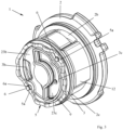
- the figures 2 , 3 , 17 and 18 show pump inserts that can be inserted into a receiving housing, as in figure 1 shown.
- the pump in particular the pump insert 1, comprises a spring 5, which is shown here in various embodiments.
- the pump or the pump insert 1 can have a seal 9 , in particular an axial seal, arranged between an end wall 20c of a receiving housing 20 and a second housing part 3 .
- the seal 9 is shown partially combined with the spring 5 in various embodiments.
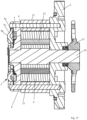
- the pump or the pump insert 1 has a rotor 4 which is connected in a torque-proof manner to a pump shaft 10 via a shaft-hub connection 30 .
- the rotor 4 has recesses, in particular slot-shaped recesses, which serve as guides.
- a conveying element 13, in particular a vane, is assigned to each recess.
- the vane 13 is at its recess radially or away from the axis of rotation D of the rotor 4 and to the axis of rotation D of the Rotor 4 can be moved out, in particular with a single translational degree of freedom, moved back and forth, such. e.g figure 20 is recognizable.
- the wings 13 are rotated with the rotor 4.
- the pump 1 has an annular housing part, namely a cam ring 12 .
- the cam ring 12 is sandwiched between a first housing part 2 and a second housing part 3 and is non-rotatable with respect to the first and second housing parts 2, 3.
- the second and third housing part 2, 3 is limited, can also be referred to as the pump chamber 26.
- the rotor 4 and the vanes 13 are arranged in the pump chamber 26 .
- a delivery cell 29 is formed between adjacent vanes 13, the volume of which changes depending on the rotational position of the rotor 4 about its axis of rotation D. Since the pump has a plurality of vanes 13, it also has a corresponding number of delivery cells 29. Several delivery cells 29 are located in each of the delivery chambers 27, 28.
- the cam ring 12 and/or the vanes 13 can be magnetized, so that the vanes 13 bear against the inner peripheral surface of the cam ring 12 due to magnetic force, in particular even when the rotor 4 is not rotating. This allows pressure to build up early when starting or cold starting, i. H. when the pump shaft 10 starts rotating.
- the vanes 13 can rotate outwards, i. H. are pressed away from the axis of rotation of the rotor 4 against the inner peripheral surface of the cam ring 12.
- the wings 13 or each of the wings 13 forms a third sealing gap with the inner peripheral surface of the cam ring 12 .
- the inner peripheral surface of the cam ring 12 has a contour which causes the vanes 13 to extend at least once for a full revolution of the rotor 4 (Increase in volume of the delivery cell 29) and retract once (decrease in volume of the delivery cell 29).
- the pump shown in the example is double-stroke, ie with two delivery chambers 27, 28, the vanes 13 extending once per delivery chamber 27, 28 and retracting once when they are moved through the delivery chamber 27, 28 by rotation of the rotor 4.
- the blades 13 are caused to extend, retract, extend and retract again for one full revolution of the rotor 4, or in other words extend twice and retract twice.
- a delivery cell 29 is formed between adjacent wings 13, the volume of which increases or decreases as a result of the extension and retraction of the wings 13 delimiting this delivery cell 29, namely depending on the contour of the inner peripheral surface of the cam ring 12.
- the pump insert 1 comprises at least one positioning element 6, in the example shown two positioned elements 6.
- the positioning elements 6 are pins or pin-shaped.
- the positioning element 6 is firmly anchored in the first housing part 2 .
- the first housing part 2 has a blind hole 2a, into which the pin-shaped positioning element 6 is pressed with a first end.
- the pin-shaped positioning element 6 positions the second housing part 3 and the cam ring 12 with respect to their angular positions about the axis of rotation D relative to the first housing part 2.
- the second housing part 3 and the cam ring 12 have recesses, openings, bores or elongated holes, preferably with a radial extension. through which the positioning element 6 extends.
- the cam ring 12 has a bore 12a for the first positioning element 6 and a further bore 12a for the second positioning element 6 for this purpose.
- the second housing part 3 has a through hole through which the positioning element 6 extends.
- the pin-shaped second end of the positioning element 6 protrudes beyond the end face that points away from the pump chamber 26 .
- This protruding portion of the positioning element 6 has a recess, such as. B. an annular groove 6a, or at least a part thereof, which extends over the circumference of the positioning element 6.
- a securing element or fastening element 5a of the spring 5 is arranged in the recess 6a and is fastened in particular in a non-positive and/or positive manner to the positioning element 6 or in the annular groove 6a.
- the fastening element 5a prevents the first housing part 2, the second housing part 3 and the cam ring 12 from falling apart axially, or in other words, the second housing part 3 and the cam ring 12 from being pulled off the positioning element 6. This also makes the spring 5 captive on the pump insert 1, in particular the positioning elements 6 attached.
- the pump shaft 10 is rotatably mounted on the first and second housing part 2, 3, in particular by means of a slide bearing in each case.
- this can be done without the support in the second housing part 3 or only with the Storage in the first housing part 2 is sufficient, in particular when the pump insert 1 is double-stroke, ie has two pumping chambers 27, 28 which are opposite one another, for example in relation to the axis of rotation D.
- the forces caused by the pressures in the pumping chambers 27, 28 transverse to the axis of rotation D can cancel each other out as a result.
- an external structure such as. B. formed an external toothing on the pump shaft 10, which is in a form-fitting engagement with a corresponding internal structure, in particular internal toothing of the rotor 4, to form a shaft-hub connection 30.
- the outer diameter of the outer structure of the pump shaft 10 is larger than the diameter of the section of the pump shaft 10 that is mounted in the first housing part 2 and/or in the second housing part 3 .
- the pump shaft 10 is axially fixed between the first and second housing parts 2, 3, i.
- the outer diameter of the sections of the first housing part 2 and the second housing part 3, which support the pump shaft 10 is smaller than the outer diameter of the outer structure of the pump shaft 10.
- the first housing part 2 has, on its front side facing away from the pump chamber 26 , an annular pocket in which a shaft seal 11 is arranged, which is fastened to the first housing part 2 in a rotationally fixed manner and forms a sealing gap with the pump shaft 10 .
- the shaft seal 11 seals off the pump chamber 26 from the outside.
- the end of the pump shaft 10 which is opposite the end which is arranged in the area of the spring 5 has an outer contour for a shaft-hub connection 30 with a drive wheel, in particular gear wheel 21, in particular a chain wheel.
- the gear 21 is non-rotatably seated on the pump shaft 10.
- the gear 21 can be driven by a chain, which in turn can be driven by z. B. a crankshaft or other shaft connected to z. B. may be connected to an engine of the vehicle is driven.
- the gear 21 has for its attachment to the pump shaft 10 z. B. has an internal thread with which it is screwed to an external thread of the pump shaft 10 against a shoulder of the pump shaft 10 .
- An anti-rotation lock seated on the shaft 10 secures the gear wheel 21 against unintentional loosening.
- the drive wheel 21 by means of a Joined or attached to the pump shaft 10 by interference fit or other types of connection.
- the pump insert 1 is in the examples shown in a z. B. cup-shaped receiving housing 20, such as. B. used a housing pot ( figure 1 ).
- the receiving housing 20 has a peripheral wall 20d which surrounds one of the pump inserts 1 shown here on the peripheral side. Furthermore, the receiving housing 20 has an end wall 20c which is monolithically connected to the peripheral wall 20d, the spring 5 being supported on the end wall 20c in particular axially, ie in the direction of the axis of rotation D.
- the pump insert 1 is between the end wall 20c and an axial securing element, such as. B. a screw, an axial locking ring or a cover so that the spring 5 is tensioned or remains, in particular is tensioned or remains under pressure.
- the axial securing element can bear against the first housing part 2 and/or can hold the first housing part 2 in a non-displaceable manner on the receiving housing 20 along or in the direction of the axis of rotation D.
- the seal 9 is arranged in a sealing groove or a sealing pocket of the second housing part 3 which annularly surrounds one end of the second outlet channel 3c, the bottom of the groove or the bottom of the pocket forming a sealing surface for the seal 9 .
- the wall the groove or pocket which annularly surrounds the seal is at a distance from the end wall 20c which is less than the height of the seal 9, in particular than the height of the first ring 9a, which will be described further below.
- a gap extrusion of the seal 9 is prevented by the first ring 9a, in particular its material, and/or the smaller gap width between wall and end wall 20c.
- a gap extrusion can also be avoided by a support structure in the seal 9 .
- the first and second housing parts 2, 3 and the cam ring 12 are sealed off from one another.
- the connection between the axial securing element and the first housing part 2 is made so strong that it can withstand the axial force on the axial securing element, as caused by the pressure in the pressure chambers 23b, 23c, i. H. is not resolved.
- the axial securing element is a housing cover which is fastened to the receiving housing 20 and on which the first housing part 2 is supported axially.
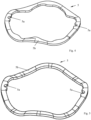
- a spring 5 z. B a suitably designed corrugated ring spring, a multi-corrugated spring washer, a hose or arc spring, a grooved ring spring, a metal O-ring or a metal C-ring in question. If the spring 5 is to be fastened to the positioning elements 6, the spring can have fastening elements 5a for fastening them to the positioning elements 6.
- the spring 5 On its circumference, the spring 5 has several, here two, fastening elements 5a in the form of recesses which are open towards the inner circumference and which can be arranged in the annular groove 6a of a positioning element 6 .
- the thickness of the flat material of the spring 5 is less than the groove width of the annular groove 6a.
- the spring 5 off figure 5 is so far identical to the spring 5 from figure 4 .
- the spring 5 off figure 4 additionally has several inwardly protruding protrusions on its inner circumference.
- the spring 5 off figure 6 essentially corresponds to the design figure 5 , wherein the spring structure 5b from figure 6 more waves than the embodiment figure 5 has, ie is more corrugated.
- the spring structure 5b has a positioning element 5e, which can engage in a corresponding recess in the second housing part 3 in order to fasten the spring 5 to the fastening elements 6 in the correct position.
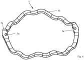
- FIG 7 shows an annular spring 5, which has several tubular sections 5f over its circumference, in this example two tubular sections 5f. Between adjacent tubular portions 5f there is arranged a fastener 5a and in particular a flat portion 5g in which the fastener 5a is formed.
- the fastening element 5a is a recess open towards the inner circumference of the ring.
- the thickness of the flat portion 5g is smaller than the groove width of the annular groove 6a of the positioning member 6.
- the flat portion 5g can be formed by compressing and plastically deforming a previously continuous tubular portion 5f. In the example shown there are two fasteners 5a and thus two flat portions 5g.
- the spring 5 has two tubular sections 5f, which are connected at their ends respectively via a flat section 5g, which is provided with a fastening element 5a.
- the embodiment off figure 8 shows a spring 5 identical to the spring from figure 7 is, with the exception of the configuration of the tubular portions 5f.
- the execution off figure 8 namely has C-shaped sections 5h instead of a tubular section 5f. Otherwise, execution will depend on it figure 7 referred.
- the C-shaped sections 5h each have a contour that is open in cross section, namely a slot that extends over the circumference, in particular the inner circumference of the ring-shaped spring structure.
- the springs 5 or spring structures 5b from the Figures 4 to 8 are preferably made of metal, in particular spring steel.
- the springs 5 can be coated or encapsulated, in particular with a plastic, such as. B. a polymer or elastomeric or thermoplastic material or z. B. with a paint.
- Polytetrafluoroethylene is particularly suitable, the core strength of which can be increased by inserted fibers, for example glass fibers, so that the axial seal can withstand considerable pressure.
- ethylene-tetrafluoroethylene copolymer ETFE
- Polyterephthalate is also well suited for the intended purpose, since it can be easily vulcanized with the sealing ring.
- Polyamides, with or without a glass fiber insert, are also suitable for the intended purpose.
- the second ring 9b is preferably made of a plastic, in particular an elastomeric or rubber-elastic material or elastomer, which is preferably readily vulcanizable, does not tear and is not highly sensitive to notches.
- a plastic in particular an elastomeric or rubber-elastic material or elastomer, which is preferably readily vulcanizable, does not tear and is not highly sensitive to notches.
- the listed materials and materials also apply in particular, but not only to the statements from the figures 10 , 11 , 15 and 16 , but can be used, for example, for all embodiments shown or described in the present application.
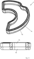
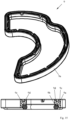
- the first ring 9a has a V-shaped groove over its circumference.
- a counterpart formed by the second ring and adapted to this shape of the groove is arranged in the groove and is connected, in particular vulcanized or glued, to the first ring 9a in the groove.
- figure 15 shows a first ring 9a, which has a step running around its annular circumference, in which the second ring 9b, which is designed as an O-ring, is accommodated.
- the second ring 9b is integrally connected to the first ring 9a.
- the second ring 9b is loosely inserted into the first ring 9a, in particular into the stepped shoulder.
- the front end of the seal which is opposite the front end formed by the second ring 9b, has at least one groove running around the annular circumference of the first ring 9a.
- the groove is bordered by a first circumferential, in particular inner groove wall 9c and a second circumferential, in particular outer groove wall 9d.
- the first groove wall 9c is continuous over the circumference and is supported on its sealing surface in a sealing manner, as a result of which the first pressure chamber 23b is sealed off from the second pressure chamber 23c.
- the second groove wall 9d is provided with a plurality of recesses over its circumference, which make the second groove wall 9d liquid-permeable, as a result of which only the first groove wall 9c is sealed.
- the second groove wall 9d serves to support the seal on the sealing surface so that the seal 9 does not tilt.
- the second groove wall 9d can be continuous over the circumference and the first groove wall 9c can be provided with the plurality of recesses, with the above-described being transferable to this embodiment.
- the second groove wall 9d can primarily serve for sealing and the first groove wall 9c primarily for support.
- FIG 16 shows a seal 9, which consists of only one ring, such as. B. from the material for the above first ring 9a or the above second ring 9b, depending according to the expected pressure difference between the first pressure chamber 23b and the second pressure chamber 23c.
- a front end of the seal is designed with a sealing lip, which has an inclined inner surface, which is inclined in such a way that internal pressure in the second pressure chamber 23c exerts a force on the sealing lip, which at least partially acts against the sealing surface of the second housing part 3 or the end wall 20c presses.
- On the inner circumference is a variety of z. B. arranged along the height of the seal 5 or in the direction of the axis of rotation D extended recesses z. B.
- sealing lip is open towards the inner circumference to ensure that the sealing lip, even if it is deformed in the assembled state of the pump insert 1 in the receiving housing 20, is subjected to pressure fluid from the second pressure chamber 23c in order to press it against its sealing surface, e.g second housing part 3 is formed to press.
- the face of the seal 9 opposite the sealing lip can be flat or even or as shown in figure 15 be designed.
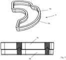
- figure 12 shows an annular seal 9, which has a first ring 9a made of the above-mentioned first material, alternatively made of metal, in particular steel, which is essentially completely coated or encapsulated over its surface with plastic, in particular the elastomeric or rubber-elastic or thermoplastic material, whereby a second ring 9b is formed.
- first ring 9a made of the above-mentioned first material, alternatively made of metal, in particular steel, which is essentially completely coated or encapsulated over its surface with plastic, in particular the elastomeric or rubber-elastic or thermoplastic material, whereby a second ring 9b is formed.
- FIG 13 shows an annular seal 9, which has a first ring 9a, which is designed as a ring-shaped circumferential tube.
- the ring 9a can e.g. B. as an alternative to the materials mentioned for the first ring 9a made of a metallic spring material, in particular spring steel.
- the ring-shaped circumferential tube 9a can have a closed wall or z. B. be wound from a helical spring.
- the first ring 9a is coated or encapsulated over its outer circumference with plastic, in particular the elastomeric or rubber-elastic or thermoplastic material, as a result of which a second ring 9b is formed which surrounds the first ring 9a.
- the pipe 9a out figure 13 can thus act as a spring and the coating or encapsulation 9b as a seal 9. The same applies mutatis mutandis to the execution figure 14 .
- the execution off figure 14 shows a first ring 9a, which is formed from a slotted tube or a C-shaped profile, which runs around a closed ring.
- the slot of the C-shaped profile or of the slotted tube 9a points inwards and consequently to the second pressure chamber.
- the first ring 9a is coated or encapsulated with plastic, in particular the elastomeric or rubber-elastic or thermoplastic material, over its outer circumference, resulting in a second ring 9b which at least partially surrounds the first ring 9a.
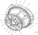
- the spring 5 off figure 19 has an annular spring structure 5b with a first spring structure ring 5k, which in particular extends concentrically around the axis of rotation D.
- the spring structure 5b is made of metal, in particular steel, which gives the spring 5 its essential spring property in the direction of the axis of rotation D.
- the ring-shaped spring structure 5b has a plurality of arms 5d projecting inwards from the first spring structure ring 5k and distributed over its circumference, the ends of which projecting inwards are freely projecting.
- the arms 5c each have a contact surface 5d with which they rest against the end wall 20c.
- the underside of the first spring structure ring 5k of the spring structure 5b bears against the second housing part 3 in the area which is arranged in axial alignment with the cam ring 12 in the direction of the axis of rotation D.
- the first spring structure ring 5k has two fastening elements 5a, which are designed as continuous recesses, such as e.g. B. holes or slots are formed.
- the bore or the elongated hole is surrounded at least over part of its circumference by a wall which has a thickness extending along or in the direction of the axis of rotation D that is smaller than the groove width of the annular groove 6a of the positioning element 6.
- the spring structure ring 5k can be elastically compressed or pushed apart along an imaginary connecting line between the two fastening elements 5a in order to enable it to be slipped onto the positioning elements 6 and, by releasing, a part of the wall to snap into place to allow in the annular groove 6a.
- the spring structure 5b has a second spring structure ring 5j, which annularly surrounds the second pressure chamber 23c. Furthermore, the spring structure 5b has a third spring structure ring 5i, which extends around the axis of rotation D and is arranged inside the first spring structure ring 5k, from which the arms 5d protrude.
- At least the second spring structure ring 5j, preferably and if present also the third spring structure ring 5i and optionally also the first spring structure ring 5k are coated or overmoulded with plastic, in particular the elastomeric or rubber-elastic or thermoplastic material, at least partially or completely, so that at least the in the direction of the Axis of rotation D pointing ends of the second ring, which includes the second spring structure ring 5j, and the third ring, which includes the third spring structure ring 5i, are formed with a surface made of plastic, in particular the elastomeric or rubber-elastic or thermoplastic material. Furthermore, the elastomeric or rubber-elastic or thermoplastic material separates the second pressure chamber 23c from the first pressure chamber 23b.
- the second ring with its encapsulation or coating can thus be defined as a seal 9 .
- the third ring with its coating or encapsulation seals the bore of the second housing part 3, in which a section of the pump shaft 10 is arranged, with respect to the first pressure chamber 23b and the second pressure chamber 23c.
- the encapsulation or coating of the third ring is supported on the second housing part 3 and on the opposite side on the housing wall 20c.
Abstract
Pumpe, umfassend ein Aufnahmegehäuse (20), welches einen topfförmigen Aufnahmeraum (25) mit einer Stirnwand (20c) und einer Umfangswand (20d) bildet, einen Pumpeneinsatz (1), der in dem Aufnahmeraum (25) angeordnet ist, wobei der Pumpeneinsatz (1) aufweist:- einen Rotor (4) und eine Pumpenwelle (10),- ein erstes Gehäuseteil (2) und ein zweites Gehäuseteil (3), zwischen denen der Rotor (4) um eine Drehachse (D) und relativ zu dem ersten und zweiten Gehäuseteil (2, 3) drehbar angeordnet ist, wobei die Pumpenwelle (10) verdrehfest mit dem Rotor (4) verbunden und in dem ersten Gehäuseteil (2) und in einer sackförmigen Ausnehmung des zweiten Gehäuseteils (3) drehbar gelagert ist,- einen Hubring (12), welcher den Rotor (4) umgibt und zwischen dem ersten Gehäuseteil (2) und dem zweiten Gehäuseteil (3) angeordnet ist,wobeizwischen dem Aufnahmegehäuse (20) und dem zweiten Gehäuseteil (3) eine zweite Dichtung (8), insbesondere ein Dichtring, angeordnet ist, welche einen ersten Druckraum (23b), der zwischen der Stirnwand (20c) und dem zweiten Gehäuseteil (3) gebildet ist, in Bezug auf einen Saugraum (24), der zwischen der Umfangswand (20d) und dem Hubring (12) gebildet ist, abdichtet undzwischen dem ersten Gehäuseteil (2) und dem Aufnahmegehäuse (20), insbesondere der Umfangswand (20d) des Aufnahmegehäuses (20), eine erste Dichtung (7), die beispielsweise die Abdichtung des Saugraums (24) nach außen hin oder zur Öffnung des Aufnahmegehäuses (20) hin bewirkt, angeordnet ist, wobei der Saugraum (24) zwischen der ersten Dichtung (7) und der zweiten Dichtung (8) gebildet ist, undzwischen dem zweiten Gehäuseteil (3) und der Stirnwand (20c) des Aufnahmegehäuses (20) ein Dichtelement (9) angeordnet ist, welches einen zweiten Druckraum (23c) ringförmig umgibt.Pump, comprising a receiving housing (20) which forms a pot-shaped receiving space (25) with an end wall (20c) and a peripheral wall (20d), a pump insert (1) which is arranged in the receiving space (25), the pump insert ( 1) comprises:- a rotor (4) and a pump shaft (10),- a first housing part (2) and a second housing part (3), between which the rotor (4) rotates about an axis of rotation (D) and relative to the first and the second housing part (2, 3) is rotatably arranged, the pump shaft (10) being connected to the rotor (4) in a rotationally fixed manner and being rotatably mounted in the first housing part (2) and in a sack-shaped recess in the second housing part (3), a cam ring (12), which surrounds the rotor (4) and is arranged between the first housing part (2) and the second housing part (3), wherein between the receiving housing (20) and the second housing part (3) a second seal (8) , in particular a sealing ring, is arranged, which has a first pressure space (23b) formed between the end wall (20c) and the second housing part (3) in relation to a suction space (24) formed between the peripheral wall (20d) and is formed on the cam ring (12), and between the first housing part (2) and the receiving housing (20), in particular the peripheral wall (20d) of the receiving housing (20), a first seal (7) which, for example, seals off the suction chamber (24 ) to the outside or to the opening of the receiving housing (20), the suction space (24) being formed between the first seal (7) and the second seal (8), and between the second housing part (3) and the A sealing element (9) is arranged on the end wall (20c) of the receiving housing (20) and surrounds a second pressure chamber (23c) in the form of a ring.
Description
Die Erfindung betrifft eine Pumpe, insbesondere eine Verdrängerpumpe für eine Flüssigkeit, wie z. B. Öl. Die Pumpe kann z. B. als Flügelzellenpumpe oder Drehschieberpumpe, Innen- oder Außenzahnradpumpe, Pendelschieberpumpe oder Rollenzellenpumpe ausgestaltet sein. Die Pumpe eignet sich insbesondere für den Einbau in ein Fahrzeug, wie z. B. ein Kraftfahrzeug und/oder zur Versorgung eines Verbrauchers in einem Kraftfahrzeug. Der Verbraucher kann z. B. ein Verbrennungsmotor, ein Getriebe, wie z. B. ein Lenkgetriebe oder Automatikgetriebe sein. Ein erster Aspekt betrifft die Abstützung einer Feder, die zwischen einem Aufnahmegehäuse und einem in dem Aufnahmegehäuse eingesetzten Pumpeneinsatz wirkt. Ein zweiter Aspekt betrifft die Kombination einer Dichtung mit einer zwischen dem Aufnahmegehäuse und dem Pumpeneinsatz wirkenden Feder. Ein dritter Aspekt betrifft die Abdichtung von Druckräumen einer mehrhubigen Pumpe zueinander. Jeder der genannten Aspekte kann aber muss nicht notwendigerweise mit einem oder mehreren der anderen genannten Aspekte oder deren Weiterbildungen kombiniert werden.The invention relates to a pump, in particular a positive displacement pump for a liquid, such as. e.g. oil. The pump can B. be designed as a vane pump or rotary vane pump, internal or external gear pump, pendulum vane pump or roller cell pump. The pump is particularly suitable for installation in a vehicle such. B. a motor vehicle and / or to supply a consumer in a motor vehicle. For example, the consumer can B. an internal combustion engine, a transmission such. B. be a steering gear or automatic transmission. A first aspect relates to the support of a spring which acts between a receiving housing and a pump insert inserted in the receiving housing. A second aspect relates to the combination of a seal with a spring acting between the receiving housing and the pump insert. A third aspect relates to the sealing off of the pressure chambers of a multi-stroke pump from one another. Each of the aspects mentioned can, but does not necessarily have to, be combined with one or more of the other aspects mentioned or their developments.
Aus der
Die
Dem ersten Aspekt liegt die Aufgabe zugrunde, eine durch die Federkraft bewirkte nachteilige Verformung des Pumpendeckels und/oder der Stirnwand des Aufnahmegehäuses möglichst zu vermeiden. Dem zweiten Aspekt liegt die Aufgabe zugrunde, die Montierbarkeit des Pumpeneinsatzes in das Aufnahmegehäuse zu erleichtern. Dem dritten Aspekt liegt die Aufgabe zugrunde, eine platzsparende Pumpe anzugeben, welche verschiedene Fluidkreisläufe mit Druckfluid versorgen kann.The first aspect is based on the task of avoiding, as far as possible, a disadvantageous deformation of the pump cover and/or the front wall of the receiving housing caused by the spring force. The second aspect is based on the task of facilitating the mountability of the pump insert in the receiving housing. The third aspect is based on the object of specifying a space-saving pump which can supply various fluid circuits with pressure fluid.
Die Erfindung geht von einer Pumpe, insbesondere Verdrängerpumpe, wie z. B. Flügelzellen- oder Drehschieberpumpe oder einer Zahnradpumpe oder einer Pendelschieberpumpe oder einer Rollenzellenpumpe aus. Die Pumpe umfasst ein Aufnahmegehäuse, welches einen topfförmigen Aufnahmeraum mit einer Stirnwand und einer Umfangswand bildet, und einen Pumpeneinsatz, der in dem Aufnahmeraum insbesondere als separat von dem Aufnahmegehäuse handhabbare Einheit angeordnet oder eingesetzt ist. Der Pumpeneinsatz kann sich an der Umfangswand des topfförmigen Aufnahmeraums abstützen oder zentrieren oder mit der Umfangswand mindestens einen über den Umfang umlaufenden Dichtspalt bilden. Der Pumpeneinsatz kann somit von der Umfangswand geführt werden.The invention relates to a pump, in particular positive displacement pump such. B. vane or rotary vane pump or a gear pump or a pendulum vane pump or a roller cell pump. The pump comprises a receiving housing, which forms a pot-shaped receiving space with an end wall and a peripheral wall, and a pump insert, which is arranged or used in the receiving space, in particular as a unit that can be handled separately from the receiving housing. The pump insert can be supported or centered on the peripheral wall of the pot-shaped receiving space or form at least one circumferential sealing gap with the peripheral wall. The pump insert can thus be guided by the peripheral wall.
Der Pumpeneinsatz umfasst ein Gehäuse, welches einen Pumpenraum einfasst. In dem Pumpenraum kann ein Rotor um eine Drehachse relativ zu dem Gehäuse drehbar angeordnet sein. Die Pumpe kann den Rotor und zumindest ein erstes Gehäuseteil, insbesondere einen ersten Gehäusedeckel und ein zweites Gehäuseteil, insbesondere einen zweiten Gehäusedeckel, zwischen denen der Rotor um eine Drehachse relativ zu dem ersten und zweiten Gehäuseteil drehbar angeordnet ist, umfassen. Der Rotor kann unmittelbar oder mittelbar drehmomentübertragend mit einer Pumpenwelle verbunden oder verbindbar sein, wie z. B. über eine Welle-Nabe-Verbindung. Wenn die Pumpenwelle relativ zu dem ersten und zweiten Gehäuseteil gedreht wird, dreht sich der Rotor mit. Der Rotor weist Ausnehmungen, insbesondere Führungen, wie z. B. schlitzförmige Ausnehmungen oder Führungen, auf, in denen Förderelemente, wie z. B. Flügel, Schieber oder Rollen, radial zur Drehachse bewegbar, insbesondere verschiebbar aufgenommen sind. Die Förderelemente sind so von dem Rotor aufgenommen oder gelagert, dass sie sich mit dem Rotor um seine Drehachse mitdrehen. Insbesondere ist jedes der Förderelemente in seiner Führung mit einem einzigen translatorischen Freiheitsgrad verschiebbar gelagert.The pump insert includes a housing which encloses a pump chamber. A rotor can be arranged in the pump chamber so that it can rotate about an axis of rotation relative to the housing. The pump can include the rotor and at least a first housing part, in particular a first housing cover, and a second housing part, in particular a second housing cover, between which the rotor is arranged such that it can rotate about an axis of rotation relative to the first and second housing parts. The rotor can be directly or indirectly connected or connectable in a torque-transmitting manner to a pump shaft, e.g. B. via a shaft-hub connection. When the pump shaft is rotated relative to the first and second housing parts, the rotor rotates with it. The rotor has recesses, in particular guides such. B. slot-shaped recesses or guides, in which conveying elements such. B. wings, slides or rollers, radially movable to the axis of rotation, in particular are slidably received. The conveying elements are accommodated or mounted by the rotor in such a way that they rotate with the rotor about its axis of rotation. In particular, each of the conveyor elements is slidably mounted in its guide with a single translatory degree of freedom.
Die Pumpenwelle kann sich durch das Gehäuse erstrecken und um die Drehachse drehbar an dem Gehäuse gelagert sein, wie z. B. mit einem ersten Abschnitt an dem ersten Gehäuseteil und mit einem zweiten Abschnitt an dem zweiten Gehäuseteil. Zwischen dem ersten Abschnitt und dem zweiten Abschnitt der Pumpenwelle kann eine Außenstruktur für die Welle-Nabe-Verbindung gebildet sein. Der Rotor und die Pumpenwelle können mittels einer z. B. geradverzahnten Welle-Nabe-Verbindung verdrehfest verbunden sein. Die Welle-Nabe-Verbindung weist eine Innenverzahnung mit mehreren Zähnen und eine in die Innenverzahnung eingreifende Außenverzahnung mit mehreren Zähnen auf.The pump shaft may extend through the housing and be rotatably mounted on the housing about the axis of rotation, such as. B. with a first portion on the first housing part and with a second portion on the second housing part. An outer structure for the shaft-hub connection can be formed between the first section and the second section of the pump shaft. The rotor and the pump shaft can by means of a z. B. straight-toothed shaft-hub connection. The shaft-hub connection has an internal toothing with a plurality of teeth and an external toothing with a plurality of teeth which meshes with the internal toothing.
Zwischen dem ersten Gehäuseteil und dem zweiten Gehäuseteil kann ein drittes Gehäuseteil, nämlich ein Hubring, angeordnet sein. Der Hubring umgibt den Rotor über seinen Umfang. Der Hubring kann ein von dem ersten und zweiten Gehäuseteil separates Teil sein. Alternativ kann der Hubring ein von dem ersten Gehäuseteil gebildeter Abschnitt des ersten Gehäuseteils oder ein von dem zweiten Gehäuseteil gebildeter Abschnitt des zweiten Gehäuseteils sein. Das erste Gehäuseteil oder das zweite Gehäuseteil oder beide können den Rotor und insbesondere seine Förderelemente umgeben, wie z. B. ringförmig umgeben, wenn der Hubring Teil des ersten oder zweiten Gehäuseteils ist.A third housing part, namely a cam ring, can be arranged between the first housing part and the second housing part. The cam ring surrounds the rotor over its circumference. The cam ring may be a separate part from the first and second housing parts. Alternatively, the cam ring can be a section of the first housing part formed by the first housing part or a section of the second housing part formed by the second housing part. The first housing part or the second housing part or both can Surround rotor and in particular its conveying elements such. B. ring-shaped when the cam ring is part of the first or second housing part.
Das erste Gehäuseteil, das zweite Gehäuseteil und der Hubring fassen ein und begrenzen eine Pumpenkammer, in der der Rotor und die Förderelemente angeordnet sind. Radial zwischen dem Hubring und dem Rotor, der zwischen dem ersten und dem zweiten Gehäuseteil drehbar eingefasst ist, ist mindestens eine Förderkammer gebildet, wie z. B. eine erste Förderkammer und eine zweite Förderkammer bei einer doppelhubigen Pumpe.The first housing part, the second housing part and the cam ring enclose and delimit a pump chamber in which the rotor and the conveying elements are arranged. At least one pumping chamber is formed radially between the cam ring and the rotor, which is rotatably enclosed between the first and second housing parts, such as e.g. B. a first pumping chamber and a second pumping chamber in a double-stroke pump.
Zwischen benachbarten Förderelementen ist jeweils eine Förderzelle gebildet, die umfangsseitig von einer Innenumfangsfläche des Hubrings und in Richtung der Drehachse von dem ersten Gehäuseteil auf einer Seite und von dem zweiten Gehäuseteil auf der anderen Seite begrenzt wird und deren Volumen sich in Abhängigkeit von der Drehposition des Rotors um seine Drehachse verändert. Die Pumpe weist eine Vielzahl von Förderelementen und somit eine insbesondere gleiche Vielzahl von Förderzellen auf, die zwischen den Förderelementen gebildet sind.A delivery cell is formed between adjacent delivery elements, which is delimited on the circumference by an inner peripheral surface of the cam ring and in the direction of the axis of rotation by the first housing part on one side and by the second housing part on the other side and whose volume changes depending on the rotational position of the rotor changed around its axis of rotation. The pump has a multiplicity of conveying elements and thus, in particular, an identical multiplicity of conveying cells which are formed between the conveying elements.
Der Innenumfang des Hubrings weist eine Kontur auf, an welcher die Förderelemente bei einer Drehung des Rotors entlanggleiten. Die Kontur ist insbesondere so ausgebildet, dass sich die Volumina der aufgrund der Drehung des Rotors durch die Förderkammer bewegenden Förderzellen zunächst vergrößern und anschließend verkleinern. Bei einer vollständigen Umdrehung des Rotors werden die Förderelemente zumindest einmal von der Drehachse weg und zur Drehachse hin bewegt. Die Pumpe kann z. B. doppelhubig, d. h. mit einer ersten Förderkammer und einer zweiten Förderkammer ausgebildet sein, die von den Förderelementen bzw. den Förderzellen bei einer vollen Umdrehung jeweils einmal durchlaufen werden. D. h., dass die Förderelemente bei einer vollständigen Umdrehung abwechselnd zweimal von der Drehachse weg und zweimal zu der Drehachse hinbewegt werden. Während einer Drehung des Rotors findet zunächst eine Volumenvergrößerung einer Förderzelle und anschließend eine Volumenverkleinerung dieser Förderzelle statt.The inner circumference of the cam ring has a contour along which the conveying elements slide when the rotor rotates. The contour is designed in particular in such a way that the volumes of the delivery cells moving through the delivery chamber due to the rotation of the rotor initially increase and then decrease. During a complete revolution of the rotor, the conveying elements are moved away from the axis of rotation and toward the axis of rotation at least once. The pump can B. double stroke, d. H. be formed with a first pumping chamber and a second pumping chamber, which are traversed by the pumping elements or the pumping cells once in a full revolution. This means that the conveying elements are alternately moved twice away from the axis of rotation and twice towards the axis of rotation during a complete revolution. During a rotation of the rotor, the volume of a delivery cell first increases and then the volume of this delivery cell decreases.
Die Pumpe oder der Pumpeneinsatz kann mindestens einen Einlasskanal aufweisen, der in den Bereich der Förderkammer mündet, in dem die Volumenvergrößerung der Förderzelle stattfindet, und mindestens einen Auslasskanal aufweisen, der in den Bereich der Förderkammer mündet, in dem die Volumenverkleinerung dieser Förderzelle stattfindet.The pump or the pump insert can have at least one inlet channel, which opens into the area of the pumping chamber in which the increase in volume of the pumping cell takes place, and have at least one outlet channel, which opens into the area of the pumping chamber in which the reduction in volume of this pumping cell takes place.
Durch die Volumenvergrößerung der Förderzelle wirkt der mindestens eine Einlasskanal als Saugkanal. Durch die Volumenverkleinerung wirkt der mindestens eine Auslasskanal als Druckkanal. Eine einhubige Pumpe kann z. B. einen Einlasskanal und einen Auslasskanal aufweisen. Eine doppelhubige Pumpe kann z. B. einen gemeinsamen Einlasskanal für die erste und zweite Förderkammer und einen ersten Auslasskanal für die erste Förderkammer und einen davon separaten zweiten Auslasskanal für die zweite Förderkammer aufweisen. In einer Alternative kann der Pumpeneinsatz einen ersten Einlasskanal für die erste Förderkammer und einen davon separaten zweiten Einlasskanal für die zweite Förderkammer und einen ersten Auslasskanal für die erste Förderkammer und einen davon separaten zweiten Auslasskanal für die zweite Förderkammer oder einen gemeinsamen Auslasskanal für die erste und zweite Förderkammer aufweisen. Mit dem über die erste Förderkammer geförderten Fluid können z. B. andere oder die gleichen Verbraucher versorgt werden als mit dem über die zweite Förderkammer geförderten Fluid. Bei der Versorgung unterschiedlicher Verbraucher können unterschiedliche Druckniveaus zwischen dem ersten Auslasskanal und dem zweiten Auslasskanal bzw. zwischen dem ersten Druckraum, in den der erste Auslasskanal mündet, und dem zweiten Druckraum, in den der zweite Auslasskanal mündet, entstehen. Die Förderelemente und/oder der Rotor bilden mit dem ersten Gehäuseteil und dem zweiten Gehäuseteil jeweils einen Druckspalt. Der mindestens eine Einlasskanal kann mit einem Fluidvorratsbehälter, wie z. B. einem Ölbehälter verbunden sein oder werden, insbesondere in Fluidverbindung stehen. Z. B. kann der mindestens eine Saugkanal in einen Saugraum münden, der z. B. zwischen dem Aufnahmegehäuse und dem Pumpeneinsatz gebildet sein kann, insbesondere zwischen der Umfangswand des Aufnahmegehäuses und dem Pumpeneinsatz, wie z. B. dem Hubring. Der mindestens eine Auslasskanal kann mit mindestens einem Fluidverbraucher verbunden sein, wie z. B. mit einem Getriebe in Fluidverbindung stehen.Due to the increase in volume of the delivery cell, the at least one inlet channel acts as a suction channel. Due to the reduction in volume, the at least one outlet channel acts as a pressure channel. A single-stroke pump can e.g. B. have an inlet port and an outlet port. A double-stroke pump can e.g. B. have a common inlet channel for the first and second pumping chamber and a first outlet channel for the first pumping chamber and a separate second outlet channel for the second pumping chamber. In an alternative, the pump insert can have a first inlet channel for the first delivery chamber and a second inlet channel separate therefrom for the second delivery chamber and a first outlet channel for the first delivery chamber and a second outlet channel separate therefrom for the second delivery chamber or a common outlet channel for the first and second Have pumping chamber. With the funded via the first pumping chamber fluid z. B. other or the same consumers are supplied as with the funded via the second pumping chamber fluid. When supplying different consumers, different pressure levels can arise between the first outlet channel and the second outlet channel or between the first pressure chamber into which the first outlet channel opens and the second pressure chamber into which the second outlet channel opens. The conveying elements and/or the rotor each form a pressure gap with the first housing part and the second housing part. The at least one inlet channel can be connected to a fluid reservoir, such as a B. be connected to an oil tank or are, in particular in fluid communication. For example, the at least one suction channel can open into a suction space which, for example, B. can be formed between the receiving housing and the pump insert, in particular between the peripheral wall of the receiving housing and the pump insert, such as. B. the lifting ring. The at least one outlet channel can be connected to at least one fluid consumer, such as. B. are in fluid communication with a transmission.
Der Pumpeneinsatz kann mindestens ein Positionierelement aufweisen, welches das zweite Gehäuseteil bezüglich seiner Winkelposition um die Drehachse relativ zu dem ersten Gehäuseteil positioniert. Das mindestens eine Positionierelement kann von dem ersten Gehäuseteil gebildet sein, insbesondere einstückig oder monolithisch. Alternativ kann das mindestens eine Positionierelement als ein von dem ersten Gehäuseteil separates Teil gebildet sein, welches in dem ersten Gehäuseteil verankert ist. Z. B. kann das Positionierelement in das erste Gehäuseteil eingeschraubt oder eingepresst, d. h. formschlüssig und/oder kraftschlüssig verankert sein. Alternativ oder zusätzlich kann das mindestens eine Positionierelement in dem ersten Gehäuseteil stoffschlüssig verankert, wie z. B. verklebt, verlötet oder verschweißt sein. Das erste Gehäuseteil kann je Positionierelement eine Bohrung aufweisen, in der ein Ende des Positionierelements eingefügt und dadurch in den ersten Gehäuseteil verankert ist. Z. B. können zwei, drei, vier oder noch mehr Positionierelemente vorgesehen sein.The pump insert can have at least one positioning element, which positions the second housing part with respect to its angular position about the axis of rotation relative to the first housing part. The at least one positioning element can be formed by the first housing part, in particular in one piece or monolithically. Alternatively, the at least one positioning element can be formed as a part that is separate from the first housing part and is anchored in the first housing part. For example, the positioning element can be screwed or pressed into the first housing part, ie anchored in a positive and/or non-positive manner. Alternatively or additionally, the at least one Positioning anchored in the first housing part materially such. B. glued, soldered or welded. The first housing part can have a bore for each positioning element, in which one end of the positioning element is inserted and thereby anchored in the first housing part. For example, two, three, four or even more positioning elements can be provided.
Das mindestens eine Positionierelement kann insbesondere stiftförmig oder zylindrisch sein. Z. B. kann das dem verankerten Ende gegenüberliegende Ende des Positionierelements den gleichen Außendurchmesser wie das verankerte Ende aufweisen.The at least one positioning element can in particular be pin-shaped or cylindrical. For example, the end of the positioning member opposite the anchored end may have the same outside diameter as the anchored end.
Das zweite Gehäuseteil und insbesondere auch der Hubring können um die Drehachse verdrehgesichert an dem mindestens einen Positionierelement gelagert sein. Das mindestens eine Positionierelement kann sich durch eine je Positionierelement vorgesehene Ausnehmung des zweiten Gehäuseteils, wie z. B. durch eine Bohrung oder Durchgangsbohrung, erstrecken. Das mindestens eine Positionierelement kann sich z. B. durch eine Ausnehmung des Hubrings erstrecken, die z. B. als Bohrung, Langloch oder dergleichen ausgebildet sein kann.The second housing part and in particular also the cam ring can be mounted on the at least one positioning element, secured against rotation about the axis of rotation. The at least one positioning element can be formed by a recess provided for each positioning element in the second housing part, e.g. B. through a hole or through hole extend. The at least one positioning element can, for. B. extend through a recess of the cam ring, the z. B. can be formed as a bore, slot or the like.
Insbesondere kann das mindestens eine Positionierelement mit seinem Ende, das dem im ersten Gehäuseteil verankerten Ende gegenüberliegt, aus dem zweiten Gehäuseteil ragen, insbesondere von der Stirnseite des zweiten Gehäuseteils ragen, welche der Stirnseite gegenüberliegt, die zu dem Rotor weist oder welche zu der Stirnwand des Aufnahmegehäuses weist.In particular, the end of the at least one positioning element which is opposite the end anchored in the first housing part can protrude from the second housing part, in particular from the end face of the second housing part which is opposite the end face which points towards the rotor or which faces the end wall of the Recording housing has.
Die Pumpe oder der Pumpeneinsatz kann eine Feder aufweisen, die sich z. B. an dem zweiten Gehäuseteil und an dem Boden oder der Stirnwand des Aufnahmegehäuses abstützt. Das Aufnahmegehäuse kann wie gesagt z. B. topfförmig sein. Die Umfangswand des Aufnahmegehäuses kann sich um die Drehachse des Rotors erstrecken. Die Stirnwand ist stirnseitig der Umfangswand angeordnet, so dass das Aufnahmegehäuse topfförmig ist. Die zwischen der Stirnwand und den Pumpeneinsatz gespannte Feder trachtet, den Pumpeneinsatz, insbesondere das zweite Gehäuseteil von der Stirnwand des Aufnahmegehäuses wegzudrücken.The pump or the pump insert can have a spring which, for. B. on the second housing part and on the bottom or the end wall of the receiving housing. The receiving housing can as I said z. B. be pot-shaped. The peripheral wall of the receiving case may extend around the axis of rotation of the rotor. The front wall is arranged on the front side of the peripheral wall, so that the receiving housing is pot-shaped. The spring tensioned between the end wall and the pump insert tries to push the pump insert, in particular the second housing part, away from the end wall of the receiving housing.
Ein Herausfallen des Pumpeneinsatzes aus dem Aufnahmegehäuse wird z. B. durch einen Deckel oder ein Axialsicherungselement verhindert, wobei die beim Einsetzen gespannte Feder den Pumpeneinsatz, insbesondere das erste Gehäuseteil gegen das Axialsicherungselement oder den Deckel drückt, wobei das Axialsicherungselement oder der Deckel verhindert, dass sich die Feder entspannt. Das Axialsicherungselement kann z. B. ringförmig sein und in einer Ringnut, die am vorzugsweise zylindrischen Umfang des Aufnahmegehäuses gebildet wird, eingesetzt sein. Das Axialsicherungselement kann von einem Deckel gebildet sein, der die Öffnung zumindest teilweise oder vollständig verschließt.Falling out of the pump insert from the receiving housing is z. B. prevented by a cover or an axial securing element, with the strained during insertion The spring presses the pump insert, in particular the first housing part, against the axial securing element or the cover, with the axial securing element or the cover preventing the spring from relaxing. The axial securing element can, for. B. be annular and in an annular groove which is formed on the preferably cylindrical periphery of the receiving housing, be used. The axial securing element can be formed by a cover which at least partially or completely closes the opening.
Die zwischen dem Pumpeneinsatz und der Stirnwand gespannte Feder übt eine von der Stirnwand wegweisende und insbesondere entlang, d.h. in Richtung der Drehachse des Rotors wirkende Kraft auf das zweite Gehäuseteil aus, welches dadurch gegen den Hubring gedrückt wird, wobei der Hubring gegen das erste Gehäuseteil gedrückt wird. Das Widerlager hierfür bildet der Deckel oder das Axialsicherungselement. Durch die Federkraft wird der Hubring in Bezug auf das erste und zweite Gehäuseteil axial abgedichtet, wodurch sich beim Anlaufen der Pumpe Druck in der Förderkammer oder den Förderkammern aufbauen kann.The spring tensioned between the pump insert and the end wall exerts a force pointing away from the end wall and acting in particular along, i.e. in the direction of the axis of rotation of the rotor, on the second housing part, which is thereby pressed against the cam ring, with the cam ring being pressed against the first housing part becomes. The cover or the axial securing element forms the abutment for this. The spring force seals the cam ring axially in relation to the first and second housing parts, as a result of which pressure can build up in the pumping chamber or pumping chambers when the pump starts up.
Die Feder kann insbesondere verliersicher an dem Pumpeneinsatz befestigt sein, insbesondere an dem mindestens einen Positionierelement oder dem zweiten Gehäuseteil. Die Feder kann z. B. mit dem Positionierelement oder dem zweiten Gehäuseteil formschlüssig, insbesondere verschnappt oder kraftschlüssig verbunden sein, so dass die Feder an dem mindestens einen Positionierelement oder dem zweiten Gehäuseteil gehalten wird und sich vorzugsweise an dem zweiten Gehäuseteil abstützt oder abstützen kann. Bevorzugt ist, dass die Feder um die Drehachse verdrehgesichert, insbesondere form- oder/und kraftschlüssig, an dem mindestens einen Positionierelement oder dem zweiten Gehäuseteil befestigt ist. Die Feder kann mindestens ein Befestigungselement aufweisen oder bilden, insbesondere am oder im Bereich eines Abstützabschnitts, mit dem sich die Feder an dem zweiten Gehäuseteil oder an einem Teil, welches sich mittelbar oder unmittelbar an dem zweiten Gehäuseteil abstützt, abstützt. Z. B. kann das mindestens eine Befestigungselement als Abstützabschnitt dienen oder je Abstützabschnitt ein Befestigungselement vorgesehen sein. Mittels des Befestigungselements kann die Feder an dem mindestens einen Positionierelement oder dem zweiten Gehäuseteil befestigbar oder befestigt sein. Das Befestigungselement, welches z. B. für eine formschlüssige Verbindung mit dem ihm zugeordneten Positionierelement ausgestaltet ist, kann mit dem Positionierelement verschnappt sein.The spring can in particular be captively attached to the pump insert, in particular to the at least one positioning element or the second housing part. The spring can B. with the positioning element or the second housing part positively, in particular snapped or non-positively connected, so that the spring is held on the at least one positioning element or the second housing part and is preferably supported or can be supported on the second housing part. It is preferred that the spring is secured against rotation about the axis of rotation, in particular in a positive and/or non-positive manner, on the at least one positioning element or the second housing part. The spring can have or form at least one fastening element, in particular on or in the area of a support section with which the spring is supported on the second housing part or on a part which is supported directly or indirectly on the second housing part. For example, the at least one fastening element can serve as a support section or one fastening element can be provided for each support section. The spring can be fastened or fastened to the at least one positioning element or the second housing part by means of the fastening element. The fastener which z. B. is designed for a positive connection with the positioning element assigned to it, can be snapped to the positioning element.
Das mindestens eine Positionierelement kann eine Ausnehmung, wie z. B. eine Ringnut über seinen Umfang aufweisen, in welche das mindestens eine Befestigungselement der Feder eingreift. Eine derartige Ringnut kann als Einstich ausgebildet sein. Z. B. kann das mindestens eine Befestigungselement sicherungsscheibenförmig oder seegerringförmig ausgestalt sein, ähnlich wie Sicherungsscheiben für Wellen nach DIN 6799 oder Sicherungsringe für Wellen nach DIN 471, insbesondere mit dem Unterschied, dass sie von der Feder gebildet werden, nämlich an dem Abstützabschnitt angeformt sein können.The at least one positioning element can have a recess, e.g. B. have an annular groove over its circumference, in which engages the at least one fastener of the spring. Such an annular groove can be designed as a recess. For example, the at least one fastening element can be in the form of a lock washer or circlip, similar to lock washers for shafts according to DIN 6799 or circlips for shafts according to DIN 471, in particular with the difference that they are formed by the spring, namely can be molded onto the support section.
In alternativen Ausführungsformen kann das Sicherungselement, insbesondere die z. B. nach DIN 6799 ausgestaltete Sicherungsscheibe oder der nach DIN 471 ausgestaltete Seegerring tatsächlich eine Scheibe oder ein Ring sein, d. h. nicht an der Feder angeformt sein und z. B. nur dazu dienen, dass das zweite Gehäuseteil axial nicht von dem Positionierelement abziehbar ist. In dieser Ausführungsform kann die Feder an dem zweiten Gehäuseteil oder an dem Sicherungselement befestigt oder zwischen dem Sicherungselement und dem zweiten Gehäuseteil eingefasst sein, wobei das Befestigungselement der Feder auf das Positionierelement aufgesteckt sein kann. In alternativen Ausführungsformen kann das Positionierelement z. B. mit einem Kopf ausgestaltet sein, wobei das zweite Gehäuseteil zwischen dem ersten Gehäuseteil und dem Kopf eingefasst ist, so dass verhindert wird, dass das zweite Gehäuseteil von dem ersten Gehäuseteil bzw. von dem Positionierelement abgezogen werden kann. In diesen Ausführungsformen kann die Feder an dem zweiten Gehäuseteil oder an dem Kopf befestigt oder zwischen dem Kopf und dem zweiten Gehäuseteil eingefasst sein, wobei das Befestigungselement der Feder auf das Positionierelement aufgesteckt sein kann.In alternative embodiments, the fuse element, in particular the z. B. designed according to DIN 6799 lock washer or configured according to DIN 471 Seeger ring actually be a disc or a ring, d. H. not be formed on the spring and z. B. only serve to ensure that the second housing part cannot be pulled off axially from the positioning element. In this embodiment, the spring can be fastened to the second housing part or to the securing element or can be sandwiched between the securing element and the second housing part, wherein the fastening element of the spring can be plugged onto the positioning element. In alternative embodiments, the positioning element z. B. be configured with a head, wherein the second housing part is enclosed between the first housing part and the head, so that it is prevented that the second housing part can be removed from the first housing part or from the positioning element. In these embodiments, the spring may be attached to the second body part or to the head, or sandwiched between the head and the second body part, wherein the fastening element of the spring may be clipped onto the positioning element.
In weiteren Ausführungsformen kann die Ausnehmung eine sich über den Umfang des zylindrischen oder stiftförmigen Positionierelements erstreckende Ringnut sein, welche eine entlang der Längsachse des Positionierelements erstreckte Breite aufweist, die so bemessen ist, dass das Befestigungselement der Feder mit einem Spiel entlang der Längsachse in der Ringnut aufgenommen ist. Hierdurch kann sichergestellt werden, dass sich der Abstützabschnitt oder der Befestigungsabschnitt der Feder an dem zweiten Gehäuseteil und nicht an einer Nutflanke der Ringnut abstützt.In further embodiments, the recess can be an annular groove that extends over the circumference of the cylindrical or pin-shaped positioning element and has a width that extends along the longitudinal axis of the positioning element, which width is dimensioned such that the fastening element of the spring is in the annular groove with play along the longitudinal axis is recorded. In this way it can be ensured that the supporting section or the fastening section of the spring is supported on the second housing part and not on a groove flank of the annular groove.
In Ausführungsformen, in denen die Feder am zweiten Gehäuseteil befestigt ist, kann das zweite Gehäuseteil an einer Innenumfangsfläche oder einer Außenumfangsfläche eine um die Drehachse des Rotors zumindest teilweise oder vollständig umlaufende Nut aufweisen, die nach innen oder nach außen hin offen ist, wobei die Feder, d.h. ein oder mehrere Abschnitte der Feder in der Nut an dem zweiten Gehäuseteil befestigt, insbesondere von der Nut eingefasst ist. Die Nutbreite ist etwas größer als die Dicke der Abschnitte der Feder, die in der Nut zur Befestigung angeordnet werden. Zum Beispiel kann die Feder zum Einfügen in die Nut seitlich elastisch zusammengedrückt werden, wobei die Feder in unmittelbarer Nähe der Nut platziert und anschließend losgelassen wird. Durch die Elastizität der Feder nimmt diese wieder ihre ursprüngliche Form ein, wodurch die Feder bzw. Abschnitte davon in die Nut einrasten und die Feder verliersicher an dem zweiten Gehäuseteil befestigen. Die Feder kann zum Beispiel im entspannten Zustand eine ovale Form oder Abragungen, welche die besagten Abschnitte bilden, aufweisen, wobei die umlaufende Nut oder Ringnut sich kreisförmig um die Drehachse erstreckt.In embodiments in which the spring is attached to the second housing part, the second housing part on an inner peripheral surface or an outer peripheral surface around the Axis of rotation of the rotor at least partially or completely circumferential groove which is open inwards or outwards, wherein the tongue, ie one or more sections of the tongue is fastened in the groove on the second housing part, in particular bordered by the groove. The groove width is slightly larger than the thickness of the portions of the tongue that are placed in the groove for attachment. For example, the tongue may be laterally elastically compressed for insertion into the groove, the tongue being placed in close proximity to the groove and then released. Due to the elasticity of the tongue, it resumes its original shape, as a result of which the tongue or sections thereof snap into the groove and fasten the tongue captively to the second housing part. The spring can, for example, have an oval shape in the relaxed state, or projections forming said sections, with the circumferential groove or annular groove extending in a circle around the axis of rotation.
Die Pumpe kann eine Pumpenwelle aufweisen, welche verdrehfest mit dem Rotor verbunden und um die Drehachse drehbar ist. Die Pumpenwelle kann zumindest in dem ersten Gehäuseteil drehbar gelagert sein. Zusätzlich kann die Pumpenwelle in dem zweiten Gehäuseteil drehbar gelagert sein, insbesondere in einer sackförmigen Ausnehmung oder in einer durchgehenden Ausnehmung, insbesondere Bohrung, durch das zweite Gehäuseteil. Die sackförmige Ausnehmung hat den Vorteil, dass die Pumpenkammer zu der von der Pumpenkammer wegweisenden Stirnseite des zweiten Gehäuseteils abgedichtet ist. Die durchgehende Ausnehmung hat den Vorteil, dass sie einfach zu Fertigen ist und eine höhere Stabilität gewährleistet. Das oder die Lager können Gleit- oder Wälzlager sein.The pump can have a pump shaft which is connected to the rotor in a rotationally fixed manner and can be rotated about the axis of rotation. The pump shaft can be rotatably mounted at least in the first housing part. In addition, the pump shaft can be rotatably mounted in the second housing part, in particular in a sack-shaped recess or in a continuous recess, in particular a bore, through the second housing part. The bag-shaped recess has the advantage that the pump chamber is sealed off from the end face of the second housing part pointing away from the pump chamber. The continuous recess has the advantage that it is easy to manufacture and ensures greater stability. The bearing or bearings can be plain or roller bearings.
Die Pumpenwelle kann eine Struktur, insbesondere eine Außenverzahnung für eine Welle-Nabe-Verbindung mit dem Rotor aufweisen. Der Durchmesser der Struktur kann größer als der Innendurchmesser des ersten Gehäuseteils und/oder des zweiten Gehäuseteils oder der Lager sein. Die Struktur ist somit zwischen dem ersten Gehäuseteil und dem zweiten Gehäuseteil entlang, d.h. in Richtung der Drehachse eingefasst. Dadurch wird bewirkt, dass die Welle nicht aus dem fertig montierten Pumpeneinsatz herausgezogen werden kann.The pump shaft can have a structure, in particular external teeth, for a shaft-hub connection to the rotor. The diameter of the structure may be larger than the inner diameter of the first housing part and/or the second housing part or the bearings. The structure is thus sandwiched between the first housing part and the second housing part along, i.e. in the direction of the axis of rotation. This means that the shaft cannot be pulled out of the fully assembled pump insert.
Insbesondere das erste Gehäuseteil, das zweite Gehäuseteil, der Hubring, der Rotor, die Förderelemente, die Positionierelemente, die Feder und die Pumpenwelle können im Wesentlichen den Pumpeneinsatz, der als Einheit handhabbar ist, bilden. Dadurch, dass die Feder an dem mindestens einen Positionierelement befestigt wird, kann ein Auseinanderfallen des Pumpeneinsatzes vermieden werden. Die Befestigungsabschnitte der Feder und/oder die von der Feder separaten Sicherungselemente bewirken eine axiale Wellensicherung, so dass der Pumpeneinsatz nicht auseinanderfällt.In particular, the first housing part, the second housing part, the cam ring, the rotor, the conveying elements, the positioning elements, the spring and the pump shaft can essentially form the pump insert, which can be handled as a unit. Because the spring is attached to the at least one positioning element, it can fall apart of pump use can be avoided. The fastening sections of the spring and/or the securing elements which are separate from the spring effect an axial securing of the shaft, so that the pump insert does not fall apart.
Durch die einfache Handhabung des Pumpeneinsatzes kann dieser in das Aufnahmegehäuse, das z. B. von einem Getriebegehäuse für ein Kraftfahrzeug gebildet sein kann, aufgenommen werden bzw. in das Aufnahmegehäuse eingesetzt werden, z. B. über eine der Stirnwand gegenüberliegende Öffnung des Aufnahmegehäuses.The easy handling of the pump insert this can in the receiving housing z. B. can be formed by a transmission housing for a motor vehicle, are included or used in the receiving housing, z. B. via one of the end wall opposite opening of the receiving housing.
In weiteren Ausführungsformen kann zwischen dem zweiten Gehäuseteil und dem Aufnahmegehäuse, insbesondere Umfangswand, eine (zweite) Dichtung, insbesondere ein Dichtring angeordnet sein, welche einen Druckraum, der im Wesentlichen zwischen der Stirnwand und dem zweiten Gehäuseteil gebildet ist, in Bezug auf einen Saugraum, der zwischen der Umfangswand und dem ersten Gehäuseteil und/oder dem Hubring gebildet ist, abdichtet. Beispielsweise kann der Druckraum mittels des mindestens einen Auslasskanals mit der mindestens einen Förderkammer verbunden sein.In further embodiments, a (second) seal, in particular a sealing ring, can be arranged between the second housing part and the receiving housing, in particular the peripheral wall, which seals a pressure space, which is essentially formed between the end wall and the second housing part, with respect to a suction space, which is formed between the peripheral wall and the first housing part and / or the cam ring seals. For example, the pressure chamber can be connected to the at least one delivery chamber by means of the at least one outlet channel.
Zwischen dem ersten Gehäuseteil und dem Aufnahmegehäuse, insbesondere der Umfangswand, kann eine (erste) Dichtung, insbesondere ein Dichtring angeordnet sein, wobei der Saugraum zwischen der ersten und zweiten Dichtung angeordnet ist. Die erste Dichtung kann die Abdichtung des Saugraums nach außen oder zur Öffnung des Aufnahmegehäuses hin bewirken.A (first) seal, in particular a sealing ring, can be arranged between the first housing part and the receiving housing, in particular the peripheral wall, with the suction space being arranged between the first and second seal. The first seal can cause the suction chamber to be sealed off from the outside or from the opening of the receiving housing.
Dadurch, dass der mindestens eine Druckraum zwischen der Stirnwand und dem zweiten Gehäuseteil angeordnet ist, wirkt das zweite Gehäuseteil wie ein Kolben, der bei Druckerhöhung im Druckraum die Kraft entlang oder in Richtung der Drehachse auf das Axialsicherungselement oder den Deckel erhöht und somit auch die Teile des Pumpeneinsatzes, insbesondere das erste Gehäuseteil, das zweite Gehäuseteil und den Hubring, dichtend aneinanderdrückt und zwar mit einer steigenden Kraft bei steigendem Förderdruck und insbesondere zusätzlich zu der Kraft der vorgespannten Feder.Because the at least one pressure chamber is arranged between the end wall and the second housing part, the second housing part acts like a piston which, when the pressure in the pressure chamber increases, increases the force along or in the direction of the axis of rotation on the axial securing element or the cover and thus also the parts of the pump insert, in particular the first housing part, the second housing part and the cam ring, sealingly presses against one another with an increasing force as the delivery pressure increases and in particular in addition to the force of the prestressed spring.
Nach dem ersten Aspekt stützt sich die zwischen dem Aufnahmegehäuse und dem zweiten Gehäuse federnd angeordnete, insbesondere gespannte Feder zum zweiten Gehäuseteil hin im Wesentlichen in einem Bereich ab, der in Richtung der Drehachse des Rotors in einer axialen Flucht mit dem Hubring angeordnet ist, und dadurch, d. h. durch die Abstützung in Flucht mit dem Hubring, das zweite Gehäuseteil gegen den Hubring drückt. In einer Flucht bedeutet, in einer gedachten axialen Verlängerung der Wand des Hubrings entlang oder in Richtung der Drehachse. Bei der
Insbesondere kann die Feder eine Federstruktur aus Metall, insbesondere aus Stahl oder Federstahl aufweisen, wobei die Federstruktur aus Metall der Feder ihre wesentliche Federeigenschaft entlang oder in Richtung der Drehachse verleiht. Dies ist so zu verstehen, dass die Feder z. B. mit einem anderen Material beschichtet oder umspritzt sein kann, welches ebenfalls eine Federeigenschaft aufweist, wenngleich diese gegenüber der Federstruktur aus Metall vernachlässigbar ist.In particular, the spring can have a spring structure made of metal, in particular steel or spring steel, the spring structure made of metal giving the spring its essential spring property along or in the direction of the axis of rotation. This is to be understood that the spring z. B. can be coated or encapsulated with another material, which also has a spring property, although this is negligible compared to the spring structure made of metal.
Die Feder kann sich mittelbar oder unmittelbar an dem zweiten Gehäuseteil abstützen. Beispielsweise kann ein Zwischenteil zwischen dem zweiten Gehäuseteil und der Feder angeordnet sein, wobei sich die Feder an dem Zwischenteil abstützt. Insbesondere kann sich das Zwischenteil an dem zweiten Gehäuseteil abstützen, vorzugsweise ebenfalls in einem Bereich, der in Richtung der Drehachse in einer axialen Flucht mit dem Hubring angeordnet ist.The spring can be supported directly or indirectly on the second housing part. For example, an intermediate part can be arranged between the second housing part and the spring, with the spring being supported on the intermediate part. In particular, the intermediate part can be supported on the second housing part, preferably likewise in a region which is arranged in axial alignment with the cam ring in the direction of the axis of rotation.
Das Zwischenteil kann z. B. eine sogenannte Kaltstartplatte oder eine plattenförmige Struktur, wie z. B. ein perforiertes (Metall-) Blech oder eine Siebstruktur, aufweisen oder sein. Das Zwischenteil kann z. B. zwischen der Feder und dem zweiten Gehäuseteil eingefasst oder angeordnet sein und/oder an dem mindestens einen Positionierelement gehalten oder befestigt sein, wie z. B. je Positionierelement, an dem es befestigt ist, eine Ausnehmung oder Bohrung aufweisen, durch welche sich das betreffende Positionierelement erstreckt. Das Zwischenteil kann mindestens einen Bereich mit der siebförmigen Struktur oder mindestens einen perforierten Bereich aufweisen, wie z. B. einen einzigen, zwei oder noch mehr solche Bereiche. Das Zwischenteil ist insbesondere so angeordnet, dass der mindestens eine Bereich von der aus der mindestens einen Förderkammer geförderten Flüssigkeit durchflossen wird. Durch den - wenngleich auch z.B. geringen - Strömungswiderstand, der durch den mindestens einen Bereich beim Durchströmen verursacht wird, steigt der Druck anströmungsseitig, d. h., auf der Seite des Zwischenteils, welche von der Flüssigkeit aus der mindestens einen Förderkammer angeströmt wird.The intermediate part can, for. B. a so-called cold start plate or a plate-shaped structure such. B. a perforated (metal) sheet or a screen structure, have or be. The intermediate part can, for. B. bordered or arranged between the spring and the second housing part and / or held or attached to the at least one positioning element be, such as B. each positioning element to which it is attached, have a recess or bore through which the positioning element in question extends. The intermediate part can have at least one area with the sieve-like structure or at least one perforated area, e.g. B. a single, two or more such areas. The intermediate part is arranged in particular in such a way that the liquid conveyed from the at least one delivery chamber flows through the at least one region. Due to the - albeit eg low - flow resistance caused by the at least one area during flow, the pressure increases on the inflow side, ie on the side of the intermediate part on which the liquid from the at least one delivery chamber flows.
Anströmungsseitig des Zwischenteils weist der Pumpeneinsatz, insbesondere das zweite Gehäuseteil, mindestens einen Verbindungskanal auf, der die Unterflügelkammern, d. h. die Kammern, die in den Schlitzen gebildet sind, in denen die Flügel geführt sind, und sich radial zwischen einen Ende des jeweiligen Flügels und dem Grund des jeweiligen Schlitzes erstrecken, mit dem aus der mindestens einen Förderkammer geförderten Flüssigkeit versorgt. Der durch den durchflossenen Bereich des Zwischenteils erzeugte Staudruck bewirkt ein schnelleres Ausfahren der Flügel beim Kaltstart und somit generell einen schnelleren Druckaufbau durch die Pumpe. Das Zwischenteil und/oder die Feder, an der sich das Zwischenteil beispielsweise nachgiebig abstützen kann, kann alternativ oder zusätzlich zu der siebförmigen oder perforierten Struktur so flexibel nachgiebig gestaltet sein, dass das Zwischenteil beim Erreichen eines Grenzdrucks zumindest teilweise von dem zweiten Gehäuseteil abhebt, wodurch Flüssigkeit aus der Förderkammer durch einen dadurch gebildeten Spalt zwischen Zwischenteil und zweitem Gehäuseteil fließen kann.On the inflow side of the intermediate part, the pump insert, in particular the second housing part, has at least one connecting channel which connects the underwing chambers, i. H. the chambers, which are formed in the slots in which the vanes are guided and extend radially between an end of the respective vane and the bottom of the respective slot, are supplied with the liquid conveyed from the at least one conveying chamber. The dynamic pressure generated by the area of the intermediate part through which flow occurs causes the wings to be extended more quickly during a cold start and thus generally causes the pump to build up pressure more quickly. As an alternative or in addition to the sieve-shaped or perforated structure, the intermediate part and/or the spring, on which the intermediate part can be resiliently supported, can be designed so flexibly that the intermediate part lifts off the second housing part at least partially when a limit pressure is reached, as a result Liquid can flow from the pumping chamber through a gap formed thereby between the intermediate part and the second housing part.
Z. B. kann sich die Feder, insbesondere mit ihrem zum Aufnahmegehäuse hin bzw. zur Stirnwand weisenden Ende, im Wesentlichen in einem Bereich an dem Aufnahmegehäuse, insbesondere an der Stirnwand, abstützen, der in Richtung der Drehachse in einer axialen Flucht mit dem Hubring angeordnet ist. Ein Vorteil hierbei ist, dass eine Verformung der Stirnwand durch die Federkraft vermieden kann. Ein weiterer Vorteil ist, dass der Querschnitt, den die Feder insbesondere ringförmig umgibt, einen verhältnismäßig großen Durchmesser aufweist, insbesondere in etwa zumindest den Innendurchmesser oder den kleinsten Innendurchmesser des Hubrings. Hierdurch wird vorteilhaft erreicht, dass der von der Feder umgebene Querschnitt relativ groß ist und somit die Möglichkeit bietet, eine insbesondere ringförmige Dichtung, insbesondere Axialdichtung zwischen dem zweiten Gehäuseteil und der Stirnwand des Aufnahmegehäuses dichtend anzuordnen, um z. B. einen zweiten Druckraum gegenüber einem ersten Druckraum abzudichten. Demnach kann zwischen dem zweiten Gehäuseteil und der Stirnwand des Aufnahmegehäuses ein Dichtelement angeordnet sein, welches den Druckraum insbesondere ringförmig umgibt. Insbesondere kann die Feder ringförmig sein und einen Druckraum, insbesondere einen ersten Druckraum, der über den vom zweiten Gehäuseteil gebildeten Auslasskanal, insbesondere den ersten Auslasskanal, mit der Förderkammer, insbesondere der ersten Förderkammer, verbunden ist, zumindest teilweise umgeben. Insbesondere kann die Feder in dem ersten Druckraum angeordnet sein.For example, the spring, in particular with its end pointing towards the receiving housing or towards the end wall, can be supported essentially in a region on the receiving housing, in particular on the end wall, which is arranged in axial alignment with the cam ring in the direction of the axis of rotation. An advantage here is that deformation of the end wall by the spring force can be avoided. A further advantage is that the cross-section, which the spring surrounds in particular in the form of a ring, has a relatively large diameter, in particular approximately at least the inner diameter or the smallest inner diameter of the cam ring. This advantageously ensures that the cross-section surrounded by the spring is relatively large and thus offers the possibility of a in particular annular seal, in particular axial seal between the second housing part and the end wall of the receiving housing to be arranged in a sealing manner, e.g. B. seal a second pressure chamber from a first pressure chamber. Accordingly, a sealing element can be arranged between the second housing part and the end wall of the receiving housing, which in particular surrounds the pressure chamber in a ring shape. In particular, the spring can be ring-shaped and at least partially surround a pressure chamber, in particular a first pressure chamber, which is connected to the delivery chamber, in particular the first delivery chamber, via the outlet channel formed by the second housing part, in particular the first outlet channel. In particular, the spring can be arranged in the first pressure chamber.
Insbesondere kann die Dichtung, die hierin auch als Dichtelement bezeichnet wird, den zweiten Druckraum ringförmig umgeben, wobei der zwischen der Stirnwand des Aufnahmegehäuses und dem zweiten Gehäuseteil gebildete erste Druckraum mittels des Dichtelements zum zweiten Druckraum hin abgedichtet wird. Wie bereits erwähnt, kann der erste Druckraum über einen ersten Zuführzweig mit anderen Fluidverbrauchern verbunden sein als der zweite Druckraum, der über einen zweiten Zuführzweig, der separat von dem ersten Zuführzweig ist, mit Fluidverbrauchern verbunden ist. Alternativ ist es möglich, einen oder mehrere gemeinsame Fluidverbraucher über separate Zuführzweige, nämlich den ersten Zuführzweig und den zweiten Zuführzweig mit Fluid aus der ersten Druckkammer und der zweiten Druckkammer zu versorgen.In particular, the seal, which is also referred to herein as a sealing element, can surround the second pressure chamber in a ring shape, with the first pressure chamber formed between the end wall of the receiving housing and the second housing part being sealed off from the second pressure chamber by means of the sealing element. As already mentioned, the first pressure chamber can be connected to other fluid consumers via a first supply branch than the second pressure chamber, which is connected to fluid consumers via a second supply branch that is separate from the first supply branch. Alternatively, it is possible to supply one or more common fluid consumers with fluid from the first pressure chamber and the second pressure chamber via separate supply branches, namely the first supply branch and the second supply branch.
Die zwischen der Stirnwand und dem zweiten Gehäuseteil angeordnete Feder kann z. B. eine Wellringfeder, eine multigewellte Federscheibe, eine Schlauch- oder Bogenfeder, eine Nutringfeder, ein (Metall-)C-Ring oder ein (Metall-)O-Ring sein.The spring arranged between the end wall and the second housing part can e.g. B. a corrugated ring spring, a multi-corrugated spring washer, a hose or bow spring, a U-ring spring, a (metal) C-ring or a (metal) O-ring.
Eine multigewellte Federscheibe kann aufweisen oder bestehen aus einer Federstruktur aus Metall, insbesondere Stahl, wobei die Federstruktur aus einem Flach- oder Rundmaterial gebildet ist, welches einen insbesondere geschlossenen Ring bildet. Die Feder ist zumindest im unbelasteten Zustand über die Umfangsrichtung des Rings gewellt, d. h. wellenförmig oder mit mehreren Wellen, insbesondere mit mehreren Wellenbergen und Wellentälern ausgestaltet. Die Wellenhöhe erstreckt sich entlang oder in Richtung der Drehachse oder im Wesentlichen senkrecht oder normal auf die Ebene, welche durch die ringförmige Federstruktur aufgespannt wird. Die multigewellte Feder hat den Vorteil, dass sie sehr platzsparend eingesetzt werden kann.A multi-corrugated spring washer can have or consist of a spring structure made of metal, in particular steel, the spring structure being formed from a flat or round material, which forms a closed ring in particular. At least in the unloaded state, the spring is wavy over the circumferential direction of the ring, ie designed wavy or with several waves, in particular with several wave crests and wave troughs. The wave height extends along or towards the axis of rotation or substantially perpendicular or normal to the plane passing through the annular Spring structure is stretched. The multi-corrugated spring has the advantage that it can be used in a very space-saving manner.
Eine Wellfeder kann aufweisen oder bestehen aus einer aus einer Flach- oder Rundmaterial gebildeten Federstruktur, welche sich wendelförmig um eine Federlängsachse entlang einer Umfangsrichtung windet, wobei die Federstruktur in Umfangsrichtung gewellt ist oder mehrere Wellen, d. h. mehrere Wellenberge und Wellentäler aufweist. Die Federstruktur kann sich teilweise, vollständig oder mehrfach um die Federlängsachse winden, insbesondere in etwa gewellt wendelförmig. Benachbarte Windungen können mit ihren Wellenbergen und Wellentälern aneinanderstoßen oder miteinander befestigt sein. D. h., dass eine Windung mit ihrem Wellenberg an dem Wellental der nächstfolgenden Windung anliegt. Die Federstruktur kann eine Anfangswindung und/oder eine Endwindung aufweisen, wobei die Anfangswindung und/oder die Endwindung sich im Wesentlichen eben um die Federlängsachse erstrecken. Mit der Anfangswindung und/oder der Endwindung kann sich die Feder an der Stirnwand und/oder mittelbar oder unmittelbar dem zweiten Gehäuseteil abstützen. Durch die Anfangswindung und die Endwindung wird ein besseres Anliegen, d. h. eine flächigere Verteilung der Federkraft an den Teilen, an denen sich die Feder abstützt, bewirkt. Die Federlängsachse ist parallel oder liegt auf der Drehachse. Z. B. kann die Anfangswindung das Befestigungselement zur Befestigung an dem Positionierelement aufweisen.A corrugated spring can have or consist of a spring structure formed from a flat or round material, which winds helically around a longitudinal axis of the spring along a circumferential direction, the spring structure being corrugated in the circumferential direction or having a plurality of waves, i. H. has several crests and troughs. The spring structure can wind partially, completely or multiple times around the longitudinal axis of the spring, in particular in an approximately wavy, helical manner. Adjacent turns may crest and trough abut or may be fastened together. This means that the wave crest of a winding rests against the trough of the next winding. The spring structure can have an initial coil and/or an end coil, with the initial coil and/or the end coil extending substantially planarly around the longitudinal axis of the spring. With the initial turn and/or the end turn, the spring can be supported on the end wall and/or directly or indirectly on the second housing part. Through the initial coil and the final coil, a better fit, i.e. H. causes the spring force to be distributed over a larger area on the parts on which the spring is supported. The longitudinal axis of the spring is parallel or lies on the axis of rotation. For example, the initial turn may include the fastener for attachment to the positioning member.
Ein (Metall-)C-Ring oder ein (Metall-)O-Ring ist ringförmig. Die Federstruktur erstreckt sich zumindest abschnittsweise über den Umfang der Federlängsachse. Die Federlängsachse ist senkrecht oder steht normal auf die Fläche, die der Ring aufspannt. Die Federlängsachse ist im Wesentlichen parallel zu oder liegt auf der Drehachse des Rotors. Der Ring kann über seinen Umfang eben oder im Wesentlichen nicht gewellt sein. Die Federstruktur ist beim (Metall-)C-Ring im Querschnitt, der quer zur Umfangsrichtung ist, C-förmig, d. h. mit einer offenen Kontur, und beim (Metall-)O-Ring O-förmig, d. h. mit einer geschlossenen Kontur. Zwischen benachbarten Abschnitten, die eine C- oder O-ringförmige Federstruktur aufweisen, kann jeweils ein Befestigungselement zur Befestigung an dem Positionierelement gebildet sein. Die hierin genannten Federn können mehrere Befestigungselemente für mehrere Positionierelemente aufweisen.A (metal) C-ring or a (metal) O-ring is ring-shaped. The spring structure extends at least in sections over the circumference of the longitudinal axis of the spring. The longitudinal axis of the spring is vertical or is normal to the surface spanned by the ring. The longitudinal axis of the spring is essentially parallel to or lies on the axis of rotation of the rotor. The ring may be flat or substantially uncorrugated about its circumference. In the case of the (metal) C-ring, the spring structure is C-shaped in cross-section which is transverse to the circumferential direction, ie with an open contour, and in the case of the (metal) O-ring it is O-shaped, ie with a closed contour. A fastening element for fastening to the positioning element can be formed in each case between adjacent sections which have a C- or O-ring-shaped spring structure. The springs referred to herein may have multiple fasteners for multiple positioning members.
In einem zweiten Aspekt der Erfindung ist zwischen der Stirnwand und dem zweiten Gehäuseteil ein ringförmiges Dichtelement (Dichtung oder Axialdichtung) angeordnet, insbesondere das allgemein oder/und zum ersten Aspekt beschriebene Dichtelement, welches einen zwischen der Stirnwand und dem zweiten Gehäuseteil gebildeten Druckraum, insbesondere den zweiten Druckraum, einfasst, wobei der Druckraum über einen Auslasskanal mit einer zwischen dem Rotor und dem Hubring gebildeten Förderkammer verbunden ist. Die Feder weist eine Federstruktur aus Metall, insbesondere Federstahl, auf, welche der Feder ihre wesentliche Federeigenschaft verleiht, wobei an der Federstruktur das ringförmige Dichtelement befestigt, insbesondere verliersicher befestigt ist. Somit können die Feder und das Dichtelement eine Einheit oder integrale Einheit bilden, die als Einheit handhabbar ist. Z. B. kann beim Befestigen der Feder an dem zweiten Gehäuseteil oder dem mindestens einem Positionierelement das Dichtelement ebenfalls an der für das Dichtelement vorgesehenen Stelle an den zweiten Gehäuseteil angeordnet werden. Der Vorteil hierbei ist, dass die Feder und das Dichtelement mit einem Arbeitsschritt an dem Pumpeneinsatz befestigt werden können. Ferner wird vorteilhaft erreicht, dass das Dichtelement beim Einsetzen des Pumpeneinsatzes in das Aufnahmegehäuse fixiert ist und nicht verrutschen oder herausfallen kann. Somit wird die Montage des Pumpeneinsatzes in das Aufnahmegehäuse erleichtert. Das Dichtelement kann an dem Federelement z. B. durch Um- oder Anspritzen des Dichtelements an die Feder oder die Federstruktur befestigt werden. Alternativ kann die als Dichtelement bezeichnete Dichtung an der Federstruktur formschlüssig befestigt sein, wie z. B. durch Aufstecken, oder kraftschlüssig, wie z. B. durch Anklemmen.In a second aspect of the invention, an annular sealing element (seal or axial seal) is arranged between the end wall and the second housing part, in particular the sealing element described in general and/or for the first aspect, which forms a pressure chamber between the end wall and the second housing part, in particular the second pressure chamber, wherein the pressure chamber is connected via an outlet channel to a pumping chamber formed between the rotor and the cam ring. The spring has a spring structure made of metal, in particular spring steel, which gives the spring its essential spring property, the annular sealing element being fastened to the spring structure, in particular being fastened captively. Thus, the spring and the sealing element can form a unit or an integral unit that can be handled as a unit. For example, when attaching the spring to the second housing part or the at least one positioning element, the sealing element can also be arranged at the point provided for the sealing element on the second housing part. The advantage here is that the spring and the sealing element can be attached to the pump insert in one work step. Furthermore, it is advantageously achieved that the sealing element is fixed when the pump insert is inserted into the receiving housing and cannot slip or fall out. This makes it easier to fit the pump insert into the receiving housing. The sealing element can on the spring element z. B. be attached to the spring or the spring structure by molding or molding of the sealing element. Alternatively, the seal referred to as the sealing element can be attached to the spring structure in a form-fitting manner, e.g. B. by plugging, or non-positively, such as. B. by clamping.
Die Federstruktur kann z. B. einen zusätzlichen ringförmigen Abschnitt aufweisen, der Teil des Dichtelements ist und mit einem dichtenden Material, wie z. B. einem Polymer oder Elastomer umspritzt oder beschichtet ist. Der zusätzliche ringförmige Abschnitt wirkt als Stützstruktur, der einem Herausextrudieren oder einer Spaltextrusion des Dichtmaterials des Dichtelements aufgrund des Druckunterschieds zwischen dem ersten Druckraum und dem zweiten Druckraum entgegenwirkt.The spring structure can, for. B. have an additional annular portion which is part of the sealing element and with a sealing material such. B. a polymer or elastomer is molded or coated. The additional ring-shaped section acts as a support structure, which counteracts an extrusion out or a gap extrusion of the sealing material of the sealing element due to the pressure difference between the first pressure chamber and the second pressure chamber.
Die Federstruktur kann einen weiteren ringförmigen Abschnitt aufweisen, der ebenfalls mit dem dichtenden Material umspritzt oder beschichtet ist. Dieser weitere zusätzliche ringförmige Abschnitt kann die Drehachse des Rotors ringförmig umgeben, insbesondere die Pumpenwelle, wenn diese sich durch das zweite Gehäuseteil erstreckt, um den ersten Druckraum und/oder den zweiten Druckraum in Bezug auf die Pumpenwelle abzudichten. Die Dichtung oder das Dichtelement, welche den zweiten Druckraum umgibt, ist vorzugsweise exzentrisch zu der Drehachse des Rotors angeordnet, insbesondere in einem Bereich zwischen der ringförmigen Feder, welche den ersten Druckraum zumindest teilweise umgibt, und der Pumpenwelle oder einem Bereich, der in Richtung der Drehachse in einer axialen Flucht mit der Pumpenwelle angeordnet ist.The spring structure can have a further annular section, which is also overmoulded or coated with the sealing material. This further additional annular section can annularly surround the axis of rotation of the rotor, in particular the pump shaft if it extends through the second housing part, in order to seal off the first pressure chamber and/or the second pressure chamber with respect to the pump shaft. The seal or the sealing element, which surrounds the second pressure chamber, is preferably arranged eccentrically to the axis of rotation of the rotor, in particular in an area between the annular spring, which at least partially surrounds the first pressure chamber, and the pump shaft or an area that extends in the direction of the Axis of rotation is arranged in an axial alignment with the pump shaft.
In einem dritten Aspekt ist zwischen der Stirnwand und dem zweiten Gehäuseteil ein erster Druckraum und ein zweiter Druckraum gebildet, wie weiter oben bereits beschrieben wurde. Zwischen der Stirnwand und dem zweiten Gehäuseteil ist ein ringförmiges Dichtelement, wie bereits beschrieben wurde, angeordnet, welches den zweiten Druckraum einfasst und in Bezug auf den ersten Druckraum abdichtet. Der erste Druckraum ist über einen ersten Auslasskanal mit einer zwischen dem Rotor und dem Hubring gebildeten ersten Förderkammer und der zweite Druckraum ist über einen zweiten Auslasskanal mit einer zwischen dem Rotor und dem Hubring gebildeten zweiten Förderkammer verbunden. Hierdurch lassen sich, wie oben beschrieben, unterschiedliche oder gemeinsame Verbraucher über separate Zuführzweige mit Fluid versorgen, wobei sich in den ersten und zweiten Druckräumen unterschiedliche Drücke ausbilden können.In a third aspect, a first pressure chamber and a second pressure chamber are formed between the end wall and the second housing part, as has already been described above. An annular sealing element, as already described, is arranged between the end wall and the second housing part, which encloses the second pressure chamber and seals it off with respect to the first pressure chamber. The first pressure chamber is connected via a first outlet channel to a first pumping chamber formed between the rotor and the cam ring, and the second pressure chamber is connected via a second outlet channel to a second pumping chamber formed between the rotor and the cam ring. In this way, as described above, different or common consumers can be supplied with fluid via separate supply branches, with different pressures being able to develop in the first and second pressure chambers.
Die Erfindung wurde anhand mehrerer Beispiele und Ausführungen, insbesondere auch Aspekte beschrieben. Die Weiterbildungen eines Aspekts können auch die anderen Aspekte weiterbilden, ohne jedoch notwendigerweise von dem Kerngedanken des anderen Aspekts Gebrauch machen zu müssen. Besonders bevorzugte Ausführungen der Erfindung werden anhand von Figuren beschrieben. Die dabei offenbarten Merkmale bilden den Gegenstand der Erfindung einzeln und in jeglicher Merkmalskombination vorteilhaft weiter. Es zeigen:
Figur 1- einen Ausschnitt einer Schnittdarstellung durch eine Drehachse eines Rotors, wobei ein Pumpeneinsatz in ein Aufnahmegehäuse eingesetzt dargestellt ist,
Figur 2- eine Schnittansicht des Pumpeneinsatzes aus
Figur 1 durch die Drehachse, Figur 3- eine perspektivische Ansicht des Pumpeneinsatzes aus
Figur 2 , Figuren 4 und 5- Ausführungsformen für eine Feder für die Pumpenbaugruppe,
Figur 6- eine weitere Ausführungsform einer Feder für die Pumpenbaugruppe,
Figur 7- eine Ausführungsform einer Feder für die Pumpenbaugruppe mit einem O-ringförmigen Querschnitt,
Figur 8- eine Ausführungsform einer Feder für die Pumpenbaugruppe mit einem C-ringförmigen Querschnitt,
Figur 9- eine Ausführungsform einer Dichtung, die zwischen Pumpenbaugruppe und Aufnahmegehäuse angeordnet ist,
Figur 10- eine weitere Ausführungsform einer Dichtung,
Figur 11- noch eine weitere Ausführungsform einer Dichtung,
Figur 12- noch eine weitere Ausführungsform einer Dichtung,
Figur 13- noch eine weitere Ausführungsform einer Dichtung,
- Figur 14
- noch eine weitere Ausführungsform einer Dichtung,
- Figur 15
- noch eine weitere Ausführungsform einer Dichtung,
- Figur 16
- noch eine weitere Ausführungsform einer Dichtung,
- Figur 17
- ein Pumpeneinsatz im Schnitt entlang der Drehachse des Rotors, wobei der Pumpeneinsatz eine Feder, die mit einer Dichtung kombiniert ist, aufweist,
- Figur 18
- eine perspektivische Ansicht des Pumpeneinsatzes aus
Figur 17 , - Figur 19
- Darstellungen der mit der Dichtung kombinierten Feder und
Figur 20- ein exemplarischer Querschnitt durch einen Pumpeneinsatz im Bereich des Rotors.
- figure 1
- a detail of a sectional view through an axis of rotation of a rotor, wherein a pump insert is shown inserted into a receiving housing,
- figure 2
- a sectional view of the pump insert
figure 1 through the axis of rotation, - figure 3
- a perspective view of the pump insert
figure 2 , - Figures 4 and 5
- Embodiments for a spring for the pump assembly,
- figure 6
- another embodiment of a spring for the pump assembly,
- figure 7
- an embodiment of a spring for the pump assembly with an O-ring-shaped cross-section,
- figure 8
- an embodiment of a spring for the pump assembly with a C-ring shaped cross-section,
- figure 9
- an embodiment of a seal which is arranged between the pump assembly and the receiving housing,
- figure 10
- another embodiment of a seal,
- figure 11
- yet another embodiment of a seal,
- figure 12
- yet another embodiment of a seal,
- figure 13
- yet another embodiment of a seal,
- figure 14
- yet another embodiment of a seal,
- figure 15
- yet another embodiment of a seal,
- figure 16
- yet another embodiment of a seal,
- figure 17
- a pump cartridge in section along the axis of rotation of the rotor, the pump cartridge having a spring combined with a seal,
- figure 18
- a perspective view of the pump insert
figure 17 , - figure 19
- Representations of the spring combined with the seal and
- figure 20
- an exemplary cross section through a pump insert in the area of the rotor.
Die
Die Pumpe oder der Pumpeneinsatz 1 weist einen Rotor 4 auf, der über eine Welle-Nabe-Verbindung 30 mit einer Pumpenwelle 10 verdrehfest verbunden ist. Der Rotor 4 weist als Führung dienende, insbesondere schlitzförmige Ausnehmungen auf. Jeder Ausnehmung ist ein Förderelement 13, insbesondere ein Flügel, zugeordnet. Der Flügel 13 ist an seiner Ausnehmung radial oder von der Drehachse D des Rotors 4 weg und zur Drehachse D des Rotors 4 hin verschiebbar, insbesondere mit einem einzigen translatorischen Freiheitsgrad geführt, hin und her verschiebbar, wie z. B. aus
Wie am besten aus
Zwischen benachbarten Flügeln 13 ist jeweils eine Förderzelle 29 gebildet, deren Volumen sich in Abhängigkeit von der Drehposition des Rotors 4 um seine Drehachse D verändert. Da die Pumpe mehrere Flügel 13 aufweist, weist sie auch entsprechend mehrere Förderzellen 29 auf. In jeder der Förderkammern 27, 28 befinden sich mehrere Förderzellen 29.A
Die Flügel 13 und der Rotor 4 bilden mit dem ersten Gehäuseteil 2 einen ersten Dichtspalt und mit dem zweiten Gehäuseteil 3 einen zweiten Dichtspalt.The
Der Hubring 12 und/oder die Flügel 13 können magnetisiert sein, so dass die Flügel 13 aufgrund Magnetkraft an der Innenumfangsfläche des Hubrings 12 anliegen, insbesondere auch wenn sich der Rotor 4 nicht dreht. Dies erlaubt einen frühzeitigen Druckaufbau beim Start oder Kaltstart, d. h. wenn sich die Pumpenwelle 10 zu drehen beginnt. Alternativ oder zusätzlich können die Flügel 13 aufgrund der Fliehkraft bei der Drehung des Rotors nach Außen, d. h. von der Drehachse des Rotors 4 weg gegen die Innenumfangsfläche des Hubrings 12 gedrückt werden. Die Flügel 13 bzw. jeder der Flügel 13 bildet mit der Innenumfangsfläche des Hubrings 12 einen dritten Dichtspalt.The
Die Innenumfangsfläche des Hubrings 12 weist eine Kontur auf, die bewirkt, dass die Flügel 13 bei einer vollen Umdrehung des Rotors 4 zumindest einmal ausfahren (Volumenvergrößerung der Förderzelle 29) und einmal einfahren (Volumenverkleinerung der Förderzelle 29). Die in dem Beispiel gezeigte Pumpe ist doppelhubig, d. h. mit zwei Förderkammern 27, 28, wobei die Flügel 13 je Förderkammer 27, 28 einmal ausfahren und einmal einfahren, wenn sie mittels Drehung des Rotors 4 durch die Förderkammer 27, 28 bewegt werden. Somit wird bewirkt, dass die Flügel 13 bei einer vollen Umdrehung des Rotors 4 ausfahren, einfahren, ausfahren und wieder einfahren, oder anders ausgedrückt zweimal ausfahren und zweimal einfahren. Zwischen benachbarten Flügeln 13 ist jeweils eine Förderzelle 29 gebildet, deren Volumen sich durch das Ausfahren und Einfahren der diese Förderzelle 29 begrenzten Flügel 13 vergrößert bzw. verkleinert, nämlich in Abhängigkeit von der Kontur der Innenumfangsfläche des Hubrings 12.The inner peripheral surface of the
Wie insbesondere aus
Der Pumpeneinsatz 1 weist einen ersten Einlasskanal 2b und einen zweiten Einlasskanal 2c auf, wobei der erste Einlasskanal 2b in die erste Förderkammer 27 und einen Saugraum 24 mündet und somit die erste Förderkammer 27 und den Saugraum 24 flüssigkeitsführend verbindet, und wobei der zweite Einlasskanal 2c in die zweite Förderkammer 28 und den Saugraum 24 mündet und somit die zweite Förderkammer 28 und den Saugraum 24 flüssigkeitsführend verbindet. Der erste und zweite Einlasskanal 2b, 2c mündet jeweils in den Bereich seiner jeweiligen Förderkammer 27, 28, in dem sich während der Drehung des Rotors 4 das Volumen der Förderzellen 29 vergrößert. Dadurch wird bewirkt, dass Fluid durch den ersten und zweiten Einlasskanal 2b, 2c in die sich vergrößernde Förderzelle 29 gefördert oder gesaugt wird.The
Bei Drehung des Rotors 4 wird Fluid, insbesondere Flüssigkeit durch den Kanal 2b, 2c in die sich vergrößernde Förderzelle 29 angesaugt und bis in den Bereich transportiert, in den der Auslasskanal 3b, 3c mündet, wobei das Fluid aus den sich dann verkleinernden Förderzellen 29 über den ersten Auslasskanal 3b bzw. den zweiten Auslasskanal 3c ausgegeben wird.When the
Der Pumpeneinsatz 1 umfasst mindestens ein Positionierelement 6, in dem gezeigten Beispiel zwei positionierte Elemente 6. Die Positionierelemente 6 sind Stifte bzw. stiftförmig. Das Positionierelement 6 ist fest in dem ersten Gehäuseteil 2 verankert. Das erste Gehäuseteil 2 weist eine Sackbohrung 2a auf, in die das stiftförmige Positionierelement 6 mit einem ersten Ende eingepresst ist.The
Das stiftförmige Positionierelement 6 positioniert das zweite Gehäuseteil 3 und den Hubring 12 bezüglich ihrer Winkelpositionen um die Drehachse D relativ zu dem ersten Gehäuseteil 2. Das zweite Gehäuseteil 3 und der Hubring 12 weisen Ausnehmungen, Durchbrüche, Bohrungen oder Langlöcher, vorzugsweise mit radialer Erstreckung auf, durch die sich das Positionierelement 6 erstreckt. Im gezeigten Beispiel weist der Hubring 12 hierfür eine Bohrung 12a für das erste Positionierelement 6 und eine weitere Bohrung 12a für das zweite Positionierelement 6 auf. Das zweite Gehäuseteil 3 weist eine Durchgangsbohrung auf, durch die sich das Positionierelement 6 erstreckt. Das Positionierelement 6 ragt mit seinem stiftförmigen zweiten Ende über die Stirnseite, die von der Pumpenkammer 26 wegweist. Dieser überstehende Abschnitt des Positionierelements 6 weist eine Ausnehmung, wie z. B. eine Ringnut 6a, oder zumindest einen Teil davon auf, die sich über den Umfang des Positionierelements 6 erstreckt. In der Ausnehmung 6a ist ein Sicherungselement oder Befestigungselement 5a der Feder 5 angeordnet, das insbesondere kraft- und/oder formschlüssig an dem Positionierelement 6 bzw. in der Ringnut 6a befestigt ist. Das Befestigungselement 5a verhindert ein axiales Auseinanderfallen des ersten Gehäuseteils 2, des zweiten Gehäuseteils 3 und des Hubrings 12, oder in anderen Worten ein Abziehen des zweiten Gehäuseteils 3 und des Hubrings 12 von dem Positionierelement 6. Dadurch wird auch die Feder 5 verliersicher an dem Pumpeneinsatz 1, insbesondere den Positionierelementen 6 befestigt.The pin-shaped
Die Pumpenwelle 10 ist an dem ersten und zweiten Gehäuseteil 2, 3 drehbar gelagert, insbesondere mittels jeweils eines Gleitlagers. Alternativ zu einer beidseitig gelagerten Pumpenwelle 10 kann diese ohne die Lagerung im zweiten Gehäuseteil 3 oder nur mit der Lagerung im ersten Gehäuseteil 2 auskommen, insbesondere dann, wenn der Pumpeneinsatz 1 doppelhubig ist, d. h. zwei z.B. in Bezug auf die Drehachse D gegenüberliegende Förderkammern 27, 28 aufweist. Die durch die Drücke in den Förderkammern 27, 28 hervorgerufenen Kräfte quer zur Drehachse D können sich im Ergebnis in etwa aufheben.The
Zwischen dem Abschnitt der Pumpenwelle 10, der in dem zweiten Gehäuseteil 3 drehbar gelagert ist, und dem Abschnitt der Pumpenwelle 10, der an dem ersten Gehäuseteil 2 drehbar gelagert ist, ist eine Außenstruktur, wie z. B. eine Außenverzahnung an der Pumpenwelle 10 gebildet, die mit einer entsprechenden Innenstruktur, insbesondere Innenverzahnung des Rotors 4 in einem formschlüssigen Eingriff ist, um eine Welle-Nabe-Verbindung 30 zu bilden. Der Außendurchmesser der Außenstruktur der Pumpenwelle 10 ist größer als der Durchmesser des Abschnitts der Pumpenwelle 10, der in dem ersten Gehäuseteil 2 und/oder in dem zweiten Gehäuseteil 3 gelagert ist. Die Pumpenwelle 10 ist axialfest zwischen dem ersten und zweiten Gehäuseteil 2, 3 angeordnet, d. h., dass eine Verschiebung der Pumpenwelle 10 entlang oder in Richtung der Drehachse D in beide Richtungen im Wesentlichen nicht möglich ist. Hierfür ist der Außendurchmesser der Abschnitte des ersten Gehäuseteils 2 und des zweiten Gehäuseteils 3, welche die Pumpenwelle 10 lagern, kleiner als der Außendurchmesser der Außenstruktur der Pumpenwelle 10.Between the portion of the
Das erste Gehäuseteil 2 weist an seiner von dem Pumpenraum 26 wegweisenden Stirnseite eine ringförmige Tasche auf, in der eine Wellendichtung 11 angeordnet ist, die drehfest an dem ersten Gehäuseteil 2 befestigt ist und mit der Pumpenwelle 10 einen Dichtspalt bildet. Die Wellendichtung 11 dichtet den Pumpenraum 26 nach außen hin ab.The
Das Ende der Pumpenwelle 10, welches dem Ende, welches im Bereich der Feder 5 angeordnet ist, gegenüberliegt, weist eine Außenkontur für eine Welle-Nabe-Verbindung 30 mit einem Antriebsrad, insbesondere Zahnrad 21, insbesondere einem Kettenrad auf. Das Zahnrad 21 sitzt verdrehfest auf der Pumpenwelle 10. Das Zahnrad 21 kann durch eine Kette angetrieben werden, die wiederum von z. B. einer Kurbelwelle oder einer anderen Welle, die mit z. B. einem Motor des Fahrzeugs verbunden sein kann, angetrieben wird. Das Zahnrad 21 weist für dessen Befestigung an der Pumpenwelle 10 z. B. ein Innengewinde auf, mit dem es mit einem Außengewinde der Pumpenwelle 10 gegen einen Absatz der Pumpenwelle 10 geschraubt ist. Eine verdrehgesichert auf der Welle 10 sitzende Verdrehsicherung sichert das Zahnrad 21 gegen unbeabsichtigtes Lösen. Alternativ kann das Antriebsrad 21 mittels eines Pressverbands oder anderen Verbindungsarten mit der Pumpenwelle 10 gefügt oder daran befestigt sein.The end of the
Der Pumpeneinsatz 1 wird in den gezeigten Beispielen in ein z. B. topfförmiges Aufnahmegehäuse 20, wie z. B. einem Gehäusetopf eingesetzt (
Der Pumpeneinsatz 1 wird zwischen der Stirnwand 20c und einem Axialsicherungselement, wie z. B. einer Schraube, einem Axialsicherungsring oder einem Deckel so gehalten, dass die Feder 5 gespannt ist oder bleibt, insbesondere auf Druck gespannt ist oder bleibt. Insbesondere kann das Axialsicherungselement an dem ersten Gehäuseteil 2 anliegen und/oder das erste Gehäuseteil 2 entlang oder in Richtung der Drehachse D verschiebefest an dem Aufnahmegehäuse 20 halten.The
Zwischen der Stirnwand 20c und einer zweiten Dichtung 8, die in einer am Außenumfang des zweiten Gehäuseteils 3 gebildeten Ringnut angeordnet ist und die mit der Umfangswand 20d einen Dichtspalt bildet, ist der erste Druckraum 23b gebildet, in den das von der Pumpe geförderte Fluid (Flüssigkeit) gefördert wird. Der Druckraum 23b ist wiederum mittels eines Kanals (nicht gezeigt) mit einem Fluidverbraucher, wie z. B. einem Schmiermittelverbraucher, insbesondere einem Getriebe verbunden. Zwischen der Stirnwand 20c und dem zweiten Gehäuseteil 3 ist eine ringförmige Dichtung 9 angeordnet, die den zweiten Druckraum 23c ringförmig umgibt und ihn in Bezug auf den ersten Druckraum 23b abdichtet. Die Dichtung 9 bildet somit eine Wand des ersten Druckraums 23b und des zweiten Druckraums 23c. In den zweiten Druckraum 23c wird das von der Pumpe geförderte Fluid gefördert. Der zweite Druckraum 23c ist wiederum mittels eines Kanals (nicht gezeigt) mit einem Fluidverbraucher, wie z. B. einem Schmiermittelverbraucher, verbunden.The
Die Dichtung 9 ist in einer Dichtungsnut oder einer Dichtungstasche des zweiten Gehäuseteils 3 angeordnet, welche ein Ende des zweiten Auslasskanals 3c ringförmig umgibt, wobei der Nutgrund oder der Taschengrund eine Dichtfläche für die Dichtung 9 bildet. Die Wandung der Nut oder Tasche, welche die Dichtung ringförmig umgibt, weist einen Abstand zur Stirnwand 20c auf, der geringer ist als die Höhe der Dichtung 9, insbesondere als die Höhe des ersten Rings 9a, der weiter unten beschrieben wird. Durch den ersten Ring 9a, insbesondere dessen Material, oder/und die kleinere Spaltbreite zwischen Wand und Stirnwand 20c wird eine Spaltextrusion der Dichtung 9 verhindert. Auch durch eine Stützstruktur in der Dichtung 9 kann eine Spaltextrusion vermieden werden.The
Zwischen der zweiten Dichtung 8 und der ersten Dichtung 7, die in einer am Außenumfang des ersten Gehäuseteils 2 angeordnet Ringnut angeordnet ist und die mit der Umfangswand einen Dichtspalt bildet, ist ein Saugraum 24 gebildet, aus dem Fluid über die erste Förderkammer 27 und die zweite Förderkammer 28 in den ersten Druckraum 23b bzw. den zweiten Druckraum 23c gefördert wird. Der Saugraum 24 kann z. B. mittels eines Kanals mit einem Vorratsbehälter für das Fluid verbunden sein, in dem z. B. das von dem Verbraucher verbrauchte Fluid zurückströmen kann. Bei der Förderung des Fluids wird mit steigender Drehzahl der Druck in den Druckräumen 23b, 23c erhöht, wodurch das zweite Gehäuseteil 3 zusätzlich zu der Vorspannkraft der Feder den Hubring 12 fest zwischen dem ersten und zweiten Gehäuseteil 2, 3 einklemmt. Dadurch werden das erste und zweite Gehäuseteil 2, 3 und der Hubring 12 zueinander abgedichtet. Die Verbindung zwischen dem Axialsicherungselement und dem ersten Gehäuseteil 2 ist so stark ausgebildet, dass sie der Axialkraft auf das Axialsicherungselement, wie durch den Druck in den Druckräumen 23b, 23c bewirkt wird, wiederstehen kann, d. h. nichtgelöst wird. In dem gezeigten Beispiel ist das Axialsicherungselement ein Gehäusedeckel, der an dem Aufnahmegehäuse 20 befestigt ist und an dem sich das erste Gehäuseteil 2 axial abstützt.A
Als Feder 5 kommt z. B. eine zweckmäßig ausgelegte Wellringfeder, eine multigewellte Federscheibe, eine Schlauch- oder Bogenfeder, eine Nutringfeder, ein Metall-O-Ring oder ein Metall-C-Ring in Frage. Sofern die Feder 5 an den Positionierelementen 6 befestigt werden soll, kann die Feder Befestigungselemente 5a für deren Befestigung an den Positionierelementen 6 aufweisen.As a spring 5 z. B. a suitably designed corrugated ring spring, a multi-corrugated spring washer, a hose or arc spring, a grooved ring spring, a metal O-ring or a metal C-ring in question. If the
In
Die Feder 5 aus
Die Ausführungsform aus
Die Federn 5 bzw. Federstrukturen 5b aus den
In
In
Das stirnseitige Ende der Dichtung, welches dem stirnseitigen Ende, welches von dem zweiten Ring 9b gebildet wird, gegenüberliegt, weist mindestens eine über den ringförmigen Umfang des ersten Rings 9a umlaufende Nut auf. Die Nut wird von einer ersten umlaufenden, insbesondere inneren Nutwand 9c und einer zweiten umlaufenden, insbesondere äußeren Nutwand 9d eingefasst.The front end of the seal, which is opposite the front end formed by the
Die erste Nutwand 9c ist über den Umfang durchgehend und stützt sich an ihrer Dichtfläche dichtend ab, wodurch der erste Druckraum 23b gegenüber dem zweiten Druckraum 23c abgedichtet wird. Die zweite Nutwand 9d ist über ihren Umfang mit mehreren Ausnehmungen versehen, die die zweite Nutwand 9d flüssigkeitsdurchlässig machen, wodurch nur die erste Nutwand 9c abdichtet. Die zweite Nutwand 9d dient zur Abstützung der Dichtung an der Dichtfläche, damit die Dichtung 9 nicht kippt.The
Alternativ kann die zweite Nutwand 9d über den Umfang durchgehend und die erste Nutwand 9c mit den mehreren Ausnehmungen versehen sein, wobei das oben beschriebene sinngemäß auf diese Ausführung übertragbar ist. Somit können die zweite Nutwand 9d in erster Linie zur Abdichtung und die erste Nutwand 9c in erster Linie zur Abstützung dienen.Alternatively, the
Der erste Ring 9a ist über seinen Außenumfang mit Kunststoff, insbesondere dem elastomeren oder gummielastischen oder thermoplastischen Werkstoff beschichtet oder umspritzt, wodurch ein zweiter Ring 9b gebildet wird, der den ersten Ring 9a umgibt. Das Rohr 9a aus
Die Ausführung aus
In der
Die Feder 5 aus
Die Federstruktur 5b weist einen zweiten Federstrukturring 5j auf, welcher den zweiten Druckraum 23c ringförmig umgibt. Ferner weist die Federstruktur 5b einen dritten Federstrukturring 5i auf, welcher sich um die Drehachse D erstreckt und innerhalb des ersten Federstrukturrings 5k, von dem die Arme 5d abragen, angeordnet ist. Zumindest der zweite Federstrukturring 5j, bevorzugt und sofern vorhanden auch der dritte Federstrukturring 5i sowie optional auch der erste Federstrukturring 5k sind mit Kunststoff, insbesondere dem elastomeren oder gummielastischen oder thermoplastischen Material beschichtet oder umspritzt, zumindest teilweise oder vollständig, so dass zumindest die in Richtung der Drehachse D weisenden Enden des zweiten Rings, der den zweiten Federstrukturring 5j umfasst, und des dritten Rings, der den dritten Federstrukturring 5i umfasst, mit einer Oberfläche aus Kunststoff, insbesondere dem elastomeren oder gummielastischen oder thermoplastischen Material gebildet sind. Ferner trennt das elastomere oder gummielastische oder thermoplastische Material den zweiten Druckraum 23c vom ersten Druckraum 23b. Der zweite Ring mit seiner Umspritzung oder Beschichtung kann somit als Dichtung 9 definiert werden. Der dritte Ring mit seiner Beschichtung oder Umspritzung dichtet die Bohrung des zweiten Gehäuseteils 3, in welcher ein Abschnitt der Pumpenwelle 10 angeordnet ist, gegenüber dem ersten Druckraum 23b und dem zweiten Druckraum 23c ab. Die Umspritzung oder Beschichtung des dritten Rings stützt sich an dem zweiten Gehäuseteil 3 und gegenüberliegend an der Gehäusewand 20c ab.The
Die nachstehend aufgeführten Beispiele betreffen vorteilhafte Ausführungsformen, die getrennte und unabhängige Erfindungen darstellen können.
- 1) Pumpe, umfassend:
- ein Aufnahmegehäuse (20), welches einen topfförmigen Aufnahmeraum (25) mit einer Stirnwand (20c) und einer Umfangswand (20d) bildet,
- einen Pumpeneinsatz (1), der in dem Aufnahmeraum (25) angeordnet ist, wobei der Pumpeneinsatz (1) aufweist:
- einen Rotor (4),
- ein erstes Gehäuseteil (2) und ein zweites Gehäuseteil (3), zwischen denen der Rotor (4) um eine Drehachse (D) und relativ zu dem ersten und zweiten Gehäuseteil (2, 3) drehbar angeordnet ist,
- einen Hubring (12), welcher den Rotor (4) umgibt und zwischen dem ersten Gehäuseteil (2) und dem zweiten Gehäuseteil (3) angeordnet ist,
- wobei zwischen dem Aufnahmegehäuse (20) und dem zweiten Gehäuseteil (3) eine entlang oder in Richtung der Drehachse (D) federnde Feder (5) angeordnet ist, wobei die Feder (5) eine Federstruktur (5b) aus Metall, insbesondere aus Stahl, aufweist, welche der Feder (5) ihre wesentliche Federeigenschaft entlang oder in Richtung der Drehachse (D) verleiht und wobei sich die Feder (5) zum zweiten Gehäuseteil hin im Wesentlichen in einem Bereich abstützt, der in Richtung der Drehachse (D) in einer axialen Flucht mit dem Hubring (12) angeordnet ist, und dadurch das zweite Gehäuseteil (3) gegen den Hubring (12) drückt.
- 2) Pumpe nach Beispiel 1), dadurch gekennzeichnet, dass sich die Feder (5) am zweiten Gehäuseteil (3) abstützt.
- 3) Pumpe nach einem der vorhergehenden Beispiele, dadurch gekennzeichnet, dass sich die Feder (5) im Wesentlichen in einem Bereich an dem Aufnahmegehäuse (20), insbesondere der Stirnwand (20c), abstützt, der in Richtung der Drehachse (D) in einer axialen Flucht mit dem Hubring (12) angeordnet ist.
- 4) Pumpe nach einem der vorhergehenden Beispiele, gekennzeichnet durch mindestens ein Positionierelement (6), welches das zweite Gehäuseteil (3) bezüglich seiner Winkelposition um die Drehachse (D) relativ zu dem ersten Gehäuseteil (2) positioniert und dass die Feder (5) an dem mindestens einem Positionierelement (6) oder dem zweiten Gehäuseteil (3) befestigt ist.
- 5) Pumpe nach einem der Beispiele 1) bis 3), dadurch gekennzeichnet, dass das zweite Gehäuseteil (3) an einer Innenumfangsfläche oder einer Außenumfangsfläche eine um die Drehachse (D) zumindest teilweise oder vollständig umlaufende Nut, aufweist, die nach innen oder nach außen hin offen ist, wobei die Feder (5) in der Nut an dem zweiten Gehäuseteil (3) befestigt ist.
- 6) Pumpe nach einem der vorhergehenden Beispiele, dadurch gekennzeichnet, dass die Feder (5) ringförmig ist und einen Druckraum (23a, 23b), der über einen vom zweiten Gehäuseteil (3) gebildeten Auslasskanal (3b, 3c) mit einer Förderkammer (27, 28), in der der Rotor (4) angeordnet ist, verbunden ist, zumindest teilweise umgibt.
- 7) Pumpe nach dem vorhergehenden Beispiel, dadurch gekennzeichnet, dass zwischen dem zweiten Gehäuseteil (3) und einer Stirnwand (20c) des Aufnahmegehäuses (20) ein Dichtelement (9) angeordnet ist, welches den Druckraum (23c) zum Beispiel ringförmig umgibt.
- 8) Pumpe nach einem der zwei vorhergehenden Beispiele, dadurch gekennzeichnet, dass der Druckraum ein zweiter Druckraum (23c) ist, wobei zwischen der Stirnwand (20c) des Aufnahmegehäuses (20) und dem zweiten Gehäuseteil (3) ein erster Druckraum (23b) gebildet ist, wobei das Dichtelement (9) den ersten Druckraum (23b) und den zweiten Druckraum (23c) in Bezug zueinander abdichtet.
- 9) Pumpe nach dem vorhergehenden Beispiel, dadurch gekennzeichnet, dass die Pumpe (1) mehrhubig, insbesondere doppelhubig ist, wobei der erste Druckraum (23b) über einen ersten Auslasskanal (3b) mit der ersten Förderkammer (27) und der zweite Druckraum (23c) über einen zweiten Auslasskanal (3c) mit der zweiten Förderkammer (28) flüssigkeitsführend verbunden ist.
- 10) Pumpe nach einem der zwei vorhergehenden Beispiele, dadurch gekennzeichnet, dass zwischen dem zweiten Gehäuseteil (3) und dem Aufnahmegehäuse (20), insbesondere einer Umfangswand (20d) des Aufnahmegehäuses (20), eine Dichtung (8) angeordnet ist, welche den ersten Druckraum (23b), der zwischen der Stirnwand (20c) und dem zweiten Gehäuseteil (3) gebildet ist, in Bezug auf einen Saugraum (24), der zwischen der Umfangswand (20d) und dem Hubring (12) gebildet ist, abdichtet, wobei der Saugraum (24) mittels mindestens eines Einlasskanals (2b, 2c) mit der mindestens einen Förderkammer (27, 28) flüssigkeitsführend verbunden ist.
- 11) Pumpe nach einem der vorhergehenden Beispiele, dadurch gekennzeichnet, dass die Feder (5) eine aus folgenden ist:
- eine Wellringfeder,
- eine multigewellte Federscheibe,
- eine Schlauch- oder Bogenfeder,
- eine Nutringfeder,
- ein Metall-C-Ring oder
- ein Metall-O-Ring.
- 12) Pumpe, umfassend:
- ein Aufnahmegehäuse (20), welches einen topfförmigen Aufnahmeraum (25) mit einer Stirnwand (20c) und einer Umfangswand (20d) bildet,
- einen Pumpeneinsatz (1), der in dem Aufnahmeraum (25) angeordnet ist, wobei der Pumpeneinsatz (1) aufweist:
- einen Rotor (4),
- ein erstes Gehäuseteil (2) und ein zweites Gehäuseteil (3), zwischen denen der Rotor (4) um eine Drehachse (D) und relativ zu dem ersten und zweiten Gehäuseteil (2, 3) drehbar angeordnet ist, und einen Hubring (12), welcher den Rotor (4) umgibt,
- wobei zwischen der Stirnwand (20c) und dem zweiten Gehäuseteil (3) ein ringförmiges Dichtelement (9) angeordnet ist, welches einen zwischen der Stirnwand (20c) und dem zweiten Gehäuseteil (3) gebildeten Druckraum (23c) einfasst, wobei der Druckraum (23c) über einen Auslasskanal (3c) mit einer zwischen dem Rotor (4) und dem Hubring (12) gebildeten Förderkammer (28) verbunden ist, und
- wobei die Feder (5) eine Federstruktur (5b) aus Metall, insbesondere Stahl, aufweist, welche der Feder (5) ihre wesentliche Federeigenschaft verleiht, wobei an der Federstruktur (5b) das Dichtelement (9), insbesondere verliersicher, befestigt ist.
- 13) Pumpe nach dem vorhergehenden Beispiel, dadurch gekennzeichnet, dass die Federstruktur (5b) einen ersten Federstrukturring (5k), welcher die Drehachse (D) ringförmig umgibt, und einen zweiten Federstrukturring (5j) aufweist, welcher an dem ersten Federstrukturring (5k) gebildet ist und den zweiten Druckraum (23c) ringförmig umgibt, wobei der zweite Federstrukturring (5j) zwischen der Drehachse und dem ersten Federstrukturring (5k) und die Drehachse (D) außerhalb des zweiten Federstrukturrings (5j) angeordnet ist, wobei zumindest der zweite Federstrukturring (5j) zur Bildung des Dichtelements (9) mit einem Kunststoffmaterial beschichtet oder umspritzt ist.
- 14) Pumpe nach Beispiel 12), dadurch gekennzeichnet, dass die Feder (9) einen ersten Ring (9a) aufweist, der die Federstruktur bildet, wobei der erste Ring (9a) zur Bildung des Dichtelements (9) mit einem Kunststoffmaterial beschichtet oder umspritzt ist, wobei der erste Ring (9a) zum Beispiel ein ringförmig umlaufendes geschlossenes Rohr oder ein ringförmig umlaufendes geschlitztes Rohr ist.
- 15) Pumpe, umfassend:
- ein Aufnahmegehäuse (20), welches einen topfförmigen Aufnahmeraum (25) mit einer Stirnwand (20c) und einer Umfangswand (20d) bildet,
- einen Pumpeneinsatz (1), der in dem Aufnahmeraum (25) angeordnet ist, wobei der Pumpeneinsatz (1) aufweist:
- einen Rotor (4),
- ein erstes Gehäuseteil (2) und ein zweites Gehäuseteil (3), zwischen denen der Rotor (4) um eine Drehachse (D) und relativ zu dem ersten und zweiten Gehäuseteil (2, 3) drehbar angeordnet ist, und einen Hubring (12), welcher den Rotor (4) umgibt,
- wobei zwischen der Stirnwand (20c) und dem zweiten Gehäuseteil (3) ein erster Druckraum (23b) und ein zweiter Druckraum (23c) gebildet ist, wobei zwischen der Stirnwand (20c) und dem zweiten Gehäuseteil (2) ein ringförmiges Dichtelement (9) angeordnet ist, welches den zweiten Druckraum (23c) einfasst und in Bezug auf den ersten Druckraum (23b) abdichtet, wobei der erste Druckraum (23b) über einen ersten Auslasskanal (3b) mit einer zwischen dem Rotor (4) und dem Hubring (12) gebildeten ersten Förderkammer (27) und der zweite Druckraum (23c) über einen zweiten Auslasskanal (3c) mit einer zwischen dem Rotor (4) und dem Hubring (12) gebildeten zweiten Förderkammer (28) verbunden ist.
- 1) pump comprising:
- a receiving housing (20) which forms a pot-shaped receiving space (25) with an end wall (20c) and a peripheral wall (20d),
- a pump insert (1) which is arranged in the receiving space (25), the pump insert (1) having:
- a rotor (4),
- a first housing part (2) and a second housing part (3), between which the rotor (4) is arranged such that it can rotate about an axis of rotation (D) and relative to the first and second housing parts (2, 3),
- a cam ring (12) which surrounds the rotor (4) and is arranged between the first housing part (2) and the second housing part (3),
- A spring (5) which is resilient along or in the direction of the axis of rotation (D) is arranged between the receiving housing (20) and the second housing part (3), the spring (5) having a spring structure (5b) made of metal, in particular of steel, which gives the spring (5) its essential spring property along or in the direction of the axis of rotation (D) and wherein the spring (5) is supported towards the second housing part essentially in an area that is in the direction of the axis of rotation (D) in a is arranged in axial alignment with the cam ring (12), and thereby presses the second housing part (3) against the cam ring (12).
- 2) Pump according to example 1), characterized in that the spring (5) is supported on the second housing part (3).
- 3) Pump according to one of the preceding examples, characterized in that the spring (5) is supported essentially in an area on the receiving housing (20), in particular the end wall (20c), which is in the direction of the axis of rotation (D) in a is arranged axially aligned with the cam ring (12).
- 4) Pump according to one of the preceding examples, characterized by at least one positioning element (6) which positions the second housing part (3) with respect to its angular position about the axis of rotation (D) relative to the first housing part (2) and that the spring (5) is attached to the at least one positioning element (6) or the second housing part (3).
- 5) Pump according to one of examples 1) to 3), characterized in that the second housing part (3) has on an inner peripheral surface or an outer peripheral surface a groove which runs around the axis of rotation (D) at least partially or completely and which runs inwards or backwards is open to the outside, the tongue (5) being fastened in the groove on the second housing part (3).
- 6) Pump according to one of the preceding examples, characterized in that the spring (5) is ring-shaped and has a pressure chamber (23a, 23b) which is connected to a delivery chamber (27 , 28) in which the rotor (4) is arranged, is connected, at least partially surrounds.
- 7) Pump according to the preceding example, characterized in that a sealing element (9) is arranged between the second housing part (3) and an end wall (20c) of the receiving housing (20), which surrounds the pressure chamber (23c), for example annularly.
- 8) Pump according to one of the two preceding examples, characterized in that the pressure chamber is a second pressure chamber (23c), a first pressure chamber (23b) being formed between the end wall (20c) of the receiving housing (20) and the second housing part (3). is, wherein the sealing element (9) seals the first pressure chamber (23b) and the second pressure chamber (23c) in relation to one another.
- 9) Pump according to the preceding example, characterized in that the pump (1) has multiple strokes, in particular double strokes, the first pressure chamber (23b) being connected via a first outlet channel (3b) to the first delivery chamber (27) and the second pressure chamber (23c ) via a second outlet channel (3c) with the second delivery chamber (28) is fluid-carrying.
- 10) Pump according to one of the two preceding examples, characterized in that between the second housing part (3) and the receiving housing (20), in particular a peripheral wall (20d) of the receiving housing (20), a seal (8) is arranged, which seals the first pressure chamber (23b), which is formed between the end wall (20c) and the second housing part (3), with respect to a suction chamber (24), which is formed between the peripheral wall (20d) and the cam ring (12), wherein the suction chamber (24) is connected to the at least one delivery chamber (27, 28) by means of at least one inlet channel (2b, 2c) to carry liquid.
- 11) Pump according to one of the preceding examples, characterized in that the spring (5) is one of the following:
- a corrugated ring spring,
- a multi-corrugated spring washer,
- a hose or bow spring,
- a U-ring spring,
- a metal C-ring or
- a metal O-ring.
- 12) pump comprising:
- a receiving housing (20) which forms a pot-shaped receiving space (25) with an end wall (20c) and a peripheral wall (20d),
- a pump insert (1) which is arranged in the receiving space (25), the pump insert (1) having:
- a rotor (4),
- a first housing part (2) and a second housing part (3), between which the rotor (4) is arranged such that it can rotate about an axis of rotation (D) and relative to the first and second housing parts (2, 3), and a cam ring (12) , which surrounds the rotor (4),
- an annular sealing element (9) being arranged between the end wall (20c) and the second housing part (3) and enclosing a pressure space (23c) formed between the end wall (20c) and the second housing part (3), the pressure space (23c ) is connected via an outlet channel (3c) to a pumping chamber (28) formed between the rotor (4) and the cam ring (12), and
- the spring (5) having a spring structure (5b) made of metal, in particular steel, which gives the spring (5) its essential spring property, the sealing element (9) being fastened to the spring structure (5b), in particular captively.
- 13) Pump according to the preceding example, characterized in that the spring structure (5b) has a first spring structure ring (5k) which annularly surrounds the axis of rotation (D) and a second spring structure ring (5j) which is attached to the first spring structure ring (5k) is formed and surrounds the second pressure chamber (23c) in the form of a ring, the second spring structure ring (5j) being arranged between the axis of rotation and the first spring structure ring (5k) and the axis of rotation (D) outside of the second spring structure ring (5j), with at least the second spring structure ring (5j) is coated or overmoulded with a plastic material to form the sealing element (9).
- 14) Pump according to example 12), characterized in that the spring (9) has a first ring (9a) forming the spring structure, the first ring (9a) being coated or overmoulded with a plastic material to form the sealing element (9). is, wherein the first ring (9a) is, for example, a ring-shaped circumferential closed tube or a ring-shaped circumferential slotted tube.
- 15) pump comprising:
- a receiving housing (20) which forms a pot-shaped receiving space (25) with an end wall (20c) and a peripheral wall (20d),
- a pump insert (1) which is arranged in the receiving space (25), the pump insert (1) having:
- a rotor (4),
- a first housing part (2) and a second housing part (3), between which the rotor (4) is arranged such that it can rotate about an axis of rotation (D) and relative to the first and second housing parts (2, 3), and a cam ring (12) , which surrounds the rotor (4),
- a first pressure chamber (23b) and a second pressure chamber (23c) being formed between the end wall (20c) and the second housing part (3), an annular sealing element (9) being formed between the end wall (20c) and the second housing part (2) is arranged, which encloses the second pressure chamber (23c) and seals it off in relation to the first pressure chamber (23b), the first pressure chamber (23b) being connected via a first outlet channel (3b) to a pressure chamber between the rotor (4) and the cam ring (12 ) formed first pumping chamber (27) and the second pressure chamber (23c) via a second outlet channel (3c) with a between the rotor (4) and the cam ring (12) formed second pumping chamber (28).
- 11
- Pumpeneinsatzpump use
- 22
- erstes Gehäuseteilfirst housing part
- 2a2a
- Ausnehmung, wie z. B. Sackbohrungrecess, such as B. blind hole
- 2b2 B
- erster Einlasskanalfirst intake port
- 2c2c
- zweiter Einlasskanalsecond intake port
- 33
- zweites Gehäuseteilsecond housing part
- 3a3a
- Ausnehmung, wie z. B. Durchgangsbohrungrecess, such as B. through hole
- 3b3b
- erster Auslasskanalfirst exhaust port
- 3c3c
- zweiter Auslasskanalsecond exhaust port
- 44
- Rotorrotor
- 55
- FederFeather
- 5a5a
- Befestigungselementfastener
- 5b5b
- Federstrukturfeather structure
- 5c5c
- Armpoor
- 5d5d
- Kontaktflächecontact surface
- 5e5e
- Positionierelementpositioning element
- 5f5f
- rohrförmiger Abschnitttubular section
- 5g5g
- flacher Abschnittflat section
- 5h5h
- geschlitzt-rohrförmiger Abschnittslotted-tubular section
- 5i5i
- dritter Federstrukturringthird spring structure ring
- 5j5y
- zweiter Federstrukturringsecond spring structure ring
- 5k5k
- erster Federstrukturringfirst spring structure ring
- 66
- Positionierelement / StiftPositioning element / pin
- 6a6a
- Ausnehmung, wie z. B. Ringnutrecess, such as B. Ring groove
- 77
- erste Dichtung / Dichtringfirst seal / sealing ring
- 88th
- zweite Dichtung / Dichtringsecond seal / sealing ring
- 99
- Dichtelement / Dichtung / Dichtring / AxialdichtungSealing element / seal / sealing ring / axial seal
- 9a9a
- erster Ringfirst ring
- 9b9b
- zweiter Ringsecond ring
- 9c9c
- erste Nutwandfirst groove wall
- 9d9d
- zweite Nutwandsecond groove wall
- 1010
- Pumpenwellepump shaft
- 1111
- Wellendichtungshaft seal
- 1212
- drittes Gehäuseteil / Hubringthird housing part / stroke ring
- 12a12a
- Ausnehmungrecess
- 1313
- Flügelwing
- 2020
- Aufnahmegehäuse, wie z. B. GehäusetopfRecording housing such. B. housing pot
- 20c20c
- Stirnwandbulkhead
- 20d20d
- Umfangswandperimeter wall
- 20e20e
- Öffnungopening
- 2121
- Zahnrad, wie z. B. Kettenradgear, such as B. Sprocket
- 23b23b
- erster Druckraumfirst pressure room
- 23c23c
- zweiter Druckraumsecond pressure room
- 2424
- Saugraumsuction chamber
- 2525
- Aufnahmeraumrecording room
- 2626
- Pumpenraumpump room
- 2727
- erste Förderkammerfirst conveyor chamber
- 2828
- zweite Förderkammersecond pumping chamber
- 2929
- Förderzelleconveyor cell
- 3030
- Welle-Nabe Verbindungshaft-hub connection
- DD
- Drehachseaxis of rotation
Claims (15)
Applications Claiming Priority (3)
| Application Number | Priority Date | Filing Date | Title |
|---|---|---|---|
| DE102015105933.9A DE102015105933B4 (en) | 2015-04-17 | 2015-04-17 | pump |
| EP16164888.6A EP3081741B1 (en) | 2015-04-17 | 2016-04-12 | Pump |
| EP19202347.1A EP3617447B1 (en) | 2015-04-17 | 2016-04-12 | Pump |
Related Parent Applications (2)
| Application Number | Title | Priority Date | Filing Date |
|---|---|---|---|
| EP19202347.1A Division EP3617447B1 (en) | 2015-04-17 | 2016-04-12 | Pump |
| EP16164888.6A Division EP3081741B1 (en) | 2015-04-17 | 2016-04-12 | Pump |
Publications (2)
| Publication Number | Publication Date |
|---|---|
| EP4234931A2 true EP4234931A2 (en) | 2023-08-30 |
| EP4234931A3 EP4234931A3 (en) | 2023-09-06 |
Family
ID=55754134
Family Applications (5)
| Application Number | Title | Priority Date | Filing Date |
|---|---|---|---|
| EP23171945.1A Pending EP4234883A1 (en) | 2015-04-17 | 2016-04-12 | Pump with securing element |
| EP23174113.3A Pending EP4234931A3 (en) | 2015-04-17 | 2016-04-12 | Pump |
| EP16164888.6A Active EP3081741B1 (en) | 2015-04-17 | 2016-04-12 | Pump |
| EP19162589.6A Active EP3521560B1 (en) | 2015-04-17 | 2016-04-12 | Pump |
| EP19202347.1A Active EP3617447B1 (en) | 2015-04-17 | 2016-04-12 | Pump |
Family Applications Before (1)
| Application Number | Title | Priority Date | Filing Date |
|---|---|---|---|
| EP23171945.1A Pending EP4234883A1 (en) | 2015-04-17 | 2016-04-12 | Pump with securing element |
Family Applications After (3)
| Application Number | Title | Priority Date | Filing Date |
|---|---|---|---|
| EP16164888.6A Active EP3081741B1 (en) | 2015-04-17 | 2016-04-12 | Pump |
| EP19162589.6A Active EP3521560B1 (en) | 2015-04-17 | 2016-04-12 | Pump |
| EP19202347.1A Active EP3617447B1 (en) | 2015-04-17 | 2016-04-12 | Pump |
Country Status (4)
| Country | Link |
|---|---|
| US (2) | US10082139B2 (en) |
| EP (5) | EP4234883A1 (en) |
| CN (2) | CN110043461B (en) |
| DE (4) | DE102015105933B4 (en) |
Families Citing this family (18)
| Publication number | Priority date | Publication date | Assignee | Title |
|---|---|---|---|---|
| DE102016204098B4 (en) * | 2016-03-11 | 2019-09-12 | Magna Powertrain Bad Homburg GmbH | Vane pump |
| US10883497B2 (en) * | 2016-11-11 | 2021-01-05 | Micropump, Inc., A Unit Of Idex Corporation | Systems and methods of securing a compliant member in a pump |
| DE102017213320A1 (en) * | 2017-08-02 | 2019-02-07 | Robert Bosch Gmbh | Sealing ring of a piston pump, in particular for a vehicle brake system |
| DE102018133679A1 (en) | 2018-12-28 | 2020-07-02 | Schwäbische Hüttenwerke Automotive GmbH | Rotary pump with axial compensation, outlet seal for one pump and pre-assembled pump unit |
| DE102018133680A1 (en) | 2018-12-28 | 2020-07-02 | Schwäbische Hüttenwerke Automotive GmbH | Rotary pump with axial compensation, outlet seal for one pump and pre-assembled pump unit |
| DE102018133681A1 (en) | 2018-12-28 | 2020-07-02 | Schwäbische Hüttenwerke Automotive GmbH | Rotary pump with axial compensation, outlet seal for one pump and pre-assembled pump unit |
| DE102019103675A1 (en) * | 2019-02-13 | 2020-08-27 | Schwäbische Hüttenwerke Automotive GmbH | Spring-seal unit |
| DE102019215933A1 (en) * | 2019-07-26 | 2021-01-28 | Hanon Systems Efp Deutschland Gmbh | Vane pump |
| DE102019132729A1 (en) | 2019-12-02 | 2021-07-01 | Schwäbische Hüttenwerke Automotive GmbH | Bead seal |
| DE102020106796A1 (en) | 2020-03-12 | 2021-09-16 | Schwäbische Hüttenwerke Automotive GmbH | Pump insert and pump arrangement with such a pump insert |
| DE102020116822A1 (en) * | 2020-06-25 | 2021-12-30 | Schwäbische Hüttenwerke Automotive GmbH | Axial pressure relief in plain bearings of pumps |
| DE102020116748A1 (en) | 2020-06-25 | 2022-02-17 | Schwäbische Hüttenwerke Automotive GmbH | Pump with axially effective spring seal |
| DE102020133200A1 (en) | 2020-12-11 | 2022-06-15 | Schwäbische Hüttenwerke Automotive GmbH | bead seal |
| JPWO2022137706A1 (en) * | 2020-12-21 | 2022-06-30 | ||
| JP7141481B2 (en) * | 2021-02-26 | 2022-09-22 | Kyb株式会社 | Cartridge type vane pump and pump device provided with same |
| DE102021204072A1 (en) | 2021-04-23 | 2022-10-27 | Hanon Systems Efp Deutschland Gmbh | cartridge pump |
| DE102021126416A1 (en) * | 2021-10-12 | 2023-04-13 | Schwäbische Hüttenwerke Automotive GmbH | Axial locking of a pump |
| WO2024079543A1 (en) * | 2022-10-11 | 2024-04-18 | Ceme S.P.A. | Vane pumps |
Citations (3)
| Publication number | Priority date | Publication date | Assignee | Title |
|---|---|---|---|---|
| EP0415089A2 (en) | 1989-07-31 | 1991-03-06 | LuK Fahrzeug-Hydraulik GmbH & Co. KG | Axial sealing |
| EP0417089A1 (en) | 1988-05-02 | 1991-03-20 | SVENSON, Jan, Axel | Implant passageway |
| WO2013185751A1 (en) | 2012-06-12 | 2013-12-19 | Ixetic Bad Homburg Gmbh | Pump |
Family Cites Families (35)
| Publication number | Priority date | Publication date | Assignee | Title |
|---|---|---|---|---|
| US2558837A (en) | 1944-04-13 | 1951-07-03 | Bendix Aviat Corp | Pump |
| US3273503A (en) | 1963-12-26 | 1966-09-20 | Trw Inc | Stack up slipper pump and compact valve assembly |
| DE1553282C3 (en) * | 1963-07-05 | 1975-05-22 | Zahnradfabrik Friedrichshafen Ag, 7990 Friedrichshafen | Rotary piston machine, in particular rotary piston pump |
| US3752609A (en) * | 1972-02-17 | 1973-08-14 | Sperry Rand Corp | Vane pump with fluid-biased end walls |
| DE2423474C3 (en) * | 1974-05-14 | 1981-11-05 | Daimler-Benz Ag, 7000 Stuttgart | Vane cell device, in particular pump for liquids |
| IT1026478B (en) * | 1974-02-06 | 1978-09-20 | Daimler Benz Ag | VANE CAPSULISM IN PARTICULAR VANE PUMP FOR LIQUIDS |
| DE2526447C3 (en) | 1975-06-13 | 1981-04-16 | Daimler-Benz Ag, 7000 Stuttgart | Vane pump |
| JPS54134804A (en) * | 1978-04-11 | 1979-10-19 | Ito Kazuichi | Rotary pump |
| DE3018649A1 (en) | 1980-05-16 | 1981-11-26 | Zahnradfabrik Friedrichshafen Ag, 7990 Friedrichshafen | HIGH PRESSURE PUMP |
| US5017098A (en) * | 1989-03-03 | 1991-05-21 | Vickers, Incorporated | Power transmission |
| JP3014204B2 (en) * | 1992-03-16 | 2000-02-28 | 株式会社日本自動車部品総合研究所 | Fluid machinery |
| DE4416077A1 (en) | 1994-05-06 | 1995-11-09 | Zahnradfabrik Friedrichshafen | Vane pump |
| DE19631846A1 (en) * | 1995-08-14 | 1997-02-20 | Luk Fahrzeug Hydraulik | Centrifugal flywheel pump with two section |
| DK172177B1 (en) * | 1995-11-27 | 1997-12-15 | Danfoss As | Axial seal |
| JP3855547B2 (en) * | 1998-10-06 | 2006-12-13 | 株式会社デンソー | Rotary pump and brake device equipped with rotary pump |
| DE19904339A1 (en) | 1999-02-03 | 2000-08-10 | Mannesmann Rexroth Ag | Hydrostatic pump |
| US6358020B1 (en) * | 1999-08-11 | 2002-03-19 | Visteon Technologies, Inc. | Cartridge-style power steering pump |
| DE19952605A1 (en) * | 1999-11-02 | 2001-05-10 | Luk Fahrzeug Hydraulik | Pump for a liquid or gaseous medium |
| DE10117376A1 (en) | 2000-04-17 | 2001-10-18 | Luk Fahrzeug Hydraulik | Fluid pump has sealing device for sealing the gap between housing and drive shaft and held in position by a ring axially against displacement out from housing |
| US6499964B2 (en) * | 2001-03-16 | 2002-12-31 | Visteon Global Technologies, Inc. | Integrated vane pump and motor |
| DE10259894A1 (en) * | 2001-12-27 | 2003-07-17 | Luk Fahrzeug Hydraulik | Pump used as a vane cell pump/roller cell pump comprises a lower vane groove divided into two so that the groove assigned to the suction region of the pump half is connected to the lower vane groove assigned to the pressure region |
| CN1273740C (en) * | 2002-11-19 | 2006-09-06 | 史学忠 | Power steering oil pump for automobile |
| JP4193554B2 (en) | 2003-04-09 | 2008-12-10 | 株式会社ジェイテクト | Vane pump |
| CN100443724C (en) * | 2003-06-30 | 2008-12-17 | 卢克汽车-液压系统两合公司 | Pump |
| JP2006125209A (en) | 2004-10-26 | 2006-05-18 | Kayaba Ind Co Ltd | Vane pump for cvt |
| DE102005004657A1 (en) * | 2005-02-02 | 2006-08-03 | Eckerle Industrie-Elektronik Gmbh | Inner gear wheel machine e.g. inner gear wheel pump, has sealing disk pressed on pressure field, gap between housing part and disk, and support ring arranged with bar that supports seal in form-fit manner and inwardly intervenes with seal |
| DE112009000601A5 (en) | 2008-05-08 | 2011-03-31 | Ixetic Bad Homburg Gmbh | pump |
| ES2400629T3 (en) | 2008-10-22 | 2013-04-11 | Ixetic Bad Homburg Gmbh | Pump, especially fin pump |
| US9127674B2 (en) | 2010-06-22 | 2015-09-08 | Gm Global Technology Operations, Llc | High efficiency fixed displacement vane pump including a compression spring |
| JP2012087892A (en) * | 2010-10-20 | 2012-05-10 | Advics Co Ltd | Liquid seal, shaft seal apparatus and pump apparatus using the same |
| CN202250838U (en) * | 2011-09-08 | 2012-05-30 | 耐世特汽车系统(苏州)有限公司 | Positioning structure for thrust plate of steering pump for automobile |
| DE102011056849A1 (en) * | 2011-12-22 | 2013-06-27 | Zf Lenksysteme Gmbh | Displacement pump i.e. vane pump, for power steering of motor car, has printed circuit boards arranged between control plates and rotor in addition to curve ring, and including through holes, which flush with supply kidneys and/or channel |
| DE102012213771A1 (en) * | 2012-08-03 | 2014-02-06 | Robert Bosch Gmbh | Internal gear pump |
| DE102013209877A1 (en) * | 2013-05-28 | 2014-12-04 | Mahle International Gmbh | Reciprocating vacuum pump |
| JP6163111B2 (en) * | 2014-01-21 | 2017-07-12 | 株式会社ショーワ | Vane pump unit |
-
2015
- 2015-04-17 DE DE102015105933.9A patent/DE102015105933B4/en active Active
-
2016
- 2016-04-12 DE DE202016009179.5U patent/DE202016009179U1/en active Active
- 2016-04-12 EP EP23171945.1A patent/EP4234883A1/en active Pending
- 2016-04-12 EP EP23174113.3A patent/EP4234931A3/en active Pending
- 2016-04-12 EP EP16164888.6A patent/EP3081741B1/en active Active
- 2016-04-12 EP EP19162589.6A patent/EP3521560B1/en active Active
- 2016-04-12 DE DE202016009177.9U patent/DE202016009177U1/en active Active
- 2016-04-12 DE DE202016009178.7U patent/DE202016009178U1/en active Active
- 2016-04-12 EP EP19202347.1A patent/EP3617447B1/en active Active
- 2016-04-14 CN CN201910066349.8A patent/CN110043461B/en active Active
- 2016-04-14 CN CN201610232348.2A patent/CN106050647B/en active Active
- 2016-04-15 US US15/099,986 patent/US10082139B2/en active Active
-
2018
- 2018-08-22 US US16/108,334 patent/US11143181B2/en active Active
Patent Citations (3)
| Publication number | Priority date | Publication date | Assignee | Title |
|---|---|---|---|---|
| EP0417089A1 (en) | 1988-05-02 | 1991-03-20 | SVENSON, Jan, Axel | Implant passageway |
| EP0415089A2 (en) | 1989-07-31 | 1991-03-06 | LuK Fahrzeug-Hydraulik GmbH & Co. KG | Axial sealing |
| WO2013185751A1 (en) | 2012-06-12 | 2013-12-19 | Ixetic Bad Homburg Gmbh | Pump |
Also Published As
| Publication number | Publication date |
|---|---|
| US11143181B2 (en) | 2021-10-12 |
| EP4234883A1 (en) | 2023-08-30 |
| CN106050647A (en) | 2016-10-26 |
| EP3521560A3 (en) | 2019-08-21 |
| EP3081741A3 (en) | 2017-01-04 |
| US20180372097A1 (en) | 2018-12-27 |
| EP3521560A2 (en) | 2019-08-07 |
| EP3081741B1 (en) | 2019-11-13 |
| CN110043461A (en) | 2019-07-23 |
| US10082139B2 (en) | 2018-09-25 |
| CN110043461B (en) | 2021-12-31 |
| DE202016009178U1 (en) | 2023-06-26 |
| EP3617447A3 (en) | 2020-06-03 |
| EP4234931A3 (en) | 2023-09-06 |
| EP3617447B1 (en) | 2023-06-14 |
| CN106050647B (en) | 2019-02-12 |
| US20160305428A1 (en) | 2016-10-20 |
| DE102015105933A1 (en) | 2016-10-20 |
| EP3081741A2 (en) | 2016-10-19 |
| EP3521560B1 (en) | 2022-12-28 |
| DE202016009177U1 (en) | 2023-06-14 |
| DE202016009179U1 (en) | 2023-06-26 |
| EP3617447A2 (en) | 2020-03-04 |
| EP3617447C0 (en) | 2023-06-14 |
| DE102015105933B4 (en) | 2018-04-26 |
Similar Documents
| Publication | Publication Date | Title |
|---|---|---|
| EP3617447B1 (en) | Pump | |
| DE102015017078B4 (en) | pump | |
| EP3081744B1 (en) | Pump | |
| EP0734494B2 (en) | Reciprocating pump for pumping hydraulic fluid | |
| WO1999002858A1 (en) | Radial piston pump for fuel high-pressure supply | |
| DE19729790A1 (en) | Radial piston pump for high-pressure fuel supply | |
| EP3916277B1 (en) | Separate valve seat | |
| DE102019132729A1 (en) | Bead seal | |
| WO2018077778A1 (en) | Rotary piston pump having a sealing chamber seal | |
| WO2020136269A1 (en) | Rotary pump with axial compensation, outlet seal for a pump, and pre-assembled pump unit | |
| EP0463289B1 (en) | Valve, especially for the lubricating oil filter of a combustion engine | |
| WO2012103923A1 (en) | Internal gear pumps for a hydraulic vehicle braking system | |
| EP3903006A1 (en) | Rotary pump with axial compensation, outlet seal for a pump, and pre-assembled pump unit | |
| EP3903005A1 (en) | Rotary pump with axial compensation, outlet seal for a pump, and pre-assembled pump unit | |
| EP3848620B1 (en) | Valve assembly, in particular check valve with pressed-in ball retainer | |
| DE4426945A1 (en) | Piston pump | |
| EP0430099B1 (en) | Radial pistons pump, in particular for hydraulic system and pressurizing element therefor | |
| WO2016142072A1 (en) | High-pressure fuel pump, in particular for a fuel injection device of an internal combustion engine | |
| WO2001079700A1 (en) | Pump | |
| EP3929400A1 (en) | Pump with axially effective spring seal | |
| DE10259525A1 (en) | Conveyer unit for transporting fuel from a tank to a combustion engine has an overpressure valve mounted on the pressure cover | |
| EP1249609A1 (en) | Pump with self-centering interlocking shaft | |
| DE19715608A1 (en) | Rotary piston pump, particularly for delivery of fluids containing solid matter | |
| DE102013226052A1 (en) | Piston pump for a hydraulic vehicle brake system | |
| DE4421044A1 (en) | Machine delivering liq. and=or gaseous media |
Legal Events
| Date | Code | Title | Description |
|---|---|---|---|
| PUAI | Public reference made under article 153(3) epc to a published international application that has entered the european phase |
Free format text: ORIGINAL CODE: 0009012 |
|
| STAA | Information on the status of an ep patent application or granted ep patent |
Free format text: STATUS: THE APPLICATION HAS BEEN PUBLISHED |
|
| REG | Reference to a national code |
Ref country code: DE Ref legal event code: R079 Free format text: PREVIOUS MAIN CLASS: F04C0014020000 Ipc: F01C0019000000 |
|
| PUAL | Search report despatched |
Free format text: ORIGINAL CODE: 0009013 |
|
| AC | Divisional application: reference to earlier application |
Ref document number: 3081741 Country of ref document: EP Kind code of ref document: P Ref document number: 3617447 Country of ref document: EP Kind code of ref document: P |
|
| AK | Designated contracting states |
Kind code of ref document: A2 Designated state(s): AL AT BE BG CH CY CZ DE DK EE ES FI FR GB GR HR HU IE IS IT LI LT LU LV MC MK MT NL NO PL PT RO RS SE SI SK SM TR |
|
| AK | Designated contracting states |
Kind code of ref document: A3 Designated state(s): AL AT BE BG CH CY CZ DE DK EE ES FI FR GB GR HR HU IE IS IT LI LT LU LV MC MK MT NL NO PL PT RO RS SE SI SK SM TR |
|
| RIC1 | Information provided on ipc code assigned before grant |
Ipc: F04C 14/02 20060101ALI20230803BHEP Ipc: F04C 15/00 20060101ALI20230803BHEP Ipc: F04C 2/344 20060101ALI20230803BHEP Ipc: F01C 21/10 20060101ALI20230803BHEP Ipc: F01C 19/00 20060101AFI20230803BHEP |
|
| STAA | Information on the status of an ep patent application or granted ep patent |
Free format text: STATUS: REQUEST FOR EXAMINATION WAS MADE |
|
| 17P | Request for examination filed |
Effective date: 20240306 |
|
| RBV | Designated contracting states (corrected) |
Designated state(s): AL AT BE BG CH CY CZ DE DK EE ES FI FR GB GR HR HU IE IS IT LI LT LU LV MC MK MT NL NO PL PT RO RS SE SI SK SM TR |