EP4234908A2 - Throttle device - Google Patents
Throttle device Download PDFInfo
- Publication number
- EP4234908A2 EP4234908A2 EP23157521.8A EP23157521A EP4234908A2 EP 4234908 A2 EP4234908 A2 EP 4234908A2 EP 23157521 A EP23157521 A EP 23157521A EP 4234908 A2 EP4234908 A2 EP 4234908A2
- Authority
- EP
- European Patent Office
- Prior art keywords
- throttle
- gear
- shaft
- ring
- main body
- Prior art date
- Legal status (The legal status is an assumption and is not a legal conclusion. Google has not performed a legal analysis and makes no representation as to the accuracy of the status listed.)
- Pending
Links
Images




Classifications
-
- F—MECHANICAL ENGINEERING; LIGHTING; HEATING; WEAPONS; BLASTING
- F02—COMBUSTION ENGINES; HOT-GAS OR COMBUSTION-PRODUCT ENGINE PLANTS
- F02D—CONTROLLING COMBUSTION ENGINES
- F02D9/00—Controlling engines by throttling air or fuel-and-air induction conduits or exhaust conduits
- F02D9/08—Throttle valves specially adapted therefor; Arrangements of such valves in conduits
- F02D9/10—Throttle valves specially adapted therefor; Arrangements of such valves in conduits having pivotally-mounted flaps
- F02D9/1065—Mechanical control linkage between an actuator and the flap, e.g. including levers, gears, springs, clutches, limit stops of the like
-
- F—MECHANICAL ENGINEERING; LIGHTING; HEATING; WEAPONS; BLASTING
- F02—COMBUSTION ENGINES; HOT-GAS OR COMBUSTION-PRODUCT ENGINE PLANTS
- F02D—CONTROLLING COMBUSTION ENGINES
- F02D9/00—Controlling engines by throttling air or fuel-and-air induction conduits or exhaust conduits
- F02D9/08—Throttle valves specially adapted therefor; Arrangements of such valves in conduits
- F02D9/10—Throttle valves specially adapted therefor; Arrangements of such valves in conduits having pivotally-mounted flaps
- F02D9/107—Manufacturing or mounting details
-
- F—MECHANICAL ENGINEERING; LIGHTING; HEATING; WEAPONS; BLASTING
- F02—COMBUSTION ENGINES; HOT-GAS OR COMBUSTION-PRODUCT ENGINE PLANTS
- F02D—CONTROLLING COMBUSTION ENGINES
- F02D9/00—Controlling engines by throttling air or fuel-and-air induction conduits or exhaust conduits
- F02D9/08—Throttle valves specially adapted therefor; Arrangements of such valves in conduits
- F02D9/10—Throttle valves specially adapted therefor; Arrangements of such valves in conduits having pivotally-mounted flaps
- F02D9/109—Throttle valves specially adapted therefor; Arrangements of such valves in conduits having pivotally-mounted flaps having two or more flaps
- F02D9/1095—Rotating on a common axis, e.g. having a common shaft
-
- F—MECHANICAL ENGINEERING; LIGHTING; HEATING; WEAPONS; BLASTING
- F16—ENGINEERING ELEMENTS AND UNITS; GENERAL MEASURES FOR PRODUCING AND MAINTAINING EFFECTIVE FUNCTIONING OF MACHINES OR INSTALLATIONS; THERMAL INSULATION IN GENERAL
- F16K—VALVES; TAPS; COCKS; ACTUATING-FLOATS; DEVICES FOR VENTING OR AERATING
- F16K1/00—Lift valves or globe valves, i.e. cut-off apparatus with closure members having at least a component of their opening and closing motion perpendicular to the closing faces
- F16K1/16—Lift valves or globe valves, i.e. cut-off apparatus with closure members having at least a component of their opening and closing motion perpendicular to the closing faces with pivoted closure-members
- F16K1/18—Lift valves or globe valves, i.e. cut-off apparatus with closure members having at least a component of their opening and closing motion perpendicular to the closing faces with pivoted closure-members with pivoted discs or flaps
- F16K1/22—Lift valves or globe valves, i.e. cut-off apparatus with closure members having at least a component of their opening and closing motion perpendicular to the closing faces with pivoted closure-members with pivoted discs or flaps with axis of rotation crossing the valve member, e.g. butterfly valves
- F16K1/221—Lift valves or globe valves, i.e. cut-off apparatus with closure members having at least a component of their opening and closing motion perpendicular to the closing faces with pivoted closure-members with pivoted discs or flaps with axis of rotation crossing the valve member, e.g. butterfly valves specially adapted operating means therefor
-
- F—MECHANICAL ENGINEERING; LIGHTING; HEATING; WEAPONS; BLASTING
- F16—ENGINEERING ELEMENTS AND UNITS; GENERAL MEASURES FOR PRODUCING AND MAINTAINING EFFECTIVE FUNCTIONING OF MACHINES OR INSTALLATIONS; THERMAL INSULATION IN GENERAL
- F16K—VALVES; TAPS; COCKS; ACTUATING-FLOATS; DEVICES FOR VENTING OR AERATING
- F16K1/00—Lift valves or globe valves, i.e. cut-off apparatus with closure members having at least a component of their opening and closing motion perpendicular to the closing faces
- F16K1/16—Lift valves or globe valves, i.e. cut-off apparatus with closure members having at least a component of their opening and closing motion perpendicular to the closing faces with pivoted closure-members
- F16K1/18—Lift valves or globe valves, i.e. cut-off apparatus with closure members having at least a component of their opening and closing motion perpendicular to the closing faces with pivoted closure-members with pivoted discs or flaps
- F16K1/22—Lift valves or globe valves, i.e. cut-off apparatus with closure members having at least a component of their opening and closing motion perpendicular to the closing faces with pivoted closure-members with pivoted discs or flaps with axis of rotation crossing the valve member, e.g. butterfly valves
- F16K1/223—Lift valves or globe valves, i.e. cut-off apparatus with closure members having at least a component of their opening and closing motion perpendicular to the closing faces with pivoted closure-members with pivoted discs or flaps with axis of rotation crossing the valve member, e.g. butterfly valves with a plurality of valve members
-
- F—MECHANICAL ENGINEERING; LIGHTING; HEATING; WEAPONS; BLASTING
- F16—ENGINEERING ELEMENTS AND UNITS; GENERAL MEASURES FOR PRODUCING AND MAINTAINING EFFECTIVE FUNCTIONING OF MACHINES OR INSTALLATIONS; THERMAL INSULATION IN GENERAL
- F16K—VALVES; TAPS; COCKS; ACTUATING-FLOATS; DEVICES FOR VENTING OR AERATING
- F16K31/00—Actuating devices; Operating means; Releasing devices
- F16K31/02—Actuating devices; Operating means; Releasing devices electric; magnetic
- F16K31/04—Actuating devices; Operating means; Releasing devices electric; magnetic using a motor
- F16K31/041—Actuating devices; Operating means; Releasing devices electric; magnetic using a motor for rotating valves
- F16K31/043—Actuating devices; Operating means; Releasing devices electric; magnetic using a motor for rotating valves characterised by mechanical means between the motor and the valve, e.g. lost motion means reducing backlash, clutches, brakes or return means
-
- F—MECHANICAL ENGINEERING; LIGHTING; HEATING; WEAPONS; BLASTING
- F16—ENGINEERING ELEMENTS AND UNITS; GENERAL MEASURES FOR PRODUCING AND MAINTAINING EFFECTIVE FUNCTIONING OF MACHINES OR INSTALLATIONS; THERMAL INSULATION IN GENERAL
- F16K—VALVES; TAPS; COCKS; ACTUATING-FLOATS; DEVICES FOR VENTING OR AERATING
- F16K31/00—Actuating devices; Operating means; Releasing devices
- F16K31/44—Mechanical actuating means
- F16K31/53—Mechanical actuating means with toothed gearing
- F16K31/535—Mechanical actuating means with toothed gearing for rotating valves
-
- F—MECHANICAL ENGINEERING; LIGHTING; HEATING; WEAPONS; BLASTING
- F02—COMBUSTION ENGINES; HOT-GAS OR COMBUSTION-PRODUCT ENGINE PLANTS
- F02B—INTERNAL-COMBUSTION PISTON ENGINES; COMBUSTION ENGINES IN GENERAL
- F02B61/00—Adaptations of engines for driving vehicles or for driving propellers; Combinations of engines with gearing
- F02B61/02—Adaptations of engines for driving vehicles or for driving propellers; Combinations of engines with gearing for driving cycles
-
- F—MECHANICAL ENGINEERING; LIGHTING; HEATING; WEAPONS; BLASTING
- F02—COMBUSTION ENGINES; HOT-GAS OR COMBUSTION-PRODUCT ENGINE PLANTS
- F02D—CONTROLLING COMBUSTION ENGINES
- F02D9/00—Controlling engines by throttling air or fuel-and-air induction conduits or exhaust conduits
- F02D9/08—Throttle valves specially adapted therefor; Arrangements of such valves in conduits
- F02D9/10—Throttle valves specially adapted therefor; Arrangements of such valves in conduits having pivotally-mounted flaps
- F02D9/1035—Details of the valve housing
- F02D9/105—Details of the valve housing having a throttle position sensor
-
- F—MECHANICAL ENGINEERING; LIGHTING; HEATING; WEAPONS; BLASTING
- F02—COMBUSTION ENGINES; HOT-GAS OR COMBUSTION-PRODUCT ENGINE PLANTS
- F02D—CONTROLLING COMBUSTION ENGINES
- F02D9/00—Controlling engines by throttling air or fuel-and-air induction conduits or exhaust conduits
- F02D9/08—Throttle valves specially adapted therefor; Arrangements of such valves in conduits
- F02D9/10—Throttle valves specially adapted therefor; Arrangements of such valves in conduits having pivotally-mounted flaps
- F02D9/1075—Materials, e.g. composites
- F02D9/108—Plastics
-
- F—MECHANICAL ENGINEERING; LIGHTING; HEATING; WEAPONS; BLASTING
- F02—COMBUSTION ENGINES; HOT-GAS OR COMBUSTION-PRODUCT ENGINE PLANTS
- F02D—CONTROLLING COMBUSTION ENGINES
- F02D9/00—Controlling engines by throttling air or fuel-and-air induction conduits or exhaust conduits
- F02D9/08—Throttle valves specially adapted therefor; Arrangements of such valves in conduits
- F02D9/10—Throttle valves specially adapted therefor; Arrangements of such valves in conduits having pivotally-mounted flaps
- F02D9/1075—Materials, e.g. composites
- F02D9/1085—Non-organic materials, e.g. metals, alloys, ceramics
Definitions
- the present invention relates to a securing structure between a throttle shaft and a drive gear in a throttle device that controls air intake of an engine.
- An engine mounted in a motorcycle or the like includes a throttle device for controlling the amount of air intake.
- the throttle device is configured to drive a throttle valve provided in an air intake path of the engine using a motor, for example.
- Japanese Patent Laid-Open No. 2010-53713 discloses a throttle device including four throttle valves.
- the throttle device is used for an in-line four-cylinder engine and includes a throttle shaft to which four throttle valves are secured in an aligned manner and a motor driving and rotating the throttle shaft.
- a decelerator configured of two pairs of gears are interposed between a rotation drive shaft of the motor and the throttle shaft.
- the throttle shaft includes a return spring (pivoting spring) for defining an opening degree of the throttle valve when the motor stops.
- the return spring is a coil spring provided between a case of the decelerator and a drive gear (driven gear) provided at the throttle shaft and biases the case to rotate the drive gear.
- the drive gear of the throttle shaft and the case include stoppers that restrict a predetermined or larger rotation angle range of the drive gear.
- the drive gear is formed of a resin or the like for weight reduction while the throttle shaft is formed of metal or the like in the throttle device as described above in many cases. Also, including a support portion for the return spring and a stopper at an outer shape portion of a member (lever) including a hole, into which the throttle shaft is inserted, at the center portion and formed of metal or the like into a disk shape to secure strength is conceivable.
- the present invention was made in view of such a problem, and an object thereof is to provide a throttle device capable of facilitating manufacturing of a gear with a complicated structure while securing strength of a portion secured to a throttle shaft and capable of reducing manufacturing cost.
- a throttle device includes: a throttle shaft to which a throttle valve is secured; a motor; and a decelerator including a gear secured to the throttle shaft, decelerating rotation of a drive shaft of the motor, and transmitting the rotation to the throttle shaft, the gear including a tubular ring member into which the throttle shaft is detachably inserted and a gear main body including a gear portion, and the gear main body being formed by insert processing including the ring member.
- the ring member may include a chamfered portion formed at a part of a cylindrical outer circumferential surface that is in contact with the gear main body.
- the ring member may be formed by chamfering the cylindrical outer circumferential surface.
- the ring member may include a groove extending in a circumferential direction.
- the throttle device may further include: a biasing portion rotation-biasing the throttle shaft; and a support member supporting an end of the biasing portion, the gear being integrally formed by insert processing including the support member and the ring member.
- the ring member may be formed of metal, and the gear is formed of a resin.
- the ring member and the support member may be formed of metal, and the gear is formed of a resin.
- the throttle device may be included in an engine of a motorcycle and control the amount of air intake of the engine.
- the gear secured to the throttle shaft includes the tubular ring member and the gear main body formed through insert processing, and it is thus possible to use different materials for the ring member and the gear main body. Therefore, it is possible to cause the ring member to have relatively high strength and to secure strength of the securing portion between the throttle shaft and the gear. Since the gear main body is formed through insert processing, it is possible to easily form the gear with a complicated shape and to achieve weight reduction of the entire gear by forming the gear from a light material.
- FIG. 1 is an external view of a throttle device 10 according to an embodiment of the present invention.
- FIG. 2 is a schematic configuration diagram of a drive portion of the throttle device 10.
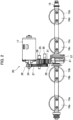
- FIG. 3 is an inner structure diagram of a deceleration mechanism 20 (decelerator). Note that FIG. 3 is a sectional view along the portion A-A illustrated in FIG. 1 .
- the throttle device 10 is a multiple-type throttle device that is attached to a multi-cylinder engine and controls the amount of air intake.
- the throttle device 10 in the present embodiment is employed in an in-line four-cylinder engine 1 mounted in a vehicle such as a motorcycle.
- the engine 1 is disposed in a vehicle such that four cylinders (2a, 2b, 2c, 2d) from #1 to #4 are aligned in order in a vehicle width direction (left-right direction).
- the throttle device 10 includes a first segment body 14a in which an air intake path 13a for the #1 cylinder 2a and an air intake path 13b for the #2 cylinder 2b are formed and a second segment body 14b in which an air intake path 13c for the #3 cylinder 2c and an air intake path 13d for the #4 cylinder 2d are formed.
- the deceleration mechanism 20 is included between the first segment body 14a and the second segment body 14b, that is, between the air intake path 13b for the #2 cylinder 2b and the air intake path 13c for the #3 cylinder 2c. Also, a motor 17 is connected to the deceleration mechanism 20.
- the throttle device 10 further includes a throttle shaft 15, throttle valves 16a to 16d, the deceleration mechanism 20, a return spring 21 (biasing portion), and a throttle position sensor 22.
- FIG. 2 illustrates a structure of a drive portion included inside the throttle device 10, the air intake path 13a is provided with the throttle valve 16a, the air intake path 13b is provided with the throttle valve 16b, the air intake path 13c is provided with the throttle valve 16c, and the air intake path 13d is provided with the throttle valve 16d.
- the first segment body 14a and the second segment body 14b are disposed to be aligned in the left-right direction (vehicle width direction) in accordance with the corresponding cylinders 2a to 2d thereby to form a unit body 23 (throttle body).
- the air intake paths 13a to 13d are formed to extend to be orthogonal (in the front-back direction in FIGS. 1 and 2 ) to the vehicle width direction (left-right direction).
- the throttle shaft 15 penetrates through the unit body 23, extends in the vehicle width direction, passes inside the four air intake paths (13a, 13b, 13c, and 13d), and is rotatably supported by the unit body 23.
- the throttle valves 16a to 16d are disk-shaped members with substantially the same diameter as the inner diameter of the air intake paths 13a to 13d, are secured to the throttle shaft 15, and are disposed inside the air intake paths 13a to 13d.
- the throttle valves 16a to 16d rotate inside the air intake paths 13a to 13d with rotation of the throttle shaft 15 and can rotate and move to an arbitrary angle between a closed position at which the air intake paths 13a to 13d are closed and an open position at which the air intake paths 13a to 13d are opened.
- the motor 17 is an electric motor.
- the motor 17 is secured to the second segment body 14b, and a rotation drive shaft 24 that is an output shaft is disposed to be parallel with the throttle shaft 15.
- the deceleration mechanism 20 is disposed between the first segment body 14a and the second segment body 14b. As illustrated in FIGS. 2 and 3 , the deceleration mechanism 20 includes a first intermediate shaft 25, a second intermediate shaft 30, a first gear 26 secured to the rotation drive shaft 24 of the motor 17, a second gear 27 secured to the first intermediate shaft 25 and engaged with the first gear 26, a third gear 28 secured to the first intermediate shaft 25, a fourth gear 31 secured to the second intermediate shaft 30 and engaged with the third gear 28, and a throttle gear 29 secured to the throttle shaft 15 and engaged with the fourth gear 31.
- the first intermediate shaft 25 and the second intermediate shaft 30 are disposed to be parallel with the rotation drive shaft 24 and the throttle shaft 15 and is rotatably supported by the unit body 23.
- the deceleration mechanism 20 transmits rotation of the rotation drive shaft 24 of the motor 17 in the order of the first gear 26, the second gear 27, the first intermediate shaft 25, the third gear 28, the fourth gear 31, and the throttle gear 29 to decelerate the rotation, and drives and rotates the throttle shaft 15.
- the return spring 21 is a cylindrical torsion spring disposed to be wound several number of times around the throttle shaft 15 and having one end portion supported by the unit body 23 and the other end portion supported by the throttle gear 29 secured to the throttle shaft 15.
- the return spring 21 biases the throttle shaft 15 such that the throttle valves 16c and 16d are brought into a closed state or a fully opened state.
- the throttle position sensor 22 is included at one end portion of the throttle shaft 15 and has a function of detecting a rotation angle of the throttle shaft 15.
- the throttle position sensor 22 is disposed at the second segment body 14b, for example.
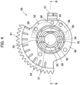
- FIG. 4 is an outer shape diagram of the throttle gear 29.
- FIG. 5 is a vertical sectional view of the throttle gear 29.
- FIG. 6 is a perspective view illustrating the outer shape of a ring 50.
- FIG. 7 is a perspective view illustrating the outer shape of a lever 55. Note that FIG. 4 illustrates a side surface of the throttle gear 29 while FIG. 5 is a sectional view along the part B-B illustrated in FIG. 4 .
- the throttle gear 29 includes a gear main body 40, the ring 50 (ring member), and the lever 55 (support member).
- the gear main body 40 is a disk-shaped gear formed of a resin or the like, and a gear portion 41 such as a spur gear, for example, is formed at a part of the outer circumference.
- a substantially circular ring insertion hole 42 into which the ring 50 is inserted is provided at the center portion. Note that the ring insertion hole 42 has a shape chamfered in parallel with a shaft center interposed therebetween in accordance with the shape of chamfered portions 52 of the ring 50, which will be described later.
- the ring 50 is a cylindrical member formed of metal such as stainless steel and includes a shaft hole 51 provided at the shaft center such that the throttle shaft 15 penetrates therethrough. Also, a pair of chamfered portions 52 chamfered in parallel with a shaft center interposed therebetween are formed on the outer circumferential surface of the ring 50. Moreover, the intermediate portion of the outer circumferential surface of the ring 50 in the axial direction includes a groove 53 with a V-shaped section provided over the entire circumference except for the chamfered portions 52. Also, a securing hole 54 penetrating in parallel with the chamfered portions 52 and passing through the shaft center is formed in the ring 50.
- the lever 55 is configured of a recessed portion 56 disposed to be recessed with a semi-annular shape inside the gear main body 40 and a spring support portion 57 projecting outward in the radial direction from the center portion of the recessed portion 56 in the circumferential direction as illustrated in FIG. 7 .
- the spring support portion 57 extends outward in the radial direction from the outer circumferential end of the recessed portion 56 and projects outward in the radial direction beyond the gear main body 40, and an end portion of the projecting portion is perpendicularly folded and projects by about 1 cm.
- One end portion of the return spring 21 is locked at the spring support portion 57 via a ring-shaped support member, which is not illustrated.
- the other end portion of the return spring 21 is locked at the unit body 23 via a ring-shaped support member 65.
- the return spring 21 is a cylindrical torsion spring and biases the throttle shaft 15 such that the throttle valves 16a to 16d are brought into a closed state or a fully opened state. Then, the throttle gear 29 rotates against the biasing achieved by the return spring 21 via the deceleration mechanism 20 by operating the motor 17.
- the unit body 23 includes a stopper bolt, which is not illustrated, and rotation of the throttle gear 29 is restricted by the distal end thereof abutting the spring support portion 57.
- the spring support portion 57 of the lever 55 also has a function of a stopper that restricts rotation of the throttle shaft 15 more than necessary biased by the return spring 21.
- circular positioning holes 58 are provided in the recessed portion 56 of the lever 55 to be aligned in the circumferential direction.
- the gear main body 40 is provided with a U-shaped groove 43 such that the securing hole 54 of the ring 50 is exposed in a state where the ring 50 is inserted into and secured to the ring insertion hole 42.
- the throttle shaft 15 is provided with a hole with the same diameter as that of the securing hole 54 of the ring 50 passing through the shaft center and extending in the radial direction at the attachment position of the throttle gear 29.
- the throttle gear 29 and the throttle shaft 15 are detachably secured by inserting a pin, which is not illustrated, into the securing hole 54 of the ring 50 in a state where the throttle shaft 15 is inserted into the shaft hole 51 of the ring 50 of the throttle gear 29 and the throttle gear 29 is adjusted at a predetermined axial-direction position and a rotation position of the throttle shaft 15.
- the ring 50 and the lever 55 made of metal are prepared in advance.
- the ring 50 may be manufactured by cutting or casting, for example, and the lever 55 may be manufactured of performing steel metal processing on a metal plate.
- the ring 50 and the lever 55 are set in a mold, and a periphery of the ring 50 and the lever 55 is filled with a material such as a resin to form the gear main body 40.
- a pin with the same diameter as that of the throttle shaft 15 and a pin inserted into the positioning hole 58 of the lever 55 are provided inside the mold, and it is possible to position the ring 50 and the lever 55 with these pins.
- the throttle gear 29 is thus manufactured by insert processing.
- a stopper may be provided separately from the spring support portion 57.
- a stopper with a shape that is similar to that of the spring support portion 57 projecting from the recessed portion 56 outward in the radial direction beyond a position that is different from that of the spring support portion 57 in the circumferential direction may be included.
- the throttle gear 29 may be manufactured by preparing a stopper lever including the recessed portion 56 with a shape that is similar to that of the lever 55 and forming a stopper 60 projecting similarly to the spring support portion 57 as illustrated by the two-dotted dash line in FIG. 3 and insert-processing the stopper lever along with the lever 55 and the ring 50 described above. Note that in this case, it is only necessary to provide, at the unit body 23, a projecting portion 61 which the stopper 60 abuts to restrict the rotation angle range of the throttle gear 29.
- the throttle device 10 drives and rotates the throttle shaft 15 via the deceleration mechanism 20 from the motor 17, the throttle gear 29 of the deceleration mechanism 20 is secured to the throttle shaft 15.
- the gear main body 40 of the throttle gear 29 is formed of a resin, it is possible to achieve weight reduction. Also, the throttle shaft 15 is secured to the metal ring 50 included in the throttle gear 29. It is possible to secure strength of the securing portion between the throttle shaft 15 and the throttle gear 29 by using the ring 50 made of metal.
- the gear main body 40 of the throttle gear 29 is formed of a resin, it is possible to easily form the complicated shape like the gear portion 41. Also, it is possible to easily form the throttle gear 29 through insert processing including the ring 50.
- the ring 50 is inserted into the ring insertion hole 42 of the gear main body 40, and the ring 50 and the gear main body 40 are secured through caulking, for example, the ring 50 may be deformed due to the caulking. Therefore, it is necessary to additionally work the shaft hole 51 of the ring 50 with a reamer or the like after the caulking to enable the throttle shaft 15 to be inserted.
- the ring 50 has a cylindrical shape
- the two chamfered portions 52 are formed on the outer circumferential surface in parallel with the axial line interposed therebetween, and it is thus possible to reliably transmit rotation between the ring 50 and the gear main body 40 by being locked at the ring insertion hole 42 of the gear main body 40 formed in accordance with the shape of the chamfered portion 52.
- the outer circumferential surface of the ring 50 is provided with the groove 53 extending over the entire circumference in the circumferential direction, it is possible to restrict movement of the ring 50 and the gear main body 40 in a thrust direction by a resin entering and being secured to the groove 53 through the insert processing.
- the rotation position and the axial-direction position of the gear main body 40 are defined by the chamfered portions 52 and the groove 53 relative to the cylindrical ring 50, and strong securing is achieved between the ring 50 and the gear main body.
- the throttle gear 29 includes the lever 55 including the spring support portion 57 supporting one end portion of the return spring 21.
- the lever 55 is installed in the mold along with the ring 50 and secured when the gear main body 40 is formed through insert processing. Therefore, it is possible to easily form the throttle gear 29 including the lever 55. Additionally, since the lever 55 is configured to be included in the throttle gear 29, it is possible to configure a part around the support portion of the return spring 21 with a simple structure.
- the insert processing including the ring 50 and the lever 55 is performed when the throttle gear 29 is manufactured in the above embodiment, for example, the throttle gear 29 may be manufactured by performing insert processing only on the ring 50. In this case, the lever 55 may be secured to the throttle gear 29 with a screw or the like.
- the present invention is applied to the throttle device 10 of the four-cylinder engine 1 in the present embodiment, the present invention may be applied to a throttle device of an engine having a plurality of cylinders other than four cylinders.
- the throttle device 10 in the present embodiment drives the throttle valves 16a to 16d with the one motor 17, a plurality of motors may be included, and the number of throttle valves driven by one motor may be a number other than four. Also, a plurality of throttle units in which the motor 17 drives the throttle valves 16 may be included to form the throttle device, and the present invention may be applied to a securing portion between the throttle shaft and to the throttle gear in these throttle units.
- the present invention can also be employed for a throttle device of an engine used for applications other than the motorcycle.
Landscapes
- Engineering & Computer Science (AREA)
- General Engineering & Computer Science (AREA)
- Mechanical Engineering (AREA)
- Chemical & Material Sciences (AREA)
- Combustion & Propulsion (AREA)
- Manufacturing & Machinery (AREA)
- Ceramic Engineering (AREA)
- Control Of Throttle Valves Provided In The Intake System Or In The Exhaust System (AREA)
Abstract
Description
- The present invention relates to a securing structure between a throttle shaft and a drive gear in a throttle device that controls air intake of an engine.
- An engine mounted in a motorcycle or the like includes a throttle device for controlling the amount of air intake. The throttle device is configured to drive a throttle valve provided in an air intake path of the engine using a motor, for example.
- For example,
Japanese Patent Laid-Open No. 2010-53713 - Also, the throttle shaft includes a return spring (pivoting spring) for defining an opening degree of the throttle valve when the motor stops. The return spring is a coil spring provided between a case of the decelerator and a drive gear (driven gear) provided at the throttle shaft and biases the case to rotate the drive gear. Additionally, the drive gear of the throttle shaft and the case include stoppers that restrict a predetermined or larger rotation angle range of the drive gear.
- The drive gear is formed of a resin or the like for weight reduction while the throttle shaft is formed of metal or the like in the throttle device as described above in many cases. Also, including a support portion for the return spring and a stopper at an outer shape portion of a member (lever) including a hole, into which the throttle shaft is inserted, at the center portion and formed of metal or the like into a disk shape to secure strength is conceivable.
- In this manner, a structure in which a tubular ring (bushing) into which the throttle shaft is further inserted is prepared at a securing portion securing the gear made of a resin, the lever including the support portion and the stopper for the return spring, and the throttle shaft, the drive gear including the disk-shaped lever is insert-molded, and a ring is secured to the drive gear including the lever through caulking, for example, is conceivable.
- However, there is a problem in that since the insertion hole for the throttle shaft may collapse and insertion may not be able to be achieved if the caulking is performed on the ring, it is necessary to work the ring after the caulking with a reamer or the like to enable the throttle shaft to be inserted, and this increases manufacturing cost.
- The present invention was made in view of such a problem, and an object thereof is to provide a throttle device capable of facilitating manufacturing of a gear with a complicated structure while securing strength of a portion secured to a throttle shaft and capable of reducing manufacturing cost.
- In order to achieve the above object, a throttle device according to the present invention includes: a throttle shaft to which a throttle valve is secured; a motor; and a decelerator including a gear secured to the throttle shaft, decelerating rotation of a drive shaft of the motor, and transmitting the rotation to the throttle shaft, the gear including a tubular ring member into which the throttle shaft is detachably inserted and a gear main body including a gear portion, and the gear main body being formed by insert processing including the ring member.
- Preferably, the ring member may include a chamfered portion formed at a part of a cylindrical outer circumferential surface that is in contact with the gear main body.
- Preferably, the ring member may be formed by chamfering the cylindrical outer circumferential surface.
- Preferably, the ring member may include a groove extending in a circumferential direction.
- Preferably, the throttle device may further include: a biasing portion rotation-biasing the throttle shaft; and a support member supporting an end of the biasing portion, the gear being integrally formed by insert processing including the support member and the ring member.
- Preferably, the ring member may be formed of metal, and the gear is formed of a resin.
- Preferably, the ring member and the support member may be formed of metal, and the gear is formed of a resin.
- Preferably, the throttle device may be included in an engine of a motorcycle and control the amount of air intake of the engine.
- According to the throttle device of the present invention, the gear secured to the throttle shaft includes the tubular ring member and the gear main body formed through insert processing, and it is thus possible to use different materials for the ring member and the gear main body. Therefore, it is possible to cause the ring member to have relatively high strength and to secure strength of the securing portion between the throttle shaft and the gear. Since the gear main body is formed through insert processing, it is possible to easily form the gear with a complicated shape and to achieve weight reduction of the entire gear by forming the gear from a light material.
- Furthermore, since the ring member and the gear main body are secured through insert processing, deformation of the ring member is curbed, and it is not necessary to perform post-processing after the insert processing. It is thus possible to reduce manufacturing cost of the gear and to provide an inexpensive throttle device.
-
-
FIG. 1 is an external view of a throttle device according to an embodiment of the present invention; -
FIG. 2 is a schematic configuration diagram of a drive portion of the throttle valve; -
FIG. 3 is an internal structure diagram of a deceleration mechanism; -
FIG. 4 is an outer shape diagram of a throttle gear; -
FIG. 5 is a vertical sectional view of the throttle gear; -
FIG. 6 is a perspective view illustrating an outer shape of a ring; and -
FIG. 7 is a perspective view illustrating an outer shape of a lever. - Hereinafter, an embodiment of the present invention will be described on the basis of the drawings.
-
FIG. 1 is an external view of athrottle device 10 according to an embodiment of the present invention.FIG. 2 is a schematic configuration diagram of a drive portion of thethrottle device 10.FIG. 3 is an inner structure diagram of a deceleration mechanism 20 (decelerator). Note thatFIG. 3 is a sectional view along the portion A-A illustrated inFIG. 1 . - The
throttle device 10 according to the present invention is a multiple-type throttle device that is attached to a multi-cylinder engine and controls the amount of air intake. Thethrottle device 10 in the present embodiment is employed in an in-line four-cylinder engine 1 mounted in a vehicle such as a motorcycle. The engine 1 is disposed in a vehicle such that four cylinders (2a, 2b, 2c, 2d) from #1 to #4 are aligned in order in a vehicle width direction (left-right direction). - As illustrated in
FIG. 1 , thethrottle device 10 includes afirst segment body 14a in which anair intake path 13a for the #1cylinder 2a and anair intake path 13b for the #2cylinder 2b are formed and asecond segment body 14b in which anair intake path 13c for the #3cylinder 2c and anair intake path 13d for the #4cylinder 2d are formed. - The
deceleration mechanism 20 is included between thefirst segment body 14a and thesecond segment body 14b, that is, between theair intake path 13b for the #2cylinder 2b and theair intake path 13c for the #3cylinder 2c. Also, amotor 17 is connected to thedeceleration mechanism 20. - As illustrated in
FIGS. 1 and2 , thethrottle device 10 further includes athrottle shaft 15,throttle valves 16a to 16d, thedeceleration mechanism 20, a return spring 21 (biasing portion), and athrottle position sensor 22. Note thatFIG. 2 illustrates a structure of a drive portion included inside thethrottle device 10, theair intake path 13a is provided with thethrottle valve 16a, theair intake path 13b is provided with thethrottle valve 16b, theair intake path 13c is provided with thethrottle valve 16c, and theair intake path 13d is provided with thethrottle valve 16d. - The
first segment body 14a and thesecond segment body 14b are disposed to be aligned in the left-right direction (vehicle width direction) in accordance with thecorresponding cylinders 2a to 2d thereby to form a unit body 23 (throttle body). - The
air intake paths 13a to 13d are formed to extend to be orthogonal (in the front-back direction inFIGS. 1 and2 ) to the vehicle width direction (left-right direction). Thethrottle shaft 15 penetrates through theunit body 23, extends in the vehicle width direction, passes inside the four air intake paths (13a, 13b, 13c, and 13d), and is rotatably supported by theunit body 23. - The
throttle valves 16a to 16d are disk-shaped members with substantially the same diameter as the inner diameter of theair intake paths 13a to 13d, are secured to thethrottle shaft 15, and are disposed inside theair intake paths 13a to 13d. Thethrottle valves 16a to 16d rotate inside theair intake paths 13a to 13d with rotation of thethrottle shaft 15 and can rotate and move to an arbitrary angle between a closed position at which theair intake paths 13a to 13d are closed and an open position at which theair intake paths 13a to 13d are opened. - The
motor 17 is an electric motor. Themotor 17 is secured to thesecond segment body 14b, and arotation drive shaft 24 that is an output shaft is disposed to be parallel with thethrottle shaft 15. - The
deceleration mechanism 20 is disposed between thefirst segment body 14a and thesecond segment body 14b. As illustrated inFIGS. 2 and3 , thedeceleration mechanism 20 includes a firstintermediate shaft 25, a secondintermediate shaft 30, afirst gear 26 secured to therotation drive shaft 24 of themotor 17, asecond gear 27 secured to the firstintermediate shaft 25 and engaged with thefirst gear 26, athird gear 28 secured to the firstintermediate shaft 25, afourth gear 31 secured to the secondintermediate shaft 30 and engaged with thethird gear 28, and athrottle gear 29 secured to thethrottle shaft 15 and engaged with thefourth gear 31. The firstintermediate shaft 25 and the secondintermediate shaft 30 are disposed to be parallel with therotation drive shaft 24 and thethrottle shaft 15 and is rotatably supported by theunit body 23. - The
deceleration mechanism 20 transmits rotation of therotation drive shaft 24 of themotor 17 in the order of thefirst gear 26, thesecond gear 27, the firstintermediate shaft 25, thethird gear 28, thefourth gear 31, and thethrottle gear 29 to decelerate the rotation, and drives and rotates thethrottle shaft 15. - The
return spring 21 is a cylindrical torsion spring disposed to be wound several number of times around thethrottle shaft 15 and having one end portion supported by theunit body 23 and the other end portion supported by thethrottle gear 29 secured to thethrottle shaft 15. Thereturn spring 21 biases thethrottle shaft 15 such that thethrottle valves - The
throttle position sensor 22 is included at one end portion of thethrottle shaft 15 and has a function of detecting a rotation angle of thethrottle shaft 15. Thethrottle position sensor 22 is disposed at thesecond segment body 14b, for example. - Next, a structure of the securing portion between the
throttle shaft 15 and thethrottle gear 29 will be described usingFIGS. 4 to 7 . -
FIG. 4 is an outer shape diagram of thethrottle gear 29.FIG. 5 is a vertical sectional view of thethrottle gear 29.FIG. 6 is a perspective view illustrating the outer shape of aring 50.FIG. 7 is a perspective view illustrating the outer shape of alever 55. Note thatFIG. 4 illustrates a side surface of thethrottle gear 29 whileFIG. 5 is a sectional view along the part B-B illustrated inFIG. 4 . - As illustrated in
FIGS. 4 and5 , thethrottle gear 29 includes a gearmain body 40, the ring 50 (ring member), and the lever 55 (support member). - The gear
main body 40 is a disk-shaped gear formed of a resin or the like, and agear portion 41 such as a spur gear, for example, is formed at a part of the outer circumference. A substantially circularring insertion hole 42 into which thering 50 is inserted is provided at the center portion. Note that thering insertion hole 42 has a shape chamfered in parallel with a shaft center interposed therebetween in accordance with the shape ofchamfered portions 52 of thering 50, which will be described later. - As illustrated in
FIG. 6 , thering 50 is a cylindrical member formed of metal such as stainless steel and includes ashaft hole 51 provided at the shaft center such that thethrottle shaft 15 penetrates therethrough. Also, a pair ofchamfered portions 52 chamfered in parallel with a shaft center interposed therebetween are formed on the outer circumferential surface of thering 50. Moreover, the intermediate portion of the outer circumferential surface of thering 50 in the axial direction includes agroove 53 with a V-shaped section provided over the entire circumference except for thechamfered portions 52. Also, a securinghole 54 penetrating in parallel with the chamferedportions 52 and passing through the shaft center is formed in thering 50. - On the other hand, the
lever 55 is configured of a recessedportion 56 disposed to be recessed with a semi-annular shape inside the gearmain body 40 and aspring support portion 57 projecting outward in the radial direction from the center portion of the recessedportion 56 in the circumferential direction as illustrated inFIG. 7 . - The
spring support portion 57 extends outward in the radial direction from the outer circumferential end of the recessedportion 56 and projects outward in the radial direction beyond the gearmain body 40, and an end portion of the projecting portion is perpendicularly folded and projects by about 1 cm. One end portion of thereturn spring 21 is locked at thespring support portion 57 via a ring-shaped support member, which is not illustrated. The other end portion of thereturn spring 21 is locked at theunit body 23 via a ring-shapedsupport member 65. Thereturn spring 21 is a cylindrical torsion spring and biases thethrottle shaft 15 such that thethrottle valves 16a to 16d are brought into a closed state or a fully opened state. Then, thethrottle gear 29 rotates against the biasing achieved by thereturn spring 21 via thedeceleration mechanism 20 by operating themotor 17. - Note that the
unit body 23 includes a stopper bolt, which is not illustrated, and rotation of thethrottle gear 29 is restricted by the distal end thereof abutting thespring support portion 57. In other words, thespring support portion 57 of thelever 55 also has a function of a stopper that restricts rotation of thethrottle shaft 15 more than necessary biased by thereturn spring 21. - Also, circular positioning holes 58 are provided in the recessed
portion 56 of thelever 55 to be aligned in the circumferential direction. - The gear
main body 40 is provided with aU-shaped groove 43 such that the securinghole 54 of thering 50 is exposed in a state where thering 50 is inserted into and secured to thering insertion hole 42. - Note that the
throttle shaft 15 is provided with a hole with the same diameter as that of the securinghole 54 of thering 50 passing through the shaft center and extending in the radial direction at the attachment position of thethrottle gear 29. - The
throttle gear 29 and thethrottle shaft 15 are detachably secured by inserting a pin, which is not illustrated, into the securinghole 54 of thering 50 in a state where thethrottle shaft 15 is inserted into theshaft hole 51 of thering 50 of thethrottle gear 29 and thethrottle gear 29 is adjusted at a predetermined axial-direction position and a rotation position of thethrottle shaft 15. - Next, a method for manufacturing the
throttle gear 29 will be described. - The
ring 50 and thelever 55 made of metal are prepared in advance. Thering 50 may be manufactured by cutting or casting, for example, and thelever 55 may be manufactured of performing steel metal processing on a metal plate. Next, thering 50 and thelever 55 are set in a mold, and a periphery of thering 50 and thelever 55 is filled with a material such as a resin to form the gearmain body 40. Note that a pin with the same diameter as that of thethrottle shaft 15 and a pin inserted into thepositioning hole 58 of thelever 55 are provided inside the mold, and it is possible to position thering 50 and thelever 55 with these pins. Thethrottle gear 29 is thus manufactured by insert processing. - Note that although the
spring support portion 57 of thelever 55 has a function of supporting one end portion of thereturn spring 21 and also has a function of a stopper restricting a rotation angle range of thethrottle gear 29 in the above embodiment, a stopper may be provided separately from thespring support portion 57. For example, a stopper with a shape that is similar to that of thespring support portion 57 projecting from the recessedportion 56 outward in the radial direction beyond a position that is different from that of thespring support portion 57 in the circumferential direction may be included. - Alternatively, the
throttle gear 29 may be manufactured by preparing a stopper lever including the recessedportion 56 with a shape that is similar to that of thelever 55 and forming astopper 60 projecting similarly to thespring support portion 57 as illustrated by the two-dotted dash line inFIG. 3 and insert-processing the stopper lever along with thelever 55 and thering 50 described above. Note that in this case, it is only necessary to provide, at theunit body 23, a projectingportion 61 which thestopper 60 abuts to restrict the rotation angle range of thethrottle gear 29. - As described above, although the
throttle device 10 according to the present embodiment drives and rotates thethrottle shaft 15 via thedeceleration mechanism 20 from themotor 17, thethrottle gear 29 of thedeceleration mechanism 20 is secured to thethrottle shaft 15. - Since the gear
main body 40 of thethrottle gear 29 is formed of a resin, it is possible to achieve weight reduction. Also, thethrottle shaft 15 is secured to themetal ring 50 included in thethrottle gear 29. It is possible to secure strength of the securing portion between thethrottle shaft 15 and thethrottle gear 29 by using thering 50 made of metal. - Moreover, since the gear
main body 40 of thethrottle gear 29 is formed of a resin, it is possible to easily form the complicated shape like thegear portion 41. Also, it is possible to easily form thethrottle gear 29 through insert processing including thering 50. - Here, in a case where the
ring 50 and the gearmain body 40 are separately manufactured, thering 50 is inserted into thering insertion hole 42 of the gearmain body 40, and thering 50 and the gearmain body 40 are secured through caulking, for example, thering 50 may be deformed due to the caulking. Therefore, it is necessary to additionally work theshaft hole 51 of thering 50 with a reamer or the like after the caulking to enable thethrottle shaft 15 to be inserted. - On the other hand, since the
ring 50 and the gearmain body 40 are secured through insert processing in the present embodiment, deformation of thering 50 is curbed. Post-processing such as reamer processing is thus not necessary, and it is possible to reduce manufacturing cost and to provide aninexpensive throttle device 10. - Also, although the
ring 50 has a cylindrical shape, the two chamferedportions 52 are formed on the outer circumferential surface in parallel with the axial line interposed therebetween, and it is thus possible to reliably transmit rotation between thering 50 and the gearmain body 40 by being locked at thering insertion hole 42 of the gearmain body 40 formed in accordance with the shape of the chamferedportion 52. - Also, since the outer circumferential surface of the
ring 50 is provided with thegroove 53 extending over the entire circumference in the circumferential direction, it is possible to restrict movement of thering 50 and the gearmain body 40 in a thrust direction by a resin entering and being secured to thegroove 53 through the insert processing. - In this manner, the rotation position and the axial-direction position of the gear
main body 40 are defined by the chamferedportions 52 and thegroove 53 relative to thecylindrical ring 50, and strong securing is achieved between thering 50 and the gear main body. - Also, the
throttle gear 29 includes thelever 55 including thespring support portion 57 supporting one end portion of thereturn spring 21. Thelever 55 is installed in the mold along with thering 50 and secured when the gearmain body 40 is formed through insert processing. Therefore, it is possible to easily form thethrottle gear 29 including thelever 55. Additionally, since thelever 55 is configured to be included in thethrottle gear 29, it is possible to configure a part around the support portion of thereturn spring 21 with a simple structure. - Although the description of the embodiment will now be ended, modes of the present invention are not limited to the above embodiment. Although the insert processing including the
ring 50 and thelever 55 is performed when thethrottle gear 29 is manufactured in the above embodiment, for example, thethrottle gear 29 may be manufactured by performing insert processing only on thering 50. In this case, thelever 55 may be secured to thethrottle gear 29 with a screw or the like. - Additionally, although the present invention is applied to the
throttle device 10 of the four-cylinder engine 1 in the present embodiment, the present invention may be applied to a throttle device of an engine having a plurality of cylinders other than four cylinders. - Also, although the
throttle device 10 in the present embodiment drives thethrottle valves 16a to 16d with the onemotor 17, a plurality of motors may be included, and the number of throttle valves driven by one motor may be a number other than four. Also, a plurality of throttle units in which themotor 17 drives the throttle valves 16 may be included to form the throttle device, and the present invention may be applied to a securing portion between the throttle shaft and to the throttle gear in these throttle units. - Furthermore, the present invention can also be employed for a throttle device of an engine used for applications other than the motorcycle.
-
- 1 Engine
- 10 Throttle device
- 15 Throttle shaft
- 16a, 16b, 16c, 16d Throttle valve
- 17 Motor
- 20 Deceleration mechanism (decelerator)
- 21 Return spring (biasing portion)
- 29 Throttle gear (gear)
- 40 Gear main body
- 50 Ring (ring member)
- 52 Chamfered portion
- 53 Groove
- 55 Lever (support member)
Claims (7)
- A throttle device(10) comprising:a throttle shaft(15) to which a throttle valve(16a, 16b, 16c, 16d) is secured;a motor(17); anda decelerator(20) including a gear(29) secured to the throttle shaft(15), decelerating rotation of a drive shaft(24) of the motor(17), and transmitting the rotation to the throttle shaft(15),wherein the gear(29) includes a tubular ring member(50) into which the throttle shaft(15) is detachably inserted and a gear main body(40) including a gear portion(41), andthe gear main body(40) is formed by insert processing including the ring member(50).
- The throttle device according to claim 1, wherein the ring member(50) includes a chamfered portion(52) formed at a part of a cylindrical outer circumferential surface that is in contact with the gear main body(40).
- The throttle device according to claim 1 or 2, wherein the ring member(50) includes a groove(53) extending in a circumferential direction.
- The throttle device according to any one of claims 1 to 3, further comprising:a biasing portion(21) rotation-biasing the throttle shaft(15); anda support member(55) supporting an end of the biasing portion(21),wherein the gear(29) is integrally formed by insert processing including the support member(55) and the ring member(50).
- The throttle device according to any one of claims 1 to 4, wherein the ring member(50) is formed of metal, and the gear(29) is formed of a resin.
- The throttle device according to claim 4, wherein the ring member(50) and the support member(55) are formed of metal, and the gear(29) is formed of a resin.
- The throttle device according to any one of claims 1 to 6, wherein the throttle device (10) is included in an engine(1) of a motorcycle and controls an amount of air intake of the engine (1).
Applications Claiming Priority (1)
| Application Number | Priority Date | Filing Date | Title |
|---|---|---|---|
| JP2022026763A JP7778004B2 (en) | 2022-02-24 | 2022-02-24 | Throttle device |
Publications (2)
| Publication Number | Publication Date |
|---|---|
| EP4234908A2 true EP4234908A2 (en) | 2023-08-30 |
| EP4234908A3 EP4234908A3 (en) | 2023-09-20 |
Family
ID=85285252
Family Applications (1)
| Application Number | Title | Priority Date | Filing Date |
|---|---|---|---|
| EP23157521.8A Pending EP4234908A3 (en) | 2022-02-24 | 2023-02-20 | Throttle device |
Country Status (3)
| Country | Link |
|---|---|
| US (1) | US12247527B2 (en) |
| EP (1) | EP4234908A3 (en) |
| JP (2) | JP7778004B2 (en) |
Families Citing this family (2)
| Publication number | Priority date | Publication date | Assignee | Title |
|---|---|---|---|---|
| JP2024112600A (en) * | 2023-02-08 | 2024-08-21 | 日立Astemo株式会社 | Throttle Device |
| EP4596927A1 (en) * | 2024-02-05 | 2025-08-06 | Microtecnica S.r.l. | Valve system |
Citations (1)
| Publication number | Priority date | Publication date | Assignee | Title |
|---|---|---|---|---|
| JP2010053713A (en) | 2008-08-26 | 2010-03-11 | Mikuni Corp | Throttle device |
Family Cites Families (11)
| Publication number | Priority date | Publication date | Assignee | Title |
|---|---|---|---|---|
| US7716828B2 (en) * | 2004-05-31 | 2010-05-18 | Aisan Kogyo Kabushiki Kaisha | Method of manufacturing throttle body, and throttle body |
| JP4104594B2 (en) * | 2004-12-22 | 2008-06-18 | 株式会社ケーヒン | Engine intake control system |
| JP4457038B2 (en) * | 2005-04-14 | 2010-04-28 | 日立オートモティブシステムズ株式会社 | Motor driven throttle control device for internal combustion engine |
| DE102006030097B3 (en) * | 2006-06-28 | 2008-02-14 | Zf Friedrichshafen Ag | screw gear |
| JP4513892B2 (en) * | 2008-04-11 | 2010-07-28 | 株式会社デンソー | Manufacturing method of valve unit |
| JP5180170B2 (en) * | 2009-09-09 | 2013-04-10 | 愛三工業株式会社 | Electronically controlled throttle control device |
| DE102010045215A1 (en) | 2010-09-13 | 2012-03-15 | Audi Ag | Switch shaft and method for producing a switching shaft |
| JP5854261B2 (en) * | 2011-09-13 | 2016-02-09 | 株式会社ジェイテクト | Worm wheel |
| US9638108B2 (en) * | 2012-11-27 | 2017-05-02 | Continental Automotive Systems, Inc. | Sector gear with integrated bushing |
| JP6496536B2 (en) * | 2014-12-05 | 2019-04-03 | ダイセルポリマー株式会社 | Shaft integrated gear and manufacturing method thereof |
| CN113503212A (en) | 2021-07-05 | 2021-10-15 | 四川红光汽车机电有限公司 | Novel electronic throttle valve body for diesel engine |
-
2022
- 2022-02-24 JP JP2022026763A patent/JP7778004B2/en active Active
-
2023
- 2023-02-08 US US18/166,250 patent/US12247527B2/en active Active
- 2023-02-20 EP EP23157521.8A patent/EP4234908A3/en active Pending
-
2025
- 2025-11-10 JP JP2025189279A patent/JP2026012454A/en active Pending
Patent Citations (1)
| Publication number | Priority date | Publication date | Assignee | Title |
|---|---|---|---|---|
| JP2010053713A (en) | 2008-08-26 | 2010-03-11 | Mikuni Corp | Throttle device |
Also Published As
| Publication number | Publication date |
|---|---|
| JP2023122975A (en) | 2023-09-05 |
| US12247527B2 (en) | 2025-03-11 |
| US20230265801A1 (en) | 2023-08-24 |
| EP4234908A3 (en) | 2023-09-20 |
| JP2026012454A (en) | 2026-01-23 |
| JP7778004B2 (en) | 2025-12-01 |
Similar Documents
| Publication | Publication Date | Title |
|---|---|---|
| US12247527B2 (en) | Throttle device | |
| JP3161978B2 (en) | Engine throttle device | |
| CN115163313B (en) | Throttle device | |
| JP7259637B2 (en) | Throttle valve device | |
| JP6675959B2 (en) | Throttle device and method of manufacturing the same | |
| CN109863672A (en) | Rotary actuator, rotary drive device, and shift-by-wire system using the same | |
| JP2006291912A (en) | Motor driven throttle control device for internal combustion engine | |
| US11306665B2 (en) | Throttle device | |
| JP2009162073A (en) | Electronic throttle device for internal combustion engines | |
| US20230400103A1 (en) | Throttle valve device and method for manufacturing the same | |
| JP4502916B2 (en) | Throttle valve control device | |
| US20210364082A1 (en) | Shift device | |
| EP3832115B1 (en) | Throttle device | |
| WO2020129849A1 (en) | Throttle device and method for manufacturing throttle device | |
| EP3904662B1 (en) | Throttle device | |
| JPH0759900B2 (en) | Throttle opening and closing device for internal combustion engine | |
| KR20210106569A (en) | valve timing adjustment device | |
| JP7388899B2 (en) | throttle device | |
| JP2002266666A (en) | Intake throttle device for internal combustion engine | |
| JP2021088960A (en) | Throttle device | |
| WO2021038641A1 (en) | Electronically controlled throttle device for engine | |
| JP2007064314A (en) | Actuator and actuator assembly method | |
| JP2024055760A (en) | Valve device | |
| JP2004108301A (en) | Maximum vehicle speed limiting device | |
| JP2002295270A (en) | Throttle device for internal combustion engine |
Legal Events
| Date | Code | Title | Description |
|---|---|---|---|
| PUAI | Public reference made under article 153(3) epc to a published international application that has entered the european phase |
Free format text: ORIGINAL CODE: 0009012 |
|
| STAA | Information on the status of an ep patent application or granted ep patent |
Free format text: STATUS: THE APPLICATION HAS BEEN PUBLISHED |
|
| REG | Reference to a national code |
Ref country code: DE Ref legal event code: R079 Free format text: PREVIOUS MAIN CLASS: F02D0009020000 Ipc: F02D0009100000 |
|
| PUAL | Search report despatched |
Free format text: ORIGINAL CODE: 0009013 |
|
| AK | Designated contracting states |
Kind code of ref document: A2 Designated state(s): AL AT BE BG CH CY CZ DE DK EE ES FI FR GB GR HR HU IE IS IT LI LT LU LV MC ME MK MT NL NO PL PT RO RS SE SI SK SM TR |
|
| AK | Designated contracting states |
Kind code of ref document: A3 Designated state(s): AL AT BE BG CH CY CZ DE DK EE ES FI FR GB GR HR HU IE IS IT LI LT LU LV MC ME MK MT NL NO PL PT RO RS SE SI SK SM TR |
|
| RIC1 | Information provided on ipc code assigned before grant |
Ipc: F16K 27/02 20060101ALI20230814BHEP Ipc: F02D 9/02 20060101ALI20230814BHEP Ipc: F02D 9/10 20060101AFI20230814BHEP |
|
| STAA | Information on the status of an ep patent application or granted ep patent |
Free format text: STATUS: REQUEST FOR EXAMINATION WAS MADE |
|
| 17P | Request for examination filed |
Effective date: 20240318 |
|
| RBV | Designated contracting states (corrected) |
Designated state(s): AL AT BE BG CH CY CZ DE DK EE ES FI FR GB GR HR HU IE IS IT LI LT LU LV MC ME MK MT NL NO PL PT RO RS SE SI SK SM TR |
|
| STAA | Information on the status of an ep patent application or granted ep patent |
Free format text: STATUS: EXAMINATION IS IN PROGRESS |
|
| 17Q | First examination report despatched |
Effective date: 20250312 |
|
| GRAP | Despatch of communication of intention to grant a patent |
Free format text: ORIGINAL CODE: EPIDOSNIGR1 |
|
| STAA | Information on the status of an ep patent application or granted ep patent |
Free format text: STATUS: GRANT OF PATENT IS INTENDED |
|
| INTG | Intention to grant announced |
Effective date: 20260323 |