EP4234897A2 - Axle assembly having a dipstick assembly - Google Patents
Axle assembly having a dipstick assembly Download PDFInfo
- Publication number
- EP4234897A2 EP4234897A2 EP23176106.5A EP23176106A EP4234897A2 EP 4234897 A2 EP4234897 A2 EP 4234897A2 EP 23176106 A EP23176106 A EP 23176106A EP 4234897 A2 EP4234897 A2 EP 4234897A2
- Authority
- EP
- European Patent Office
- Prior art keywords
- dipstick
- assembly
- fitting
- hole
- magnet
- Prior art date
- Legal status (The legal status is an assumption and is not a legal conclusion. Google has not performed a legal analysis and makes no representation as to the accuracy of the status listed.)
- Pending
Links
- 239000000314 lubricant Substances 0.000 claims abstract description 59
- 125000006850 spacer group Chemical group 0.000 claims description 9
- 238000005259 measurement Methods 0.000 description 7
- 238000007689 inspection Methods 0.000 description 5
- 230000000712 assembly Effects 0.000 description 4
- 238000000429 assembly Methods 0.000 description 4
- 238000001514 detection method Methods 0.000 description 4
- 239000002184 metal Substances 0.000 description 4
- 238000009434 installation Methods 0.000 description 3
- 239000000853 adhesive Substances 0.000 description 2
- 230000001070 adhesive effect Effects 0.000 description 2
- 238000002485 combustion reaction Methods 0.000 description 2
- 230000005484 gravity Effects 0.000 description 2
- 239000000463 material Substances 0.000 description 2
- 238000011179 visual inspection Methods 0.000 description 2
- CWYNVVGOOAEACU-UHFFFAOYSA-N Fe2+ Chemical compound [Fe+2] CWYNVVGOOAEACU-UHFFFAOYSA-N 0.000 description 1
- 239000012530 fluid Substances 0.000 description 1
- 239000000446 fuel Substances 0.000 description 1
- 230000001050 lubricating effect Effects 0.000 description 1
- 238000000034 method Methods 0.000 description 1
- 238000005065 mining Methods 0.000 description 1
- 238000000926 separation method Methods 0.000 description 1
Images


Classifications
-
- B—PERFORMING OPERATIONS; TRANSPORTING
- B60—VEHICLES IN GENERAL
- B60B—VEHICLE WHEELS; CASTORS; AXLES FOR WHEELS OR CASTORS; INCREASING WHEEL ADHESION
- B60B35/00—Axle units; Parts thereof ; Arrangements for lubrication of axles
-
- F—MECHANICAL ENGINEERING; LIGHTING; HEATING; WEAPONS; BLASTING
- F16—ENGINEERING ELEMENTS AND UNITS; GENERAL MEASURES FOR PRODUCING AND MAINTAINING EFFECTIVE FUNCTIONING OF MACHINES OR INSTALLATIONS; THERMAL INSULATION IN GENERAL
- F16N—LUBRICATING
- F16N19/00—Lubricant containers for use in lubricators or lubrication systems
- F16N19/003—Indicating oil level
-
- F—MECHANICAL ENGINEERING; LIGHTING; HEATING; WEAPONS; BLASTING
- F16—ENGINEERING ELEMENTS AND UNITS; GENERAL MEASURES FOR PRODUCING AND MAINTAINING EFFECTIVE FUNCTIONING OF MACHINES OR INSTALLATIONS; THERMAL INSULATION IN GENERAL
- F16H—GEARING
- F16H57/00—General details of gearing
- F16H57/04—Features relating to lubrication or cooling or heating
- F16H57/0402—Cleaning of lubricants, e.g. filters or magnets
-
- B—PERFORMING OPERATIONS; TRANSPORTING
- B03—SEPARATION OF SOLID MATERIALS USING LIQUIDS OR USING PNEUMATIC TABLES OR JIGS; MAGNETIC OR ELECTROSTATIC SEPARATION OF SOLID MATERIALS FROM SOLID MATERIALS OR FLUIDS; SEPARATION BY HIGH-VOLTAGE ELECTRIC FIELDS
- B03C—MAGNETIC OR ELECTROSTATIC SEPARATION OF SOLID MATERIALS FROM SOLID MATERIALS OR FLUIDS; SEPARATION BY HIGH-VOLTAGE ELECTRIC FIELDS
- B03C1/00—Magnetic separation
- B03C1/02—Magnetic separation acting directly on the substance being separated
- B03C1/025—High gradient magnetic separators
- B03C1/031—Component parts; Auxiliary operations
- B03C1/033—Component parts; Auxiliary operations characterised by the magnetic circuit
- B03C1/0332—Component parts; Auxiliary operations characterised by the magnetic circuit using permanent magnets
-
- B—PERFORMING OPERATIONS; TRANSPORTING
- B03—SEPARATION OF SOLID MATERIALS USING LIQUIDS OR USING PNEUMATIC TABLES OR JIGS; MAGNETIC OR ELECTROSTATIC SEPARATION OF SOLID MATERIALS FROM SOLID MATERIALS OR FLUIDS; SEPARATION BY HIGH-VOLTAGE ELECTRIC FIELDS
- B03C—MAGNETIC OR ELECTROSTATIC SEPARATION OF SOLID MATERIALS FROM SOLID MATERIALS OR FLUIDS; SEPARATION BY HIGH-VOLTAGE ELECTRIC FIELDS
- B03C1/00—Magnetic separation
- B03C1/02—Magnetic separation acting directly on the substance being separated
- B03C1/28—Magnetic plugs and dipsticks
- B03C1/286—Magnetic plugs and dipsticks disposed at the inner circumference of a recipient, e.g. magnetic drain bolt
-
- B—PERFORMING OPERATIONS; TRANSPORTING
- B03—SEPARATION OF SOLID MATERIALS USING LIQUIDS OR USING PNEUMATIC TABLES OR JIGS; MAGNETIC OR ELECTROSTATIC SEPARATION OF SOLID MATERIALS FROM SOLID MATERIALS OR FLUIDS; SEPARATION BY HIGH-VOLTAGE ELECTRIC FIELDS
- B03C—MAGNETIC OR ELECTROSTATIC SEPARATION OF SOLID MATERIALS FROM SOLID MATERIALS OR FLUIDS; SEPARATION BY HIGH-VOLTAGE ELECTRIC FIELDS
- B03C1/00—Magnetic separation
- B03C1/02—Magnetic separation acting directly on the substance being separated
- B03C1/28—Magnetic plugs and dipsticks
- B03C1/288—Magnetic plugs and dipsticks disposed at the outer circumference of a recipient
-
- B—PERFORMING OPERATIONS; TRANSPORTING
- B60—VEHICLES IN GENERAL
- B60B—VEHICLE WHEELS; CASTORS; AXLES FOR WHEELS OR CASTORS; INCREASING WHEEL ADHESION
- B60B35/00—Axle units; Parts thereof ; Arrangements for lubrication of axles
- B60B35/12—Torque-transmitting axles
- B60B35/16—Axle housings
- B60B35/163—Axle housings characterised by specific shape of the housing, e.g. adaptations to give space for other vehicle elements like chassis or exhaust system
-
- F—MECHANICAL ENGINEERING; LIGHTING; HEATING; WEAPONS; BLASTING
- F01—MACHINES OR ENGINES IN GENERAL; ENGINE PLANTS IN GENERAL; STEAM ENGINES
- F01M—LUBRICATING OF MACHINES OR ENGINES IN GENERAL; LUBRICATING INTERNAL COMBUSTION ENGINES; CRANKCASE VENTILATING
- F01M11/00—Component parts, details or accessories, not provided for in, or of interest apart from, groups F01M1/00 - F01M9/00
- F01M11/10—Indicating devices; Other safety devices
- F01M11/12—Indicating devices; Other safety devices concerning lubricant level
-
- F—MECHANICAL ENGINEERING; LIGHTING; HEATING; WEAPONS; BLASTING
- F16—ENGINEERING ELEMENTS AND UNITS; GENERAL MEASURES FOR PRODUCING AND MAINTAINING EFFECTIVE FUNCTIONING OF MACHINES OR INSTALLATIONS; THERMAL INSULATION IN GENERAL
- F16H—GEARING
- F16H57/00—General details of gearing
- F16H57/02—Gearboxes; Mounting gearing therein
- F16H57/037—Gearboxes for accommodating differential gearings
-
- F—MECHANICAL ENGINEERING; LIGHTING; HEATING; WEAPONS; BLASTING
- F16—ENGINEERING ELEMENTS AND UNITS; GENERAL MEASURES FOR PRODUCING AND MAINTAINING EFFECTIVE FUNCTIONING OF MACHINES OR INSTALLATIONS; THERMAL INSULATION IN GENERAL
- F16H—GEARING
- F16H57/00—General details of gearing
- F16H57/04—Features relating to lubrication or cooling or heating
- F16H57/0447—Control of lubricant levels, e.g. lubricant level control dependent on temperature
- F16H57/0449—Sensors or indicators for controlling the fluid level
-
- F—MECHANICAL ENGINEERING; LIGHTING; HEATING; WEAPONS; BLASTING
- F16—ENGINEERING ELEMENTS AND UNITS; GENERAL MEASURES FOR PRODUCING AND MAINTAINING EFFECTIVE FUNCTIONING OF MACHINES OR INSTALLATIONS; THERMAL INSULATION IN GENERAL
- F16H—GEARING
- F16H57/00—General details of gearing
- F16H57/04—Features relating to lubrication or cooling or heating
- F16H57/045—Lubricant storage reservoirs, e.g. reservoirs in addition to a gear sump for collecting lubricant in the upper part of a gear case
- F16H57/0452—Oil pans
-
- G—PHYSICS
- G01—MEASURING; TESTING
- G01F—MEASURING VOLUME, VOLUME FLOW, MASS FLOW OR LIQUID LEVEL; METERING BY VOLUME
- G01F23/00—Indicating or measuring liquid level or level of fluent solid material, e.g. indicating in terms of volume or indicating by means of an alarm
- G01F23/04—Indicating or measuring liquid level or level of fluent solid material, e.g. indicating in terms of volume or indicating by means of an alarm by dip members, e.g. dip-sticks
-
- B—PERFORMING OPERATIONS; TRANSPORTING
- B03—SEPARATION OF SOLID MATERIALS USING LIQUIDS OR USING PNEUMATIC TABLES OR JIGS; MAGNETIC OR ELECTROSTATIC SEPARATION OF SOLID MATERIALS FROM SOLID MATERIALS OR FLUIDS; SEPARATION BY HIGH-VOLTAGE ELECTRIC FIELDS
- B03C—MAGNETIC OR ELECTROSTATIC SEPARATION OF SOLID MATERIALS FROM SOLID MATERIALS OR FLUIDS; SEPARATION BY HIGH-VOLTAGE ELECTRIC FIELDS
- B03C2201/00—Details of magnetic or electrostatic separation
- B03C2201/18—Magnetic separation whereby the particles are suspended in a liquid
-
- B—PERFORMING OPERATIONS; TRANSPORTING
- B03—SEPARATION OF SOLID MATERIALS USING LIQUIDS OR USING PNEUMATIC TABLES OR JIGS; MAGNETIC OR ELECTROSTATIC SEPARATION OF SOLID MATERIALS FROM SOLID MATERIALS OR FLUIDS; SEPARATION BY HIGH-VOLTAGE ELECTRIC FIELDS
- B03C—MAGNETIC OR ELECTROSTATIC SEPARATION OF SOLID MATERIALS FROM SOLID MATERIALS OR FLUIDS; SEPARATION BY HIGH-VOLTAGE ELECTRIC FIELDS
- B03C2201/00—Details of magnetic or electrostatic separation
- B03C2201/28—Parts being easily removable for cleaning purposes
-
- B—PERFORMING OPERATIONS; TRANSPORTING
- B03—SEPARATION OF SOLID MATERIALS USING LIQUIDS OR USING PNEUMATIC TABLES OR JIGS; MAGNETIC OR ELECTROSTATIC SEPARATION OF SOLID MATERIALS FROM SOLID MATERIALS OR FLUIDS; SEPARATION BY HIGH-VOLTAGE ELECTRIC FIELDS
- B03C—MAGNETIC OR ELECTROSTATIC SEPARATION OF SOLID MATERIALS FROM SOLID MATERIALS OR FLUIDS; SEPARATION BY HIGH-VOLTAGE ELECTRIC FIELDS
- B03C2201/00—Details of magnetic or electrostatic separation
- B03C2201/30—Details of magnetic or electrostatic separation for use in or with vehicles
-
- F—MECHANICAL ENGINEERING; LIGHTING; HEATING; WEAPONS; BLASTING
- F01—MACHINES OR ENGINES IN GENERAL; ENGINE PLANTS IN GENERAL; STEAM ENGINES
- F01M—LUBRICATING OF MACHINES OR ENGINES IN GENERAL; LUBRICATING INTERNAL COMBUSTION ENGINES; CRANKCASE VENTILATING
- F01M11/00—Component parts, details or accessories, not provided for in, or of interest apart from, groups F01M1/00 - F01M9/00
- F01M11/04—Filling or draining lubricant of or from machines or engines
- F01M11/0408—Sump drainage devices, e.g. valves, plugs
- F01M2011/0416—Plugs
- F01M2011/0441—Plugs for measuring the lubricant level
-
- F—MECHANICAL ENGINEERING; LIGHTING; HEATING; WEAPONS; BLASTING
- F16—ENGINEERING ELEMENTS AND UNITS; GENERAL MEASURES FOR PRODUCING AND MAINTAINING EFFECTIVE FUNCTIONING OF MACHINES OR INSTALLATIONS; THERMAL INSULATION IN GENERAL
- F16H—GEARING
- F16H57/00—General details of gearing
- F16H57/02—Gearboxes; Mounting gearing therein
- F16H2057/02039—Gearboxes for particular applications
- F16H2057/02043—Gearboxes for particular applications for vehicle transmissions
- F16H2057/02052—Axle units; Transfer casings for four wheel drive
-
- F—MECHANICAL ENGINEERING; LIGHTING; HEATING; WEAPONS; BLASTING
- F16—ENGINEERING ELEMENTS AND UNITS; GENERAL MEASURES FOR PRODUCING AND MAINTAINING EFFECTIVE FUNCTIONING OF MACHINES OR INSTALLATIONS; THERMAL INSULATION IN GENERAL
- F16H—GEARING
- F16H57/00—General details of gearing
- F16H57/04—Features relating to lubrication or cooling or heating
- F16H57/0457—Splash lubrication
-
- F—MECHANICAL ENGINEERING; LIGHTING; HEATING; WEAPONS; BLASTING
- F16—ENGINEERING ELEMENTS AND UNITS; GENERAL MEASURES FOR PRODUCING AND MAINTAINING EFFECTIVE FUNCTIONING OF MACHINES OR INSTALLATIONS; THERMAL INSULATION IN GENERAL
- F16H—GEARING
- F16H57/00—General details of gearing
- F16H57/04—Features relating to lubrication or cooling or heating
- F16H57/048—Type of gearings to be lubricated, cooled or heated
- F16H57/0482—Gearings with gears having orbital motion
- F16H57/0483—Axle or inter-axle differentials
Definitions
- the dipstick assembly may facilitate measurement of a level of lubricant in a housing assembly.
- an axle assembly may include a housing assembly and a dipstick assembly.
- the housing assembly may at least partially define a cavity that receives lubricant.
- the dipstick assembly may include a fitting, a cap, and a dipstick.
- the fitting may be mounted to the housing assembly and may define a fitting hole that is disposed along an axis.
- the cap may be removably mountable to the fitting.
- the dipstick may include a first end portion, a second end portion, a first intermediate portion, and a second intermediate portion.
- the first end portion may be mounted to the cap.
- the second end portion may be disposed opposite the first end portion.
- the first intermediate portion may extend from the first end portion and may be at least partially received in the fitting hole when the cap is mounted to the fitting.
- the second intermediate portion may extend from the first intermediate portion to the second end portion.
- the second intermediate portion may be disposed outside of the fitting hole when the cap is mounted to the fitting.
- the second intermediate portion may be disposed substantially perpendic
- an axle assembly may include a housing assembly and a dipstick assembly.
- the housing assembly may have a mounting hole and may at least partially define a cavity that receives lubricant.
- the dipstick assembly may be removably mountable to the housing assembly.
- the dipstick assembly may include a fitting and a dipstick.
- the fitting may be removably mountable to the housing assembly, may be receivable in the mounting hole, and may be disposed along an axis.
- the dipstick may be rotatably mounted to the fitting such that the dipstick is rotatable about the axis independent of the fitting.
- the axle assembly 10 may be provided with a motor vehicle like a truck, bus, farm equipment, mining equipment, military transport or weaponry vehicle, or cargo loading equipment for land, air, or marine vessels.
- the motor vehicle may include a trailer for transporting cargo in one or more embodiments.
- the axle assembly 10 may provide torque to one or more traction wheel assemblies that may include a tire mounted on a wheel.
- the wheel may be mounted to a wheel hub that may be rotatable about a wheel axis.
- axle assembly 10 may include a housing assembly 20, a differential assembly 22, at least one axle shaft 24, and a dipstick assembly 26.
- the housing assembly 20 may receive various components of the axle assembly 10.
- the housing assembly 20 may facilitate mounting of the axle assembly 10 to the vehicle.
- the housing assembly 20 may include an axle housing 30, a differential carrier 32, and a mounting hole 34.
- the axle housing 30 may receive and may support the axle shafts 24, which are best shown in Figure 1 .
- the axle housing 30 may include a center portion 40 and at least one arm portion 42.
- the center portion 40 may be disposed proximate the center of the axle housing 30.
- the center portion 40 may at least partially define a cavity 44 that may at least partially receive the differential assembly 22.
- a lower region of the center portion 40 and the cavity 44 may at least partially define a sump portion 46 that may contain or collect lubricant 48.
- the lubricant 48 may be a lubricating fluid such as oil.
- Lubricant 48 in the sump portion 46 may be splashed by a ring gear of the differential assembly 22 and distributed to lubricate various components when the differential assembly 22 rotates.
- Lubricant 48 may collect in the sump portion 46 and increase the level of lubricant 48 in the sump portion 46 when the differential assembly 22 does not rotate.
- the center portion 40 is illustrated with a bowl cover exploded from the axle housing 30 to better show features inside the axle housing 30; however, it is contemplated that the bowl cover or a portion thereof may be integrally formed with one or more components that make up the axle housing 30 and may not be removable in the manner shown.
- the cavity 44 will be primarily described in the context as being the cavity that includes the sump portion 46; however, it is contemplated that the cavity 44 may be provided in different locations, such as in an arm portion 42 of the housing assembly 20 when the arm portion 42 is configured to collect lubricant 48 or function as a lubricant reservoir.
- the center portion 40 may facilitate mounting of the differential carrier 32 to the axle housing 30.
- the center portion 40 may have a set of holes that may be aligned with corresponding holes on the differential carrier 32. Each hole may receive a fastener, such as a bolt, that may couple the differential carrier 32 to the axle housing 30.
- one or more arm portions 42 may extend from the center portion 40.
- two arm portions 42 may extend in opposite directions from the center portion 40 and away from the differential assembly 22.
- the arm portions 42 may have substantially similar configurations.
- the arm portions 42 may each have a hollow configuration or tubular configuration that may extend around and may receive a corresponding axle shaft 24 and may help separate or isolate the axle shaft 24 or a portion thereof from the surrounding environment.
- An arm portion 42 or a portion thereof may or may not be integrally formed with the center portion 40. It is also contemplated that the arm portions 42 may be omitted.
- the differential carrier 32 may be mounted to the center portion 40 of the axle housing 30.
- the differential carrier 32 may support the differential assembly 22.
- the differential carrier 32 may include one or more bearing supports 50 that may support a roller bearing assembly that may rotatably support the differential assembly 22.
- the mounting hole 34 may be a through hole that extends through a wall of the housing assembly 20.
- the mounting hole 34 may be provided in any suitable location.
- the mounting hole 34 may be provided in the axle housing 30, the differential carrier 32, or both.
- the mounting hole 34 may be positioned above a maximum lubricant fill level of the axle assembly 10 so that the free end of the dipstick of the dipstick assembly 26 may extend downward toward the lubricant 48 and so that lubricant 48 may not drain out of the housing assembly 20 via the mounting hole 34 when the vehicle is positioned upright on a substantially level or substantially horizontal surface.
- the differential assembly 22 may be at least partially received in the center portion 40 of the housing assembly 20.
- the differential assembly 22 may be rotatable about a differential axis 60 and may transmit torque to its associated traction wheel assemblies via the axle shafts 24.
- the differential assembly 22 may be operatively connected to the axle shafts 24 and may permit the axle shafts 24 to rotate at different rotational speeds in a manner known by those skilled in the art.
- the differential assembly 22 may have a ring gear 62 that may have teeth the mate or mesh with the teeth of a gear portion of a drive pinion that may be operatively connected to a power source.
- the ring gear 62 may be fixedly disposed on a differential case of the differential assembly 22 such that the differential case and ring gear 62 may be rotatable together about the differential axis 60.
- a differential gear set of the differential assembly 22 may transmit torque to the axle shafts 24 in a manner known by those skilled in the art. Accordingly, the differential assembly 22 may receive torque from the drive pinion via the ring gear 62 and transmit torque to the axle shafts 24.
- the power source may be of any suitable type.
- the power source may be an electrical power source or a non-electrical power source.
- An example of an electrical power source is an electrical machine like an electric motor.
- An example of a non-electrical power source is an internal combustion engine.
- the power source may be configured as an electric motor that is provided with the axle assembly 10; however, it is contemplated that the power source, whether electrical or non-electrical, may not be provided with the axle assembly 10.
- the power source may be located remotely from the axle assembly 10 and may be operatively connected to the axle assembly 10 via a linkage like a shaft.
- the axle shafts 24 may transmit torque from the differential assembly 22 to corresponding wheel hubs and wheels.
- Two axle shafts 24 may be provided such that each axle shaft 24 extends through a different arm portion 42 of axle housing 30.
- the axle shafts 24 may extend along and may be rotatable about an axis, such as the differential axis 60.
- Each axle shaft 24 may have a first end and a second end. The first end may be operatively connected to the differential assembly 22. The second end may be disposed opposite the first end and may be operatively connected to a wheel.
- gear reduction may be provided between an axle shaft 24 and a wheel.
- the dipstick assembly 26 may facilitate inspection of the level of lubricant 48 in a portion of the housing assembly 20, such as the sump portion 46.
- the dipstick assembly 26 may include a fitting 70, a cap 72, and a dipstick 78.
- the dipstick assembly 26 may also include a magnet 80, a biasing member 82, a seal 84, or combinations thereof.
- the fitting 70 may be mounted to the housing assembly 20. For instance, the fitting may be partially received inside the mounting hole 34 of the housing assembly 20. In at least one configuration, the fitting 70 may have a first end 90, a second end 92, a fitting hole 94, a mounting portion 96, and a tool engagement portion 98. The fitting 70 may also include a mounting ring 100, a recess 104, a protrusion 102, or combinations thereof.
- the first end 90 may face away from the housing assembly 20.
- the first end 90 may also be disposed outside of the housing assembly 20.
- the second end 92 may be disposed opposite the first end 90.
- the second end 92 may be disposed inside the housing assembly 20 or its mounting hole 34.
- the fitting hole 94 may be defined by the fitting 70.
- the fitting hole 94 may be a through hole that may extend from the first end 90 to the second end 92.
- the fitting hole 94 may extend along an axis 110.
- the axis 110 may extend in a horizontal or have substantially horizontal direction rather than in a vertical or substantially vertical direction as may be associated with a dipstick for measuring the oil level in an internal combustion engine.
- the mounting portion 96 may facilitate mounting of the fitting 70 to the housing assembly 20.
- the mounting portion 96 is threaded and is configured to mate with a corresponding thread in the mounting hole 34.
- the mounting portion 96 may not be threaded and may be attached to the housing assembly 20 in another manner, including but not limited to an interference fit, or with a weld, adhesive, or the like.
- the tool engagement portion 98 may be axially positioned between the first end 90 and the second end 92.
- the tool engagement portion 98 may be axially positioned between the mounting portion 96 and the mounting ring 100.
- the tool engagement portion 98 may be disposed outside of the housing assembly 20.
- the tool engagement portion 98 may include one or more flat surfaces that may be engageable with a tool, such as a socket or a wrench, to facilitate installation of the fitting 70 on the housing assembly 20.
- the mounting ring 100 may facilitate mounting of the cap 72.
- the mounting ring 100 may be disposed outside of the housing assembly 20.
- the mounting ring 100 may extend in an axial direction from the first end 90 toward the second end 92.
- the mounting ring 100 may extend continuously around the axis 110.
- the protrusion 102 may be disposed outside of the housing assembly 20. As such, the protrusion 102 may be disposed outside of the cavity 44.
- the protrusion 102 may extend from the mounting ring 100 in a direction that may extend away from the axis 110.
- the protrusion 102 may have an enlarged head disposed at its distal end.
- the recess 104 may be configured to receive and position the magnet 80.
- the recess 104 may extend from the second end 92 toward the first end 90.
- the recess 104 may extend radially outward from the fitting hole 94 toward the mounting portion 96 such that the recess 104 may have a larger diameter than the fitting hole 94.
- the cap 72 may be removably mountable to the fitting 70.
- the cap 72 may be disposed outside of the housing assembly 20 and may facilitate installation and removal of the dipstick 78 as will be described in more detail below.
- the cap 72 may define a mounting feature 120.
- the cap 72 may also include a groove 122, an inner ring 124, an outer ring 126, a slot 128, or combinations thereof.
- the mounting feature 120 may facilitate mounting of the dipstick 78 to the cap 72.
- the mounting feature 120 may have a male configuration, a female configuration, or combinations thereof. In the configuration shown, the mounting feature 120 has a female configuration and is configured as a blind hole.
- the mounting feature 120 may be disposed along the axis 110 and may receive an end of the dipstick 78.
- the groove 122 may be spaced apart from and may extend around the mounting feature 120.
- the groove 122 may receive the mounting ring 100 of the fitting 70 when the cap 72 is mounted to the fitting 70.
- the groove 122 may be defined by the inner ring 124, the outer ring 126, or both.
- the inner ring 124 may be radially positioned between the mounting feature 120 and the groove 122.
- the inner ring 124 may be received inside the fitting hole 94 when the cap 72 is mounted to the fitting 70.
- the inner ring 124 may include a seal groove that may receive the seal 84.
- the outer ring 126 may extend around the mounting ring 100 of the fitting 70. In addition, the outer ring 126 may extend around the inner ring 124, if provided, and the axis 110.
- the slot 128 may be configured to receive the protrusion 102 on the fitting 70 to inhibit removal of the cap 72.
- the slot 128 may extend through the outer ring 126 and may have a generally L-shaped configuration that may extend from an open end to a closed end. The open end may face toward the fitting 70.
- the slot 128 may extend axially from the open end in a direction that extends away from the fitting 70 to a bend.
- the slot 128 may change direction at the bend and may extend in a circumferential direction around the outer ring 126 to the closed end.
- the protrusion 102 and the slot 128 may cooperate to secure the cap.
- the cap 72 and the fitting 70 may be axially aligned such that the inner ring 124 may be axially insertable into the fitting hole 94.
- the cap 72 and the fitting 70 may be rotationally aligned about the axis 110 such that the open end of the slot 128 may be aligned with the protrusion 102.
- the cap 72 may then be moved along the axis 110 toward the fitting 70 so that the slot 128 receives the protrusion 102 and the protrusion 102 is disposed proximate the bend.
- the cap 72 may be rotated about the axis 110 such that the closed end of the slot 128 moves toward and is disposed proximate the protrusion 102, thereby limiting axial movement and removal of the cap 72.
- the protrusion 102 and the slot 128 may cooperate to set a rotational position of the cap 72 about the axis 110 in which the dipstick 78 may extend downward or toward a location where lubricant 48 collects inside the housing assembly 20 when the protrusion 102 is received in the slot 128.
- the cap 72 may be removed by rotating the cap 72 about the axis 110 so that the bend is disposed adjacent to the protrusion 102 and then the cap 72 may be moved along the axis 110 away from the fitting 70 to remove the cap 72.
- the cap 72 may then be maneuvered to allow the dipstick 78 to be removed from the fitting hole 94 to permit visual inspection of the level of lubricant proximate the free end of the dipstick 78.
- the dipstick 78 may facilitate measurement of the level of the lubricant 48 in the housing assembly 20.
- the dipstick 78 may be configured as a thin rod, wire or other member that may be mounted to the cap 72 and that may be inserted through the fitting hole 94 of the fitting 70 to measure level of lubricant 48.
- the dipstick 78 may not engage the fitting 70 when the cap 72 is mounted to the fitting 70 and the dipstick 78 is disposed in the housing assembly 20 and the fitting hole 94.
- the dipstick 78 may have a nonlinear configuration that may allow the dipstick 78 to be located in close proximity to an inner side of the housing assembly 20.
- the dipstick 78 may be installable in regions where there is limited space between the housing assembly 20 and internal components, such as the differential assembly 22. Moreover, the dipstick 78 may not contact moving components inside of the housing assembly like the differential assembly 22 and the axle shafts 24 when the cap 72 is mounted to the fitting 70.
- the dipstick 78 may include a first end portion 130 and a second end portion 132.
- the dipstick 78 may also include a first intermediate portion 134 and a second intermediate portion 136.
- the first end portion 130 may facilitate mounting of the dipstick 78 to the cap 72.
- the first end portion 130 may be mounted to or received in the mounting feature 120 of the cap 72.
- the first end portion 130 may be disposed along the axis 110.
- the second end portion 132 may be disposed opposite the first end portion 130. As such, the second end portion 132 may be disposed at a distal end or a free end of the dipstick 78. The second end portion 132 may be at least partially receivable in the lubricant 48 that collects in the housing assembly 20. The second end portion 132 may also be configured to facilitate measurement of the amount of lubricant 48 or lubricant fill level in the housing assembly 20. For instance, the second end portion 132 may include one or more markings that may designate a maximum lubricant fill level, a minimum lubricant fill level, or both. Such markings may have any suitable configuration.
- a marking may be configured as a line, notch, groove, protrusion, or the like.
- the maximum and minimum fill levels are designated with notches 140 that are provided along a vertically extending side of the dipstick 78; however, the notches may be omitted or supplemented with other markings, such as those depicted in the other dipstick configurations described below.
- the first intermediate portion 134 may extend from the first end portion 130.
- the first intermediate portion 134 may extend from the first end portion 130 in an axial direction to the second intermediate portion 136.
- the first intermediate portion 134 may be at least partially received in the fitting hole 94 when the cap 72 mounted to the fitting 70.
- the first intermediate portion 134 may include a first segment 150, a second segment 152, and a third segment 154.
- the first segment 150 may extend from the first end portion 130 and may be received in the fitting hole 94 when the cap 72 is installed on the fitting 70.
- the first segment 150 may be disposed in a nonparallel and non-perpendicular relationship with the axis 110. For instance, the first segment 150 may extend at an angle from the first end portion 130 such that the first segment 150 extends in an upward direction and away from the axis 110.
- the second segment 152 may extend from an end of the first segment 150 and may be received in the fitting hole 94 when the cap 72 is installed on the fitting 70. In at least one configuration, the second segment 152 may be offset from the axis 110 and may not intersect the axis 110. In addition, the second segment 152 may be disposed substantially parallel to the axis 110.
- the third segment 154 may extend from an end of the second segment 152 to the second intermediate portion 136. At least a portion of the third segment 154 may not be received in the fitting hole 94 when the cap 72 is installed on the fitting 70.
- the third segment 154 may be disposed in a nonparallel and non-perpendicular relationship with the axis 110. For instance, the third segment 154 may extend at an angle from the second segment 152 such that the third segment 154 extends in a downward direction toward the axis 110.
- the second intermediate portion 136 may extend from the first intermediate portion 134 to the second end portion 132.
- the second intermediate portion 136 may be disposed outside of the fitting hole 94 when the cap 72 is mounted to the fitting 70.
- the second intermediate portion 136 may be disposed substantially perpendicular to the axis 110. As such, the second intermediate portion 136 may extend vertically downward, which may facilitate the detection of the level of lubricant 48 in the sump portion 46.
- the magnet 80 may be disposed proximate the second end 92 of the fitting 70.
- the magnet 80 or a portion thereof may be received in the housing assembly 20, fitting hole 94, or combinations thereof.
- the magnet 80 is partially received in the recess 104 of the fitting 70 and partially protrudes from the fitting 70 into the cavity 44.
- the magnet 80 may be configured as a ring that may extend around the axis 110 and that may define a magnet hole 160 through which the dipstick 78 may extend when the cap 72 is mounted to the fitting 70.
- the magnet 80 may attract and retain metal particulates that may be transported by the lubricant 48 when the lubricant 48 is splashed or otherwise moves in the housing assembly 20.
- the magnet 80 may be inspected to determine if metal particulates are present, which may be indicative of wear of one or more components of the axle assembly 10. Inspection may include a visual inspection by looking through the fitting hole 94, a tactile inspection by touching the magnet 80, or combinations thereof.
- the biasing member 82 may bias the cap 72 away from the fitting 70 and may inhibit unintentional rotation of the cap 72 about the axis 110, and hence inhibit unintentional disengagement of the protrusion 102 from the slot 128 and unintentional removal of the cap 72 from the fitting 70.
- the biasing member 82 may have any suitable configuration.
- the biasing member 82 may be configured as a spring, wave washer, or the like. In at least one configuration, the biasing member 82 may be received in the groove 122 of the cap 72.
- the seal 84 may inhibit lubricant 48 from passing between the fitting 70 and the cap 72.
- the seal 84 may have any suitable configuration.
- the seal 84 may be configured as an O-ring that may be received in a seal groove in the inner ring 124 of the cap 72.
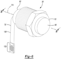
- a second configuration of a dipstick assembly 26' is shown.
- the dipstick assembly 26 may facilitate inspection of the level of lubricant 48 in a portion of the housing assembly 20, such as the sump portion 46, as previously discussed.
- the entire dipstick assembly 26' may be removably mounted to the housing assembly 20 rather than a portion of the dipstick assembly as in the dipstick assembly 26 previously described in which the fitting 70 remains mounted to the housing assembly 20.
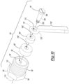
- the dipstick assembly 26' may include a fitting 70', a sleeve 74', and a dipstick 78'.
- the dipstick assembly 26' may include a magnet 80'.
- the fitting 70' may be removably mountable to the housing assembly 20.
- the fitting 70' may have a first end 90', a second end 92', a fitting hole 94', a mounting portion 96', and a tool engagement portion 98'.
- the first end 90' may face away from the housing assembly 20.
- the first end 90' may also be disposed outside of the housing assembly 20.
- the second end 92' may be disposed opposite the first end 90'.
- the second end 92' may be disposed inside the housing assembly 20 or its mounting hole 34.
- the fitting hole 94' may be defined by the fitting 70.
- the fitting hole 94' may be a blind hole that may extend from the second end 92' toward the first end 90'.
- the fitting hole 94' may extend along the axis 110.
- the mounting portion 96' may facilitate mounting of the fitting 70' to the housing assembly 20.
- the mounting portion 96' is threaded and is configured to mate with a corresponding thread in the mounting hole 34.
- the tool engagement portion 98' may be axially positioned between the first end 90' and the second end 92'.
- the tool engagement portion 98' may be axially positioned between the first and 90' end the mounting portion 96'.
- the tool engagement portion 98' may be disposed outside of the housing assembly 20 and may include one or more flat surfaces that may be engageable with a tool, such as a socket or a wrench, to facilitate installation of the fitting 70' on the housing assembly 20.
- the sleeve 74' may be fixedly mounted to the fitting 70'. For instance, the sleeve 74' may be partially received in the fitting hole 94' with an interference fit. In at least one configuration, the sleeve 74' may define a sleeve hole 170' and may have a sleeve flange 172'.
- the sleeve hole 170' may be a through hole that may extend through the sleeve 74'.
- the dipstick 78' may extend through the sleeve hole 170'.
- the sleeve flange 172' may be disposed at an end of the sleeve 74'.
- the sleeve flange 172' may extend away from the axis 110.
- the sleeve flange 172' may extend away from the axis 110 and may engage the magnet 80' to inhibit axial movement of the magnet 80'.
- the dipstick 78' may facilitate measurement of the level of the lubricant 48 in the housing assembly 20.
- the dipstick 78' may be configured as a thin rod, wire, or other member that may be mounted to the fitting 70' in the fitting hole 94'.
- the dipstick 78' may not engage the fitting 70' in one or more embodiments.
- the dipstick 78' may have a nonlinear configuration that may allow the dipstick 78' to be located in close proximity to an inner side of the housing assembly 20.
- the dipstick 78' may be installable in regions where there is limited space between the housing assembly 20 and internal components such as the differential assembly 22.
- the dipstick 78' may not contact moving components inside of the housing assembly 20 like the differential assembly 22 and the axle shafts 24 when the fitting 70' is received in the mounting hole 34.
- the dipstick 78' may be rotatably mounted to the fitting 70'.
- the dipstick 78' may be rotatable about the axis 110 independent of the fitting 70'.
- the dipstick 78' may not rotate with the fitting 70' when the fitting 70' is rotated about the axis 110 to install or remove the fitting 70' from the mounting hole 34.
- the dipstick 78' may be free to rotate and may extend downward due to the force of gravity to a location where lubricant 48 may collect, such as the sump portion 46.
- the dipstick 78' may be self-orienting in a manner that facilitates the detection of the level of lubricant 48.
- the dipstick 78' may include a first end portion 130' and a second end portion 132'.
- the dipstick 78' may also include a first intermediate portion 134' and a second intermediate portion 136'.
- the first end portion 130' may facilitate mounting of the dipstick 78' to the fitting 70'.
- the first end portion 130' may be rotatably received in the fitting hole 94'.
- the first end portion 130 may be disposed along the axis 110.
- the first end portion 130' may include a retaining feature 180'.
- the retaining feature 180' may be received in the fitting hole 94' and may be spaced apart from the fitting 70'.
- the retaining feature 180' may inhibit removal of the dipstick 78' from the sleeve 74'.
- the retaining feature 180' may extend away from the axis 110 and may engage an end of the sleeve 74' that is located inside the fitting hole 94' to limit axial movement of the dipstick 78' toward the sleeve flange 172' and prevent removal of the dipstick 78' from the sleeve 74'.
- the second end portion 132' may be disposed opposite the first end portion 130'. As such, the second end portion 132' may be disposed at a distal end or a free end of the dipstick 78'. The second end portion 132' may be at least partially receivable in the lubricant 48 that collects in the housing assembly 20.
- the second end portion 132' may also be configured to facilitate measurement of the amount of lubricant 48 or lubricant fill level in the housing assembly 20.
- the second end portion 132' may include one or more markings that may designate a maximum lubricant fill level, a minimum lubricant fill level, or both. Such markings may have any suitable configuration. For instance a marking may be configured as a line, notch, groove, protrusion, or the like as previously discussed.
- the first intermediate portion 134' may extend from the first end portion 130' in an axial direction to the second intermediate portion 136'.
- the first intermediate portion 134' may be at least partially received in the fitting hole 94' and the sleeve hole 170' and may extend along the axis 110.
- the second intermediate portion 136' may extend from the first intermediate portion 134' to the second end portion 132'.
- the second intermediate portion 136' may be disposed outside of the fitting hole 94' when the fitting 70' is mounted to the housing assembly 20.
- the second intermediate portion 136' may be disposed substantially perpendicular to the axis 110. As such, the second intermediate portion 136' may extend vertically downward, which may facilitate the detection of the level of lubricant 48 in the sump portion 46.
- the magnet 80' may be disposed proximate the second end 92' of the fitting 70'.
- the magnet 80' or a portion thereof may be received in the housing assembly 20.
- the magnet 80' engages the second end 92' of the fitting 70' and is received in the cavity 44.
- the magnet 80' may be configured as a ring that may extend around the axis 110 and that may define a magnet hole 160' through which the sleeve 74' and the dipstick 78' may extend.
- the magnet 80' may attract and retain metal particulates and may be inspected as previously described.
- the dipstick assembly 26' may be removed from the housing assembly 20 by rotating the fitting 70' about the axis 110 in a first rotational direction. Once the fitting 70' has been released from the housing assembly 20, the fitting 70' and dipstick 78' may then be maneuvered to remove the dipstick 78' through the mounting hole 34. The dipstick 78' may then be inspected to determine the level of lubricant 48 as previously discussed. The dipstick assembly 26' may then be reinstalled by inserting the dipstick 78' through the mounting hole 34, engaging the mounting portion 96' with the thread of the mounting hole 34, and rotating the fitting 70' in a second rotational direction to secure the fitting 70' to the housing assembly 20.
- a third configuration of a dipstick assembly 26" is shown.
- the entire dipstick assembly 26" may be removably mountable to the housing assembly 20 like the dipstick assembly 26' previously described.
- the dipstick assembly 26" may include a fitting 70", a fastener 76", and a dipstick 78".
- the dipstick assembly 26" may also include a magnet 80", a spacer 86", or both.
- the fitting 70" may be removably mountable to the housing assembly 20 and may be similar to the fitting 70' previously described.
- the fitting 70" may have a first end 90', a second end 92', a fitting hole 94', a mounting portion 96', and a tool engagement portion 98'.
- the fitting hole 94' may be a blind hole that may extend along the axis 110 from the second end 92' toward the first end 90' as previously described.
- the fitting hole 94' may be threaded.
- the fastener 76" may extend along the axis 110.
- the fastener 76" may be fixedly coupled to the fitting 70" such that the fastener 76" may not rotate with respect to the fitting 70".
- the fastener 76" may be partially received in the fitting hole 94' and may have any suitable configuration. In at least one configuration, the fastener 76" may have a shank 200, a threaded portion 202, and an enlarged head 204.
- the shank 200 may be disposed along the axis 110.
- the shank 200 may have any suitable configuration.
- the shank 200 may have a cylindrical configuration that may be centered about the axis 110.
- the shank 200 may have a larger diameter than the threaded portion 202.
- the threaded portion 202 may extend from the shank 200.
- the threaded portion 202 may be received in the fitting hole 94' and may mate with the thread of the fitting hole 94'.
- the enlarged head 204 may extend from the shank 200 and may be disposed at an end of the shank 200 opposite the threaded portion 202.
- the enlarged head 204 may have a larger diameter than the shank 200 to limit axial movement of the dipstick 78".
- the dipstick 78" may facilitate measurement of the level of lubricant 48 in the housing assembly 20 as previously described.
- the dipstick 78" may be spaced apart from and may not contact the fitting 70", the magnet 80", or moving components inside of the housing assembly 20, such as the differential assembly 22 and the axle shafts 24, when the fitting 70" is received in the mounting hole 34.
- the dipstick 78" may be rotatably mounted to the fitting 70" such that the dipstick 78" is rotatable about the axis 110 independent of the fitting 70". As such, the dipstick 78" may not rotate with the fitting 70" when the fitting 70" is rotated about the axis 110 to install or remove the fitting 70" from the mounting hole 34. Instead, the dipstick 78" may be free to rotate and may extend downward under the force of gravity to a location where lubricant 48 may collect, such as the sump portion 46. As such, the dipstick 78" may be self-orienting in a manner that facilitates the detection of the level of lubricant 48. In the configuration shown, the dipstick 78" has a cylindrical cross-section although other cross-sectional shapes are contemplated. In at least one embodiment, the dipstick 78" may include a first end portion 130" and a second end portion 132".
- the first end portion 130" may facilitate mounting of the dipstick 78" to the fastener 76".
- the first end portion 130" may define a dipstick hole 210 through which the fastener 76" may extend.
- the first end portion 130" of the dipstick 78" may extend at least partially around the shank 200 of the fastener 76".
- the dipstick hole 210 may be slightly larger than the shank 200 to permit the dipstick 78" to rotate about the shank 200.
- the dipstick hole 210 may extend partially or completely around the fastener 76".
- the dipstick hole 210 may extend partially around the fastener 76" by forming the dipstick 78" around a die or mandrel such that the dipstick 78" does not extend continuously around the axis 110.
- the second end portion 132" may extend from the first end portion 130" and may include a distal end or a free end of the dipstick 78".
- the second end portion 132" may be at least partially receivable in the lubricant 48 that collects in the housing assembly 20.
- the second end portion 132" may also be configured to facilitate measurement of the amount of lubricant 48 or lubricant fill level in the housing assembly 20.
- the second end portion 132" may include one or more markings that may designate a maximum lubricant fill level, a minimum lubricant fill level, or both. Such markings may have any suitable configuration as previously described.
- the magnet 80" may be disposed on the fitting 70".
- the magnet 80" may extend around the axis 110 and may define a magnet hole 160".
- the magnet 80" may be disposed proximate the second end 92' of the fitting 70".
- the magnet 80" or a portion thereof may be received in the housing assembly 20. In the configuration shown, the magnet 80" engages the second end 92" of the fitting 70" and is partially received in the cavity 44.
- the magnet 80" may be configured as a ring that may extend around the axis 110 and that may define a magnet hole 160" through which the fastener 76" may extend.
- the dipstick 78" may not extend through the magnet hole 160".
- the magnet 80" may attract and retain metal particulates and may be inspected as previously described.
- the magnet 80" may be attached to the fitting 70" in any suitable manner, such as with an adhesive, fastener, magnetically, or combinations thereof.
- the spacer 86 may be axially positioned between the dipstick 78" and the magnet 80".
- the spacer 86" may have a spacer hole 190" through which the fastener 76" may extend.
- the spacer 86" may separate the dipstick 78" from the magnet 80".
- Such separation may help maintain rotatability of a dipstick 78", such as when the dipstick 78" is made of a ferrous material.
- the spacer 86" may separate the dipstick 78" from the magnet 80" so that the dipstick 78" may not be directly or indirectly magnetically attached to the magnet 80" in a manner that prevents rotation of the dipstick 78" about the axis 110.
- dipstick assembly 26' is shown.
- This configuration may be substantially the same as the configuration shown in Figures 9-11 except for the configuration of the dipstick 78'''.
- the dipstick 78"' defines a dipstick hole 210 that extends continuously around the fastener 76" rather than partially around the fastener 76".
- the dipstick 78′′′ or a portion thereof may have a non-cylindrical cross-section.
- the dipstick 78" may be a stamped part in which the first end portion 130" and the second end portion 132" have generally flat or planar opposing surfaces.
- the portion of the dipstick 78′′′ that interconnects the first end portion 130" and the second end portion 132" may also be flattened or may have a different cross-sectional shape.
- axle assembly and dipstick assemblies described above may allow the level of lubricant within an axle housing to be more accurately assessed as compared to other techniques in which a predetermined amount of lubricant is added but not subsequently measured (e.g., the lubricant level is subjectively evaluated rather than quantitatively measured).
- a more accurate assessment of the lubricant level in an axle housing may allow an axle assembly to be specified with or filled to a lower lubricant fill level, which may reduce lubricant drag or churning losses when the differential assembly rotates, may increase operating efficiency of the axle assembly, and may reduce vehicle fuel consumption.
- the dipstick assembly may allow the lubricant level to be checked without specialized tools.
- more accurate assessment of lubricant levels may avoid under filling an axle assembly with lubricant, which may not only help ensure that an appropriate amount of lubricant is inside the axle assembly, but may also help reduce warranty costs incurred by vehicle manufacturers due to a vehicle dealer subjectively and incorrectly determining that an axle assembly was underfilled during a pre-sale inspection and then unnecessarily adding lubricant to the axle assembly and charging the associated labor and materials to the vehicle manufacturer.
Landscapes
- Engineering & Computer Science (AREA)
- General Engineering & Computer Science (AREA)
- Mechanical Engineering (AREA)
- Physics & Mathematics (AREA)
- Fluid Mechanics (AREA)
- General Physics & Mathematics (AREA)
- General Details Of Gearings (AREA)
- Transmission And Conversion Of Sensor Element Output (AREA)
- Rolling Contact Bearings (AREA)
Abstract
Description
- This disclosure relates to an axle assembly that has dipstick assembly. The dipstick assembly may facilitate measurement of a level of lubricant in a housing assembly.
- An axle assembly having a fill-check assembly is disclosed in
U.S. patent application serial no. 16/659,919 . - In at least one embodiment an axle assembly is provided. The axle assembly may include a housing assembly and a dipstick assembly. The housing assembly may at least partially define a cavity that receives lubricant. The dipstick assembly may include a fitting, a cap, and a dipstick. The fitting may be mounted to the housing assembly and may define a fitting hole that is disposed along an axis. The cap may be removably mountable to the fitting. The dipstick may include a first end portion, a second end portion, a first intermediate portion, and a second intermediate portion. The first end portion may be mounted to the cap. The second end portion may be disposed opposite the first end portion. The first intermediate portion may extend from the first end portion and may be at least partially received in the fitting hole when the cap is mounted to the fitting. The second intermediate portion may extend from the first intermediate portion to the second end portion. The second intermediate portion may be disposed outside of the fitting hole when the cap is mounted to the fitting. The second intermediate portion may be disposed substantially perpendicular to the axis.
- In at least one embodiment an axle assembly is provided. The axle assembly may include a housing assembly and a dipstick assembly. The housing assembly may have a mounting hole and may at least partially define a cavity that receives lubricant. The dipstick assembly may be removably mountable to the housing assembly. The dipstick assembly may include a fitting and a dipstick. The fitting may be removably mountable to the housing assembly, may be receivable in the mounting hole, and may be disposed along an axis. The dipstick may be rotatably mounted to the fitting such that the dipstick is rotatable about the axis independent of the fitting.
-
-
Figure 1 is a perspective view of an example of an axle assembly. -
Figure 2 is an exploded view of a portion of the axle assembly ofFigure 1 . -
Figure 3 is a perspective view of a first embodiment of a dipstick assembly that may be provided with the axle assembly. -
Figure 4 is an exploded view of the dipstick assembly ofFigure 3 . -
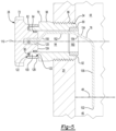
Figure 5 is a section view along section line 5-5 of the dipstick assembly ofFigure 3 installed on the axle assembly. -
Figure 6 is a perspective view of a second embodiment of a dipstick assembly that may be provided with the axle assembly. -
Figure 7 is an exploded view of the dipstick assembly ofFigure 6 . -
Figure 8 is a section view along section line 8-8 of the dipstick assembly ofFigure 6 installed on the axle assembly. -
Figure 9 is a perspective view of a third embodiment of a dipstick assembly that may be provided with the axle assembly. -
Figure 10 is an exploded view of the dipstick assembly ofFigure 9 . -
Figure 11 is a section view along section line 11-11 of the dipstick assembly ofFigure 9 installed on the axle assembly. -
Figure 12 is a perspective view of a fourth embodiment of a dipstick assembly that may be provided with the axle assembly. -
Figure 13 is an exploded view of the dipstick assembly ofFigure 12 . -
Figure 14 is a section view along section line 14-14 of the dipstick assembly ofFigure 12 installed on the axle assembly. - As required, detailed embodiments of the present invention are disclosed herein; however, it is to be understood that the disclosed embodiments are merely exemplary of the invention that may be embodied in various and alternative forms. The figures are not necessarily to scale; some features may be exaggerated or minimized to show details of particular components. Therefore, specific structural and functional details disclosed herein are not to be interpreted as limiting, but merely as a representative basis for teaching one skilled in the art to variously employ the present invention.
- Referring to
Figure 1 , an example of anaxle assembly 10 is shown. Theaxle assembly 10 may be provided with a motor vehicle like a truck, bus, farm equipment, mining equipment, military transport or weaponry vehicle, or cargo loading equipment for land, air, or marine vessels. The motor vehicle may include a trailer for transporting cargo in one or more embodiments. - The
axle assembly 10 may provide torque to one or more traction wheel assemblies that may include a tire mounted on a wheel. The wheel may be mounted to a wheel hub that may be rotatable about a wheel axis. - One or more axle assemblies may be provided with the vehicle. As is best shown with reference to
Figures 1 and2 , theaxle assembly 10 may include ahousing assembly 20, a differential assembly 22, at least oneaxle shaft 24, and adipstick assembly 26. - Referring primarily to
Figure 2 , thehousing assembly 20 may receive various components of theaxle assembly 10. In addition, thehousing assembly 20 may facilitate mounting of theaxle assembly 10 to the vehicle. In at least one configuration, thehousing assembly 20 may include anaxle housing 30, adifferential carrier 32, and amounting hole 34. - The
axle housing 30 may receive and may support theaxle shafts 24, which are best shown inFigure 1 . In at least one configuration, theaxle housing 30 may include acenter portion 40 and at least onearm portion 42. - The
center portion 40 may be disposed proximate the center of theaxle housing 30. Thecenter portion 40 may at least partially define acavity 44 that may at least partially receive the differential assembly 22. As is best shown inFigure 2 , a lower region of thecenter portion 40 and thecavity 44 may at least partially define asump portion 46 that may contain or collectlubricant 48. Thelubricant 48 may be a lubricating fluid such as oil.Lubricant 48 in thesump portion 46 may be splashed by a ring gear of the differential assembly 22 and distributed to lubricate various components when the differential assembly 22 rotates.Lubricant 48 may collect in thesump portion 46 and increase the level oflubricant 48 in thesump portion 46 when the differential assembly 22 does not rotate. InFigure 2 , thecenter portion 40 is illustrated with a bowl cover exploded from theaxle housing 30 to better show features inside theaxle housing 30; however, it is contemplated that the bowl cover or a portion thereof may be integrally formed with one or more components that make up theaxle housing 30 and may not be removable in the manner shown. - The
cavity 44 will be primarily described in the context as being the cavity that includes thesump portion 46; however, it is contemplated that thecavity 44 may be provided in different locations, such as in anarm portion 42 of thehousing assembly 20 when thearm portion 42 is configured to collectlubricant 48 or function as a lubricant reservoir. - Referring to
Figure 2 , thecenter portion 40 may facilitate mounting of thedifferential carrier 32 to theaxle housing 30. For example, thecenter portion 40 may have a set of holes that may be aligned with corresponding holes on thedifferential carrier 32. Each hole may receive a fastener, such as a bolt, that may couple thedifferential carrier 32 to theaxle housing 30. - Referring to
Figures 1 and2 , one ormore arm portions 42 may extend from thecenter portion 40. For example, twoarm portions 42 may extend in opposite directions from thecenter portion 40 and away from the differential assembly 22. Thearm portions 42 may have substantially similar configurations. For example, thearm portions 42 may each have a hollow configuration or tubular configuration that may extend around and may receive acorresponding axle shaft 24 and may help separate or isolate theaxle shaft 24 or a portion thereof from the surrounding environment. Anarm portion 42 or a portion thereof may or may not be integrally formed with thecenter portion 40. It is also contemplated that thearm portions 42 may be omitted. - Referring to
Figures 1 and2 , thedifferential carrier 32 may be mounted to thecenter portion 40 of theaxle housing 30. Thedifferential carrier 32 may support the differential assembly 22. For example, thedifferential carrier 32 may include one or more bearing supports 50 that may support a roller bearing assembly that may rotatably support the differential assembly 22. - Referring to
Figure 2 , the mountinghole 34 may be a through hole that extends through a wall of thehousing assembly 20. The mountinghole 34 may be provided in any suitable location. For instance, the mountinghole 34 may be provided in theaxle housing 30, thedifferential carrier 32, or both. The mountinghole 34 may be positioned above a maximum lubricant fill level of theaxle assembly 10 so that the free end of the dipstick of thedipstick assembly 26 may extend downward toward thelubricant 48 and so thatlubricant 48 may not drain out of thehousing assembly 20 via the mountinghole 34 when the vehicle is positioned upright on a substantially level or substantially horizontal surface. - The differential assembly 22 may be at least partially received in the
center portion 40 of thehousing assembly 20. The differential assembly 22 may be rotatable about adifferential axis 60 and may transmit torque to its associated traction wheel assemblies via theaxle shafts 24. The differential assembly 22 may be operatively connected to theaxle shafts 24 and may permit theaxle shafts 24 to rotate at different rotational speeds in a manner known by those skilled in the art. The differential assembly 22 may have a ring gear 62 that may have teeth the mate or mesh with the teeth of a gear portion of a drive pinion that may be operatively connected to a power source. The ring gear 62 may be fixedly disposed on a differential case of the differential assembly 22 such that the differential case and ring gear 62 may be rotatable together about thedifferential axis 60. A differential gear set of the differential assembly 22 may transmit torque to theaxle shafts 24 in a manner known by those skilled in the art. Accordingly, the differential assembly 22 may receive torque from the drive pinion via the ring gear 62 and transmit torque to theaxle shafts 24. - The power source may be of any suitable type. For instance, the power source may be an electrical power source or a non-electrical power source. An example of an electrical power source is an electrical machine like an electric motor. An example of a non-electrical power source is an internal combustion engine. The power source may be configured as an electric motor that is provided with the
axle assembly 10; however, it is contemplated that the power source, whether electrical or non-electrical, may not be provided with theaxle assembly 10. For instance, the power source may be located remotely from theaxle assembly 10 and may be operatively connected to theaxle assembly 10 via a linkage like a shaft. - Referring to
Figure 1 , theaxle shafts 24 may transmit torque from the differential assembly 22 to corresponding wheel hubs and wheels. Twoaxle shafts 24 may be provided such that eachaxle shaft 24 extends through adifferent arm portion 42 ofaxle housing 30. Theaxle shafts 24 may extend along and may be rotatable about an axis, such as thedifferential axis 60. Eachaxle shaft 24 may have a first end and a second end. The first end may be operatively connected to the differential assembly 22. The second end may be disposed opposite the first end and may be operatively connected to a wheel. Optionally, gear reduction may be provided between anaxle shaft 24 and a wheel. - Referring to
Figures 3-5 , a first configuration of adipstick assembly 26 is shown. Thedipstick assembly 26 may facilitate inspection of the level oflubricant 48 in a portion of thehousing assembly 20, such as thesump portion 46. In at least one configuration, thedipstick assembly 26 may include a fitting 70, acap 72, and adipstick 78. Thedipstick assembly 26 may also include amagnet 80, a biasingmember 82, aseal 84, or combinations thereof. - The fitting 70 may be mounted to the
housing assembly 20. For instance, the fitting may be partially received inside the mountinghole 34 of thehousing assembly 20. In at least one configuration, the fitting 70 may have afirst end 90, asecond end 92, afitting hole 94, a mountingportion 96, and atool engagement portion 98. The fitting 70 may also include a mountingring 100, arecess 104, aprotrusion 102, or combinations thereof. - Referring primarily to
Figures 4 and5 , thefirst end 90 may face away from thehousing assembly 20. Thefirst end 90 may also be disposed outside of thehousing assembly 20. - The
second end 92 may be disposed opposite thefirst end 90. Thesecond end 92 may be disposed inside thehousing assembly 20 or its mountinghole 34. - The
fitting hole 94 may be defined by the fitting 70. Thefitting hole 94 may be a through hole that may extend from thefirst end 90 to thesecond end 92. Thefitting hole 94 may extend along anaxis 110. In at least one embodiment, theaxis 110 may extend in a horizontal or have substantially horizontal direction rather than in a vertical or substantially vertical direction as may be associated with a dipstick for measuring the oil level in an internal combustion engine. - The mounting
portion 96 may facilitate mounting of the fitting 70 to thehousing assembly 20. In the configuration shown, the mountingportion 96 is threaded and is configured to mate with a corresponding thread in the mountinghole 34. Alternatively, the mountingportion 96 may not be threaded and may be attached to thehousing assembly 20 in another manner, including but not limited to an interference fit, or with a weld, adhesive, or the like. - The
tool engagement portion 98 may be axially positioned between thefirst end 90 and thesecond end 92. For instance, thetool engagement portion 98 may be axially positioned between the mountingportion 96 and the mountingring 100. Thetool engagement portion 98 may be disposed outside of thehousing assembly 20. In at least one configuration, thetool engagement portion 98 may include one or more flat surfaces that may be engageable with a tool, such as a socket or a wrench, to facilitate installation of the fitting 70 on thehousing assembly 20. - The mounting
ring 100 may facilitate mounting of thecap 72. The mountingring 100 may be disposed outside of thehousing assembly 20. The mountingring 100 may extend in an axial direction from thefirst end 90 toward thesecond end 92. In addition, the mountingring 100 may extend continuously around theaxis 110. - Referring to
Figure 4 , theprotrusion 102 may be disposed outside of thehousing assembly 20. As such, theprotrusion 102 may be disposed outside of thecavity 44. Theprotrusion 102 may extend from the mountingring 100 in a direction that may extend away from theaxis 110. Theprotrusion 102 may have an enlarged head disposed at its distal end. - Referring primarily to
Figure 4 , therecess 104 may be configured to receive and position themagnet 80. Therecess 104 may extend from thesecond end 92 toward thefirst end 90. In addition, therecess 104 may extend radially outward from thefitting hole 94 toward the mountingportion 96 such that therecess 104 may have a larger diameter than thefitting hole 94. - Referring to
Figures 4 and5 , thecap 72 may be removably mountable to the fitting 70. Thecap 72 may be disposed outside of thehousing assembly 20 and may facilitate installation and removal of thedipstick 78 as will be described in more detail below. In at least one configuration, thecap 72 may define a mountingfeature 120. Thecap 72 may also include agroove 122, aninner ring 124, anouter ring 126, aslot 128, or combinations thereof. - The mounting
feature 120 may facilitate mounting of thedipstick 78 to thecap 72. The mountingfeature 120 may have a male configuration, a female configuration, or combinations thereof. In the configuration shown, the mountingfeature 120 has a female configuration and is configured as a blind hole. The mountingfeature 120 may be disposed along theaxis 110 and may receive an end of thedipstick 78. - The
groove 122 may be spaced apart from and may extend around the mountingfeature 120. Thegroove 122 may receive the mountingring 100 of the fitting 70 when thecap 72 is mounted to the fitting 70. Thegroove 122 may be defined by theinner ring 124, theouter ring 126, or both. - The
inner ring 124 may be radially positioned between the mountingfeature 120 and thegroove 122. Theinner ring 124 may be received inside thefitting hole 94 when thecap 72 is mounted to the fitting 70. In at least one configuration, theinner ring 124 may include a seal groove that may receive theseal 84. - The
outer ring 126 may extend around the mountingring 100 of the fitting 70. In addition, theouter ring 126 may extend around theinner ring 124, if provided, and theaxis 110. - Referring to
Figures 3 and4 , theslot 128 may be configured to receive theprotrusion 102 on the fitting 70 to inhibit removal of thecap 72. Theslot 128 may extend through theouter ring 126 and may have a generally L-shaped configuration that may extend from an open end to a closed end. The open end may face toward the fitting 70. Theslot 128 may extend axially from the open end in a direction that extends away from the fitting 70 to a bend. Theslot 128 may change direction at the bend and may extend in a circumferential direction around theouter ring 126 to the closed end. Theprotrusion 102 and theslot 128 may cooperate to secure the cap. For instance, thecap 72 and the fitting 70 may be axially aligned such that theinner ring 124 may be axially insertable into thefitting hole 94. In addition, thecap 72 and the fitting 70 may be rotationally aligned about theaxis 110 such that the open end of theslot 128 may be aligned with theprotrusion 102. Thecap 72 may then be moved along theaxis 110 toward the fitting 70 so that theslot 128 receives theprotrusion 102 and theprotrusion 102 is disposed proximate the bend. Then thecap 72 may be rotated about theaxis 110 such that the closed end of theslot 128 moves toward and is disposed proximate theprotrusion 102, thereby limiting axial movement and removal of thecap 72. Theprotrusion 102 and theslot 128 may cooperate to set a rotational position of thecap 72 about theaxis 110 in which thedipstick 78 may extend downward or toward a location wherelubricant 48 collects inside thehousing assembly 20 when theprotrusion 102 is received in theslot 128. Thecap 72 may be removed by rotating thecap 72 about theaxis 110 so that the bend is disposed adjacent to theprotrusion 102 and then thecap 72 may be moved along theaxis 110 away from the fitting 70 to remove thecap 72. Thecap 72 may then be maneuvered to allow thedipstick 78 to be removed from thefitting hole 94 to permit visual inspection of the level of lubricant proximate the free end of thedipstick 78. - Referring to
Figures 3-5 , thedipstick 78 may facilitate measurement of the level of thelubricant 48 in thehousing assembly 20. Thedipstick 78 may be configured as a thin rod, wire or other member that may be mounted to thecap 72 and that may be inserted through thefitting hole 94 of the fitting 70 to measure level oflubricant 48. Thedipstick 78 may not engage the fitting 70 when thecap 72 is mounted to the fitting 70 and thedipstick 78 is disposed in thehousing assembly 20 and thefitting hole 94. In at least one configuration, thedipstick 78 may have a nonlinear configuration that may allow thedipstick 78 to be located in close proximity to an inner side of thehousing assembly 20. As such, thedipstick 78 may be installable in regions where there is limited space between thehousing assembly 20 and internal components, such as the differential assembly 22. Moreover, thedipstick 78 may not contact moving components inside of the housing assembly like the differential assembly 22 and theaxle shafts 24 when thecap 72 is mounted to the fitting 70. In at least one embodiment, thedipstick 78 may include afirst end portion 130 and asecond end portion 132. Thedipstick 78 may also include a firstintermediate portion 134 and a secondintermediate portion 136. - The
first end portion 130 may facilitate mounting of thedipstick 78 to thecap 72. For instance, thefirst end portion 130 may be mounted to or received in the mountingfeature 120 of thecap 72. In at least one configuration, thefirst end portion 130 may be disposed along theaxis 110. - The
second end portion 132 may be disposed opposite thefirst end portion 130. As such, thesecond end portion 132 may be disposed at a distal end or a free end of thedipstick 78. Thesecond end portion 132 may be at least partially receivable in thelubricant 48 that collects in thehousing assembly 20. Thesecond end portion 132 may also be configured to facilitate measurement of the amount oflubricant 48 or lubricant fill level in thehousing assembly 20. For instance, thesecond end portion 132 may include one or more markings that may designate a maximum lubricant fill level, a minimum lubricant fill level, or both. Such markings may have any suitable configuration. For instance, a marking may be configured as a line, notch, groove, protrusion, or the like. In the configuration illustrated inFigure 3 , the maximum and minimum fill levels are designated withnotches 140 that are provided along a vertically extending side of thedipstick 78; however, the notches may be omitted or supplemented with other markings, such as those depicted in the other dipstick configurations described below. - Referring primarily to
Figures 4 and5 , the firstintermediate portion 134 may extend from thefirst end portion 130. For instance, the firstintermediate portion 134 may extend from thefirst end portion 130 in an axial direction to the secondintermediate portion 136. The firstintermediate portion 134 may be at least partially received in thefitting hole 94 when thecap 72 mounted to the fitting 70. In at least one configuration, the firstintermediate portion 134 may include afirst segment 150, asecond segment 152, and athird segment 154. - The
first segment 150 may extend from thefirst end portion 130 and may be received in thefitting hole 94 when thecap 72 is installed on the fitting 70. Thefirst segment 150 may be disposed in a nonparallel and non-perpendicular relationship with theaxis 110. For instance, thefirst segment 150 may extend at an angle from thefirst end portion 130 such that thefirst segment 150 extends in an upward direction and away from theaxis 110. - The
second segment 152 may extend from an end of thefirst segment 150 and may be received in thefitting hole 94 when thecap 72 is installed on the fitting 70. In at least one configuration, thesecond segment 152 may be offset from theaxis 110 and may not intersect theaxis 110. In addition, thesecond segment 152 may be disposed substantially parallel to theaxis 110. - The
third segment 154 may extend from an end of thesecond segment 152 to the secondintermediate portion 136. At least a portion of thethird segment 154 may not be received in thefitting hole 94 when thecap 72 is installed on the fitting 70. Thethird segment 154 may be disposed in a nonparallel and non-perpendicular relationship with theaxis 110. For instance, thethird segment 154 may extend at an angle from thesecond segment 152 such that thethird segment 154 extends in a downward direction toward theaxis 110. - The second
intermediate portion 136 may extend from the firstintermediate portion 134 to thesecond end portion 132. The secondintermediate portion 136 may be disposed outside of thefitting hole 94 when thecap 72 is mounted to the fitting 70. In addition, the secondintermediate portion 136 may be disposed substantially perpendicular to theaxis 110. As such, the secondintermediate portion 136 may extend vertically downward, which may facilitate the detection of the level oflubricant 48 in thesump portion 46. - The
magnet 80 may be disposed proximate thesecond end 92 of the fitting 70. Themagnet 80 or a portion thereof may be received in thehousing assembly 20,fitting hole 94, or combinations thereof. In the configuration shown, themagnet 80 is partially received in therecess 104 of the fitting 70 and partially protrudes from the fitting 70 into thecavity 44. In at least one configuration, themagnet 80 may be configured as a ring that may extend around theaxis 110 and that may define amagnet hole 160 through which thedipstick 78 may extend when thecap 72 is mounted to the fitting 70. Themagnet 80 may attract and retain metal particulates that may be transported by thelubricant 48 when thelubricant 48 is splashed or otherwise moves in thehousing assembly 20. As such, themagnet 80 may be inspected to determine if metal particulates are present, which may be indicative of wear of one or more components of theaxle assembly 10. Inspection may include a visual inspection by looking through thefitting hole 94, a tactile inspection by touching themagnet 80, or combinations thereof. - The biasing
member 82 may bias thecap 72 away from the fitting 70 and may inhibit unintentional rotation of thecap 72 about theaxis 110, and hence inhibit unintentional disengagement of theprotrusion 102 from theslot 128 and unintentional removal of thecap 72 from the fitting 70. The biasingmember 82 may have any suitable configuration. For instance, the biasingmember 82 may be configured as a spring, wave washer, or the like. In at least one configuration, the biasingmember 82 may be received in thegroove 122 of thecap 72. - The
seal 84 may inhibitlubricant 48 from passing between the fitting 70 and thecap 72. Theseal 84 may have any suitable configuration. For instance, theseal 84 may be configured as an O-ring that may be received in a seal groove in theinner ring 124 of thecap 72. - Referring to
Figures 6-8 , a second configuration of a dipstick assembly 26' is shown. Thedipstick assembly 26 may facilitate inspection of the level oflubricant 48 in a portion of thehousing assembly 20, such as thesump portion 46, as previously discussed. In this configuration, the entire dipstick assembly 26' may be removably mounted to thehousing assembly 20 rather than a portion of the dipstick assembly as in thedipstick assembly 26 previously described in which the fitting 70 remains mounted to thehousing assembly 20. The dipstick assembly 26' may include a fitting 70', a sleeve 74', and a dipstick 78'. Optionally the dipstick assembly 26' may include a magnet 80'. - The fitting 70' may be removably mountable to the
housing assembly 20. In at least one configuration, the fitting 70' may have a first end 90', a second end 92', afitting hole 94', a mounting portion 96', and a tool engagement portion 98'. - The first end 90' may face away from the
housing assembly 20. The first end 90' may also be disposed outside of thehousing assembly 20. - Referring primarily to
Figures 7 and8 , the second end 92' may be disposed opposite the first end 90'. The second end 92' may be disposed inside thehousing assembly 20 or its mountinghole 34. - The
fitting hole 94' may be defined by the fitting 70. Thefitting hole 94' may be a blind hole that may extend from the second end 92' toward the first end 90'. Thefitting hole 94' may extend along theaxis 110. - The mounting portion 96' may facilitate mounting of the fitting 70' to the
housing assembly 20. In the configuration shown, the mounting portion 96' is threaded and is configured to mate with a corresponding thread in the mountinghole 34. - The tool engagement portion 98' may be axially positioned between the first end 90' and the second end 92'. For instance, the tool engagement portion 98' may be axially positioned between the first and 90' end the mounting portion 96'. The tool engagement portion 98' may be disposed outside of the
housing assembly 20 and may include one or more flat surfaces that may be engageable with a tool, such as a socket or a wrench, to facilitate installation of the fitting 70' on thehousing assembly 20. - The sleeve 74' may be fixedly mounted to the fitting 70'. For instance, the sleeve 74' may be partially received in the
fitting hole 94' with an interference fit. In at least one configuration, the sleeve 74' may define a sleeve hole 170' and may have a sleeve flange 172'. - The sleeve hole 170' may be a through hole that may extend through the sleeve 74'. The dipstick 78' may extend through the sleeve hole 170'.
- The sleeve flange 172' may be disposed at an end of the sleeve 74'. The sleeve flange 172' may extend away from the
axis 110. The sleeve flange 172' may extend away from theaxis 110 and may engage the magnet 80' to inhibit axial movement of the magnet 80'. - The dipstick 78' may facilitate measurement of the level of the
lubricant 48 in thehousing assembly 20. The dipstick 78' may be configured as a thin rod, wire, or other member that may be mounted to the fitting 70' in thefitting hole 94'. The dipstick 78' may not engage the fitting 70' in one or more embodiments. In at least one configuration, the dipstick 78' may have a nonlinear configuration that may allow the dipstick 78' to be located in close proximity to an inner side of thehousing assembly 20. As such, the dipstick 78' may be installable in regions where there is limited space between thehousing assembly 20 and internal components such as the differential assembly 22. Moreover, the dipstick 78' may not contact moving components inside of thehousing assembly 20 like the differential assembly 22 and theaxle shafts 24 when the fitting 70' is received in the mountinghole 34. - The dipstick 78' may be rotatably mounted to the fitting 70'. For instance, the dipstick 78' may be rotatable about the
axis 110 independent of the fitting 70'. As such, the dipstick 78' may not rotate with the fitting 70' when the fitting 70' is rotated about theaxis 110 to install or remove the fitting 70' from the mountinghole 34. Instead, the dipstick 78' may be free to rotate and may extend downward due to the force of gravity to a location wherelubricant 48 may collect, such as thesump portion 46. As such, the dipstick 78' may be self-orienting in a manner that facilitates the detection of the level oflubricant 48. In at least one embodiment, the dipstick 78' may include a first end portion 130' and a second end portion 132'. The dipstick 78' may also include a first intermediate portion 134' and a second intermediate portion 136'. - The first end portion 130' may facilitate mounting of the dipstick 78' to the fitting 70'. For instance, the first end portion 130' may be rotatably received in the
fitting hole 94'. In at least one configuration, thefirst end portion 130 may be disposed along theaxis 110. The first end portion 130' may include a retaining feature 180'. - The retaining feature 180' may be received in the
fitting hole 94' and may be spaced apart from the fitting 70'. The retaining feature 180' may inhibit removal of the dipstick 78' from the sleeve 74'. The retaining feature 180' may extend away from theaxis 110 and may engage an end of the sleeve 74' that is located inside thefitting hole 94' to limit axial movement of the dipstick 78' toward the sleeve flange 172' and prevent removal of the dipstick 78' from the sleeve 74'. - The second end portion 132' may be disposed opposite the first end portion 130'. As such, the second end portion 132' may be disposed at a distal end or a free end of the dipstick 78'. The second end portion 132' may be at least partially receivable in the
lubricant 48 that collects in thehousing assembly 20. The second end portion 132' may also be configured to facilitate measurement of the amount oflubricant 48 or lubricant fill level in thehousing assembly 20. For instance, the second end portion 132' may include one or more markings that may designate a maximum lubricant fill level, a minimum lubricant fill level, or both. Such markings may have any suitable configuration. For instance a marking may be configured as a line, notch, groove, protrusion, or the like as previously discussed. - Referring primarily to
Figure 8 , the first intermediate portion 134' may extend from the first end portion 130' in an axial direction to the second intermediate portion 136'. The first intermediate portion 134' may be at least partially received in thefitting hole 94' and the sleeve hole 170' and may extend along theaxis 110. - The second intermediate portion 136' may extend from the first intermediate portion 134' to the second end portion 132'. The second intermediate portion 136' may be disposed outside of the
fitting hole 94' when the fitting 70' is mounted to thehousing assembly 20. In addition, the second intermediate portion 136' may be disposed substantially perpendicular to theaxis 110. As such, the second intermediate portion 136' may extend vertically downward, which may facilitate the detection of the level oflubricant 48 in thesump portion 46. - The magnet 80' may be disposed proximate the second end 92' of the fitting 70'. The magnet 80' or a portion thereof may be received in the
housing assembly 20. In the configuration shown, the magnet 80' engages the second end 92' of the fitting 70' and is received in thecavity 44. In at least one configuration, the magnet 80' may be configured as a ring that may extend around theaxis 110 and that may define a magnet hole 160' through which the sleeve 74' and the dipstick 78' may extend. The magnet 80' may attract and retain metal particulates and may be inspected as previously described. - The dipstick assembly 26' may be removed from the
housing assembly 20 by rotating the fitting 70' about theaxis 110 in a first rotational direction. Once the fitting 70' has been released from thehousing assembly 20, the fitting 70' and dipstick 78' may then be maneuvered to remove the dipstick 78' through the mountinghole 34. The dipstick 78' may then be inspected to determine the level oflubricant 48 as previously discussed. The dipstick assembly 26' may then be reinstalled by inserting the dipstick 78' through the mountinghole 34, engaging the mounting portion 96' with the thread of the mountinghole 34, and rotating the fitting 70' in a second rotational direction to secure the fitting 70' to thehousing assembly 20. - Referring to
Figures 9-11 , a third configuration of adipstick assembly 26" is shown. In this configuration, theentire dipstick assembly 26" may be removably mountable to thehousing assembly 20 like the dipstick assembly 26' previously described. Thedipstick assembly 26" may include a fitting 70", afastener 76", and adipstick 78". Optionally, thedipstick assembly 26" may also include amagnet 80", aspacer 86", or both. - Referring primarily to
Figures 10 and11 , the fitting 70" may be removably mountable to thehousing assembly 20 and may be similar to the fitting 70' previously described. For example, the fitting 70" may have a first end 90', a second end 92', afitting hole 94', a mounting portion 96', and a tool engagement portion 98'. Thefitting hole 94' may be a blind hole that may extend along theaxis 110 from the second end 92' toward the first end 90' as previously described. Thefitting hole 94' may be threaded. - The
fastener 76" may extend along theaxis 110. Thefastener 76" may be fixedly coupled to the fitting 70" such that thefastener 76" may not rotate with respect to the fitting 70". Thefastener 76" may be partially received in thefitting hole 94' and may have any suitable configuration. In at least one configuration, thefastener 76" may have ashank 200, a threadedportion 202, and anenlarged head 204. - The
shank 200 may be disposed along theaxis 110. Theshank 200 may have any suitable configuration. For instance theshank 200 may have a cylindrical configuration that may be centered about theaxis 110. Theshank 200 may have a larger diameter than the threadedportion 202. - The threaded
portion 202 may extend from theshank 200. The threadedportion 202 may be received in thefitting hole 94' and may mate with the thread of thefitting hole 94'. - The
enlarged head 204 may extend from theshank 200 and may be disposed at an end of theshank 200 opposite the threadedportion 202. Theenlarged head 204 may have a larger diameter than theshank 200 to limit axial movement of thedipstick 78". - The
dipstick 78" may facilitate measurement of the level oflubricant 48 in thehousing assembly 20 as previously described. Thedipstick 78" may be spaced apart from and may not contact the fitting 70", themagnet 80", or moving components inside of thehousing assembly 20, such as the differential assembly 22 and theaxle shafts 24, when the fitting 70" is received in the mountinghole 34. - The
dipstick 78" may be rotatably mounted to the fitting 70" such that thedipstick 78" is rotatable about theaxis 110 independent of the fitting 70". As such, thedipstick 78" may not rotate with the fitting 70" when the fitting 70" is rotated about theaxis 110 to install or remove the fitting 70" from the mountinghole 34. Instead, thedipstick 78" may be free to rotate and may extend downward under the force of gravity to a location wherelubricant 48 may collect, such as thesump portion 46. As such, thedipstick 78" may be self-orienting in a manner that facilitates the detection of the level oflubricant 48. In the configuration shown, thedipstick 78" has a cylindrical cross-section although other cross-sectional shapes are contemplated. In at least one embodiment, thedipstick 78" may include afirst end portion 130" and asecond end portion 132". - The
first end portion 130" may facilitate mounting of thedipstick 78" to thefastener 76". For instance, thefirst end portion 130" may define adipstick hole 210 through which thefastener 76" may extend. As such, thefirst end portion 130" of thedipstick 78" may extend at least partially around theshank 200 of thefastener 76". Thedipstick hole 210 may be slightly larger than theshank 200 to permit thedipstick 78" to rotate about theshank 200. Thedipstick hole 210 may extend partially or completely around thefastener 76". For instance, thedipstick hole 210 may extend partially around thefastener 76" by forming thedipstick 78" around a die or mandrel such that thedipstick 78" does not extend continuously around theaxis 110. - The
second end portion 132" may extend from thefirst end portion 130" and may include a distal end or a free end of thedipstick 78". Thesecond end portion 132" may be at least partially receivable in thelubricant 48 that collects in thehousing assembly 20. Thesecond end portion 132" may also be configured to facilitate measurement of the amount oflubricant 48 or lubricant fill level in thehousing assembly 20. For instance, thesecond end portion 132" may include one or more markings that may designate a maximum lubricant fill level, a minimum lubricant fill level, or both. Such markings may have any suitable configuration as previously described. - The
magnet 80" may be disposed on the fitting 70". Themagnet 80" may extend around theaxis 110 and may define amagnet hole 160". Themagnet 80" may be disposed proximate the second end 92' of the fitting 70". Themagnet 80" or a portion thereof may be received in thehousing assembly 20. In the configuration shown, themagnet 80" engages thesecond end 92" of the fitting 70" and is partially received in thecavity 44. In at least one configuration, themagnet 80" may be configured as a ring that may extend around theaxis 110 and that may define amagnet hole 160" through which thefastener 76" may extend. Thedipstick 78" may not extend through themagnet hole 160". Themagnet 80" may attract and retain metal particulates and may be inspected as previously described. Themagnet 80" may be attached to the fitting 70" in any suitable manner, such as with an adhesive, fastener, magnetically, or combinations thereof. - The
spacer 86", if provided, may be axially positioned between thedipstick 78" and themagnet 80". Thespacer 86" may have aspacer hole 190" through which thefastener 76" may extend. As such, thespacer 86" may separate thedipstick 78" from themagnet 80". Such separation may help maintain rotatability of adipstick 78", such as when thedipstick 78" is made of a ferrous material. For example, thespacer 86" may separate thedipstick 78" from themagnet 80" so that thedipstick 78" may not be directly or indirectly magnetically attached to themagnet 80" in a manner that prevents rotation of thedipstick 78" about theaxis 110. - Referring to
Figures 12-14 , another configuration of a dipstick assembly 26'" is shown. This configuration may be substantially the same as the configuration shown inFigures 9-11 except for the configuration of the dipstick 78'''. In this configuration, thedipstick 78"' defines adipstick hole 210 that extends continuously around thefastener 76" rather than partially around thefastener 76". In addition, thedipstick 78‴ or a portion thereof may have a non-cylindrical cross-section. For instance, thedipstick 78" may be a stamped part in which thefirst end portion 130" and thesecond end portion 132" have generally flat or planar opposing surfaces. The portion of thedipstick 78‴ that interconnects thefirst end portion 130" and thesecond end portion 132" may also be flattened or may have a different cross-sectional shape. - The axle assembly and dipstick assemblies described above may allow the level of lubricant within an axle housing to be more accurately assessed as compared to other techniques in which a predetermined amount of lubricant is added but not subsequently measured (e.g., the lubricant level is subjectively evaluated rather than quantitatively measured). A more accurate assessment of the lubricant level in an axle housing may allow an axle assembly to be specified with or filled to a lower lubricant fill level, which may reduce lubricant drag or churning losses when the differential assembly rotates, may increase operating efficiency of the axle assembly, and may reduce vehicle fuel consumption. The dipstick assembly may allow the lubricant level to be checked without specialized tools. In addition, more accurate assessment of lubricant levels may avoid under filling an axle assembly with lubricant, which may not only help ensure that an appropriate amount of lubricant is inside the axle assembly, but may also help reduce warranty costs incurred by vehicle manufacturers due to a vehicle dealer subjectively and incorrectly determining that an axle assembly was underfilled during a pre-sale inspection and then unnecessarily adding lubricant to the axle assembly and charging the associated labor and materials to the vehicle manufacturer.
- While exemplary embodiments are described above, it is not intended that these embodiments describe all possible forms of the invention. Rather, the words used in the specification are words of description rather than limitation, and it is understood that various changes may be made without departing from the spirit and scope of the invention. Additionally, the features of various implementing embodiments may be combined to form further embodiments of the invention.
Claims (15)
- An axle assembly comprising:a housing assembly that at least partially defines a cavity that receives a lubricant, the housing assembly having a mounting hole; anda dipstick assembly that is removably mountable to the housing assembly, the dipstick assembly including:a fitting that is removably mountable to the housing assembly and is receivable in the mounting hole, the fitting being disposed along an axis; anda dipstick that is rotatably mounted to the fitting such that the dipstick is rotatable about the axis independent of the fitting.
- The axle assembly of claim 1 wherein the dipstick assembly further comprises a magnet that is disposed on the fitting, the magnet extending around the axis and defining a magnet hole through which the dipstick extends when the dipstick assembly is mounted to the housing assembly.
- The axle assembly of any preceding claim wherein the fitting defines a fitting hole that is disposed along the axis and wherein the dipstick is rotatably received in the fitting hole.
- The axle assembly of any preceding claim further comprising a sleeve that is partially received in a fitting hole that is defined by the fitting, the sleeve defining a sleeve hole through which the dipstick extends.
- The axle assembly of claim 3 or claim 4 wherein the dipstick includes a retaining feature that is received in the fitting hole and that inhibits removal of the dipstick from the sleeve.
- The axle assembly of claim 5 wherein the retaining feature extends away from the axis and engages an end of the sleeve to limit axial movement of the dipstick.
- The axle assembly of any one of claims 4 to 6 wherein the dipstick assembly further comprises a magnet that extends around the axis and defines a magnet hole, wherein the sleeve is received in the magnet hole.
- The axle assembly of claim 7 wherein the sleeve has a sleeve flange that extends away from the axis and that engages the magnet to inhibit axial movement of the magnet.
- The axle assembly of any preceding claim further comprising a fastener that couples the dipstick to the fitting, wherein the dipstick is rotatable about the fastener.
- The axle assembly of claim 9 wherein the fastener has a shank, a threaded portion that extends from the shank and that is received in the fitting hole, and an enlarged head that extends from the shank and that is disposed opposite the threaded portion, wherein the dipstick extends at least partially around the shank.
- The axle assembly of claim 9 or claim 10 wherein the dipstick defines a dipstick hole through which the fastener extends.
- The axle assembly of any one of claims 9 to 11 wherein the fastener extends along the axis and is partially received in a fitting hole that is defined by the fitting.
- The axle assembly of any one of claims 9 to 12 wherein the dipstick assembly further comprises a magnet that is disposed on the fitting, the magnet extending around the axis and defining a magnet hole through which the fastener extends.
- The axle assembly of claim 13 wherein the dipstick assembly further comprises a spacer that defines a spacer hole through which the fastener extends, the spacer being axially positioned between the magnet and the dipstick
- The axle assembly of claim 13 or claim 14 wherein the dipstick is spaced apart from and does not contact the fitting or the magnet.
Applications Claiming Priority (2)
| Application Number | Priority Date | Filing Date | Title |
|---|---|---|---|
| US17/197,464 US11396976B1 (en) | 2021-03-10 | 2021-03-10 | Axle assembly having a dipstick assembly |
| EP22158426.1A EP4067835A3 (en) | 2021-03-10 | 2022-02-24 | Axle assembly having a dipstick assembly |
Related Parent Applications (1)
| Application Number | Title | Priority Date | Filing Date |
|---|---|---|---|
| EP22158426.1A Division EP4067835A3 (en) | 2021-03-10 | 2022-02-24 | Axle assembly having a dipstick assembly |
Publications (2)
| Publication Number | Publication Date |
|---|---|
| EP4234897A2 true EP4234897A2 (en) | 2023-08-30 |
| EP4234897A3 EP4234897A3 (en) | 2023-10-04 |
Family
ID=80448486
Family Applications (2)
| Application Number | Title | Priority Date | Filing Date |
|---|---|---|---|
| EP22158426.1A Pending EP4067835A3 (en) | 2021-03-10 | 2022-02-24 | Axle assembly having a dipstick assembly |
| EP23176106.5A Pending EP4234897A3 (en) | 2021-03-10 | 2022-02-24 | Axle assembly having a dipstick assembly |
Family Applications Before (1)
| Application Number | Title | Priority Date | Filing Date |
|---|---|---|---|
| EP22158426.1A Pending EP4067835A3 (en) | 2021-03-10 | 2022-02-24 | Axle assembly having a dipstick assembly |
Country Status (4)
| Country | Link |
|---|---|
| US (2) | US11396976B1 (en) |
| EP (2) | EP4067835A3 (en) |
| CN (1) | CN115071335A (en) |
| BR (1) | BR102022001727A2 (en) |
Families Citing this family (1)
| Publication number | Priority date | Publication date | Assignee | Title |
|---|---|---|---|---|
| DE102018216512A1 (en) * | 2018-09-26 | 2020-03-26 | Bayerische Motoren Werke Aktiengesellschaft | Dipstick, in particular oil dipstick, for an internal combustion engine, in particular a motor vehicle, arrangement of such a dipstick in a guide tube and motor vehicle |
Family Cites Families (10)
| Publication number | Priority date | Publication date | Assignee | Title |
|---|---|---|---|---|
| US2917832A (en) * | 1958-01-17 | 1959-12-22 | Calmenson Benjamin | Dipstick |
| GB1201671A (en) * | 1968-02-05 | 1970-08-12 | Moeller Mfg Co Inc | Oil level testing dip stick closure |
| US3722102A (en) * | 1971-02-24 | 1973-03-27 | Gits Bros Mfg Co | Dip stick |
| JPH0143573Y2 (en) * | 1987-09-11 | 1989-12-18 | ||
| JPH08271316A (en) * | 1995-03-29 | 1996-10-18 | Nissan Diesel Motor Co Ltd | Lubricating oil quantity confirming device in final reduction gear of vehicle |
| US5588502A (en) * | 1995-08-30 | 1996-12-31 | K. J. Manufacturing Co. | Quick connect nipple having a cylindrical magnet |
| US5949317A (en) * | 1998-03-31 | 1999-09-07 | Fink; Randy | Magnetic drain plug |
| US7357225B2 (en) * | 2004-08-05 | 2008-04-15 | Dorian George P | Two part oil or fluid drain plug with magnet |
| US8881421B2 (en) * | 2012-05-18 | 2014-11-11 | Center Manufacturing, Inc. | Dipstick assembly with lock system |
| US9200941B1 (en) * | 2013-03-15 | 2015-12-01 | Justin Kelly | Swiveling check plug for heavy-duty commercial gear system housings |
-
2021
- 2021-03-10 US US17/197,464 patent/US11396976B1/en active Active
- 2021-12-24 CN CN202111599727.2A patent/CN115071335A/en active Pending
-
2022
- 2022-01-31 BR BR102022001727-1A patent/BR102022001727A2/en unknown
- 2022-02-24 EP EP22158426.1A patent/EP4067835A3/en active Pending
- 2022-02-24 EP EP23176106.5A patent/EP4234897A3/en active Pending
- 2022-05-24 US US17/752,365 patent/US11708939B2/en active Active
Also Published As
| Publication number | Publication date |
|---|---|
| EP4234897A3 (en) | 2023-10-04 |
| CN115071335A (en) | 2022-09-20 |
| US11396976B1 (en) | 2022-07-26 |
| US20220290806A1 (en) | 2022-09-15 |
| US11708939B2 (en) | 2023-07-25 |
| EP4067835A3 (en) | 2022-12-14 |
| EP4067835A2 (en) | 2022-10-05 |
| BR102022001727A2 (en) | 2022-09-20 |
Similar Documents
| Publication | Publication Date | Title |
|---|---|---|
| US7503213B2 (en) | Bimetallic sensor mount for axles | |
| CN109944917B (en) | Axle assembly including differential assembly having reverse differential bearings | |
| US20220196129A1 (en) | Axle assembly | |
| US10975945B2 (en) | Axle assembly | |
| US7611435B2 (en) | Power transfer assembly with gasket having magnet | |
| JP5053107B2 (en) | Power transmission device | |
| US8167762B2 (en) | Drive axle assembly with wheel speed measurement system | |
| US11708939B2 (en) | Axle assembly having a dipstick assembly | |
| US9562608B2 (en) | Rotary shaft seal structure for drive system of vehicle | |
| US20180149261A1 (en) | Active oil management system for axles | |
| US20110200282A1 (en) | Vehicle drive unit for dump truck | |
| EP2801737B1 (en) | Axle assembly and method of reworking an axle assembly | |
| CN104819265A (en) | Differential device and method of assembling the same | |
| CN107585022B (en) | Axle assembly with support bearing assembly | |
| US10605349B2 (en) | Lubricant flow regulating system and the axle assembly made therewith | |
| US20110030504A1 (en) | Torque-transmitting device comprising an oil recuperator wiper | |
| CN205078728U (en) | There is automotive gear of oil storage tank on top | |
| US1852226A (en) | Front wheel drive | |
| US10605821B2 (en) | Speed sensor of a vehicle transmission | |
| Chaudhari et al. | Slinger Design in Live 4WD Axle for Tractor | |
| US11079006B2 (en) | Differential unit and differential unit product line | |
| US8021258B2 (en) | Axle assembly having mechanism for circulating lubricating fluid to wheel ends | |
| JPH08270763A (en) | Lubricating structure in terminal reduction gear for vehicle | |
| JP2016011731A (en) | Rotor for detecting vehicle speed | |
| KR20150007673A (en) | Oil gauge of axle hub reduction device |
Legal Events
| Date | Code | Title | Description |
|---|---|---|---|
| PUAI | Public reference made under article 153(3) epc to a published international application that has entered the european phase |
Free format text: ORIGINAL CODE: 0009012 |
|
| STAA | Information on the status of an ep patent application or granted ep patent |
Free format text: STATUS: THE APPLICATION HAS BEEN PUBLISHED |
|
| REG | Reference to a national code |
Ref country code: DE Ref legal event code: R079 Free format text: PREVIOUS MAIN CLASS: F01M0011120000 Ipc: G01F0023040000 |
|
| AC | Divisional application: reference to earlier application |
Ref document number: 4067835 Country of ref document: EP Kind code of ref document: P |
|
| AK | Designated contracting states |
Kind code of ref document: A2 Designated state(s): AL AT BE BG CH CY CZ DE DK EE ES FI FR GB GR HR HU IE IS IT LI LT LU LV MC MK MT NL NO PL PT RO RS SE SI SK SM TR |
|
| PUAL | Search report despatched |
Free format text: ORIGINAL CODE: 0009013 |
|
| AK | Designated contracting states |
Kind code of ref document: A3 Designated state(s): AL AT BE BG CH CY CZ DE DK EE ES FI FR GB GR HR HU IE IS IT LI LT LU LV MC MK MT NL NO PL PT RO RS SE SI SK SM TR |
|
| RIC1 | Information provided on ipc code assigned before grant |
Ipc: F01M 11/04 20060101ALN20230825BHEP Ipc: B03C 1/033 20060101ALN20230825BHEP Ipc: F16N 19/00 20060101ALI20230825BHEP Ipc: F01M 11/12 20060101ALI20230825BHEP Ipc: F16H 57/037 20120101ALI20230825BHEP Ipc: F16H 57/04 20100101ALI20230825BHEP Ipc: B03C 1/28 20060101ALI20230825BHEP Ipc: G01F 23/04 20060101AFI20230825BHEP |
|
| STAA | Information on the status of an ep patent application or granted ep patent |
Free format text: STATUS: REQUEST FOR EXAMINATION WAS MADE |
|
| 17P | Request for examination filed |
Effective date: 20240321 |
|
| RBV | Designated contracting states (corrected) |
Designated state(s): AL AT BE BG CH CY CZ DE DK EE ES FI FR GB GR HR HU IE IS IT LI LT LU LV MC MK MT NL NO PL PT RO RS SE SI SK SM TR |