EP4234894A2 - Wartungsverfahren für turbinenanordnung - Google Patents
Wartungsverfahren für turbinenanordnung Download PDFInfo
- Publication number
- EP4234894A2 EP4234894A2 EP23174180.2A EP23174180A EP4234894A2 EP 4234894 A2 EP4234894 A2 EP 4234894A2 EP 23174180 A EP23174180 A EP 23174180A EP 4234894 A2 EP4234894 A2 EP 4234894A2
- Authority
- EP
- European Patent Office
- Prior art keywords
- damaged region
- repair
- repair tool
- rotor
- camera
- Prior art date
- Legal status (The legal status is an assumption and is not a legal conclusion. Google has not performed a legal analysis and makes no representation as to the accuracy of the status listed.)
- Granted
Links
Images

Classifications
-
- F—MECHANICAL ENGINEERING; LIGHTING; HEATING; WEAPONS; BLASTING
- F01—MACHINES OR ENGINES IN GENERAL; ENGINE PLANTS IN GENERAL; STEAM ENGINES
- F01D—NON-POSITIVE DISPLACEMENT MACHINES OR ENGINES, e.g. STEAM TURBINES
- F01D5/00—Blades; Blade-carrying members; Heating, heat-insulating, cooling or antivibration means on the blades or the members
- F01D5/005—Repairing methods or devices
-
- B—PERFORMING OPERATIONS; TRANSPORTING
- B23—MACHINE TOOLS; METAL-WORKING NOT OTHERWISE PROVIDED FOR
- B23P—METAL-WORKING NOT OTHERWISE PROVIDED FOR; COMBINED OPERATIONS; UNIVERSAL MACHINE TOOLS
- B23P6/00—Restoring or reconditioning objects
- B23P6/002—Repairing turbine components, e.g. moving or stationary blades, rotors
-
- B—PERFORMING OPERATIONS; TRANSPORTING
- B23—MACHINE TOOLS; METAL-WORKING NOT OTHERWISE PROVIDED FOR
- B23P—METAL-WORKING NOT OTHERWISE PROVIDED FOR; COMBINED OPERATIONS; UNIVERSAL MACHINE TOOLS
- B23P6/00—Restoring or reconditioning objects
- B23P6/04—Repairing fractures or cracked metal parts or products, e.g. castings
- B23P6/045—Repairing fractures or cracked metal parts or products, e.g. castings of turbine components, e.g. moving or stationary blades, rotors, etc.
-
- F—MECHANICAL ENGINEERING; LIGHTING; HEATING; WEAPONS; BLASTING
- F01—MACHINES OR ENGINES IN GENERAL; ENGINE PLANTS IN GENERAL; STEAM ENGINES
- F01D—NON-POSITIVE DISPLACEMENT MACHINES OR ENGINES, e.g. STEAM TURBINES
- F01D25/00—Component parts, details, or accessories, not provided for in, or of interest apart from, other groups
- F01D25/28—Supporting or mounting arrangements, e.g. for turbine casing
- F01D25/285—Temporary support structures, e.g. for testing, assembling, installing, repairing; Assembly methods using such structures
-
- F—MECHANICAL ENGINEERING; LIGHTING; HEATING; WEAPONS; BLASTING
- F01—MACHINES OR ENGINES IN GENERAL; ENGINE PLANTS IN GENERAL; STEAM ENGINES
- F01D—NON-POSITIVE DISPLACEMENT MACHINES OR ENGINES, e.g. STEAM TURBINES
- F01D5/00—Blades; Blade-carrying members; Heating, heat-insulating, cooling or antivibration means on the blades or the members
- F01D5/02—Blade-carrying members, e.g. rotors
-
- F—MECHANICAL ENGINEERING; LIGHTING; HEATING; WEAPONS; BLASTING
- F05—INDEXING SCHEMES RELATING TO ENGINES OR PUMPS IN VARIOUS SUBCLASSES OF CLASSES F01-F04
- F05D—INDEXING SCHEME FOR ASPECTS RELATING TO NON-POSITIVE-DISPLACEMENT MACHINES OR ENGINES, GAS-TURBINES OR JET-PROPULSION PLANTS
- F05D2220/00—Application
- F05D2220/30—Application in turbines
- F05D2220/32—Application in turbines in gas turbines
-
- F—MECHANICAL ENGINEERING; LIGHTING; HEATING; WEAPONS; BLASTING
- F05—INDEXING SCHEMES RELATING TO ENGINES OR PUMPS IN VARIOUS SUBCLASSES OF CLASSES F01-F04
- F05D—INDEXING SCHEME FOR ASPECTS RELATING TO NON-POSITIVE-DISPLACEMENT MACHINES OR ENGINES, GAS-TURBINES OR JET-PROPULSION PLANTS
- F05D2230/00—Manufacture
- F05D2230/72—Maintenance
-
- F—MECHANICAL ENGINEERING; LIGHTING; HEATING; WEAPONS; BLASTING
- F05—INDEXING SCHEMES RELATING TO ENGINES OR PUMPS IN VARIOUS SUBCLASSES OF CLASSES F01-F04
- F05D—INDEXING SCHEME FOR ASPECTS RELATING TO NON-POSITIVE-DISPLACEMENT MACHINES OR ENGINES, GAS-TURBINES OR JET-PROPULSION PLANTS
- F05D2230/00—Manufacture
- F05D2230/80—Repairing, retrofitting or upgrading methods
-
- H—ELECTRICITY
- H04—ELECTRIC COMMUNICATION TECHNIQUE
- H04N—PICTORIAL COMMUNICATION, e.g. TELEVISION
- H04N23/00—Cameras or camera modules comprising electronic image sensors; Control thereof
- H04N23/50—Constructional details
- H04N23/555—Constructional details for picking-up images in sites, inaccessible due to their dimensions or hazardous conditions, e.g. endoscopes or borescopes
-
- Y—GENERAL TAGGING OF NEW TECHNOLOGICAL DEVELOPMENTS; GENERAL TAGGING OF CROSS-SECTIONAL TECHNOLOGIES SPANNING OVER SEVERAL SECTIONS OF THE IPC; TECHNICAL SUBJECTS COVERED BY FORMER USPC CROSS-REFERENCE ART COLLECTIONS [XRACs] AND DIGESTS
- Y02—TECHNOLOGIES OR APPLICATIONS FOR MITIGATION OR ADAPTATION AGAINST CLIMATE CHANGE
- Y02T—CLIMATE CHANGE MITIGATION TECHNOLOGIES RELATED TO TRANSPORTATION
- Y02T50/00—Aeronautics or air transport
- Y02T50/60—Efficient propulsion technologies, e.g. for aircraft
Definitions
- the present invention is directed to in situ methods for maintaining turbine assemblies.
- Turbines for aircraft engines as well as gas and steam powered turbines for industrial applications comprise at least one rotor carrying multiple stages of airfoils (henceforth referred to as blades), which rotates with respect to the turbine case.
- the turbine case carries multiple stages of airfoils (henceforth referred to as guide vanes), such that the turbine consists of alternating stages of blades and guide vanes.
- shrouds can be disposed on the radially inner surfaces of the stator so as to form a ring seal around the blade tips.
- blades have platforms and guide vanes have inner sidewalls.
- guide vanes have outer sidewalls to limit radially outward leakage. Together, the blades, guide vanes and shrouds define the primary flowpath inside the turbine.
- the turbine components can experience degradation.
- Periodic inspections such as borescope inspections, are performed in order to assess the condition of the machine in-between service intervals.
- damage that can be observed during inspection include wear (e.g., from incursion of blade tips into the shrouds, particle-induced erosion, water droplet induced erosion, wear due to sliding contact between stationary components), impact (e.g., spallation of thermal or environmental barrier coating ("TBC” or "EBC", respectively) from turbine-section components, leading edge burring/bending of compressor blades), cracking (e.g., thermal fatigue, low-cycle fatigue or high-cycle fatigue), edge-of-contact damage between stationary parts, oxidation or hot corrosion of high-temperature metallic sections, static seal degradation, guide vane sidewall distress, and blade platform distress.
- TBC thermal or environmental barrier coating
- EBC environmental barrier coating
- the turbines are at least partially disassembled to allow repair and/or replacement of damaged components.
- damaged components of turbine engines are primarily repaired at overhaul facilities, with only limited intervention conducted in the field.
- the processes used to repair compressor and turbine flowpath components may include surface cleaning so as to remove accumulated dirt and oxidation products, stripping and restoration of coated surfaces, crack repair, section replacement, aero contouring and smoothing.
- the cost of the unit processes is typically lower than the replacement cost of the damaged components, forced outages are costly and disruptive to the engine operator. Consequently, conventional methods of maintaining turbines using periodic inspections and factory-based component repair methods may sometimes result in unplanned outages caused by a small number of heavily distressed components and will run some fraction of components beyond their repair limits.
- the present invention seeks to provide a novel method of maintaining turbine assemblies which overcomes the above-mentioned problems by using a remotely controlled maintenance apparatus capable of performing repairs.
- One object of the present invention is to provide methods for maintaining turbine assemblies, such as gas turbine engines.
- the maintenance may include inspection of internal parts of a turbine assembly.
- the maintenance may also include repair of damaged internal parts of a turbine assembly, including shrouds, blades and guide vanes.
- the invention is directed to a method for maintenance of a turbine assembly, the turbine assembly including a rotor and a stator, the stator including a damaged region, the method including: disposing a remotely controllable maintenance apparatus on the rotor; positioning the maintenance apparatus proximate to the damaged region by rotating the rotor; and repairing the damaged region by operating a repair tool disposed on the apparatus.
- the invention is directed to a method for maintenance of a turbine assembly, the turbine assembly including a rotor and a stator, the rotor including a damaged region, the method including: disposing a remotely controllable maintenance apparatus on the stator; positioning the damaged region proximate to the maintenance apparatus by rotating the rotor; and repairing the damaged region by operating a repair tool disposed on the apparatus.
- Approximating language may be applied to modify any quantitative representation that could permissibly vary without resulting in a change in the basic function to which it is related. Accordingly, a value modified by a term or terms, such as "about”, is not to be limited to the precise value specified. In some instances, the approximating language may correspond to the precision of an instrument for measuring the value.
- maintenance refers to tasks associated with maintaining the condition of components of a turbine assembly.
- the advantages of such maintenance include the efficient operation of a turbine assembly, reduction of risk of unplanned outages, and increase in repairability of components of a turbine assembly during a subsequent overhaul. Therefore, maintenance includes inspection of the turbine assembly components to identify, assess and document degradation and damage. Maintenance also includes any tasks associated with servicing of the degraded or damaged areas, such as, for example, cleaning and/or repair. Maintenance also includes non-destructive testing.
- rotor refers to moving components of a turbine assembly and includes blades.
- adjacent blades refers to any blades that are positioned next to each other in the rotor.
- stator refers to non-rotating components of a turbine assembly. Accordingly, the term “stator” encompasses shrouds, guide vanes, and any other components not attached to the rotor.
- adjacent guide vanes refers to any guide vanes that are positioned next to each other.
- the term "camera” refers to any device operable to take an image, such as a still image, rows of line-scanner image data, three dimensional images or streams of images, including live streaming or video recordings.
- an image can be an optical image, such as one obtained with a visible light camera and white light illumination.
- the illumination can include IR and/or UV, and the collected image can be multi- or hyper-spectral.
- the camera can be sensitive to specific luminescence, such as from fluorescent penetrant fluid applied to the components prior to imaging.
- the camera can create three dimensional images or models from range sensitive tactile, acoustic and laser sensing devices or stereo imagers or monocular imagers coupled with platform motion.
- the camera is disposed on the apparatus and operable to transmit visual data to a remote receiver that is connected to the camera by wire or wirelessly.
- the remote receiver may be, for example, a display monitor or a recording device.
- the visual data may also be stored on a data storage device incorporated into the maintenance apparatus or the camera.
- the camera may be operable to adjust its orientation on the apparatus so as to be able to bring different areas within its field of view.
- the camera may further be operable to adjust its focus. For example, when the apparatus is disposed on the rotor (for example, between adjacent blades), the camera may be operable to adjust its orientation and/or focus so as to image the shroud or guide vanes and stationary seals.
- the camera may adjust its orientation and/or focus so as to view parts of the rotor positioned within line of sight of the camera, such as, for example, the blades and inter-blade seals and dampers.
- the camera may be positioned in such a way that the maintenance apparatus (including its mobility mechanism, its anchoring mechanism, and its repair mechanism) is viewable to provide state information to an operator or automatic control system.
- the camera may be operable to move on the apparatus to change its position.
- Such moving of the camera can be achieved by any means known in the art, such as motor-driven serial- and parallel-link manipulators, wheels, track-driven carriages, screws and pistons.
- the motor could be of any type known in the art. Some examples of suitable motor types are an electric motor, a hydraulic motor, and a pneumatic motor.
- rotating the rotor refers to any rotational movement of the rotor and, therefore, denotes a complete 360 degree revolution of the rotor and/or a partial revolution that is less than 360 degrees, and/or a revolution that is greater than 360 degrees.
- the term “rotating the rotor” also encompasses multiple revolutions of the rotor. Therefore, multiple rotating steps are within the scope of the invention. Each rotating step may be performed as an uninterrupted continuous motion or with one or more stops. The direction of each rotating step may be the same or it may be reversed.
- anchoring the apparatus refers to any means for fixing the position of the apparatus within its local environment in the turbine.
- the apparatus may be anchored by applying outward clamping forces to lock the maintenance apparatus between adjacent blades or guide vanes, or by exerting clamping forces against the blade platform and/or shroud.
- the maintenance apparatus may at least partially surround a single blade or guide vane and provide an inward clamping force to anchor it in place.
- the maintenance apparatus may clamp onto adjacent airfoils (i.e., adjacent blades or adjacent guide vanes), with the apparatus positioned in between the adjacent airfoils.
- the maintenance apparatus can be positioned forward or aft of the airfoils, whilst not hindering the rotation of the rotor.
- Inward and outward clamping forces may be created through the use of spacers, retractors or clamps driven by screws, springs, electric motors, permanent magnets, electromagnets, shape memory alloys, electro-active polymers, pneumatics, hydraulics, expanding foams, or elastomers.
- damaged region refers to any deposit or damage on a surface of a stator or a rotor.
- damaged region may be a result of fouling (e.g., by dust accumulation, oxidation, and/or corrosion products), coating spallation, oxidation, corrosion, erosion, impact, wear, or cracking.
- repairing the damaged region refers to any one or more actions that partially or fully repair the damaged region.
- thermal barrier coating refers to known in the art ceramic coatings applied to metallic and ceramic substrates, such as on gas turbine or aeroengine parts, operating at elevated temperatures, as a form of heat management.
- EBC environmental barrier coating
- repair material refers to a composition that may be used to patch damaged area of a TBC or EBC.
- TBC repair materials are disclosed in U.S. Patent Nos. 6,413,578 , 6,827,969 , 6,875,464 , 6,890,587 , and 7,476,703 .
- EBC repair materials are disclosed, for example, in U.S. Patent Application Publication No. 2015/0175486 .
- An example of commercially available repair composition for TBC repair is known in the art under the tradename CERCOTEC.
- remote transmission refers to a system wherein a sender of the data transmission and a receiver of the data transmission are spatially separated from each other, and wherein the transmission is sent via a wired or a wireless connection.
- Transmitted data can include visual data (e.g., from a camera sensor), state data (e.g., apparatus location information, repair mechanism position, camera position, motor currents), and control data (e.g., commands to move repair mechanism, commands to move camera, commands to change camera settings).
- visual data e.g., from a camera sensor
- state data e.g., apparatus location information, repair mechanism position, camera position, motor currents
- control data e.g., commands to move repair mechanism, commands to move camera, commands to change camera settings.
- remotely controllable refers to a system wherein the controller and object being controlled are spatially separated from each other, and wherein the control is achieved via a wired or a wireless connection.
- the invention is directed to a method for maintenance of a turbine assembly, the turbine assembly including a rotor and a stator, the stator including a damaged region, the method including: disposing a remotely controllable maintenance apparatus on the rotor; positioning the maintenance apparatus proximate to the damaged region by rotating the rotor; and repairing the damaged region by operating a repair tool disposed on the apparatus.
- a camera is disposed on the apparatus, wherein the camera is operable to remotely transmit visual data to a receiver. Such remote transmission may be done through a wired connection or wirelessly.
- a camera is disposed on the apparatus, wherein the camera is operable to wirelessly transmit visual data to a receiver.
- Disposing of the apparatus could be performed with use of an insertion device.
- One end of the insertion device could be secured to the apparatus and inserted into the turbine assembly, such as, for example, through the turbine inlet, turbine exhaust, steam inlet, borescope port, igniter port, instrument port, or combustion gas path.
- the insertion device would then detach from the apparatus, leaving the apparatus inside of the turbine assembly.
- Non-limiting examples of insertion devices include guide tubes that hold the apparatus using mechanical means such as hooks, grippers, latches, magnets, or threaded couplings. Insertion device deposits the apparatus in the desired location within the turbine assembly and releases the apparatus.
- Another approach of disposing the apparatus could be performed with an apparatus that includes a self-ambulation mechanism (i.e., a mobility mechanism) allowing it to travel through the turbine, traversing axially and/or radially from an ingress point to a desired stator or rotor location, via intermediate stator or rotor components.
- a self-ambulation mechanism i.e., a mobility mechanism
- visual data is wirelessly transmitted from the camera to a receiver and, optionally, data regarding repair tool and camera position and configuration parameters may be wirelessly transmitted to a receiver.
- control data can be wirelessly transmitted to the camera or repair tool. Examples of control data include instructions to change camera position, repair tool position, and camera configuration parameters.
- wireless transmitting can be achieved by means well known in the art.
- known means of wireless transmission include radio frequency communication protocols (e.g., Analog Video, Digital Video, WiFi, Bluetooth, wireless-serial) and light communication protocols (e.g., LiFi).
- the methods described herein further include anchoring the apparatus subsequent to disposing of the apparatus.
- anchoring can be achieved by means discussed above.
- operating the repair tool includes remotely transmitting a control signal to the apparatus. Such remote transmission may be done through a wired connection or wirelessly.
- operating the repair tool includes wirelessly transmitting a control signal to the apparatus. Transmission of the control signal can be performed by any means known in the art, such as those described above for wireless visual data transmission.
- the operating of the repair tool may also include moving the repair tool on the apparatus. Such moving may include moving the repair tool relative to the damaged region.
- Moving of the repair tool can be achieved by any means known in the art, such as motor-driven serial- and parallel-link manipulators, wheels, track-driven carriages, screws and pistons.
- the motor could be of any type known in the art. Some examples of suitable motor types are an electric motor, a hydraulic motor, and a pneumatic motor.
- Operating the repair tool may include disposing a repair material onto the damaged region.
- the repair tool may be a device operable to dispense a metered portion of repair material or to place a pre-metered portion of repair material to fill a defect and smooth the material so as to make the repair surface substantially flush with non-repaired surfaces of the same component.
- Such repairs may be applicable, for example, to patching of missing thermal barrier or environmental barrier coatings, or to repairing cavities in ceramic matrix composites.
- Such repair tool may be disposed on the apparatus via one or more articulating and/or telescoping arms or tool carriages.
- the operating of the repair tool may also include removing material from the damaged region. This can be used to remove surface deposits (e.g. , molten dust, hydrocarbon decomposition products), oxidation/corrosion products, cracked material or deformed material (e.g. , compressor leading edge burrs).
- Non-limiting examples of repair tools that remove material include abrasive tools (e.g. , rotary grinding wheels and bits, abrasive scrubbers, sand blasters), cutting tools ( e.g. , laser cutters, cut-off wheels, mill tools), chemical cleaning tools ( e.g. , solvent cleaners, detergents, acidic cleaners, basic cleaners), electrochemical tools, electrodischarge tools, waterjets, and combinations thereof.
- abrasive tools e.g. , rotary grinding wheels and bits, abrasive scrubbers, sand blasters
- cutting tools e.g. , laser cutters, cut-off wheels, mill tools
- chemical cleaning tools e.g
- the braze paste is subsequently heated in a substantially non-oxidizing environment so as to melt the braze material and allow it to flow into the crack surfaces.
- Heating in a substantially non-oxidizing environment can include use of an inert shielding gas and/or a chemical fluxing agent in conjunction with application of the heat source.
- the heat source can comprise a laser source, a radiant/convective source (e.g., IR lamp or electric heating element), an inert gas plasma torch, or an exothermic reaction source (e.g., self-propagating high temperature synthesis source).
- the apparatus may be removed from the turbine assembly.
- the methods described herein may further include a step of removing the apparatus from the turbine assembly.
- the apparatus may be removed using an extraction device.
- the extraction device is the same as the insertion device.
- the extraction device is distinct from the insertion device.
- Non-limiting examples of extraction devices include hooks, latches, magnets, threaded couplings or grippers that are inserted along the same path as the apparatus, attach to an extraction feature of the apparatus, and are pulled so as to extract the apparatus from the turbine assembly.
- a self-ambulating apparatus may traverse, under its own power, to egress the turbine through the inlet, exhaust, or any other route, including, for example, its ingress route.
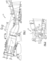
- Figure 1 depicts an idealized cross-sectional view of a turbine assembly 10, showing an example of an insertion path 11 of a maintenance apparatus 20.
- Figure 2 depicts an enlarged idealized cross-sectional view of a turbine assembly 10, showing an idealized depiction of the maintenance apparatus 20 disposed between adjacent blades of a rotor 12.
- the maintenance apparatus 20 may be inserted into the turbine assembly 10 with a suitably designed insertion device. Such insertion device would release the maintenance apparatus 20 once it is disposed between adjacent blades of a rotor 12.
- release means that the insertion device may mechanically decouple from the maintenance apparatus to allow the insertion device to avoid mechanical interference with moving turbine parts.
- a tether may or may not remain connecting the insertion device to the maintenance apparatus. If a tether is used, its size, shape and compliance are selected such that it does not create mechanical interference to rotating turbine parts.
- the maintenance apparatus 20 is positioned proximate to (i.e., near) a damaged region 40 located on the stator 13. This is achieved by rotating the rotor 12 and positioning the maintenance apparatus 20, which is disposed on the rotor 12, such that the repair tool 22 is located proximate to the damaged region 40 on the stator 13. Both the camera 21 and a repair tool 22 may be able to move on the apparatus 20, for example, along the dashed line 50. The repair tool 22 disposed on the maintenance apparatus 20 is then used to repair the damaged region 40.
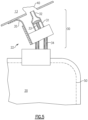
- repair tool 22 includes a ceramic patch application system 30, which includes a patch slurry reservoir 31, a patch slurry dispensing tip 32, a mechanical positioner 34 to move the dispensing tip 32 proximate a damaged region 40, a mechanical dispense actuator 33 to transport the patch slurry from the reservoir 31 to the damaged region 40 via the dispensing tip 32, and a mechanical wiper 35 to level the patch slurry over the damaged region 40.
- the invention is directed to a method for maintenance of a turbine assembly, the turbine assembly including a rotor and a stator, the rotor including a damaged region, the method including: disposing a remotely controllable maintenance apparatus on the stator; positioning the damaged region proximate to the maintenance apparatus by rotating the rotor; and repairing the damaged region by operating a repair tool disposed on the apparatus.
- a camera is disposed on the apparatus, wherein the camera is operable to remotely transmit visual data to a receiver. Such remote transmission may be done through a wired connection or wirelessly.
- a camera is disposed on the apparatus, wherein the camera is operable to wirelessly transmit visual data to a receiver.
- visual data is wirelessly transmitted from the camera to a receiver and, optionally, data regarding repair tool and camera position and configuration parameters may be wirelessly transmitted to a receiver.
- control data can be wirelessly transmitted to the camera or repair tool. Examples of control data include instructions to change camera position, repair tool position, and camera configuration parameters.
- the methods described herein further include anchoring the apparatus subsequent to disposing of the apparatus.
- anchoring can be achieved by means discussed above.
- operating the repair tool includes remotely transmitting a control signal to the apparatus. Such remote transmission may be done through a wired connection or wirelessly. Thus, in one embodiment, operating the repair tool includes wirelessly transmitting a control signal to the apparatus.
- the operating of the repair tool may also include removing material from the damaged region.
- operating the repair tool includes disposing a repair material on the damaged region.
- the operating of the repair tool may also include moving the repair tool on the apparatus.
- the damaged region may be a crack and repairing the damaged region would then include repairing the crack.
- the apparatus When the maintenance task is completed, the apparatus may be removed from the turbine assembly.
- the methods described herein may further include a step of removing the apparatus from the turbine assembly.
- Figure 3 depicts an idealized cross-sectional view of a turbine assembly 10, showing an example of an insertion path 14 of the maintenance apparatus 20.
- Figure 4 depicts an enlarged idealized cross-sectional view of the turbine assembly 10, showing an idealized depiction of the maintenance apparatus 20 disposed between adjacent guide vanes of a stator 13.
- the maintenance apparatus 20 may be inserted into the turbine assembly 10 with a suitably designed insertion device. Such insertion device would release the maintenance apparatus 20 once it is disposed between adjacent guide vanes of a stator 13.
- the maintenance apparatus 20 may be placed between any selected adjacent guide vanes.
- the maintenance apparatus 20 is positioned proximate to (i.e., near) a damaged region 40 located on the rotor 12.
- the repair tool 22 disposed on the maintenance apparatus 20 is then used to repair the damaged region 40.
- a camera 21 disposed on the maintenance apparatus 20 may be used to view the damaged region 40 and the repair process.
- the repair tool may be the same as the exemplary repair tool 22 shown in Figure 5 and discussed above. This repair tool 22 may be used to apply a patch slurry to a damaged region 40 on the rotor 12.
Landscapes
- Engineering & Computer Science (AREA)
- Mechanical Engineering (AREA)
- General Engineering & Computer Science (AREA)
- Structures Of Non-Positive Displacement Pumps (AREA)
- Manufacture Of Motors, Generators (AREA)
- Hydraulic Turbines (AREA)
- Turbine Rotor Nozzle Sealing (AREA)
Applications Claiming Priority (3)
| Application Number | Priority Date | Filing Date | Title |
|---|---|---|---|
| US15/198,754 US10920590B2 (en) | 2016-06-30 | 2016-06-30 | Turbine assembly maintenance methods |
| EP17733287.1A EP3478937B1 (de) | 2016-06-30 | 2017-06-15 | Wartungsverfahren für turbinenanordnung |
| PCT/US2017/037592 WO2018005107A1 (en) | 2016-06-30 | 2017-06-15 | Turbine assembly maintenance methods |
Related Parent Applications (2)
| Application Number | Title | Priority Date | Filing Date |
|---|---|---|---|
| EP17733287.1A Division EP3478937B1 (de) | 2016-06-30 | 2017-06-15 | Wartungsverfahren für turbinenanordnung |
| EP17733287.1A Division-Into EP3478937B1 (de) | 2016-06-30 | 2017-06-15 | Wartungsverfahren für turbinenanordnung |
Publications (3)
| Publication Number | Publication Date |
|---|---|
| EP4234894A2 true EP4234894A2 (de) | 2023-08-30 |
| EP4234894A3 EP4234894A3 (de) | 2023-10-11 |
| EP4234894B1 EP4234894B1 (de) | 2025-12-03 |
Family
ID=59216059
Family Applications (2)
| Application Number | Title | Priority Date | Filing Date |
|---|---|---|---|
| EP17733287.1A Active EP3478937B1 (de) | 2016-06-30 | 2017-06-15 | Wartungsverfahren für turbinenanordnung |
| EP23174180.2A Active EP4234894B1 (de) | 2016-06-30 | 2017-06-15 | Wartungsverfahren für turbinenanordnung |
Family Applications Before (1)
| Application Number | Title | Priority Date | Filing Date |
|---|---|---|---|
| EP17733287.1A Active EP3478937B1 (de) | 2016-06-30 | 2017-06-15 | Wartungsverfahren für turbinenanordnung |
Country Status (6)
| Country | Link |
|---|---|
| US (2) | US10920590B2 (de) |
| EP (2) | EP3478937B1 (de) |
| CN (1) | CN109312625B (de) |
| CA (1) | CA3028634A1 (de) |
| SG (1) | SG11201811141XA (de) |
| WO (1) | WO2018005107A1 (de) |
Families Citing this family (15)
| Publication number | Priority date | Publication date | Assignee | Title |
|---|---|---|---|---|
| US10738616B2 (en) | 2016-10-11 | 2020-08-11 | General Electric Company | System and method for maintenance of a turbine assembly |
| US10717166B2 (en) | 2016-12-02 | 2020-07-21 | General Electric Company | Motorized apparatus for use with rotary machines |
| US11608756B2 (en) * | 2018-07-17 | 2023-03-21 | General Electric Company | Service apparatus for use with rotary machines |
| US11010887B2 (en) * | 2018-09-17 | 2021-05-18 | General Electric Company | Automated distress ranking system |
| FR3087370B1 (fr) * | 2018-10-18 | 2020-12-11 | Safran Aircraft Engines | Procede et endoscope de reparation d'une piece de turbomachine |
| US11103964B2 (en) * | 2018-12-06 | 2021-08-31 | General Electric Company | Service apparatus for use with rotary machines |
| US11530621B2 (en) * | 2019-10-16 | 2022-12-20 | General Electric Company | Systems and method for use in servicing a machine |
| US12358845B2 (en) | 2020-04-15 | 2025-07-15 | General Electric Company | Consumable coatings and methods of protecting a high temperature component from dust deposits |
| EP3904668A1 (de) | 2020-04-28 | 2021-11-03 | GE Renewable Technologies | Verfahren und vorrichtung zur inspektion eines hydroturbinenlaufrads |
| US11913345B2 (en) | 2021-07-26 | 2024-02-27 | General Electric Company | System and method of using a tool assembly |
| US11524350B1 (en) * | 2021-10-04 | 2022-12-13 | General Electric Company | Backwall strike braze repair |
| US12031446B2 (en) | 2022-03-29 | 2024-07-09 | General Electric Company | Turbine engine servicing tool and method for using thereof |
| EP4283112A1 (de) * | 2022-05-23 | 2023-11-29 | GE Renewable Technologies | Verfahren und vorrichtung zum reparieren eines defektes oder einer beschädigung eines metallischen materialteils |
| US12359672B2 (en) | 2023-04-18 | 2025-07-15 | Rtx Corporation | Rotor blade inspection system |
| US12535015B2 (en) * | 2023-11-01 | 2026-01-27 | Rtx Corporation | Actively driven remote mount optical probe |
Citations (9)
| Publication number | Priority date | Publication date | Assignee | Title |
|---|---|---|---|---|
| US6413578B1 (en) | 2000-10-12 | 2002-07-02 | General Electric Company | Method for repairing a thermal barrier coating and repaired coating formed thereby |
| US6827969B1 (en) | 2003-12-12 | 2004-12-07 | General Electric Company | Field repairable high temperature smooth wear coating |
| US6875464B2 (en) | 2003-04-22 | 2005-04-05 | General Electric Company | In-situ method and composition for repairing a thermal barrier coating |
| US6890587B2 (en) | 2001-04-21 | 2005-05-10 | Alstom Technology Ltd | Method of repairing a ceramic coating |
| US7509735B2 (en) | 2004-04-22 | 2009-03-31 | Siemens Energy, Inc. | In-frame repairing system of gas turbine components |
| US8400501B2 (en) | 2008-05-12 | 2013-03-19 | Rolls-Royce Plc | Inspection arrangement |
| US8563080B2 (en) | 2007-03-24 | 2013-10-22 | Rolls-Royce Plc | Method of repairing a damaged abradable coating |
| US20150174837A1 (en) | 2013-12-19 | 2015-06-25 | General Electric Company | Turbine component patch delivery system |
| US20150175486A1 (en) | 2013-12-19 | 2015-06-25 | General Electric Company | Environmentally resistant patches and delivery systems |
Family Cites Families (73)
| Publication number | Priority date | Publication date | Assignee | Title |
|---|---|---|---|---|
| US4298312A (en) * | 1979-07-24 | 1981-11-03 | Purex Corporation | Damaged vane locating method and apparatus |
| US4639991A (en) * | 1981-11-16 | 1987-02-03 | United Technologies Corporation | Process for producing a new edge on an airfoil blade particularly the fan blade for a gas turbine engine |
| JPH065155B2 (ja) | 1984-10-12 | 1994-01-19 | 住友金属工業株式会社 | 窯炉の炉壁補修装置 |
| US5155941A (en) * | 1989-09-18 | 1992-10-20 | Olympus Optical Co., Ltd. | Industrial endoscope system having a rotary treatment member |
| US5197191A (en) * | 1991-03-04 | 1993-03-30 | General Electric Company | Repair of airfoil edges |
| US5349850A (en) * | 1992-11-19 | 1994-09-27 | General Electric Company | Instrumentation light probe holder |
| US5644394A (en) | 1994-10-19 | 1997-07-01 | United Technologies Corporation | System for repairing damaged gas turbine engine airfoils |
| US5723078A (en) | 1996-05-24 | 1998-03-03 | General Electric Company | Method for repairing a thermal barrier coating |
| US5759932A (en) | 1996-11-08 | 1998-06-02 | General Electric Company | Coating composition for metal-based substrates, and related processes |
| US5902647A (en) | 1996-12-03 | 1999-05-11 | General Electric Company | Method for protecting passage holes in a metal-based substrate from becoming obstructed, and related compositions |
| US6074706A (en) | 1998-12-15 | 2000-06-13 | General Electric Company | Adhesion of a ceramic layer deposited on an article by casting features in the article surface |
| US6042880A (en) | 1998-12-22 | 2000-03-28 | General Electric Company | Renewing a thermal barrier coating system |
| WO2001032228A1 (en) | 1999-11-02 | 2001-05-10 | Matsushita Electric Works, Ltd. | Hard tissue repairing material |
| US6235352B1 (en) | 1999-11-29 | 2001-05-22 | Electric Power Research Institute, Inc. | Method of repairing a thermal barrier coating |
| US6512199B1 (en) * | 1999-12-20 | 2003-01-28 | Anthony M. Blazina | Constant-speed motor-driven modular welding apparatus with electronic power control apparatus, electrode holder operation controls, and safety interlock |
| US6378159B1 (en) | 1999-12-27 | 2002-04-30 | Remco Products Corporation | Squeegee with liquid drain |
| US6497758B1 (en) | 2000-07-12 | 2002-12-24 | General Electric Company | Method for applying a high-temperature bond coat on a metal substrate, and related compositions and articles |
| GB0020461D0 (en) * | 2000-08-18 | 2000-10-11 | Oliver Crispin Consulting Ltd | Improvements in and relating to the robotic positioning of a work tool to a sensor |
| US6605160B2 (en) | 2000-08-21 | 2003-08-12 | Robert Frank Hoskin | Repair of coatings and surfaces using reactive metals coating processes |
| FR2827311B1 (fr) | 2001-07-12 | 2003-09-19 | Snecma Moteurs | Procede de reparation locale de pieces revetues d'une barriere thermique |
| US20030101587A1 (en) | 2001-10-22 | 2003-06-05 | Rigney Joseph David | Method for replacing a damaged TBC ceramic layer |
| US7032279B2 (en) * | 2002-10-18 | 2006-04-25 | General Electric Company | Apparatus and methods for repairing compressor airfoils in situ |
| US6881439B2 (en) | 2002-12-04 | 2005-04-19 | General Electric Company | Aluminide coating process |
| US6899593B1 (en) * | 2003-11-18 | 2005-05-31 | Dieter Moeller | Grinding apparatus for blending defects on turbine blades and associated method of use |
| US7093993B2 (en) | 2003-11-21 | 2006-08-22 | General Electric Company | Apparatus and methods for cleaning and priming of coated surfaces |
| US20050129868A1 (en) | 2003-12-11 | 2005-06-16 | Siemens Westinghouse Power Corporation | Repair of zirconia-based thermal barrier coatings |
| US7174788B2 (en) * | 2003-12-15 | 2007-02-13 | General Electric Company | Methods and apparatus for rotary machinery inspection |
| US6992315B2 (en) * | 2004-03-10 | 2006-01-31 | Siemens Westinghouse Power Corporation | In situ combustion turbine engine airfoil inspection |
| US7842335B2 (en) | 2004-04-07 | 2010-11-30 | General Electric Company | Field repairable high temperature smooth wear coating |
| US7588797B2 (en) | 2004-04-07 | 2009-09-15 | General Electric Company | Field repairable high temperature smooth wear coating |
| US20070087129A1 (en) * | 2005-10-19 | 2007-04-19 | Blankenship Donn R | Methods for repairing a workpiece |
| US7735222B2 (en) * | 2004-12-02 | 2010-06-15 | General Electric Company | Apparatus to remove material from a turbine wheel in-situ |
| US7231817B2 (en) * | 2005-01-18 | 2007-06-19 | Siemens Power Generation, Inc. | Inspection system for a turbine blade region of a turbine engine |
| FR2881146B1 (fr) * | 2005-01-27 | 2007-10-19 | Snecma Moteurs Sa | Procede de reparation d'une surface de frottement d'une aube a calage variable de turbomachine |
| EP1772228A1 (de) | 2005-10-07 | 2007-04-11 | Siemens Aktiengesellschaft | Verfahren zum Reparieren eines Bauteils mit einer gerichteten Mikrostruktur |
| US20070202269A1 (en) | 2006-02-24 | 2007-08-30 | Potter Kenneth B | Local repair process of thermal barrier coatings in turbine engine components |
| US20090074576A1 (en) | 2006-04-20 | 2009-03-19 | Florida Turbine Technologies, Inc. | Turbine blade with cooling breakout passages |
| US20100237134A1 (en) | 2006-07-17 | 2010-09-23 | David Vincent Bucci | Repair process for coated articles |
| DE102007029728A1 (de) | 2007-06-27 | 2009-01-08 | Rolls-Royce Deutschland Ltd & Co Kg | Verfahren und Vorrichtung zur Reparatur von Blisks von Gasturbinen |
| US8597724B2 (en) | 2007-07-06 | 2013-12-03 | United Technologies Corporation | Corrosion protective coating through cold spray |
| DE202007013205U1 (de) * | 2007-07-26 | 2008-12-11 | Erco Leuchten Gmbh | Leuchte |
| GB0722319D0 (en) * | 2007-11-14 | 2007-12-27 | Rolls Royce Plc | Component monitoring arrangement |
| US8887390B2 (en) * | 2008-08-15 | 2014-11-18 | Dresser-Rand Company | Method for correcting downstream deflection in gas turbine nozzles |
| US8157620B2 (en) * | 2008-12-23 | 2012-04-17 | General Electric Company | System and method for cleaning stator slots |
| US8221825B2 (en) | 2009-03-30 | 2012-07-17 | Alstom Technology Ltd. | Comprehensive method for local application and local repair of thermal barrier coatings |
| US9085053B2 (en) | 2009-12-22 | 2015-07-21 | United Technologies Corporation | In-situ turbine blade tip repair |
| SG173932A1 (en) | 2010-02-25 | 2011-09-29 | United Technologies Corp | Repair of a coating on a turbine component |
| CH704448A1 (de) | 2011-02-03 | 2012-08-15 | Alstom Technology Ltd | Verfahren zum Reparieren bzw. Rekonditionieren eines stark beschädigten Bauteils, insbesondere aus dem Heissgasbereich einer Gasturbine. |
| US8813331B2 (en) * | 2011-03-29 | 2014-08-26 | General Electric Company | Process of preparing a turbine rotor wheel, a repair wheel for a turbine rotor wheel, and a turbine rotor wheel |
| GB2504612B (en) * | 2011-05-09 | 2014-09-24 | Rolls Royce Plc | An apparatus for supporting a tool in an assembled apparatus |
| US8713775B2 (en) * | 2011-06-16 | 2014-05-06 | General Electric Company | Apparatus and method for servicing dynamoelectric machine components in-situ |
| US8365584B1 (en) * | 2011-07-13 | 2013-02-05 | General Electric Company | Apparatus for inspecting turbomachine components in-situ |
| US8826784B2 (en) * | 2011-08-29 | 2014-09-09 | United Technologies Corporation | Airfoil machining method and cutting tools |
| DE102011122759A1 (de) | 2011-11-02 | 2013-05-02 | Rolls-Royce Deutschland Ltd & Co Kg | Verfahren zur Inspektion einer Gasturbine |
| DE102011089701A1 (de) * | 2011-12-22 | 2013-06-27 | Lufthansa Technik Ag | Vorrichtung zum Rekonturieren einer Gasturbinenschaufel |
| DE102011089699B4 (de) * | 2011-12-22 | 2013-09-12 | Lufthansa Technik Ag | Vorrichtung zum Rekonturieren einer Gasturbinenschaufel |
| US9509923B2 (en) * | 2012-01-10 | 2016-11-29 | General Electric Company | Continuous infrared thermography monitoring and life management system for heat recovery steam generators |
| US8726502B2 (en) * | 2012-02-08 | 2014-05-20 | General Electric Company | Turbine servicing apparatus and methods |
| US20130232792A1 (en) * | 2012-03-12 | 2013-09-12 | General Electric Company | Apparatus and method for servicing turbomachinery components in-situ |
| US9267378B2 (en) | 2012-06-27 | 2016-02-23 | General Electric Company | Turbomachine monitoring system and method |
| CA2906400C (en) | 2013-03-15 | 2019-03-26 | Rolls-Royce Corporation | Repair of gas turbine engine components |
| US9895716B2 (en) | 2013-04-17 | 2018-02-20 | General Electric Company | Repair process and a repaired component |
| US20140352483A1 (en) | 2013-06-04 | 2014-12-04 | General Electric Company | Remote alignment tool |
| US9163322B2 (en) * | 2013-07-01 | 2015-10-20 | General Electric Company | Method and apparatus for refurbishing turbine components |
| US9513117B2 (en) | 2013-10-02 | 2016-12-06 | Siemens Energy, Inc. | Situ blade mounted tip gap measurement for turbines |
| PT2865487T (pt) * | 2013-10-24 | 2016-11-02 | Siemens Ag | Método e dispositivo para encurtar as lâminas móveis de uma turbomáquina |
| WO2015073196A1 (en) | 2013-11-18 | 2015-05-21 | United Technologies Corporation | Thermal barrier coating repair |
| FR3013996B1 (fr) | 2013-12-02 | 2017-04-28 | Office National Detudes Et De Rech Aerospatiales Onera | Procede de reparation locale de barrieres thermiques |
| US10022921B2 (en) | 2013-12-19 | 2018-07-17 | General Electric Company | Turbine component patch delivery systems and methods |
| US9540497B2 (en) | 2015-01-05 | 2017-01-10 | General Electric Company | Silicon-based repair methods and composition |
| US10713773B2 (en) * | 2015-09-08 | 2020-07-14 | General Electric Company | System and method for identifying a condition of rotary machine components |
| US10190442B2 (en) * | 2016-03-22 | 2019-01-29 | General Electric Company | Gas turbine in situ inflatable bladders for on-wing repair |
| US10738616B2 (en) | 2016-10-11 | 2020-08-11 | General Electric Company | System and method for maintenance of a turbine assembly |
-
2016
- 2016-06-30 US US15/198,754 patent/US10920590B2/en active Active
-
2017
- 2017-06-15 EP EP17733287.1A patent/EP3478937B1/de active Active
- 2017-06-15 EP EP23174180.2A patent/EP4234894B1/de active Active
- 2017-06-15 CA CA3028634A patent/CA3028634A1/en not_active Abandoned
- 2017-06-15 SG SG11201811141XA patent/SG11201811141XA/en unknown
- 2017-06-15 WO PCT/US2017/037592 patent/WO2018005107A1/en not_active Ceased
- 2017-06-15 CN CN201780040826.2A patent/CN109312625B/zh active Active
-
2021
- 2021-01-05 US US17/141,697 patent/US11339660B2/en active Active
Patent Citations (10)
| Publication number | Priority date | Publication date | Assignee | Title |
|---|---|---|---|---|
| US6413578B1 (en) | 2000-10-12 | 2002-07-02 | General Electric Company | Method for repairing a thermal barrier coating and repaired coating formed thereby |
| US6890587B2 (en) | 2001-04-21 | 2005-05-10 | Alstom Technology Ltd | Method of repairing a ceramic coating |
| US6875464B2 (en) | 2003-04-22 | 2005-04-05 | General Electric Company | In-situ method and composition for repairing a thermal barrier coating |
| US7476703B2 (en) | 2003-04-22 | 2009-01-13 | General Electric Company | In-situ method and composition for repairing a thermal barrier coating |
| US6827969B1 (en) | 2003-12-12 | 2004-12-07 | General Electric Company | Field repairable high temperature smooth wear coating |
| US7509735B2 (en) | 2004-04-22 | 2009-03-31 | Siemens Energy, Inc. | In-frame repairing system of gas turbine components |
| US8563080B2 (en) | 2007-03-24 | 2013-10-22 | Rolls-Royce Plc | Method of repairing a damaged abradable coating |
| US8400501B2 (en) | 2008-05-12 | 2013-03-19 | Rolls-Royce Plc | Inspection arrangement |
| US20150174837A1 (en) | 2013-12-19 | 2015-06-25 | General Electric Company | Turbine component patch delivery system |
| US20150175486A1 (en) | 2013-12-19 | 2015-06-25 | General Electric Company | Environmentally resistant patches and delivery systems |
Also Published As
| Publication number | Publication date |
|---|---|
| US10920590B2 (en) | 2021-02-16 |
| CN109312625B (zh) | 2022-06-07 |
| CA3028634A1 (en) | 2018-01-04 |
| WO2018005107A1 (en) | 2018-01-04 |
| US20210156254A1 (en) | 2021-05-27 |
| US11339660B2 (en) | 2022-05-24 |
| SG11201811141XA (en) | 2019-01-30 |
| EP3478937A1 (de) | 2019-05-08 |
| EP4234894B1 (de) | 2025-12-03 |
| CN109312625A (zh) | 2019-02-05 |
| EP4234894A3 (de) | 2023-10-11 |
| US20180003060A1 (en) | 2018-01-04 |
| EP3478937B1 (de) | 2023-11-29 |
Similar Documents
| Publication | Publication Date | Title |
|---|---|---|
| US11339660B2 (en) | Turbine assembly maintenance methods | |
| US11260477B2 (en) | Repair tool for turbomachinery and related method | |
| CN110073079B (zh) | 用于维护涡轮组件的维护设备和方法 | |
| US12420953B2 (en) | Inspection and repair tool | |
| EP3663515B1 (de) | Wartungsvorrichtung zur verwendung in turbinenanordnungen | |
| EP3208432B1 (de) | System und verfahren zur reparatur eines abreibbaren materials | |
| EP1944120A2 (de) | Schweißreparatur metallischer Komponenten | |
| CN101827683A (zh) | 固定的转子密封的修复 | |
| CN104583539A (zh) | 用于维修涡轮机械部件的装置和方法 | |
| EP3631170B1 (de) | Wartungsvorrichtung zur verwendung in drehmaschinen | |
| US10494926B2 (en) | System and method for maintaining machines | |
| CN110359970A (zh) | 用于检查、清洁和/或修理叶片的系统和方法 | |
| EP2946870A1 (de) | Boroskop und verfahren zur bearbeitung einer komponente in einer zusammengesetzten vorrichtung mithilfe eines boroskops | |
| US11608756B2 (en) | Service apparatus for use with rotary machines |
Legal Events
| Date | Code | Title | Description |
|---|---|---|---|
| PUAI | Public reference made under article 153(3) epc to a published international application that has entered the european phase |
Free format text: ORIGINAL CODE: 0009012 |
|
| STAA | Information on the status of an ep patent application or granted ep patent |
Free format text: STATUS: THE APPLICATION HAS BEEN PUBLISHED |
|
| AC | Divisional application: reference to earlier application |
Ref document number: 3478937 Country of ref document: EP Kind code of ref document: P |
|
| AK | Designated contracting states |
Kind code of ref document: A2 Designated state(s): AL AT BE BG CH CY CZ DE DK EE ES FI FR GB GR HR HU IE IS IT LI LT LU LV MC MK MT NL NO PL PT RO RS SE SI SK SM TR |
|
| REG | Reference to a national code |
Free format text: PREVIOUS MAIN CLASS: F01D0025280000 Ipc: F01D0005000000 Ref country code: DE Ref legal event code: R079 Ref document number: 602017093048 Country of ref document: DE |
|
| PUAL | Search report despatched |
Free format text: ORIGINAL CODE: 0009013 |
|
| AK | Designated contracting states |
Kind code of ref document: A3 Designated state(s): AL AT BE BG CH CY CZ DE DK EE ES FI FR GB GR HR HU IE IS IT LI LT LU LV MC MK MT NL NO PL PT RO RS SE SI SK SM TR |
|
| RIC1 | Information provided on ipc code assigned before grant |
Ipc: G02B 23/24 20060101ALI20230901BHEP Ipc: F01D 25/28 20060101ALI20230901BHEP Ipc: B23P 6/00 20060101ALI20230901BHEP Ipc: F01D 5/00 20060101AFI20230901BHEP |
|
| STAA | Information on the status of an ep patent application or granted ep patent |
Free format text: STATUS: REQUEST FOR EXAMINATION WAS MADE |
|
| 17P | Request for examination filed |
Effective date: 20240404 |
|
| RBV | Designated contracting states (corrected) |
Designated state(s): AL AT BE BG CH CY CZ DE DK EE ES FI FR GB GR HR HU IE IS IT LI LT LU LV MC MK MT NL NO PL PT RO RS SE SI SK SM TR |
|
| GRAP | Despatch of communication of intention to grant a patent |
Free format text: ORIGINAL CODE: EPIDOSNIGR1 |
|
| STAA | Information on the status of an ep patent application or granted ep patent |
Free format text: STATUS: GRANT OF PATENT IS INTENDED |
|
| INTG | Intention to grant announced |
Effective date: 20250731 |
|
| GRAS | Grant fee paid |
Free format text: ORIGINAL CODE: EPIDOSNIGR3 |
|
| GRAA | (expected) grant |
Free format text: ORIGINAL CODE: 0009210 |
|
| STAA | Information on the status of an ep patent application or granted ep patent |
Free format text: STATUS: THE PATENT HAS BEEN GRANTED |
|
| RAP3 | Party data changed (applicant data changed or rights of an application transferred) |
Owner name: GENERAL ELECTRIC COMPANY |
|
| AC | Divisional application: reference to earlier application |
Ref document number: 3478937 Country of ref document: EP Kind code of ref document: P |
|
| AK | Designated contracting states |
Kind code of ref document: B1 Designated state(s): AL AT BE BG CH CY CZ DE DK EE ES FI FR GB GR HR HU IE IS IT LI LT LU LV MC MK MT NL NO PL PT RO RS SE SI SK SM TR |
|
| P01 | Opt-out of the competence of the unified patent court (upc) registered |
Free format text: CASE NUMBER: UPC_APP_0011085_4234894/2025 Effective date: 20251027 |
|
| REG | Reference to a national code |
Ref country code: CH Ref legal event code: F10 Free format text: ST27 STATUS EVENT CODE: U-0-0-F10-F00 (AS PROVIDED BY THE NATIONAL OFFICE) Effective date: 20251203 Ref country code: GB Ref legal event code: FG4D |
|
| REG | Reference to a national code |
Ref country code: DE Ref legal event code: R096 Ref document number: 602017093048 Country of ref document: DE |
|
| REG | Reference to a national code |
Ref country code: IE Ref legal event code: FG4D |