EP4234859B1 - Vehicle door handle assembly - Google Patents
Vehicle door handle assembly Download PDFInfo
- Publication number
- EP4234859B1 EP4234859B1 EP22191999.6A EP22191999A EP4234859B1 EP 4234859 B1 EP4234859 B1 EP 4234859B1 EP 22191999 A EP22191999 A EP 22191999A EP 4234859 B1 EP4234859 B1 EP 4234859B1
- Authority
- EP
- European Patent Office
- Prior art keywords
- lever
- extremity
- vehicle door
- handle
- bracket
- Prior art date
- Legal status (The legal status is an assumption and is not a legal conclusion. Google has not performed a legal analysis and makes no representation as to the accuracy of the status listed.)
- Active
Links
Images



Classifications
-
- E—FIXED CONSTRUCTIONS
- E05—LOCKS; KEYS; WINDOW OR DOOR FITTINGS; SAFES
- E05B—LOCKS; ACCESSORIES THEREFOR; HANDCUFFS
- E05B85/00—Details of vehicle locks not provided for in groups E05B77/00 - E05B83/00
- E05B85/10—Handles
- E05B85/107—Pop-out handles, e.g. sliding outwardly before rotation
-
- E—FIXED CONSTRUCTIONS
- E05—LOCKS; KEYS; WINDOW OR DOOR FITTINGS; SAFES
- E05B—LOCKS; ACCESSORIES THEREFOR; HANDCUFFS
- E05B77/00—Vehicle locks characterised by special functions or purposes
- E05B77/42—Means for damping the movement of lock parts, e.g. slowing down the return movement of a handle
-
- E—FIXED CONSTRUCTIONS
- E05—LOCKS; KEYS; WINDOW OR DOOR FITTINGS; SAFES
- E05B—LOCKS; ACCESSORIES THEREFOR; HANDCUFFS
- E05B85/00—Details of vehicle locks not provided for in groups E05B77/00 - E05B83/00
- E05B85/10—Handles
- E05B85/103—Handles creating a completely closed wing surface
-
- E—FIXED CONSTRUCTIONS
- E05—LOCKS; KEYS; WINDOW OR DOOR FITTINGS; SAFES
- E05B—LOCKS; ACCESSORIES THEREFOR; HANDCUFFS
- E05B85/00—Details of vehicle locks not provided for in groups E05B77/00 - E05B83/00
- E05B85/10—Handles
- E05B85/14—Handles pivoted about an axis parallel to the wing
- E05B85/16—Handles pivoted about an axis parallel to the wing a longitudinal grip part being pivoted at one end about an axis perpendicular to the longitudinal axis of the grip part
Definitions
- the present invention relates to a vehicle door assembly, in particular of the type with a handle translating from a rest position where the handle is retracted and a deployed position where the handle is deployed and can be taken in hand and opened.
- Document KR 102 104 888 B1 discloses such a vehicle door assembly with a translating handle moved by a motor.
- One aim of the present invention is to find an economic and mechanical alternative for vehicle door handle assemblies having a translative movement.
- the invention as defined by claim 1 relates to a vehicle door handle assembly comprising a bracket and a handle, said handle comprising a first extremity and a second extremity opposed to the first extremity, the first extremity being connected to a first lever, said first lever being designed to be connected to an opening lever to open a latch of the vehicle door, said first lever being designed to rotate between a rest position where the first extremity of the handle is in a rest position, a deployed position where the first extremity of the handle is in a deployed position outside the bracket and an opening position where the first lever actuates the opening lever,
- the second extremity being connected to a second lever, said second lever being designed to rotate between a rest position where the second extremity of the handle is a rest position, an activation position where the second extremity of the handle lowers the second lever into the bracket, and a deployed position where the second extremity of the handle is in a deployed position outside the bracket,
- the vehicle door handle assembly also comprising a return lever having a first extremity connected to the second lever, said return lever being designed to rotate between a first position and a second position, the return lever comprising an elastic mean passively bringing back said return lever to its first position, the rotation of the second lever to its activation position actuates the rotation of the return lever from its first to its second position, and the passive rotation of the return lever from its second to its first position actuates the rotation of the second lever from its deployed position to its rest position.
- the return lever may be connected to a delay element which slows down the passive rotation of the return lever from its second to its first position.
- the delay element may comprise at least one damper.
- the at least one damper may comprise a gearwheel and a second extremity of the return lever connected to the at least one damper may comprise an arc portion with teeth engaged with said gearwheel.
- the second extremity of the return lever connected to the at least one damper may comprise a portion without teeth in order to disconnect the return lever of the at least one damper before the said return lever reaches its first position.
- the first lever may comprise an elastic mean passively bringing back said first lever from its deployed position to its rest position.
- the second lever may comprise an elastic mean passively rotating said second lever toward its deployed position.
- connection between the first lever and the first extremity of the handle may be a pivot-slide connection.
- the first and second levers may be connected together with at least one first rod, said first rod transmitting the rotation of the second lever from its activation position to its deployed position to the first lever, rotating said first lever from its rest position to its deployed position.
- the first rod may comprise a pivot-slide connection with anyone of the first or second lever so that the first lever can rotate from its rest position to its deployed position or from its deployed position to its opening position without rotating the second lever.
- the second and the return levers are connected together by a second and a third rods, said second rod transmitting the rotation of the second lever from its rest position to its activation position to the return lever, rotating said return lever from its first position to its second position, said third rod transmitting the rotation of the return lever from its second position to its first position to the second lever, rotating said second lever from its deployed position to its rest position.
- the second rod may comprise a pivot-slide connection with anyone of the second or return lever.
- the third rod comprises a pivot-slide connection with anyone of the second or return lever.
- the handle may be configured to be pushed into the bracket for lowering the second lever in activation position.
- the handle may be configured to move in a rectilinear manner when pushing the handle into the bracket.
- the handle is considered as a whole to be pushed by the user into the bracket. There is no rotation of the handle when a user is pushing on the handle.
- the handle may be configured to abut on a rest portion of the bracket in the activation position, the handle being distant from said rest portion when the first lever and second lever are both in rest position.
- the handle may present an external side facing the outside of the bracket; any part of the external side being configured to be pushed towards the bracket for lowering the second lever in activation position.
- the handle may include a leg linking the first extremity and the second extremity.
- the leg, the first extremity and the second extremity are each presenting a corresponding portion of the external side.
- the external side may present a contour corresponding to a contour on an opening of the bracket that receives the handle. Preferably, both contours merge in rest position of the first lever and second lever.
- the second extremity of the handle may be configured to be pushed into the bracket for lowering the second lever in activation position.
- the user activates the handle by pushing the second extremity of the handle into the bracket.
- the handle may be configured to rotate taking support on a rest portion of the bracket, the first extremity of the handle (2) protrudes from the bracket and rotates the first lever around its pivot connection with the bracket from its rest position to an intermediate position.
- the rest portion is placed between the first and second extremities of the handle.
- the rotation of the first lever is not transmitted to the second lever by the first rod due to the pivot-slide connection of the first rod with anyone of the first or second lever.
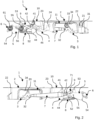
- FIGS 1 and 2 show a vehicle door handle assembly 1 in a rest position.
- the vehicle door handle assembly 1 comprises a bracket 10 and a handle 2.
- the bracket 10 is designed to be fixed on the vehicle door (not represented). In this rest position, the handle 2 is retracted into the bracket 10 in order to be at the same level of the door body when installed.
- the handle 2 comprises a first extremity 22 and a second extremity 23 opposed to the first extremity 22.
- the first extremity 22 of the handle 2 is connected to a first lever 3 and the second extremity 23 of the handle 2 is connected to a second lever 4.
- the first lever 3 is also designed to be connected to an opening lever (not represented) to open a latch of the vehicle door.
- the first lever 3 is designed to rotate between a rest position (represented in figures 1 and 2 ) where the first extremity 22 of the handle 2 is in a rest position, a deployed position (represented in figures 3 to 6 ) where the first extremity 22 of the handle 2 is in a deployed position outside the bracket 10 and an opening position (represented on figures 7 and 8 ) where the first lever 3 actuates the opening lever.
- the first lever 3 comprises a pivot connection 33 with the bracket 10 around which the first lever 3 rotates between its different positions.
- a first extremity of the first lever 3 is connected to the first extremity 22 of the handle 2 and a second extremity of the first lever 3, is connected to the opening lever, in particular, thanks to a pivot connection 31 and the shape of the first lever 3, the first lever 3 can touch the opening lever during the movement.
- the connection between the first lever 3 and the first extremity 22 of the handle is preferably a pivot-slide connection.
- the first extremity 22 of the handle 2 comprises a slide opening 21 and the first lever 3 comprises a recess 31 for example to receive a pin (not represented).
- the first lever 3 may also comprises an elastic mean 34 passively bringing back said first lever 3 from its deployed position to its rest position.
- This elastic mean 34 may be a spring positioned for example on the pivot connection 33 between the first lever 3 and the bracket 10.
- the torque applied by this elastic mean 34 is represented by a grey arrow in figures 1 to 8 .
- the second extremity 23 of the handle 2 is connected to a second lever 4.
- the second lever 4 is designed to rotate between a rest position (represented in figures 1 and 2 ) where the second extremity 23 of the handle 2 is in a rest position, an activation position (represented in figures 3 and 4 and 10 according to an alternative) where the second extremity 23 of the handle 2 lowers the second lever 4 into the bracket 10, and a deployed position (represented in figures 5 to 8 ) where the second extremity 23 of the handle 2 is in a deployed position outside the bracket 10.
- the second lever 4 comprises a pivot connection 41 with the bracket 10 around which the second lever 4 rotates between its different positions.
- a first extremity of the second lever 4 is connected to the second extremity 23 of the handle 2.
- This connection is preferably a pivot connection 24.
- the second lever 4 may also comprises an elastic mean (not represented) passively rotating said second lever 4 to its deployed position.
- This elastic mean may be a spring positioned for example on the pivot connection 41 between the second lever 4 and the bracket 10.
- the torque applied by this elastic mean is represented by a grey arrow in figures 1 to 8 .
- the first 3 and second 4 levers may be connected together with at least one first rod 7 in order to synchronize the movements of the two levers 3, 4. More exactly, the first rod 7 transmits the rotation of the second lever 4 from its activation position to its deployed position to the first lever 3, rotating said first lever 3 from its rest position to its deployed position.
- the first rod 7 may comprises a pivot-slide connection with anyone of the first 3 or second lever 4 so that the first lever 3 can rotate from its rest position to its deployed position or from its deployed position to its opening position without rotating the second lever 4.
- the first rod 7 comprises a first extremity connected to a second extremity of the first lever 3 by a pivot connection 32.
- the first rod 7 comprises a second extremity connected to the second lever 4 by pivot-slide connection.
- the second extremity of the first rod 7 comprises a slide 71 and the second extremity of the second lever 4 comprises a pin 42 inserted into said slide 71.
- the handle 2, the first lever 3, the second 4 lever and the first rod 7 are designed and connected like a parallelogram and move together synchronously.
- the other connection of the first rod 7 with anyone of the first 3 or second lever 4 is preferably a pivot connection.
- the vehicle door handle assembly 1 also comprises a return lever 5 having a first extremity connected to a second extremity of the second lever 4, said return lever 5 being designed to rotate between a first position (represented in figures 1 and 2 ) and a second position (represented in figures 3 to 8 ). More precisely, the return lever 5 comprises a pivot connection 55 with the bracket 10 around which the return lever 5 rotates between its different positions.
- the return lever 5 also comprises an elastic mean 56 passively bringing back said return lever 5 to its first position.
- This elastic mean 56 may be a spring positioned for example on the pivot connection 55 between the return lever 5 and the bracket 10. The torque applied by this elastic mean 56 is represented by a grey arrow on figures 1 to 8 .
- the rotation of the second lever 4 to its activation position actuates the rotation of the return lever 5 from its first to its second position.
- the passive rotation of the return lever 5 from its second to its first position actuates the rotation of the second lever 4 from its deployed position to its rest position.
- the second 4 and the return 5 levers are connected together by a second 8 and a third 9 rods.
- the second rod 8 transmits the rotation of the second lever 4 from its rest position to its activation position to the return lever 5, rotating said return lever 5 from its first position to its second position.
- the third rod 9 transmits the rotation of the return lever 5 from its second position to its first position to the second lever 4, rotating said second lever 4 from its deployed position to its rest position.
- the second 8 and the third 9 rods are placed on the return lever 5 on either side of the pivot connection 55 of the return lever 5 with the bracket 10.
- the second 8 and the third 9 rods are placed on the first extremity of second lever 5 on the same side of the pivot connection 41 of the second lever 4 with the bracket 10.
- the second rod 8 may comprises a pivot-slide connection 52 with anyone of the second lever 4 or return lever 5.
- the pivot-slide connection 52 is placed between the return lever 5 and the second rod 8.
- the return lever 5 comprises the slide of said pivot-slide connection 52 and the second rod 8 comprises a pin inserted in the slide.
- the connection between the second rod 8 and the second lever 4 is a pivot connection 44.
- the other connection of the second rod 8 with any of the second lever 4 or return lever 5 is preferably a pivot connection.
- the third rod 9 may comprises a pivot-slide connection 45 with any of the second lever 4 or return lever 5.
- the pivot-slide connection 45 is placed between the second lever 4 and the third rod 9.
- the second lever 4 comprises the slide of said pivot-slide connection 45 and the third rod 9 comprises a pin inserted in the slide.
- the connection between the third rod 9 and the return lever 5 is a pivot connection 53.
- the other connection of the third rod 9 with any of the second lever 4 or return lever 5 is preferably a pivot connection.
- the return lever 5, more exactly its second extremity, is connected to a delay element 6 which slows down the passive rotation of the return lever 5 from its second to its first position.
- This delay element 6 may comprises at least one damper as illustrated in figures 1 to 8 .
- the at least one damper 6 may comprises a gearwheel 61 and the extremity of the return lever 5, connected to the at least one damper 6, comprises an arc portion with teeth 54 engaged with said gearwheel 61.
- the torque applied by this at least one damper 6 is represented by a grey arrow on figures 1 to 8 .
- the figures 1 to 8 represent different positions and cinematic steps of the deployment, opening and retraction of the handle 2.
- figures 1 and 2 are a representation of a rest position where the handle 2 is retracted into the bracket 10 in order to be at the same level of the door body when installed.
- the first lever 3 is in its rest position and maintained in this rest position by the elastic mean 34.
- the second lever 4 is in its rest position and the return lever 5 is in its first position.
- the return lever 5 is maintained in its first position by the elastic mean 56.
- the elastic mean 56 of the return lever 5 is stronger than the elastic mean of the second lever 4 in order that the return lever 5 in its first position maintained the second lever 4 in its rest position.
- the elastic mean 56 of the return lever 5 is also stronger than the delay element 6 in order to maintain the return lever 5 in its first position.
- the inside of the handle 2 may also rests on a rest portion 11 of the bracket 10 placed between the first 22 and second 23 extremities of the handle 2.
- Figures 3 and 4 represent an activation position of the handle 2 according to an activation by rotation alternative where the user activates the handle 2 by pushing the second extremity 23 of the handle 2 into the bracket 10. Due to this push, the handle 2 rotates taking support on the rest portion 11 of the bracket 10. The first extremity 22 of the handle 2 protrudes from the bracket 10 and rotates the first lever 3 around its pivot connection 33 with the bracket 10 from its rest position to an intermediate. The rotation of the first lever 3 is not transmitted to the second lever 4 by the first rod 7 due to the pivot-slide connection of the first rod 7 with anyone of the first 3 or second lever 4.
- the push of the second extremity 23 of the handle 2 rotates the second lever 4 around its pivot connection 41 with the bracket 10 from its rest position to its activation position.
- the rotation of the second lever 4 causes the rotation of the return lever 5 around its pivot connection 55 with the bracket 10 from its first to its second position.
- the transmission of the rotation of the second lever 4 to the return lever 5 is made by the second rod 8 which pushes one side of the return lever 5 causing its rotation.
- the rotation of the second lever 4 to its activation position makes the second rod 8 slid in its slide-pivot connection with anyone of the second 4 or return lever 5 bringing the second rod 8 to abutment pushing the return lever 5.
- the third rod 9 slides in its slide-pivot connection with anyone of the second lever 4 or return lever 5 without affecting the rotation of anyone of these levers 4, 5.
- the rotation of the second lever 4 is made against the torque of its elastic mean and the rotation of the return lever 5 is made against the torque of its elastic mean 56.
- Figure 10 presents an activation by translation alternative, wherein there is an activation clearance 12 within the bracket 10 so that the handle 2 can be moved in a rectilinear manner from its rest position to the activation position as depicted.
- the handle 2 is pushed into the bracket for lowering the second lever 4 in activation position.
- the handle 2 moves in a rectilinear manner when pushing the handle into the bracket 10.
- the handle is considered as a whole to be pushed by the user into the bracket.
- the handle 2 is configured to abut on the rest portion 11 of the bracket 10 in the activation position, the handle 2 being distant from said rest portion 11 when the first lever 3 and second lever 4 are both in rest position.
- the handle 2 presents an external side 26 facing the outside of the bracket 10; any part of the external side 26 being configured to be pushed towards the bracket 10 for lowering the second lever 4 in activation position.
- the handle includes a leg 25 linking the first extremity and the second extremity.
- the leg 25, the first extremity and the second extremity are each presenting a corresponding portion of the external side 26.
- the external side 26 may present a contour corresponding to a contour on an opening of the bracket that receives the handle.
- both contours merge in rest position of the first lever and second lever. In other words, in rest position, both contours are at a corresponding level transversally to an extension plan of the external side 26.
- Figures 5 and 6 represent a deployed position of the handle 2 where the first lever 3 is still in its deployed position and where the second lever 4 has rotated from its activation position to its deployed position, bringing the second extremity 23 of the handle 2 in its deployed position outside the bracket 10.
- the elastic mean of the second lever 4 allows the passive rotation of the second lever 4 to its deployed position.
- the rotation of the second lever 4 is not transmitted to the return lever 5 by any of the second 8 or third rod 9 which slide with their pivot-slide connections.
- the first lever 3 is maintained in its deployed position due to the first rod 7 which is in abutment with its pivot-slide connection.
- the return lever 5 is still on its second position due to the delay element 6.
- the third rod 9 is in abutment in order to stop the rotation of the second lever 4 in its deployed position against the torque of its elastic mean 34.
- Figures 7 and 8 represent an opening position of the handle where the user can grab the handle and pull it or has taken the handle and pulled it in order to open the vehicle door.
- the handle 2 rotates around the pivot connection 24 between the second extremity 23 of the handle 2 and the second lever 4.
- the first extremity 22 of the handle 2 is pulled in an opening position rotating the first lever 3 from its deployed position to its opening position.
- the rotation of the first lever 3 is not transmitted to the second lever 4 by the first rod 7 due to its pivot-slide connection.
- the first lever 3 rotates back to its deployed position due to its elastic mean 34.
- the delay element 6 slows down the passive return rotation of the return lever 5 from its second position to its first position.
- the return lever 5 rotates from its second to its first position, it also transmits its rotation to the second lever 4 in order to rotate the second lever 4 from its deployed position to its rest position.
- the third rod 9 is in abutment in order to pull back the second lever 4 in its rest position against the torque of the elastic mean of the second lever4.
- the rotation of the second 4 and the first 3 levers to their rest position are synchronous due to the first rod 7.
- the handle 2 translates from its deployed position ( figures 5 and 6 ) to its rest position ( figures 1 and 2 ). This translation is slowed down and progressive thanks to the delay element 6.
- the extremity of the return lever 5 connected to the at least one damper 6 may comprises a portion without teeth 54 in order to disconnect the return lever 5 of the at least one damper 6 before said return lever 5 reaches its first position.
- This embodiment allows accelerating the return of the return lever 5 at the end and so accelerating the translation of the handle 2 from its deployed position to its rest position when the handle 2 is near its rest position.
Landscapes
- Lock And Its Accessories (AREA)
Description
- The present invention relates to a vehicle door assembly, in particular of the type with a handle translating from a rest position where the handle is retracted and a deployed position where the handle is deployed and can be taken in hand and opened.
-
- Such vehicle door handle assemblies with a handle translating between a rest position and a deployed position is becoming more common and requested by manufacturers.
- In order to translate between these two positions, such vehicle door handle assemblies are motorized by an electric actuator. Such electric vehicle door handle assemblies are expensive and are not suitable for entry-level vehicles clue to their costs. Furthermore,
- these vehicle door handle assemblies may be blocked or unusable in case of electrical power supply failure.
- Document
KR 102 104 888 B1 - One aim of the present invention is to find an economic and mechanical alternative for vehicle door handle assemblies having a translative movement.
- To this end, the invention as defined by
claim 1 relates to a vehicle door handle assembly comprising a bracket and a handle, said handle comprising a first extremity and a second extremity opposed to the first extremity, the first extremity being connected to a first lever, said first lever being designed to be connected to an opening lever to open a latch of the vehicle door, said first lever being designed to rotate between a rest position where the first extremity of the handle is in a rest position, a deployed position where the first extremity of the handle is in a deployed position outside the bracket and an opening position where the first lever actuates the opening lever, - the second extremity being connected to a second lever, said second lever being designed to rotate between a rest position where the second extremity of the handle is a rest position, an activation position where the second extremity of the handle lowers the second lever into the bracket, and a deployed position where the second extremity of the handle is in a deployed position outside the bracket, the vehicle door handle assembly also comprising a return lever having a first extremity connected to the second lever, said return lever being designed to rotate between a first position and a second position, the return lever comprising an elastic mean passively bringing back said return lever to its first position, the rotation of the second lever to its activation position actuates the rotation of the return lever from its first to its second position, and the passive rotation of the return lever from its second to its first position actuates the rotation of the second lever from its deployed position to its rest position.
- The return lever may be connected to a delay element which slows down the passive rotation of the return lever from its second to its first position.
- The delay element may comprise at least one damper.
- The at least one damper may comprise a gearwheel and a second extremity of the return lever connected to the at least one damper may comprise an arc portion with teeth engaged with said gearwheel.
- The second extremity of the return lever connected to the at least one damper may comprise a portion without teeth in order to disconnect the return lever of the at least one damper before the said return lever reaches its first position.
- The first lever may comprise an elastic mean passively bringing back said first lever from its deployed position to its rest position.
- The second lever may comprise an elastic mean passively rotating said second lever toward its deployed position.
- The connection between the first lever and the first extremity of the handle may be a pivot-slide connection.
- The first and second levers may be connected together with at least one first rod, said first rod transmitting the rotation of the second lever from its activation position to its deployed position to the first lever, rotating said first lever from its rest position to its deployed position.
- The first rod may comprise a pivot-slide connection with anyone of the first or second lever so that the first lever can rotate from its rest position to its deployed position or from its deployed position to its opening position without rotating the second lever.
- The second and the return levers are connected together by a second and a third rods, said second rod transmitting the rotation of the second lever from its rest position to its activation position to the return lever, rotating said return lever from its first position to its second position, said third rod transmitting the rotation of the return lever from its second position to its first position to the second lever, rotating said second lever from its deployed position to its rest position.
- The second rod may comprise a pivot-slide connection with anyone of the second or return lever.
- The third rod comprises a pivot-slide connection with anyone of the second or return lever.
- The handle may be configured to be pushed into the bracket for lowering the second lever in activation position.
- The handle may be configured to move in a rectilinear manner when pushing the handle into the bracket.
- Here, the handle is considered as a whole to be pushed by the user into the bracket. There is no rotation of the handle when a user is pushing on the handle.
- The handle may be configured to abut on a rest portion of the bracket in the activation position, the handle being distant from said rest portion when the first lever and second lever are both in rest position.
- In other words, there is an activation clearance within the bracket so that the handle can be moved in a rectilinear manner from its rest position to the activation position.
- The handle may present an external side facing the outside of the bracket; any part of the external side being configured to be pushed towards the bracket for lowering the second lever in activation position.
- The handle may include a leg linking the first extremity and the second extremity. The leg, the first extremity and the second extremity are each presenting a corresponding portion of the external side.
- The external side may present a contour corresponding to a contour on an opening of the bracket that receives the handle. Preferably, both contours merge in rest position of the first lever and second lever.
- Alternatively, the second extremity of the handle may be configured to be pushed into the bracket for lowering the second lever in activation position. In this alternative, the user activates the handle by pushing the second extremity of the handle into the bracket.
- In this alternative, the handle may be configured to rotate taking support on a rest portion of the bracket, the first extremity of the handle (2) protrudes from the bracket and rotates the first lever around its pivot connection with the bracket from its rest position to an intermediate position.
- Here, there is no activation clearance and the handle as a whole cannot translate in a rectilinear manner within the bracket. Instead, there is a rotation of the handle taking support on the rest portion. Thus, in this alternative, the user should push on the second extremity to rotate handle for moving the second lever in activation position.
- The rest portion is placed between the first and second extremities of the handle.
- The rotation of the first lever is not transmitted to the second lever by the first rod due to the pivot-slide connection of the first rod with anyone of the first or second lever.
- In this alternative, when the first lever and the second lever are both in rest position, the inside of the handle rests on the rest portion of the bracket. Here, the geometry of the rest portion is similar but there is no activation clearance.
- Further features and advantages of the invention will become apparent from the following description, given by way of non-limiting example, with reference to the appended drawings, in which:
-
Figure 1 is a top view of a schematic representation of a first side of a vehicle door assembly in a rest position, -
Figure 2 is a bottom view of a schematic representation of a second side of a vehicle door assembly in a rest position, -
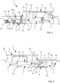
Figure 3 is a top view of a schematic representation of a first side of a vehicle door assembly in an activation position according to an activation by rotation alternative, -
Figure 4 is a bottom view of a schematic representation of a second side of a vehicle door assembly in an activation position according to the activation by rotation alternative, -
Figure 5 is a top view of a schematic representation of a first side of a vehicle door assembly in a deployed position, -
Figure 6 is a bottom view of a schematic representation of a second side of a vehicle door assembly in a deployed position, -
Figure 7 is a top view of a schematic representation of a first side of a vehicle door assembly in an opening position, -
Figure 8 is a bottom view of a schematic representation of a second side of a vehicle door assembly in an opening position, -
Figure 9 is a schematic representation of a second lever according to a particular embodiment, -
Figure 10 is a perspective view of the vehicle door assembly on the activation position according to an activation by translation alternative. - In these figures, identical elements bear the same reference numbers. The following implementations are examples. Although the description refers to one or more embodiments, this does not necessarily mean that each reference relates to the same embodiment or that the features apply only to a single embodiment.
-
Figures 1 and 2 show a vehicledoor handle assembly 1 in a rest position. The vehicledoor handle assembly 1 comprises abracket 10 and ahandle 2. Thebracket 10 is designed to be fixed on the vehicle door (not represented). In this rest position, thehandle 2 is retracted into thebracket 10 in order to be at the same level of the door body when installed. - The
handle 2 comprises afirst extremity 22 and asecond extremity 23 opposed to thefirst extremity 22. Thefirst extremity 22 of thehandle 2 is connected to afirst lever 3 and thesecond extremity 23 of thehandle 2 is connected to asecond lever 4. - The
first lever 3 is also designed to be connected to an opening lever (not represented) to open a latch of the vehicle door. Thefirst lever 3 is designed to rotate between a rest position (represented infigures 1 and 2 ) where thefirst extremity 22 of thehandle 2 is in a rest position, a deployed position (represented infigures 3 to 6 ) where thefirst extremity 22 of thehandle 2 is in a deployed position outside thebracket 10 and an opening position (represented onfigures 7 and 8 ) where thefirst lever 3 actuates the opening lever. - More precisely, the
first lever 3 comprises apivot connection 33 with thebracket 10 around which thefirst lever 3 rotates between its different positions. A first extremity of thefirst lever 3 is connected to thefirst extremity 22 of thehandle 2 and a second extremity of thefirst lever 3, is connected to the opening lever, in particular, thanks to apivot connection 31 and the shape of thefirst lever 3, thefirst lever 3 can touch the opening lever during the movement. - The connection between the
first lever 3 and thefirst extremity 22 of the handle is preferably a pivot-slide connection. In the examples representedfigures 1 ,3 ,5 , and7 , thefirst extremity 22 of thehandle 2 comprises aslide opening 21 and thefirst lever 3 comprises arecess 31 for example to receive a pin (not represented). Thefirst lever 3 may also comprises an elastic mean 34 passively bringing back saidfirst lever 3 from its deployed position to its rest position. This elastic mean 34 may be a spring positioned for example on thepivot connection 33 between thefirst lever 3 and thebracket 10. The torque applied by this elastic mean 34 is represented by a grey arrow infigures 1 to 8 . - The
second extremity 23 of thehandle 2 is connected to asecond lever 4. Thesecond lever 4 is designed to rotate between a rest position (represented infigures 1 and 2 ) where thesecond extremity 23 of thehandle 2 is in a rest position, an activation position (represented infigures 3 and 4 and10 according to an alternative) where thesecond extremity 23 of thehandle 2 lowers thesecond lever 4 into thebracket 10, and a deployed position (represented infigures 5 to 8 ) where thesecond extremity 23 of thehandle 2 is in a deployed position outside thebracket 10. - More precisely, the
second lever 4 comprises apivot connection 41 with thebracket 10 around which thesecond lever 4 rotates between its different positions. A first extremity of thesecond lever 4 is connected to thesecond extremity 23 of thehandle 2. This connection is preferably apivot connection 24. Thesecond lever 4 may also comprises an elastic mean (not represented) passively rotating saidsecond lever 4 to its deployed position. This elastic mean may be a spring positioned for example on thepivot connection 41 between thesecond lever 4 and thebracket 10. The torque applied by this elastic mean is represented by a grey arrow infigures 1 to 8 . - The first 3 and second 4 levers may be connected together with at least one
first rod 7 in order to synchronize the movements of the twolevers first rod 7 transmits the rotation of thesecond lever 4 from its activation position to its deployed position to thefirst lever 3, rotating saidfirst lever 3 from its rest position to its deployed position. Thefirst rod 7 may comprises a pivot-slide connection with anyone of the first 3 orsecond lever 4 so that thefirst lever 3 can rotate from its rest position to its deployed position or from its deployed position to its opening position without rotating thesecond lever 4. In the example illustrated infigures 1 to 8 , thefirst rod 7 comprises a first extremity connected to a second extremity of thefirst lever 3 by apivot connection 32. Thefirst rod 7 comprises a second extremity connected to thesecond lever 4 by pivot-slide connection. The second extremity of thefirst rod 7 comprises aslide 71 and the second extremity of thesecond lever 4 comprises apin 42 inserted into saidslide 71. Thehandle 2, thefirst lever 3, the second 4 lever and thefirst rod 7 are designed and connected like a parallelogram and move together synchronously. The other connection of thefirst rod 7 with anyone of the first 3 orsecond lever 4 is preferably a pivot connection. - The vehicle
door handle assembly 1 also comprises areturn lever 5 having a first extremity connected to a second extremity of thesecond lever 4, saidreturn lever 5 being designed to rotate between a first position (represented infigures 1 and 2 ) and a second position (represented infigures 3 to 8 ). More precisely, thereturn lever 5 comprises apivot connection 55 with thebracket 10 around which thereturn lever 5 rotates between its different positions. Thereturn lever 5 also comprises an elastic mean 56 passively bringing back saidreturn lever 5 to its first position. This elastic mean 56 may be a spring positioned for example on thepivot connection 55 between thereturn lever 5 and thebracket 10. The torque applied by this elastic mean 56 is represented by a grey arrow onfigures 1 to 8 . - The rotation of the
second lever 4 to its activation position actuates the rotation of thereturn lever 5 from its first to its second position. The passive rotation of thereturn lever 5 from its second to its first position actuates the rotation of thesecond lever 4 from its deployed position to its rest position. - The second 4 and the
return 5 levers are connected together by a second 8 and a third 9 rods. Thesecond rod 8 transmits the rotation of thesecond lever 4 from its rest position to its activation position to thereturn lever 5, rotating saidreturn lever 5 from its first position to its second position. Thethird rod 9 transmits the rotation of thereturn lever 5 from its second position to its first position to thesecond lever 4, rotating saidsecond lever 4 from its deployed position to its rest position. The second 8 and the third 9 rods are placed on thereturn lever 5 on either side of thepivot connection 55 of thereturn lever 5 with thebracket 10. The second 8 and the third 9 rods are placed on the first extremity ofsecond lever 5 on the same side of thepivot connection 41 of thesecond lever 4 with thebracket 10. - The
second rod 8 may comprises a pivot-slide connection 52 with anyone of thesecond lever 4 or returnlever 5. In the example illustrated infigures 1 to 8 , the pivot-slide connection 52 is placed between thereturn lever 5 and thesecond rod 8. Thereturn lever 5 comprises the slide of said pivot-slide connection 52 and thesecond rod 8 comprises a pin inserted in the slide. Still according to the example illustrated infigures 1 to 8 , the connection between thesecond rod 8 and thesecond lever 4 is apivot connection 44. The other connection of thesecond rod 8 with any of thesecond lever 4 or returnlever 5 is preferably a pivot connection. - The
third rod 9 may comprises a pivot-slide connection 45 with any of thesecond lever 4 or returnlever 5. In the example illustrated infigures 1 to 8 , the pivot-slide connection 45 is placed between thesecond lever 4 and thethird rod 9. Thesecond lever 4 comprises the slide of said pivot-slide connection 45 and thethird rod 9 comprises a pin inserted in the slide. Still according to the example illustrated infigures 1 to 8 , the connection between thethird rod 9 and thereturn lever 5 is apivot connection 53. The other connection of thethird rod 9 with any of thesecond lever 4 or returnlever 5 is preferably a pivot connection. - The
return lever 5, more exactly its second extremity, is connected to adelay element 6 which slows down the passive rotation of thereturn lever 5 from its second to its first position. Thisdelay element 6 may comprises at least one damper as illustrated infigures 1 to 8 . The at least onedamper 6 may comprises agearwheel 61 and the extremity of thereturn lever 5, connected to the at least onedamper 6, comprises an arc portion withteeth 54 engaged with saidgearwheel 61. The torque applied by this at least onedamper 6 is represented by a grey arrow onfigures 1 to 8 . - The
figures 1 to 8 represent different positions and cinematic steps of the deployment, opening and retraction of thehandle 2. - As described above,
figures 1 and 2 are a representation of a rest position where thehandle 2 is retracted into thebracket 10 in order to be at the same level of the door body when installed. Thefirst lever 3 is in its rest position and maintained in this rest position by theelastic mean 34. Thesecond lever 4 is in its rest position and thereturn lever 5 is in its first position. Thereturn lever 5 is maintained in its first position by theelastic mean 56. The elastic mean 56 of thereturn lever 5 is stronger than the elastic mean of thesecond lever 4 in order that thereturn lever 5 in its first position maintained thesecond lever 4 in its rest position. The elastic mean 56 of thereturn lever 5 is also stronger than thedelay element 6 in order to maintain thereturn lever 5 in its first position. In this rest position, the inside of thehandle 2 may also rests on arest portion 11 of thebracket 10 placed between the first 22 and second 23 extremities of thehandle 2. -
Figures 3 and 4 represent an activation position of thehandle 2 according to an activation by rotation alternative where the user activates thehandle 2 by pushing thesecond extremity 23 of thehandle 2 into thebracket 10. Due to this push, thehandle 2 rotates taking support on therest portion 11 of thebracket 10. Thefirst extremity 22 of thehandle 2 protrudes from thebracket 10 and rotates thefirst lever 3 around itspivot connection 33 with thebracket 10 from its rest position to an intermediate. The rotation of thefirst lever 3 is not transmitted to thesecond lever 4 by thefirst rod 7 due to the pivot-slide connection of thefirst rod 7 with anyone of the first 3 orsecond lever 4. - The push of the
second extremity 23 of thehandle 2 rotates thesecond lever 4 around itspivot connection 41 with thebracket 10 from its rest position to its activation position. The rotation of thesecond lever 4 causes the rotation of thereturn lever 5 around itspivot connection 55 with thebracket 10 from its first to its second position. In the example illustrated infigures 3 and 4 , the transmission of the rotation of thesecond lever 4 to thereturn lever 5 is made by thesecond rod 8 which pushes one side of thereturn lever 5 causing its rotation. Indeed, the rotation of thesecond lever 4 to its activation position makes thesecond rod 8 slid in its slide-pivot connection with anyone of the second 4 or returnlever 5 bringing thesecond rod 8 to abutment pushing thereturn lever 5. Thethird rod 9 slides in its slide-pivot connection with anyone of thesecond lever 4 or returnlever 5 without affecting the rotation of anyone of theselevers second lever 4 is made against the torque of its elastic mean and the rotation of thereturn lever 5 is made against the torque of itselastic mean 56. -
Figure 10 presents an activation by translation alternative, wherein there is anactivation clearance 12 within thebracket 10 so that thehandle 2 can be moved in a rectilinear manner from its rest position to the activation position as depicted. - The
handle 2 is pushed into the bracket for lowering thesecond lever 4 in activation position. - Due the presence of the
activation clearance 12, thehandle 2 moves in a rectilinear manner when pushing the handle into thebracket 10. Thus, the handle is considered as a whole to be pushed by the user into the bracket. There is no rotation of the handle when a user is pushing on the handle. - The
handle 2 is configured to abut on therest portion 11 of thebracket 10 in the activation position, thehandle 2 being distant from saidrest portion 11 when thefirst lever 3 andsecond lever 4 are both in rest position. - The
handle 2 presents anexternal side 26 facing the outside of thebracket 10; any part of theexternal side 26 being configured to be pushed towards thebracket 10 for lowering thesecond lever 4 in activation position. - The handle includes a
leg 25 linking the first extremity and the second extremity. Theleg 25, the first extremity and the second extremity are each presenting a corresponding portion of theexternal side 26. - The
external side 26 may present a contour corresponding to a contour on an opening of the bracket that receives the handle. Preferably, both contours merge in rest position of the first lever and second lever. In other words, in rest position, both contours are at a corresponding level transversally to an extension plan of theexternal side 26. - Both the alternatives with an activation by rotation and an activation by translation are compatible with the other constructional features herein described. Only the position of the
rest portion 11 differs. Therest portion 11 is deeper within thebracket 10 according to the activation by translation alternative. -
Figures 5 and 6 represent a deployed position of thehandle 2 where thefirst lever 3 is still in its deployed position and where thesecond lever 4 has rotated from its activation position to its deployed position, bringing thesecond extremity 23 of thehandle 2 in its deployed position outside thebracket 10. When the user removes his push on thesecond extremity 23 of thehandle 2, the elastic mean of thesecond lever 4 allows the passive rotation of thesecond lever 4 to its deployed position. The rotation of thesecond lever 4 is not transmitted to thereturn lever 5 by any of the second 8 orthird rod 9 which slide with their pivot-slide connections. Thefirst lever 3 is maintained in its deployed position due to thefirst rod 7 which is in abutment with its pivot-slide connection. Thereturn lever 5 is still on its second position due to thedelay element 6. - The
third rod 9 is in abutment in order to stop the rotation of thesecond lever 4 in its deployed position against the torque of itselastic mean 34. -
Figures 7 and 8 represent an opening position of the handle where the user can grab the handle and pull it or has taken the handle and pulled it in order to open the vehicle door. When the user pulls thehandle 2, it rotates around thepivot connection 24 between thesecond extremity 23 of thehandle 2 and thesecond lever 4. Thefirst extremity 22 of thehandle 2 is pulled in an opening position rotating thefirst lever 3 from its deployed position to its opening position. The rotation of thefirst lever 3 is not transmitted to thesecond lever 4 by thefirst rod 7 due to its pivot-slide connection. When the user releases thehandle 2, thefirst lever 3 rotates back to its deployed position due to itselastic mean 34. - The
delay element 6 slows down the passive return rotation of thereturn lever 5 from its second position to its first position. When thereturn lever 5 rotates from its second to its first position, it also transmits its rotation to thesecond lever 4 in order to rotate thesecond lever 4 from its deployed position to its rest position. In the example illustrated infigures 7 and 8 , when thereturn lever 5 rotates to its first position, thethird rod 9 is in abutment in order to pull back thesecond lever 4 in its rest position against the torque of the elastic mean of the second lever4. The rotation of the second 4 and the first 3 levers to their rest position are synchronous due to thefirst rod 7. Thus, thehandle 2 translates from its deployed position (figures 5 and 6 ) to its rest position (figures 1 and 2 ). This translation is slowed down and progressive thanks to thedelay element 6. - In a particular embodiment illustrated in
figure 9 , the extremity of thereturn lever 5 connected to the at least onedamper 6 may comprises a portion withoutteeth 54 in order to disconnect thereturn lever 5 of the at least onedamper 6 before saidreturn lever 5 reaches its first position. This embodiment allows accelerating the return of thereturn lever 5 at the end and so accelerating the translation of thehandle 2 from its deployed position to its rest position when thehandle 2 is near its rest position. -
- 10: bracket
- 11: rest bracket
- 12: activation clearance
- 2: handle
- 21: slide of the first extremity of the handle
- 22: first extremity of the handle
- 23: second extremity of the handle
- 24: second extremity pivot connection
- 25: leg of the handle
- 26: external side of the handle
- 3: first lever
- 31: recess at the first extremity of the first lever
- 32: pivot connection of the first lever with first rod
- 33: pivot connection of the first lever with bracket
- 34: elastic mean
- 4: second lever
- 41: pivot connection of the second lever with the bracket
- 42: pivot connection of the second lever with first rod
- 44: pivot connection of the of the second lever with the second rod
- 45: slide-pivot connection of the second lever with the third rod
- 5: return lever
- 52: slide-pivot connection of the return lever with the second rod
- 53: pivot connection of the return lever with the third rod
- 54: teeth of the return lever
- 55: pivot connection of the return lever with the bracket
- 56: elastic mean
- 6: damper
- 61: gear
- 62: fixing mean
- 7: first rod
- 71: extremity slide of the first rod
- 8: second rod
- 9: third rod
Claims (19)
- Vehicle door handle assembly (1) comprising a bracket (10) and a handle (2), said handle (2) comprising a first extremity (22) and a second extremity (23) opposed to the first extremity (22),the first extremity (22) being connected to a first lever (3), said first lever (3) being designed to be connected to an opening lever to open a latch of the vehicle door, said first lever (3) being designed to rotate between a rest position where the first extremity (22) of the handle (2) is in a rest position, a deployed position where the first extremity (22) of the handle (2) is in a deployed position outside the bracket (10) and an opening position where the first lever (3) actuates the opening lever,the second extremity (23) being connected to a second lever (4), said second lever (4) being designed to rotate between a rest position where the second extremity (23) of the handle (2) is a rest position, an activation position where the second extremity (23) of the handle (2) lowers the second lever (4) into the bracket (10), and a deployed position where the second extremity (23) of the handle (2) is in a deployed position outside the bracket (10),the vehicle door handle assembly (1) also comprising a return lever (5) having a first extremity connected to the second lever (4), said return lever (5) being designed to rotate between a first position and a second position, the return lever (5) comprising an elastic mean (56) passively bringing back said return lever (5) to its first position,the rotation of the second lever (4) to its activation position actuates the rotation of the return lever (5) from its first to its second position, and the passive rotation of the return lever (5) from its second to its first position actuates the rotation of the second lever (4) from its deployed position to its rest position,wherein the second (4) and the return (5) levers are connected together by a second (8) and a third (9) rods, said second rod (8) transmitting the rotation of the second lever (4) from its rest position to its activation position to the return lever (5), rotating said return lever (5) from its first position to its second position, said third rod (9) transmitting the rotation of the return lever (5) from its second position to its first position to the second lever (4), rotating said second lever (4) from its deployed position to its rest position.
- Vehicle door handle assembly (1) according to the previous claim, wherein the return lever (5) is connected to a delay element (6) which slows down the passive rotation of the return lever (5) from its second to its first position.
- Vehicle door handle assembly (1) according to the previous claim, wherein the delay element (6) comprises at least one damper.
- Vehicle door handle assembly (1) according to the previous claim, wherein the at least one damper (6) comprises a gearwheel (61) and wherein a second extremity of the return lever (5) connected to the at least one damper (6) comprises an arc portion with teeth (54) engaged with said gearwheel (61).
- Vehicle door handle assembly (1) according to the previous claim, wherein the second extremity of the return lever (5) connected to the at least one damper (6) comprises a portion without teeth (54) in order to disconnect the return lever (5) of the at least one damper (6) before the said return lever (5) reaches its first position.
- Vehicle door handle assembly (1) according to anyone of the previous claims, wherein the first lever (3) comprises an elastic mean (34) passively bringing back said first lever (3) from its deployed position to its rest position.
- Vehicle door handle assembly (1) according to anyone of the previous claims, wherein the second lever (4) comprises an elastic mean passively rotating said second lever (4) toward its deployed position.
- Vehicle door handle assembly (1) according to anyone of the previous claims, wherein the connection between the first lever (3) and the first extremity (22) of the handle is a pivot-slide connection.
- Vehicle door handle assembly (1) according to anyone of the previous claims, wherein the first (3) and second (4) levers are connected together with at least one first rod (7), said first rod (7) transmitting the rotation of the second lever (4) from its activation position to its deployed position to the first lever (3), rotating said first lever (3) from its rest position to its deployed position.
- Vehicle door handle assembly (1) according to the previous claim, wherein the first rod (7) comprises a pivot-slide connection with anyone of the first (3) or second lever (4) so that the first lever (3) can rotate from its rest position to its deployed position or from its deployed position to its opening position without rotating the second lever (4).
- Vehicle door handle assembly (1) according to one of claims 1 to 10, wherein the second rod (8) comprises a pivot-slide connection with anyone of the second (4) or return lever (5)
- Vehicle door handle assembly (1) according to one of claims 1 to 10, wherein the third rod (9) comprises a pivot-slide connection with anyone of the second (4) or return lever (5).
- Vehicle door handle assembly (1) according to one of the claims 1 to 12, wherein the handle (2) is configured to be pushed into the bracket (10) for lowering the second lever (4) in activation position.
- Vehicle door handle assembly (1) according to claim 13, wherein the handle (2) is configured to move in a rectilinear manner when pushing the handle into the bracket (10).
- Vehicle door handle assembly (1) according to claim 14, wherein the handle (2) is configured to abut on a rest portion (11) of the bracket (10) in the activation position, the handle (2) being distant from said rest portion (11) when the first lever (3) and second lever (4) are both in rest position.
- Vehicle door handle assembly (1) according to one of the claims 13 to 15, wherein the handle (2) presents an external side (26) facing the outside of the bracket (10); any part of the external side (26) being configured to be pushed towards the bracket (10) for lowering the second lever (4) in activation position.
- Vehicle door handle assembly (1) according to one of the claims 1 to 12, wherein the second extremity (23) of the handle (2) is configured to be pushed into the bracket (10) for lowering the second lever (4) in activation position.
- Vehicle door handle assembly (1) according to claim 17, wherein the handle (2) is configured to rotate taking support on a rest portion (11) of the bracket (10), the first extremity (22) of the handle (2) protrudes from the bracket (10) and rotates the first lever (3) around its pivot connection (33) with the bracket (10) from its rest position to an intermediate position.
- Vehicle door handle assembly (1) according to claim 18, wherein when the first lever (3) and the second lever (4) are both in rest position, the inside of the handle (2) rests on the rest portion (11) of the bracket (10).
Priority Applications (4)
| Application Number | Priority Date | Filing Date | Title |
|---|---|---|---|
| EP23152938.9A EP4234860B1 (en) | 2022-02-23 | 2023-01-23 | Vehicle door handle assembly |
| ES23152938T ES3022683T3 (en) | 2022-02-23 | 2023-01-23 | Vehicle door handle assembly |
| CN202310155971.2A CN116641607A (en) | 2022-02-23 | 2023-02-23 | door handle assembly |
| US18/113,145 US12286821B2 (en) | 2022-02-23 | 2023-02-23 | Vehicle door handle assembly |
Applications Claiming Priority (1)
| Application Number | Priority Date | Filing Date | Title |
|---|---|---|---|
| EP22158287.7A EP4234858B1 (en) | 2022-02-23 | 2022-02-23 | Vehicle door handle assembly |
Publications (2)
| Publication Number | Publication Date |
|---|---|
| EP4234859A1 EP4234859A1 (en) | 2023-08-30 |
| EP4234859B1 true EP4234859B1 (en) | 2025-03-19 |
Family
ID=80448623
Family Applications (2)
| Application Number | Title | Priority Date | Filing Date |
|---|---|---|---|
| EP22158287.7A Active EP4234858B1 (en) | 2022-02-23 | 2022-02-23 | Vehicle door handle assembly |
| EP22191999.6A Active EP4234859B1 (en) | 2022-02-23 | 2022-08-24 | Vehicle door handle assembly |
Family Applications Before (1)
| Application Number | Title | Priority Date | Filing Date |
|---|---|---|---|
| EP22158287.7A Active EP4234858B1 (en) | 2022-02-23 | 2022-02-23 | Vehicle door handle assembly |
Country Status (3)
| Country | Link |
|---|---|
| US (1) | US12385298B2 (en) |
| EP (2) | EP4234858B1 (en) |
| CN (1) | CN116641605A (en) |
Families Citing this family (1)
| Publication number | Priority date | Publication date | Assignee | Title |
|---|---|---|---|---|
| US20250215731A1 (en) * | 2023-12-28 | 2025-07-03 | Sl Corporation | Door handle for vehicle |
Family Cites Families (11)
| Publication number | Priority date | Publication date | Assignee | Title |
|---|---|---|---|---|
| US7210716B2 (en) * | 2004-06-03 | 2007-05-01 | Illinois Tool Works Inc. | Movement prevention device |
| DE102013112705A1 (en) * | 2013-11-18 | 2015-05-21 | Illinois Tool Works Inc. | System of a component and an actuating device for the component |
| GB2536672B (en) * | 2015-03-25 | 2018-04-04 | Jaguar Land Rover Ltd | Rectractable handle arrangement with emergency manual deployment |
| JP6617498B2 (en) * | 2015-09-28 | 2019-12-11 | アイシン精機株式会社 | Outside handle device for vehicle |
| FR3054260B1 (en) * | 2016-07-22 | 2018-07-13 | Peugeot Citroen Automobiles Sa | OPENING OPENING CONTROL SYSTEM FOR MOTOR VEHICLE |
| JP6957390B2 (en) * | 2018-03-09 | 2021-11-02 | 株式会社アルファ | Vehicle door handle device |
| US10435924B1 (en) * | 2018-06-26 | 2019-10-08 | Ford Global Technologies, Llc | Vehicle door handle having ice handling |
| KR102621229B1 (en) * | 2018-08-31 | 2024-01-04 | 현대자동차 주식회사 | Retractable outside door handle assembly for vehicle |
| KR102104888B1 (en) * | 2019-01-24 | 2020-04-27 | 주식회사 프라코 | Auto flush outside door handle assembly for vehicle |
| KR20210055107A (en) * | 2019-10-14 | 2021-05-17 | 주식회사 세화오토모티브 | Outboard exterior door handle of vehicle |
| US11746575B2 (en) * | 2020-07-16 | 2023-09-05 | Magna Mirrors Of America, Inc. | Vehicular door handle with manual override stop |
-
2022
- 2022-02-23 EP EP22158287.7A patent/EP4234858B1/en active Active
- 2022-08-24 EP EP22191999.6A patent/EP4234859B1/en active Active
-
2023
- 2023-02-20 CN CN202310141515.2A patent/CN116641605A/en active Pending
- 2023-02-23 US US18/173,220 patent/US12385298B2/en active Active
Also Published As
| Publication number | Publication date |
|---|---|
| EP4234858A1 (en) | 2023-08-30 |
| US12385298B2 (en) | 2025-08-12 |
| EP4234859A1 (en) | 2023-08-30 |
| EP4234858B1 (en) | 2025-04-09 |
| CN116641605A (en) | 2023-08-25 |
| US20230265692A1 (en) | 2023-08-24 |
Similar Documents
| Publication | Publication Date | Title |
|---|---|---|
| CN110626223B (en) | Clutch mechanism of electric sliding rail | |
| FI83802B (en) | ELEKTROMEKANISKT DOERRLAOS. | |
| JP6629724B2 (en) | System comprising a door handle and an actuator for the door handle | |
| EP3078792B1 (en) | Lid device | |
| EP2585324B1 (en) | Door apparatus and method | |
| US7064285B2 (en) | Cover opening and closing mechanism | |
| US6067869A (en) | Actuating assembly for motor-vehicle door latch | |
| EP4234859A1 (en) | Vehicle door handle assembly | |
| CN107719677B (en) | Automatic release device for airplane seat | |
| EP4234860B1 (en) | Vehicle door handle assembly | |
| KR20110015505A (en) | Parking lock system for automatic transmission | |
| EP3943695B1 (en) | Handle for a vehicle door | |
| AU2012256283A1 (en) | Electric door operator | |
| EP3604932B1 (en) | Door lock system for an appliance | |
| WO2011148691A1 (en) | Electrically driven slide device | |
| EP4414526A1 (en) | Vehicle door handle assembly | |
| EP4353931A1 (en) | Vehicle door handle assembly with a shock absorber | |
| EP4414527B1 (en) | Vehicle door handle assembly | |
| EP3771790B1 (en) | Lock | |
| EP2886405A1 (en) | Hand brake lever with electrically-operated ratchet mechanism | |
| EP4407128A1 (en) | Electric vehicle door handle assembly | |
| EP4339353A1 (en) | Automatic opening module for a door of a household appliance | |
| CN111479977B (en) | Handlebar supports for motor vehicles | |
| CN114843126B (en) | A flexible interlocking device and switchgear between a circuit breaker and a disconnecting switch. | |
| CN110593679A (en) | Locking mechanism for rail transit vehicle door system |
Legal Events
| Date | Code | Title | Description |
|---|---|---|---|
| PUAI | Public reference made under article 153(3) epc to a published international application that has entered the european phase |
Free format text: ORIGINAL CODE: 0009012 |
|
| STAA | Information on the status of an ep patent application or granted ep patent |
Free format text: STATUS: THE APPLICATION HAS BEEN PUBLISHED |
|
| AK | Designated contracting states |
Kind code of ref document: A1 Designated state(s): AL AT BE BG CH CY CZ DE DK EE ES FI FR GB GR HR HU IE IS IT LI LT LU LV MC MK MT NL NO PL PT RO RS SE SI SK SM TR |
|
| STAA | Information on the status of an ep patent application or granted ep patent |
Free format text: STATUS: REQUEST FOR EXAMINATION WAS MADE |
|
| 17P | Request for examination filed |
Effective date: 20240125 |
|
| RBV | Designated contracting states (corrected) |
Designated state(s): AL AT BE BG CH CY CZ DE DK EE ES FI FR GB GR HR HU IE IS IT LI LT LU LV MC MK MT NL NO PL PT RO RS SE SI SK SM TR |
|
| RIN1 | Information on inventor provided before grant (corrected) |
Inventor name: CITRON, FREDERIC Inventor name: GUERIN, ANTHONY Inventor name: PEYNOT, THOMAS |
|
| GRAP | Despatch of communication of intention to grant a patent |
Free format text: ORIGINAL CODE: EPIDOSNIGR1 |
|
| STAA | Information on the status of an ep patent application or granted ep patent |
Free format text: STATUS: GRANT OF PATENT IS INTENDED |
|
| INTG | Intention to grant announced |
Effective date: 20241209 |
|
| GRAS | Grant fee paid |
Free format text: ORIGINAL CODE: EPIDOSNIGR3 |
|
| GRAA | (expected) grant |
Free format text: ORIGINAL CODE: 0009210 |
|
| STAA | Information on the status of an ep patent application or granted ep patent |
Free format text: STATUS: THE PATENT HAS BEEN GRANTED |
|
| AK | Designated contracting states |
Kind code of ref document: B1 Designated state(s): AL AT BE BG CH CY CZ DE DK EE ES FI FR GB GR HR HU IE IS IT LI LT LU LV MC MK MT NL NO PL PT RO RS SE SI SK SM TR |
|
| REG | Reference to a national code |
Ref country code: GB Ref legal event code: FG4D |
|
| REG | Reference to a national code |
Ref country code: CH Ref legal event code: EP |
|
| REG | Reference to a national code |
Ref country code: IE Ref legal event code: FG4D |
|
| REG | Reference to a national code |
Ref country code: DE Ref legal event code: R096 Ref document number: 602022011898 Country of ref document: DE |
|
| PG25 | Lapsed in a contracting state [announced via postgrant information from national office to epo] |
Ref country code: RS Free format text: LAPSE BECAUSE OF FAILURE TO SUBMIT A TRANSLATION OF THE DESCRIPTION OR TO PAY THE FEE WITHIN THE PRESCRIBED TIME-LIMIT Effective date: 20250619 |
|
| PG25 | Lapsed in a contracting state [announced via postgrant information from national office to epo] |
Ref country code: FI Free format text: LAPSE BECAUSE OF FAILURE TO SUBMIT A TRANSLATION OF THE DESCRIPTION OR TO PAY THE FEE WITHIN THE PRESCRIBED TIME-LIMIT Effective date: 20250319 |
|
| REG | Reference to a national code |
Ref country code: LT Ref legal event code: MG9D |
|
| PG25 | Lapsed in a contracting state [announced via postgrant information from national office to epo] |
Ref country code: NO Free format text: LAPSE BECAUSE OF FAILURE TO SUBMIT A TRANSLATION OF THE DESCRIPTION OR TO PAY THE FEE WITHIN THE PRESCRIBED TIME-LIMIT Effective date: 20250619 |
|
| PG25 | Lapsed in a contracting state [announced via postgrant information from national office to epo] |
Ref country code: HR Free format text: LAPSE BECAUSE OF FAILURE TO SUBMIT A TRANSLATION OF THE DESCRIPTION OR TO PAY THE FEE WITHIN THE PRESCRIBED TIME-LIMIT Effective date: 20250319 |
|
| PG25 | Lapsed in a contracting state [announced via postgrant information from national office to epo] |
Ref country code: LV Free format text: LAPSE BECAUSE OF FAILURE TO SUBMIT A TRANSLATION OF THE DESCRIPTION OR TO PAY THE FEE WITHIN THE PRESCRIBED TIME-LIMIT Effective date: 20250319 |
|
| PG25 | Lapsed in a contracting state [announced via postgrant information from national office to epo] |
Ref country code: GR Free format text: LAPSE BECAUSE OF FAILURE TO SUBMIT A TRANSLATION OF THE DESCRIPTION OR TO PAY THE FEE WITHIN THE PRESCRIBED TIME-LIMIT Effective date: 20250620 Ref country code: BG Free format text: LAPSE BECAUSE OF FAILURE TO SUBMIT A TRANSLATION OF THE DESCRIPTION OR TO PAY THE FEE WITHIN THE PRESCRIBED TIME-LIMIT Effective date: 20250319 |
|
| REG | Reference to a national code |
Ref country code: NL Ref legal event code: MP Effective date: 20250319 |
|
| REG | Reference to a national code |
Ref country code: AT Ref legal event code: MK05 Ref document number: 1777063 Country of ref document: AT Kind code of ref document: T Effective date: 20250319 |
|
| PG25 | Lapsed in a contracting state [announced via postgrant information from national office to epo] |
Ref country code: NL Free format text: LAPSE BECAUSE OF FAILURE TO SUBMIT A TRANSLATION OF THE DESCRIPTION OR TO PAY THE FEE WITHIN THE PRESCRIBED TIME-LIMIT Effective date: 20250319 |
|
| PG25 | Lapsed in a contracting state [announced via postgrant information from national office to epo] |
Ref country code: SE Free format text: LAPSE BECAUSE OF FAILURE TO SUBMIT A TRANSLATION OF THE DESCRIPTION OR TO PAY THE FEE WITHIN THE PRESCRIBED TIME-LIMIT Effective date: 20250319 |
|
| PG25 | Lapsed in a contracting state [announced via postgrant information from national office to epo] |
Ref country code: SM Free format text: LAPSE BECAUSE OF FAILURE TO SUBMIT A TRANSLATION OF THE DESCRIPTION OR TO PAY THE FEE WITHIN THE PRESCRIBED TIME-LIMIT Effective date: 20250319 |
|
| PG25 | Lapsed in a contracting state [announced via postgrant information from national office to epo] |
Ref country code: ES Free format text: LAPSE BECAUSE OF FAILURE TO SUBMIT A TRANSLATION OF THE DESCRIPTION OR TO PAY THE FEE WITHIN THE PRESCRIBED TIME-LIMIT Effective date: 20250319 Ref country code: PT Free format text: LAPSE BECAUSE OF FAILURE TO SUBMIT A TRANSLATION OF THE DESCRIPTION OR TO PAY THE FEE WITHIN THE PRESCRIBED TIME-LIMIT Effective date: 20250721 |
|
| PGFP | Annual fee paid to national office [announced via postgrant information from national office to epo] |
Ref country code: DE Payment date: 20250812 Year of fee payment: 4 |
|
| PG25 | Lapsed in a contracting state [announced via postgrant information from national office to epo] |
Ref country code: IT Free format text: LAPSE BECAUSE OF FAILURE TO SUBMIT A TRANSLATION OF THE DESCRIPTION OR TO PAY THE FEE WITHIN THE PRESCRIBED TIME-LIMIT Effective date: 20250319 Ref country code: PL Free format text: LAPSE BECAUSE OF FAILURE TO SUBMIT A TRANSLATION OF THE DESCRIPTION OR TO PAY THE FEE WITHIN THE PRESCRIBED TIME-LIMIT Effective date: 20250319 |
|
| PG25 | Lapsed in a contracting state [announced via postgrant information from national office to epo] |
Ref country code: AT Free format text: LAPSE BECAUSE OF FAILURE TO SUBMIT A TRANSLATION OF THE DESCRIPTION OR TO PAY THE FEE WITHIN THE PRESCRIBED TIME-LIMIT Effective date: 20250319 |
|
| PGFP | Annual fee paid to national office [announced via postgrant information from national office to epo] |
Ref country code: FR Payment date: 20250828 Year of fee payment: 4 |
|
| PG25 | Lapsed in a contracting state [announced via postgrant information from national office to epo] |
Ref country code: EE Free format text: LAPSE BECAUSE OF FAILURE TO SUBMIT A TRANSLATION OF THE DESCRIPTION OR TO PAY THE FEE WITHIN THE PRESCRIBED TIME-LIMIT Effective date: 20250319 Ref country code: CZ Free format text: LAPSE BECAUSE OF FAILURE TO SUBMIT A TRANSLATION OF THE DESCRIPTION OR TO PAY THE FEE WITHIN THE PRESCRIBED TIME-LIMIT Effective date: 20250319 |
|
| PG25 | Lapsed in a contracting state [announced via postgrant information from national office to epo] |
Ref country code: RO Free format text: LAPSE BECAUSE OF FAILURE TO SUBMIT A TRANSLATION OF THE DESCRIPTION OR TO PAY THE FEE WITHIN THE PRESCRIBED TIME-LIMIT Effective date: 20250319 |
|
| PG25 | Lapsed in a contracting state [announced via postgrant information from national office to epo] |
Ref country code: SK Free format text: LAPSE BECAUSE OF FAILURE TO SUBMIT A TRANSLATION OF THE DESCRIPTION OR TO PAY THE FEE WITHIN THE PRESCRIBED TIME-LIMIT Effective date: 20250319 |
|
| PG25 | Lapsed in a contracting state [announced via postgrant information from national office to epo] |
Ref country code: IS Free format text: LAPSE BECAUSE OF FAILURE TO SUBMIT A TRANSLATION OF THE DESCRIPTION OR TO PAY THE FEE WITHIN THE PRESCRIBED TIME-LIMIT Effective date: 20250719 |
|
| REG | Reference to a national code |
Ref country code: DE Ref legal event code: R097 Ref document number: 602022011898 Country of ref document: DE |
|
| PG25 | Lapsed in a contracting state [announced via postgrant information from national office to epo] |
Ref country code: DK Free format text: LAPSE BECAUSE OF FAILURE TO SUBMIT A TRANSLATION OF THE DESCRIPTION OR TO PAY THE FEE WITHIN THE PRESCRIBED TIME-LIMIT Effective date: 20250319 |
|
| PLBE | No opposition filed within time limit |
Free format text: ORIGINAL CODE: 0009261 |
|
| STAA | Information on the status of an ep patent application or granted ep patent |
Free format text: STATUS: NO OPPOSITION FILED WITHIN TIME LIMIT |
|
| REG | Reference to a national code |
Ref country code: CH Ref legal event code: L10 Free format text: ST27 STATUS EVENT CODE: U-0-0-L10-L00 (AS PROVIDED BY THE NATIONAL OFFICE) Effective date: 20260128 |
|
| 26N | No opposition filed |
Effective date: 20251222 |
|
| REG | Reference to a national code |
Ref country code: CH Ref legal event code: H13 Free format text: ST27 STATUS EVENT CODE: U-0-0-H10-H13 (AS PROVIDED BY THE NATIONAL OFFICE) Effective date: 20260324 |
|
| PG25 | Lapsed in a contracting state [announced via postgrant information from national office to epo] |
Ref country code: MC Free format text: LAPSE BECAUSE OF FAILURE TO SUBMIT A TRANSLATION OF THE DESCRIPTION OR TO PAY THE FEE WITHIN THE PRESCRIBED TIME-LIMIT Effective date: 20250319 |
|
| PG25 | Lapsed in a contracting state [announced via postgrant information from national office to epo] |
Ref country code: LU Free format text: LAPSE BECAUSE OF NON-PAYMENT OF DUE FEES Effective date: 20250824 |
|
| PG25 | Lapsed in a contracting state [announced via postgrant information from national office to epo] |
Ref country code: CH Free format text: LAPSE BECAUSE OF NON-PAYMENT OF DUE FEES Effective date: 20250831 |