EP4234411A2 - Blitzschlagschutz für verbundbauteile - Google Patents
Blitzschlagschutz für verbundbauteile Download PDFInfo
- Publication number
- EP4234411A2 EP4234411A2 EP23177611.3A EP23177611A EP4234411A2 EP 4234411 A2 EP4234411 A2 EP 4234411A2 EP 23177611 A EP23177611 A EP 23177611A EP 4234411 A2 EP4234411 A2 EP 4234411A2
- Authority
- EP
- European Patent Office
- Prior art keywords
- tow
- fibers
- fiber
- carbon
- carbon nanotubes
- Prior art date
- Legal status (The legal status is an assumption and is not a legal conclusion. Google has not performed a legal analysis and makes no representation as to the accuracy of the status listed.)
- Withdrawn
Links
Images


Classifications
-
- B—PERFORMING OPERATIONS; TRANSPORTING
- B64—AIRCRAFT; AVIATION; COSMONAUTICS
- B64D—EQUIPMENT FOR FITTING IN OR TO AIRCRAFT; FLIGHT SUITS; PARACHUTES; ARRANGEMENT OR MOUNTING OF POWER PLANTS OR PROPULSION TRANSMISSIONS IN AIRCRAFT
- B64D45/00—Aircraft indicators or protectors not otherwise provided for
- B64D45/02—Lightning protectors; Static dischargers
-
- C—CHEMISTRY; METALLURGY
- C08—ORGANIC MACROMOLECULAR COMPOUNDS; THEIR PREPARATION OR CHEMICAL WORKING-UP; COMPOSITIONS BASED THEREON
- C08J—WORKING-UP; GENERAL PROCESSES OF COMPOUNDING; AFTER-TREATMENT NOT COVERED BY SUBCLASSES C08B, C08C, C08F, C08G or C08H
- C08J5/00—Manufacture of articles or shaped materials containing macromolecular substances
- C08J5/005—Reinforced macromolecular compounds with nanosized materials, e.g. nanoparticles, nanofibres, nanotubes, nanowires, nanorods or nanolayered materials
-
- C—CHEMISTRY; METALLURGY
- C08—ORGANIC MACROMOLECULAR COMPOUNDS; THEIR PREPARATION OR CHEMICAL WORKING-UP; COMPOSITIONS BASED THEREON
- C08J—WORKING-UP; GENERAL PROCESSES OF COMPOUNDING; AFTER-TREATMENT NOT COVERED BY SUBCLASSES C08B, C08C, C08F, C08G or C08H
- C08J5/00—Manufacture of articles or shaped materials containing macromolecular substances
- C08J5/04—Reinforcing macromolecular compounds with loose or coherent fibrous material
- C08J5/0405—Reinforcing macromolecular compounds with loose or coherent fibrous material with inorganic fibres
- C08J5/042—Reinforcing macromolecular compounds with loose or coherent fibrous material with inorganic fibres with carbon fibres
-
- C—CHEMISTRY; METALLURGY
- C08—ORGANIC MACROMOLECULAR COMPOUNDS; THEIR PREPARATION OR CHEMICAL WORKING-UP; COMPOSITIONS BASED THEREON
- C08J—WORKING-UP; GENERAL PROCESSES OF COMPOUNDING; AFTER-TREATMENT NOT COVERED BY SUBCLASSES C08B, C08C, C08F, C08G or C08H
- C08J5/00—Manufacture of articles or shaped materials containing macromolecular substances
- C08J5/04—Reinforcing macromolecular compounds with loose or coherent fibrous material
- C08J5/06—Reinforcing macromolecular compounds with loose or coherent fibrous material using pretreated fibrous materials
Definitions
- the technical field relates to aircraft and aircraft components, and more particularly relates to lightning strike protection materials for composite aircraft components and other composite structures.
- the outer surfaces of aircraft components are typically constructed from non-metal composite materials, aluminum, or hybrid materials that include a combination of composite materials and metal.
- aircraft components such as fuselages, wings, tail fins, engine nacelles, and the like, are typically constructed from non-metal composite materials, aluminum, or hybrid materials that include a combination of composite materials and metal.
- the metal skin provides a highly conductive path that permits an electrical current to pass across the metal skin from a lightning strike point to a lightning exit point without substantial damage to the surface of the aircraft.
- Many modern aircraft components such as engine nacelles, however, are constructed of strong but light-weight composite materials that help to minimize the overall weight of the aircraft. These composite materials often comprise carbon or graphite reinforcement fibers distributed within a polymeric matrix.
- Such composite structures typically are substantially less electrically conductive than metal structures, and without modification would be less capable of conducting electrical energy resulting from a lightning strike. Accordingly, external surfaces of such composite aircraft components often include lightning strike protection that provides a highly conductive electrical path along their external surfaces. Such a conductive path permits the electrical energy associated with a lightning strike to be safely conducted across the protected surface from the lightning strike point to the lightning exit point, which helps minimize damage to the component.
- Current lightning strike protection systems for non-metal composite aircraft structures typically comprise a lightning strike protection surface film that includes a metal foil or mesh that is disposed on or proximate to an external surface of the composite structure to facilitate the distribution and dissipation of electrical energy generated by a lightning strike on the protected surface.
- a metal foil or mesh can be embedded within a thin layer of a polymeric material that is disposed on a surface of a composite structure.
- a fiber reinforced composite structure comprising a composite ply, wherein the composite ply comprises a fiber tow in a resin matrix is disclosed.
- the fiber tow may comprise a plurality of fibers and carbon nanotubes grown on the plurality of fibers.
- the carbon nanotubes may be located in an intratow region between the plurality of the fibers.
- the fiber tow may comprise a tow fiber volume fraction of less than 45%.
- a method of manufacturing a composite material may comprise growing carbon nanotubes on fibers in an intratow region within a fiber tow.
- the method may further comprise controlling growth of the carbon nanotubes to reach a selected tow fiber volume fraction that is substantially uniform throughout the fiber tow.
- a surface film for lightning strike protection is disposed on or proximate to an external surface of an aircraft component.
- proximate to means at or near a surface, wherein a film disposed proximate to a surface is located at or near the surface.
- an electrically conductive surface film is not more than about 0.5 millimeter (mm) from the external surface of the structure.
- the surface film can include a substrate having a plurality of carbon nanotubes (“CNTs”) grown on the substrate.
- the surface film can include a substrate having a plurality of carbon nanotubes grown on the substrate, where the carbon nanotubes can be single wall carbon nanotubes (SWCNTs), double wall carbon nanotubes (DWCNTs), multiwall carbon nanotubes (MWCNTs), or any combination thereof.
- the carbon nanotubes may be substituted by, or combined with, carbon nanofibers (CNFs).
- CNTs and “carbon nanotubes” are meant to include carbon nanotubes, carbon nanofibers and combinations of carbon nanotubes and carbon nanofibers
- grown-on CNTs and “grown-on carbon nanotubes” are meant to include carbon nanotubes, carbon nanofibers and combinations of carbon nanotubes and carbon nanofibers grown on the substrate.
- the substrate is constructed of materials that have relatively low electrical resistivities.
- substrates that have relatively high electrical resistivities may be used in certain applications where lesser degrees of lightning strike protection are adequate.
- the substrate and grown-on CNTs combine to form a substantially flexible and electrically conductive preform.
- preform refers to a substrate with a plurality of CNTs grown on the substrate.
- Various methods of growing CNTs on the substrate can include functionalizing the surface of the substrate by exposing the surface to an oxidizing gas, and then forming catalysts on the surface of the substrate by immersing the substrate in a catalyst solution.
- catalysts can be formed on the surface by subjecting the substrate to electrodeposition. Chemical vapor deposition can then be used to facilitate the growth of the CNTs on the surface of the substrate.
- the process can include a reductant such as sodium hypophosphite, for example.
- the oxidizing gas can be selected from ozone, carbon dioxide, and mixtures thereof, for example.
- the substrate can be exposed to the oxidizing gas at a temperature of between about 100°C and 900°C.
- the substrate can be exposed at a temperature of between about 100°C and about 200°C, and where the oxidizing gas comprises carbon dioxide, the substrate can be exposed at a temperature of between about 400°C and about 900°C.
- the catalyst solution can include a water or alcohol solution and soluble salts selected from salts of iron, molybdenum, nickel, cobalt, and combinations thereof, for example.
- the substrate can be dried after immersing the substrate in the solution and before subjecting the substrate to chemical vapor deposition to form the CNTs.
- Chemical vapor deposition can take place at a temperature between about 600°C and about 900°C, and can utilize a hydrocarbon gas selected from acetylene, ethylene, methane, and combinations thereof.
- the properties of the CNTs grown on the substrate can be closely controlled by controlling the reaction time during chemical vapor deposition.
- the aforementioned process may yield preforms comprising a substrate with grown-on CNTs that are substantially uniformly distributed over the surfaces of the substrate such that the grown-on CNTs form a substantially continuous network of CNTs that is coextensive with the substrate.
- a substantial portion of the grown-on CNTs touch or are within about 5 microns of at least one other grown-on CNT.
- at least about 75 percent of the grown-on CNTs can touch or be within about 5 microns of at least one other grown-on CNT.
- Each of the grown-on CNTs can include a first end that, for substantially each CNT, is attached to at least a portion of the substrate, and an opposed second end that generally extends away from the first end and the substrate.
- the CNTs can be generally straight or can have a generally helical shape or another shape.
- the lengths of the grown-on CNTs can be from about 2 microns to about 100 microns, and the diameters of the grown-on CNTs can be from about 1 nanometer (nm) to about 200 nm.
- CNTs on a first carbon fiber may contact and push against CNTs on an adjacent second carbon fiber as the CNTs are grown. This may cause the adjacent carbon fibers move apart from one another.
- the morphology of the grown-on CNTs can vary from bulky and entangled, to loose bundles, to random and helical.
- the preform comprising the substrate with grown-on CNTs is sufficiently flexible to conform to a curved surface like that commonly found on exterior surfaces of an aircraft (including its various components).
- the preform can be embedded within a polymeric resin to form a lightning strike protection surface film.
- the polymeric resin binds the preform constituents, namely the substrate and the grown-on CNTs, in a fixed position on or proximate to a surface of a component or structure.
- the preform can be impregnated with an epoxy or thermoplastic resin of a type commonly used to fabricate composite aircraft structures, and the resulting surface film can be incorporated on or adjacent to the surface of a composite structure during lay up of the composite structure using fabrication methods known in the art.
- the preform is positioned within about 0.5 mm of the protected external surface of the composite structure.
- the preform can be located within about 0.5 mm (or less) of the surface before paint is applied to the surface.
- the surface film can be cured together with other portions of the composite structure using known methods such that the surface film is disposed on or proximate to an external surface of the cured structure.
- the preform can be infused or impregnated with a polymeric resin, the resin can be cured to form a durable sheet or film, and the sheet or film can be bonded onto an external surface of an aircraft component for lightning strike protection.
- the preform can be embedded within an epoxy or a polyurethane film, and the resulting flexible surface film can be bonded to an external surface of a composite structure with an adhesive or the like. After bonding, the preform is located proximate to an outermost surface of the structure.
- the fiber surfaces of the substrate may be sized with a compatible material before embedding the preform within a polymeric film. The sizing helps keep the grown-on CNTs attached to the substrate during shipment or handling and/or promotes bonding during fabrication.
- the substrate can be a braided fabric, woven fabric, or non-crimp fabric constructed of tows formed of electrically conductive fibers.
- the structure of the fabric substrate can be substantially similar to braided, woven or non-crimp fabric commonly used as reinforcements in composite aircraft structures, for example.
- the electrically conductive fibers can be carbon fibers (such as standard modulus carbon fibers, high modulus carbon fibers, heat treated carbon fibers, metal coated carbon fibers, and the like), or can be CNT reinforced polyacrylonitrile (PAN) carbonized fibers (CNTs within the PAN fibers).
- PAN polyacrylonitrile
- the invention is not limited to carbon fibers, and can be applied to other electrically conductive fibers known to those skilled in the art, for example silicon carbide fibers.
- the substrate and the grown-on CNTs provide an electrically conductive preform for use in providing lightning strike protection to an external surface of a composite structure, such as a composite aircraft structure.
- non-conductive fibers such as glass fibers, may be used for growing the CNTs.
- the grown-on CNTs may provide an electrically conductive preform such that the electrical conductivity from the connected network of CNTs may be sufficient for use in providing lightning strike protection to an external surface of the composite structure.
- the CNTs may be configured to transmit electrical or thermal energy from a lightning strike.
- the substrate may comprise carbon fibers arranged in a tow.
- a tow may comprise a bundle of carbon fibers.
- the number of carbon fibers in a tow may be on the order of hundreds or thousands of parallel carbon fibers packed together.
- the CNTs may be grown on an external surface of the tow, as well as in an intratow region between the carbon fibers within the tow. As CNTs grow between the carbon fibers, the CNTs may push against each other, forcing the carbon fibers to separate, and increasing a volume of the tow.
- the CNTs between the carbon fibers may form a conductive path for electricity from a lightning strike.
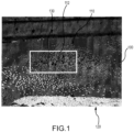
- Lightning strike protection film 100 may comprise a tow 110.
- Tow 110 is illustrated in the zero degree direction.
- the zero degree direction refers to a tow that is normal to the plane of the image, such that a cross-section of each carbon fiber 112 in the tow is represented by a circle in FIG. 1 .
- a tow fiber volume fraction of the tow 110 may be measured by computer analysis.
- An image of the tow 110 in the zero degree direction, such as the image shown in FIG. 1 may be captured.
- a representative section 130 of the tow 110 may be analyzed by a contrast program.
- the contrast program may measure the area of white circles representing carbon fibers 112, and divide the area of the carbon fibers by the total area of the section 130 in order to calculate the tow fiber volume fraction of the tow.
- tow 110 may comprise a tow fiber volume fraction of approximately 20%.
- the tow fiber volume fraction may be a function of the amount of CNTs grown in an intratow region between carbon fibers 112, because the CNTs may push the carbon fibers 112 apart, thus increasing the volume of the tow 110 and decreasing the tow fiber volume fraction of the tow 110.
- tow 120 may comprise a relatively high tow fiber volume fraction. This is visible as the carbon fibers 122 are densely packed together. The high tow fiber volume fraction may indicate that few or no CNTs are present between carbon fibers 122.
- tow fiber volume fraction a weight fraction of CNTs per unit weight of fiber substrate
- tow fiber volume fractions lower tow fiber volume fractions (representing more CNTs grown between carbon fibers) correlated to less damage from test lightning strikes.
- tow fiber volume fractions decrease below 10% and approach 5%, the volume of the tow may become too large to adequately fit within a surface film.
- tow fiber volume fractions lower than 5% may provide only incremental benefit in lessening damage from lightning strikes.
- tow fiber volume fractions of less than 45% such as between 10% - 20%, or in various embodiments between 5% - 40% were determined to adequately prevent damage from lightning strikes while balancing cost and manufacturing obstacles.
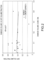
- a graph of the weight fraction of CNTs versus the volume of resulting damage from test lightning strikes is illustrated according to various embodiments.
- the surface area of damage and the maximum damage depth was measured to determine a volume damage for a 30kA test lightning strike.
- the weight fraction of CNTs varied from 7% to 45% in 19 sample composites, with the majority of weight fractions being between 20% and 40%.
- the R-squared value (with a value of 1.000 being a perfect correlation, and a value of 0.000 being zero correlation) was 0.0077.
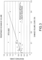
- FIG. 3 a graph of the surface resistance versus resulting damage from test lighting strikes is illustrated according to various embodiments.
- the surface resistance varied from 0.5 Ohms/square to 1.6 Ohms/square in the sample composites.
- the R-squared value was 0.4929.
- FIG. 4 a graph of the tow fiber volume fraction versus resulting damage from test lighting strikes is illustrated according to various embodiments.
- the tow fiber volume fraction varied from .08 to .44 in the sample composites.
- the R-squared value was 0.8373.
- the method may comprise activating the surfaces of carbon fibers in a carbon fiber tow (step 510).
- the interior carbon fibers i.e. the carbon fibers not located at the surface of the carbon fiber tow
- the activation of the surfaces may involve oxidizing the fibers to create small imperfections on the fiber surface, such as a pit or a crevice, on all (interior and exterior) fibers within the tow.
- the carbon fiber surfaces may be chemically treated to create these imperfections.
- the method may comprise adding a catalyst to the carbon fiber tow (step 520), such that the imperfections serve as preferential sites for the catalysts to be attached to the carbon fiber surfaces.
- the adding the catalyst may be performed by at least one of chemical vapor deposition, solution-precipitation, electrodeposition and submersing the carbon fiber tow in a catalyst solution.
- the method may include growing carbon nanotubes on the carbon fibers in the carbon fiber tow (step 530).
- the carbon nanotubes may be uniformly grown on the carbon fibers, such that the carbon nanotubes are located on both an external surface of the carbon fibers on the outer surface of the tow and on external surfaces of the carbon fibers within the tow.
- the growth of the carbon nanotubes may be controlled to reach a selected tow fiber volume fraction of the carbon tow (step 540).
- a tow fiber volume fraction may be decreased using more aggressive activation of the fiber surfaces to create more sites for CNT growth. Aggressive treatment of the surfaces may create a greater number of sites for catalyst seeding in the fiber tow. Aggressive activation may involve heat-treatment of the carbon fibers, oxidation of the fiber surfaces or chemical treatment, such as with acid.
- the substrates described above can be incorporated into or attached to substantially any type of structure requiring lightning strike protection and/or structural reinforcement.
- such films can be incorporated into or attached to an aircraft engine nacelle, fuselage, wing or vertical tail, a helicopter rotor blade or other helicopter component, or components or portions of such structures.
- they can be incorporated into or attached to other structures such as wind turbine blades and their support structures.
- Other uses will be apparent to those skilled in the art.
- references to "one embodiment”, “an embodiment”, “various embodiments”, etc. indicate that the embodiment described may include a particular feature, structure, or characteristic, but every embodiment may not necessarily include the particular feature, structure, or characteristic. Moreover, such phrases are not necessarily referring to the same embodiment. Further, when a particular feature, structure, or characteristic is described in connection with an embodiment, it is submitted that it is within the knowledge of one skilled in the art to affect such feature, structure, or characteristic in connection with other embodiments whether or not explicitly described. After reading the description, it will be apparent to one skilled in the relevant art(s) how to implement the disclosure in alternative embodiments.
Landscapes
- Chemical & Material Sciences (AREA)
- Engineering & Computer Science (AREA)
- Materials Engineering (AREA)
- Health & Medical Sciences (AREA)
- Manufacturing & Machinery (AREA)
- Chemical Kinetics & Catalysis (AREA)
- Medicinal Chemistry (AREA)
- Polymers & Plastics (AREA)
- Organic Chemistry (AREA)
- Aviation & Aerospace Engineering (AREA)
- Nanotechnology (AREA)
- Inorganic Chemistry (AREA)
- Carbon And Carbon Compounds (AREA)
- Elimination Of Static Electricity (AREA)
- Reinforced Plastic Materials (AREA)
Applications Claiming Priority (2)
| Application Number | Priority Date | Filing Date | Title |
|---|---|---|---|
| US14/261,880 US9834318B2 (en) | 2014-04-25 | 2014-04-25 | Lightning strike protection for composite components |
| EP15164375.6A EP2937376B1 (de) | 2014-04-25 | 2015-04-21 | Blitzschlagschutz für verbundbauteile |
Related Parent Applications (2)
| Application Number | Title | Priority Date | Filing Date |
|---|---|---|---|
| EP15164375.6A Division-Into EP2937376B1 (de) | 2014-04-25 | 2015-04-21 | Blitzschlagschutz für verbundbauteile |
| EP15164375.6A Division EP2937376B1 (de) | 2014-04-25 | 2015-04-21 | Blitzschlagschutz für verbundbauteile |
Publications (2)
| Publication Number | Publication Date |
|---|---|
| EP4234411A2 true EP4234411A2 (de) | 2023-08-30 |
| EP4234411A3 EP4234411A3 (de) | 2023-10-04 |
Family
ID=53189582
Family Applications (2)
| Application Number | Title | Priority Date | Filing Date |
|---|---|---|---|
| EP23177611.3A Withdrawn EP4234411A3 (de) | 2014-04-25 | 2015-04-21 | Blitzschlagschutz für verbundbauteile |
| EP15164375.6A Active EP2937376B1 (de) | 2014-04-25 | 2015-04-21 | Blitzschlagschutz für verbundbauteile |
Family Applications After (1)
| Application Number | Title | Priority Date | Filing Date |
|---|---|---|---|
| EP15164375.6A Active EP2937376B1 (de) | 2014-04-25 | 2015-04-21 | Blitzschlagschutz für verbundbauteile |
Country Status (2)
| Country | Link |
|---|---|
| US (2) | US9834318B2 (de) |
| EP (2) | EP4234411A3 (de) |
Families Citing this family (5)
| Publication number | Priority date | Publication date | Assignee | Title |
|---|---|---|---|---|
| US10329031B2 (en) * | 2016-06-17 | 2019-06-25 | Goodrich Corporation | Electricity dispersion for aircraft evacuation assemblies |
| CN110031104A (zh) * | 2018-01-11 | 2019-07-19 | 清华大学 | 面源黑体 |
| CN110031106B (zh) * | 2018-01-11 | 2021-04-02 | 清华大学 | 黑体辐射源 |
| CN110031107B (zh) * | 2018-01-11 | 2022-08-16 | 清华大学 | 黑体辐射源及黑体辐射源的制备方法 |
| CN110031108A (zh) * | 2018-01-11 | 2019-07-19 | 清华大学 | 黑体辐射源及黑体辐射源的制备方法 |
Family Cites Families (9)
| Publication number | Priority date | Publication date | Assignee | Title |
|---|---|---|---|---|
| EP1996465A2 (de) * | 2006-03-10 | 2008-12-03 | Goodrich Corporation | Schutz vor blitzschlägen von geringer dichte zur verwendung in flugzeugen |
| EP2022886B1 (de) * | 2006-05-02 | 2013-10-16 | Goodrich Corporation | Verfahren zur Herstellung nanoverstärkter Kohlenstofffasern sowie nanoverstärkte Kohlenstofffasern enthaltende Flugzeugkomponenten |
| US20100227134A1 (en) * | 2009-03-03 | 2010-09-09 | Lockheed Martin Corporation | Method for the prevention of nanoparticle agglomeration at high temperatures |
| AU2010259173B2 (en) * | 2009-04-24 | 2015-03-19 | Applied Nanostructured Solutions Llc | CNT-based signature control material |
| US8561934B2 (en) | 2009-08-28 | 2013-10-22 | Teresa M. Kruckenberg | Lightning strike protection |
| US20110123735A1 (en) | 2009-11-23 | 2011-05-26 | Applied Nanostructured Solutions, Llc | Cnt-infused fibers in thermoset matrices |
| AU2011256789A1 (en) * | 2010-02-02 | 2012-07-12 | Applied Nanostructured Solutions, Llc | Fiber containing parallel-aligned carbon nanotubes |
| US9511562B2 (en) * | 2012-07-03 | 2016-12-06 | Rohr, Inc. | Nanoreinforced films and laminates for aerospace structures |
| US20140356613A1 (en) * | 2013-05-31 | 2014-12-04 | Materials Sciences Corporation | Carbon nanotube studded carbon fiber tow and matrix prepreg |
-
2014
- 2014-04-25 US US14/261,880 patent/US9834318B2/en not_active Expired - Fee Related
-
2015
- 2015-04-21 EP EP23177611.3A patent/EP4234411A3/de not_active Withdrawn
- 2015-04-21 EP EP15164375.6A patent/EP2937376B1/de active Active
-
2017
- 2017-11-03 US US15/802,558 patent/US10392127B2/en active Active
Also Published As
| Publication number | Publication date |
|---|---|
| US9834318B2 (en) | 2017-12-05 |
| EP2937376A1 (de) | 2015-10-28 |
| US20150307206A1 (en) | 2015-10-29 |
| EP2937376B1 (de) | 2023-07-19 |
| US10392127B2 (en) | 2019-08-27 |
| US20180065758A1 (en) | 2018-03-08 |
| EP4234411A3 (de) | 2023-10-04 |
Similar Documents
| Publication | Publication Date | Title |
|---|---|---|
| EP2826809B1 (de) | Verbesserter Blitzschlagschutz | |
| US10392127B2 (en) | Lightning strike protection for composite components | |
| Alemour et al. | A review of using conductive composite materials in solving lightening strike and ice accumulation problems in aviation | |
| EP2022886B1 (de) | Verfahren zur Herstellung nanoverstärkter Kohlenstofffasern sowie nanoverstärkte Kohlenstofffasern enthaltende Flugzeugkomponenten | |
| Guo et al. | Simultaneously increasing the electrical conductivity and fracture toughness of carbon–fiber composites by using silver nanowires-loaded interleaves | |
| US8664573B2 (en) | CNT-based resistive heating for deicing composite structures | |
| EP2687364B1 (de) | Zusammengesetztes leitfähiges Blatt, Herstellungsverfahren und Verwendung davon | |
| CN107108010B (zh) | 包括纳米结构的纤维增强部件 | |
| US9771866B2 (en) | High temperature composite inlet | |
| US20110143087A1 (en) | Flame-resistant composite materials and articles containing carbon nanotube-infused fiber materials | |
| US9130363B2 (en) | Lightning strike protection means and fiber composite component | |
| JP2019060050A (ja) | 複合素材、プリプレグ、炭素繊維強化成形体、および複合素材の製造方法 | |
| CN116512724A (zh) | 用于复合层压体的表面膜 | |
| Nazarov | APPLICATION AND PROPERTIES OF POLYMER COMPOSITE CARBON FIBERS | |
| CN121284772A (zh) | 一种电热材料编织管状结构、电热材料编织布及电加热层结构 |
Legal Events
| Date | Code | Title | Description |
|---|---|---|---|
| PUAI | Public reference made under article 153(3) epc to a published international application that has entered the european phase |
Free format text: ORIGINAL CODE: 0009012 |
|
| STAA | Information on the status of an ep patent application or granted ep patent |
Free format text: STATUS: THE APPLICATION HAS BEEN PUBLISHED |
|
| AC | Divisional application: reference to earlier application |
Ref document number: 2937376 Country of ref document: EP Kind code of ref document: P |
|
| AK | Designated contracting states |
Kind code of ref document: A2 Designated state(s): AL AT BE BG CH CY CZ DE DK EE ES FI FR GB GR HR HU IE IS IT LI LT LU LV MC MK MT NL NO PL PT RO RS SE SI SK SM TR |
|
| REG | Reference to a national code |
Ref country code: DE Ref legal event code: R079 Free format text: PREVIOUS MAIN CLASS: B64D0045020000 Ipc: C08J0005000000 |
|
| PUAL | Search report despatched |
Free format text: ORIGINAL CODE: 0009013 |
|
| AK | Designated contracting states |
Kind code of ref document: A3 Designated state(s): AL AT BE BG CH CY CZ DE DK EE ES FI FR GB GR HR HU IE IS IT LI LT LU LV MC MK MT NL NO PL PT RO RS SE SI SK SM TR |
|
| RIC1 | Information provided on ipc code assigned before grant |
Ipc: B64D 45/02 20060101ALI20230830BHEP Ipc: C08J 5/06 20060101ALI20230830BHEP Ipc: C08J 5/04 20060101ALI20230830BHEP Ipc: C08J 5/00 20060101AFI20230830BHEP |
|
| STAA | Information on the status of an ep patent application or granted ep patent |
Free format text: STATUS: REQUEST FOR EXAMINATION WAS MADE |
|
| 17P | Request for examination filed |
Effective date: 20240403 |
|
| RBV | Designated contracting states (corrected) |
Designated state(s): AL AT BE BG CH CY CZ DE DK EE ES FI FR GB GR HR HU IE IS IT LI LT LU LV MC MK MT NL NO PL PT RO RS SE SI SK SM TR |
|
| STAA | Information on the status of an ep patent application or granted ep patent |
Free format text: STATUS: THE APPLICATION IS DEEMED TO BE WITHDRAWN |
|
| 18D | Application deemed to be withdrawn |
Effective date: 20251101 |