EP4234332A1 - Collapsible vehicle camera arm assembly - Google Patents
Collapsible vehicle camera arm assembly Download PDFInfo
- Publication number
- EP4234332A1 EP4234332A1 EP23157350.2A EP23157350A EP4234332A1 EP 4234332 A1 EP4234332 A1 EP 4234332A1 EP 23157350 A EP23157350 A EP 23157350A EP 4234332 A1 EP4234332 A1 EP 4234332A1
- Authority
- EP
- European Patent Office
- Prior art keywords
- detent
- detent ring
- arcuate distance
- projections
- carrier base
- Prior art date
- Legal status (The legal status is an assumption and is not a legal conclusion. Google has not performed a legal analysis and makes no representation as to the accuracy of the status listed.)
- Granted
Links
Images




Classifications
-
- B—PERFORMING OPERATIONS; TRANSPORTING
- B60—VEHICLES IN GENERAL
- B60R—VEHICLES, VEHICLE FITTINGS, OR VEHICLE PARTS, NOT OTHERWISE PROVIDED FOR
- B60R1/00—Optical viewing arrangements; Real-time viewing arrangements for drivers or passengers using optical image capturing systems, e.g. cameras or video systems specially adapted for use in or on vehicles
- B60R1/02—Rear-view mirror arrangements
- B60R1/06—Rear-view mirror arrangements mounted on vehicle exterior
- B60R1/0605—Rear-view mirror arrangements mounted on vehicle exterior specially adapted for mounting on trucks, e.g. by C-shaped support means
- B60R1/0617—Rear-view mirror arrangements mounted on vehicle exterior specially adapted for mounting on trucks, e.g. by C-shaped support means foldable along the vehicle, e.g. in case of external force applied thereon
-
- B—PERFORMING OPERATIONS; TRANSPORTING
- B60—VEHICLES IN GENERAL
- B60R—VEHICLES, VEHICLE FITTINGS, OR VEHICLE PARTS, NOT OTHERWISE PROVIDED FOR
- B60R11/00—Arrangements for holding or mounting articles, not otherwise provided for
- B60R11/04—Mounting of cameras operative during drive; Arrangement of controls thereof relative to the vehicle
-
- B—PERFORMING OPERATIONS; TRANSPORTING
- B60—VEHICLES IN GENERAL
- B60R—VEHICLES, VEHICLE FITTINGS, OR VEHICLE PARTS, NOT OTHERWISE PROVIDED FOR
- B60R1/00—Optical viewing arrangements; Real-time viewing arrangements for drivers or passengers using optical image capturing systems, e.g. cameras or video systems specially adapted for use in or on vehicles
- B60R1/20—Real-time viewing arrangements for drivers or passengers using optical image capturing systems, e.g. cameras or video systems specially adapted for use in or on vehicles
- B60R1/22—Real-time viewing arrangements for drivers or passengers using optical image capturing systems, e.g. cameras or video systems specially adapted for use in or on vehicles for viewing an area outside the vehicle, e.g. the exterior of the vehicle
- B60R1/23—Real-time viewing arrangements for drivers or passengers using optical image capturing systems, e.g. cameras or video systems specially adapted for use in or on vehicles for viewing an area outside the vehicle, e.g. the exterior of the vehicle with a predetermined field of view
- B60R1/25—Real-time viewing arrangements for drivers or passengers using optical image capturing systems, e.g. cameras or video systems specially adapted for use in or on vehicles for viewing an area outside the vehicle, e.g. the exterior of the vehicle with a predetermined field of view to the sides of the vehicle
-
- G—PHYSICS
- G03—PHOTOGRAPHY; CINEMATOGRAPHY; ANALOGOUS TECHNIQUES USING WAVES OTHER THAN OPTICAL WAVES; ELECTROGRAPHY; HOLOGRAPHY
- G03B—APPARATUS OR ARRANGEMENTS FOR TAKING PHOTOGRAPHS OR FOR PROJECTING OR VIEWING THEM; APPARATUS OR ARRANGEMENTS EMPLOYING ANALOGOUS TECHNIQUES USING WAVES OTHER THAN OPTICAL WAVES; ACCESSORIES THEREFOR
- G03B17/00—Details of cameras or camera bodies; Accessories therefor
- G03B17/56—Accessories
- G03B17/561—Support related camera accessories
-
- B—PERFORMING OPERATIONS; TRANSPORTING
- B60—VEHICLES IN GENERAL
- B60R—VEHICLES, VEHICLE FITTINGS, OR VEHICLE PARTS, NOT OTHERWISE PROVIDED FOR
- B60R11/00—Arrangements for holding or mounting articles, not otherwise provided for
- B60R2011/0001—Arrangements for holding or mounting articles, not otherwise provided for characterised by position
- B60R2011/004—Arrangements for holding or mounting articles, not otherwise provided for characterised by position outside the vehicle
-
- B—PERFORMING OPERATIONS; TRANSPORTING
- B60—VEHICLES IN GENERAL
- B60R—VEHICLES, VEHICLE FITTINGS, OR VEHICLE PARTS, NOT OTHERWISE PROVIDED FOR
- B60R11/00—Arrangements for holding or mounting articles, not otherwise provided for
- B60R2011/0042—Arrangements for holding or mounting articles, not otherwise provided for characterised by mounting means
- B60R2011/008—Adjustable or movable supports
- B60R2011/0082—Adjustable or movable supports collapsible, e.g. for storing after use
Definitions
- the first detent ring is in an intermeshing arrangement when the second detent ring in a first rotational position and in a non-intermeshing arrangement when in a second rotational position.
- a first stop surface fixed relative to the carrier base is in engagement with a stop fixed relative to the support arm.
- the plurality of first projections may include at least two first projections each extending a first arcuate distance around the first detent ring.
- a single first projection may extend a second arcuate distance around the first detent ring.
- the second arcuate distance may be greater than the first arcuate distance.
- the one of the at least two first projections and the single first projection may be configured to intermesh with the single second channel.
- each of the five projections 60 include a projection surface defining an axially outer surface of the projection 60 and each of the five channels 62 include a channel surface defining an axially outer surface of the channel 62.
- the projection surfaces and the channel surfaces are planar. However, the projection surfaces and the channel surfaces could be curved with a varying distance from the body portion of the carrier base 30. The above arcuate distance for the single projection 60B in degrees are in relation to the axially outer surface of the single projection 60B.
- a first stop 64 and a second stop 66 are located radially outward from the carrier detent ring 46 relative to axis S on the carrier base 30.
- a stop surface 64A, 66A on the first and second projections 64, 66, respectively, are located in a radially overlapping position relative to the axis SR.
- a stop projection 68 is located on the support arm 38 and positioned to contact the stop surfaces 64A when the support arm 38 is rotated as shown in Figure 8A and the stop surface 66B when the support arm 38 is rotated as shown in Figure 7A .
- the interaction between the first and second projections 64, 66 and the stop projection 68 prevents over rotation of the support arm 38 relative to the carrier base 30.
- the first and second stop projections 64, 66 and the stop projection 68 are also positioned to prevent intermeshing of the carrier detent ring 46 with the support detent ring 48.
Landscapes
- Engineering & Computer Science (AREA)
- Mechanical Engineering (AREA)
- Multimedia (AREA)
- Physics & Mathematics (AREA)
- General Physics & Mathematics (AREA)
- Accessories Of Cameras (AREA)
- Pivots And Pivotal Connections (AREA)
Abstract
Description
- This application relates to camera mirror arm assembly, and more particularly, to a foldable camera mirror assembly for use in a commercial truck, for example.
- Foldable camera mirror assemblies can be motorized or manually operated. With a motorized foldable camera mirror system, a drive motor must be located in a portion of assembly and are usually located adjacent a pivotable joint between a vehicle fixed housing and a pivotable housing. Conversely, manually operated foldable camera mirror systems do not include a drive motor and are generally pivoted by a user of the vehicle to place the assembly in a desired position.
- An aspect of the present disclosure relates to a vehicle arm assembly. The vehicle arm assembly includes a carrier base for attaching to a vehicle. A support arm is rotatably mounted relative to the carrier base. A first detent ring includes a plurality of first detent projections circumferentially offset by a plurality of first detent channels. A second detent ring includes a plurality of second detent projections circumferentially offset by a plurality of second detent channels. The first detent ring is fixed relative to one of the carrier base or the support arm. The second detent ring is fixed relative to the other of the carrier base or the support ring. The first detent ring is in an intermeshing arrangement when the second detent ring in a first rotational position and in a non-intermeshing arrangement when in a second rotational position. In the second rotational position a first stop surface fixed relative to the carrier base is in engagement with a stop fixed relative to the support arm.
- The plurality of first projections may include at least two first projections each extending a first arcuate distance around the first detent ring. A single first projection may extend a second arcuate distance around the first detent ring. The second arcuate distance may be greater than the first arcuate distance.
- The single one of the plurality of first detent projection and one of the at least two first projections may together extend an arcuate distance of at least 60 degrees around the first detent ring. The single one of the plurality of first detent projection and one of the at least two first projections may together extend an arcuate distance of less than 120 degrees around the first detent ring. The single one of the plurality of first detent projection and one of the at least two first projections may together extend an arcuate distance of at least 60 degrees and less than 120 degrees around the first detent ring.
- The plurality of second detent channels may include a first set of second channels that extend for a first arcuate length. A single second channel may extend a third arcuate distance. The third arcuate distance may be greater than the first arcuate distance.
- The third arcuate distance may be greater than second arcuate distance.
- The one of the at least two first projections and the single first projection may be configured to intermesh with the single second channel.
- The second single channel may extend an arcuate distance of at least 60 degrees around the second detent ring. The second single channel may extend an arcuate distance of less than 120 degrees around the second detent ring. The second single channel may extend an arcuate distance of at least 60 degrees and less than 120 degrees around the second detent ring.
- The second single channel may extend an arcuate distance of at least 75 degrees around the second detent ring. The second single channel may extend an arcuate distance of less than 105 degrees around the second detent ring. The second single channel may extend an arcuate distance of at least 75 degrees and less than 105 degrees around the second detent ring.
- The second detent ring may include a radially inner wall and a radially outer wall that creates recessed area for the plurality of second projections and the plurality of second channels.
- Each of the plurality of first channels may include an axially outer surface and each of the plurality of first projections may include an axially outer surface. The planar surface of each of the plurality of first channels may be connected to an adjacent one of the plurality of first projections by a connecting planar surface that is transverse to the channel planar surface and the projection planar surface.
- The first detent ring may be integrally formed as a unitary piece with the one of the carrier base or the support arm. The second detent ring may be integrally formed as a unitary piece with the other of the carrier base or the support arm.
- The first detent ring may be separately formed and connected, mounted, fixed etc. (permanently or removably) to or with the one of the carrier base or the support arm. The second detent ring may be separately formed and connected, mounted, fixed (permanently or removably) to or with the other of the carrier base or the support arm.
- The first detent ring may be removably attached to one of the carrier base or the support arm. The second detent ring may be removably attached to the other of the carrier base or the support arm.
- At least one camera may be fixed relative to the support arm.
- An aspect of the present disclosure relates to a method of operating a vehicle arm assembly. The method includes rotating a support arm including one of a first detent ring or a second detent ring relative to a carrier base having the other of the first detent ring or the second detent ring. The first detent ring is configured to intermesh with the second detent ring. Rotation of the support arm is limited relative to the carrier base in a first rotational direction with a first stop surface fixed relative to the carrier base engaging a stop fixed relative to the support arm. The first detent ring and the second detent ring are in a non-intermeshed relationship when the stop engages the first stop surface.
- The first detent ring may include a plurality of first channels separating a plurality of first projections. The plurality of first projections may include at least two first projections each extending a first arcuate distance around the first detent ring. A single first projection may extend a second arcuate distance around the first detent ring. The second arcuate distance may be greater than the first arcuate distance.
- The single first projection, one of the first channels, and one of the at least two first projections may extend an arcuate distance of at least 60 degrees around the first detent ring. The single first projection, one of the first channels, and one of the at least two first projections may extend an arcuate distance of less than 120 degrees around the first detent ring. The single first projection, one of the first channels, and one of the at least two first projections may extend an arcuate distance of at least 60 degrees and less than 120 degrees around the first detent ring.
- The second detent ring may include a plurality of second detent channels have a first set of second detent channels that extend for the first arcuate distance. A single second detent channel may extend a third arcuate distance. The third arcuate distance may be greater than the first arcuate distance.
- The single second detent channel may extend an arcuate distance of at least 60 degrees around the second detent ring. The single second detent channel may extend an arcuate distance of less than 120 degrees around the second detent ring. The single second detent channel may extend an arcuate distance of at least 60 degrees and less than 120 degrees around the second detent ring.
- The single second detent channel may extend an arcuate distance of at least 75 degrees around the second detent ring. The single second detent channel may extend an arcuate distance of less than 105 degrees around the second detent ring. The single second detent channel may extend an arcuate distance of at least 75 degrees and less than 105 degrees around the second detent ring.
- The method may comprise limiting rotation of the support arm relative to the carrier base in a second rotational direction with a second stop surface fixed relative to the carrier base engaging the stop fixed relative to the support arm. The first detent ring and the second detent ring may be in a non-intermeshing relationship when the stop engages the second stop surface.
- Features defined in relation to one aspect may be provided in combination with any other aspect.
- The various features and advantages of the present disclosure will become apparent to those skilled in the art from the following detailed description. The drawings that accompany the detailed description can be briefly described as follows.
-
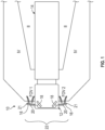
Figure 1 is a schematic top elevation view of a commercial truck with a camera mirror system (CMS) providing Class II and Class IV views. -
Figure 2 is a perspective view of an arm assembly. -
Figure 3 is a cross-section view of the camera arm assembly ofFigure 2 without fairings. -
Figure 4 is a perspective view of a carrier base of the arm assembly ofFigure 2 . -
Figure 5 is a bottom view of a support arm of the camera arm assembly ofFigure 2 . -
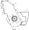
Figure 6A is a top view of the support arm ofFigure 5 mounted for rotation about the carrier base ofFigure 4 . -
Figure 6B illustrates a plan view of a support detent on the support arm in engagement with a carrier detent on the carrier base with the support arm and the carrier base in the position shown inFigure 6A . -
Figure 7A illustrates the support arm in an extended position relative to carrier base. -
Figure 7B illustrates a plan view of the support detent on the support arm in engagement with the carrier detent on the carrier base with the support arm and the carrier base in the position shown inFigure 7A . -
Figure 8A illustrates the support arm in a retracted position relative to the carrier base. -
Figure 8B illustrates a plan view of the support detent on the support arm in engagement with the carrier detent on the carrier base with the support arm and the carrier base in the position shown inFigure 8A . - A schematic view of a
commercial vehicle 10 is illustrated inFigure 1 . Thevehicle 10 includes avehicle cab 12 for towing atrailer 14. Driver and passengerside arm assemblies 16 are mounted to thevehicle cab 12, such as a camera arm assembly. If desired, thearm assemblies 16 may include conventional mirrors integrated with them as well. First andsecond displays 18 are arranged on each of the driver and passenger sides within thevehicle cab 12 near the A-pillars to display Class II and Class IV views on each side of thevehicle 10. - A rearward facing
camera 20 is arranged within eacharm assembly 16. Thecameras 20 provide a field of view FOV1, FOV2 that includes at least one of the Class II and Class IV views. Multiple cameras also may be used on eacharm assembly 16, if desired. Thesystem 10 may provide one or more cameras directed at the Class V and Class VI views instead or additionally. - As shown in
Figure 2 , thearm assembly 16 includes a contoured profile that contributes to a reduction in aerodynamic drag on thevehicle 10 during operation. Thearm assembly 16 includes acarrier base 30 for attaching to thevehicle cab 12 and a pivotingportion 32 that pivots relative to thecarrier base 30. The pivotingportion 32 supports at least one of the rearward facingcamera 20 or aconventional mirror 21 adjacent a distal end of thearm assembly 16. Alternatively, thearm assembly 16 could be used with only themirror 21 and not thecamera 20. - The pivoting
portion 32 also includes anupper fairing 34 and alower fairing 36 that enclose a support arm 38 (Figures 3 and5 ). Thesupport arm 38 forms a pivotable connection with thecarrier base 30 as will be described in greater detail below. Because thearm assembly 16 is manually pivoted between a retracted (Figures 8A ) and an extended position (Figures 7A ), it does not include a motor to pivot the pivotingportion 32 relative to thecarrier base 30. Additionally, thearm assembly 16 in the vicinity of the connection between the pivotingportion 32 and the carrier base 30 (SeeFigures 2 and3 ) includes a smaller vertical dimension and therefore includes a smaller leading edge area. This reduces drag on thearm assembly 16 and improves fuel efficiency of thevehicle 10. In the illustrated example, a vertical height of thearm assembly 16 in the vicinity of the pivot axis P is between 50 mm and 70 mm (1.97 inches and 2.76 inches). - As shown in
Figure 3 , asupport detent ring 48 on thesupport arm 38 engages acarrier detent ring 46 on thecarrier base 30 to allow thesupport arm 38 in the pivotingportion 32 to be selectively rotated relative to thecarrier base 30 into one of a multiple predetermined positions. Thecarrier detent ring 46 and thesupport detent ring 48 are biased toward each other with aspring 52, such as a helical spring, to encourage thecarrier detent ring 46 to move into an intermeshing position with thesupport detent ring 48. - To provide the biasing force, the
spring 52 engages aretainer disk 45 fixed relative to thecarrier base 30 on a first axial end and thesupport arm 38 on an opposite second axial end. Theretainer disk 45 is secured relative to thecarrier base 30 with afastener 40 having a head engaging thecarrier base 30 and a shaft extending through a passage on acentral shaft 50. Thecentral shaft 50 extends from thecarrier base 30. A distal end of thefastener 40 is threaded and located outside of the passage on thecentral shaft 50. Theretainer disk 45 includes a central opening for accepting thefastener 40 and anut 42 engages the threaded distal end of thefastener 40 and theretainer disk 45 to secure theretainer disk 45 relative to thecarrier base 30. - As shown in
Figures 6A ,7A , and8A , thesupport arm 38 is allowed to selectively pivot or rotate relative to thecarrier base 30 through the intermeshing ofcarrier detent ring 46 and thesupport detent ring 48. The force generated by thespring 52 provides a biasing force to move thecarrier detent ring 46 into the intermeshing arrangement with thesupport detent ring 48. However, this force is overcome by pivoting thesupport arm 38 which compresses thespring 52. - In the illustrated example of
Figure 4 , thecarrier detent ring 46 includes a ring formed by a cylindrical wall that extends from a body portion of thecarrier base 30. Thecarrier detent ring 46 can be integrally formed with thecarrier base 30 or thecarrier detent ring 46 can be removably attached to thecarrier base 30. A distal end of thecarrier detent ring 46 includes a plurality ofprojections 60 that are circumferentially spaced or offset from adj acentprojections 60 by a corresponding one of a plurality ofchannels 62. Therefore, theprojections 60 are located at a distal end of the cylindrical wall at a greater distance from thecarrier base 30 than thechannels 62. - The
projections 60 include a first set ofprojections 60A extending a first arcuate distance relative to a central longitudinal axis S of thecentral shaft 50 and a secondsingle projection 60B that extends a second arcuate distance relative to the axis S. Also, each of thechannels 62 separating theprojections 60A extend for a common or singular arcuate distance relative to the axis S. Additionally, the secondsingular projection 60B extends for an arcuate distance of between 40 and 60 degrees around thecarrier detent ring 46 relative to the axis S. Furthermore, the cylindrical wall including theprojections 60 and thechannels 62 are spaced from thecentral shaft 50 to accommodate thespring 52. In this disclosure, arcuate distances have a single or common radial distance relative to an axis unless stated otherwise. - In the illustrated example, each of the five
projections 60 include a projection surface defining an axially outer surface of theprojection 60 and each of the fivechannels 62 include a channel surface defining an axially outer surface of thechannel 62. In the illustrated example, the projection surfaces and the channel surfaces are planar. However, the projection surfaces and the channel surfaces could be curved with a varying distance from the body portion of thecarrier base 30. The above arcuate distance for thesingle projection 60B in degrees are in relation to the axially outer surface of thesingle projection 60B. - Adjacent projection surfaces of the
projections 60 and channel surfaces of thechannels 62 are connected by one of a plurality of transition surfaces 65. The transition surfaces 65 are transverse to both the projection surfaces and the channel surfaces not perpendicular to either one. This facilitates rotational movement of thecarrier detent ring 46 with thesupport detent ring 48 when pivoting thesupport arm 38 relative to thecarrier base 30 because the transition surfaces 65 operate as ramps. - As shown in
Figures 3 and5 , thesupport detent ring 48 extends from a bottom side of thesupport arm 38. Thesupport detent ring 48 faces towards thecarrier detent ring 46 when assembled. Thesupport arm 38 includes a proximal end having a curvature to facilitate pivoting relative to thecarrier base 30 and a distal end for securing acamera 20 ormirror 21. In the illustrated example, thesupport detent ring 48 is integrally formed with thesupport arm 38. However, in another example, thesupport detent ring 48 is removably attached to thesupport arm 38. - In the illustrated example, the
support detent ring 48 includes radially inner and outercylindrical walls support detent ring 48. The axis SR is colinear with the axis P and the axis S. In the illustrated example, the radially inner andouter walls projections 76 andchannels 78 located in a recessed area between the radially inner andouter walls outer walls support detent ring 48 and thecarrier detent ring 46. - Each of the four
projections 76 include a projection surface defining an axially outer most surface of theprojection 76 and each of the fourchannels 78 include an axially outer most surface of thechannel 78. Adjacent axially outer most surfaces of theprojections 76 andchannels 78 are connected by atransition surface 80. The transition surfaces 80 are transverse to both the outer surfaces of theprojections 76 and thechannels 78 and theprojections 76 and not perpendicular. - In the illustrated example, a first set of
channels 78A of thechannels 78 extend for a common or singular first arcuate distance relative the axis SR of thesupport detent ring 48. Asecond channel 78B of thechannels 78 extends for a second arcuate distance about the axis SR with the second arcuate distance extending between 60 and 120 degrees around the axis SR. In another example, the second arcuate distance extends between 75 and 105 degrees around thesupport detent ring 48. In the above example, the above arcuate distances in degrees correspond to the axially outer most surface of thesecond channel 78B. - Furthermore, when the
support arm 38 is in a normal operating position relative to thecarrier base 30 as shown inFigure 6A , the secondsingular projection 60B and one of theprojections 60A are located in thesecond channel 78B as shown inFigure 6B . Theprojection 60B located in thechannel 78B is immediately adjacent one of theprojections 76. - When the
support arm 38 is pivoted about thecarrier base 30 in an upstream direction or towards a leading edge of theassembly 16 as shown inFigure 7A , theprojection 60B will engage the outer surface of at least one of theprojections 76 on the carrier base. This prevents thecarrier detent ring 46 from intermeshing with thesupport detent ring 48 because theprojection 60B includes a larger circumferential distance than thechannels 78A as shown inFigure 7B . - When the
support arm 38 is pivoted about thecarrier base 30 in a downstream direction as shown inFigure 8A , theprojection 60B will engage the outer surface of at least one of theprojections 76 on thecarrier base 30. This prevents thecarrier detent ring 46 from intermeshing with thesupport detent ring 48 because theprojection 60B includes a larger circumferential distance than thechannels 78A as shown inFigure 8B . - As shown in
Figure 4 , afirst stop 64 and a second stop 66 are located radially outward from thecarrier detent ring 46 relative to axis S on thecarrier base 30. In the illustrated example, astop surface second projections 64, 66, respectively, are located in a radially overlapping position relative to the axis SR. A stop projection 68 is located on thesupport arm 38 and positioned to contact the stop surfaces 64A when thesupport arm 38 is rotated as shown inFigure 8A and the stop surface 66B when thesupport arm 38 is rotated as shown inFigure 7A . The interaction between the first andsecond projections 64, 66 and the stop projection 68 prevents over rotation of thesupport arm 38 relative to thecarrier base 30. The first andsecond stop projections 64, 66 and the stop projection 68 are also positioned to prevent intermeshing of thecarrier detent ring 46 with thesupport detent ring 48. - Additionally, the first and
second projections 64, 66 and the stop projection 68 are positioned such that when the stop projection 68 engages either of the first orsecond projections 64, 66, thecarrier detent ring 46 and thesupport detent ring 48 are not in an intermeshing position. In particular, the outer surface of theprojections 60 on thecarrier detent ring 46 and the outer surfaces of theprojections 76 on thesupport detent ring 48 are in engagement with each other. One feature of this configuration is that when thesupport arm 38 is fully extended and at a greatest distance for the operator of the vehicle to reach, thesupport arm 38 is not restricted by the force needed to move thecarrier detent ring 46 and thesupport detent ring 48 out of an intermeshing engagement. In particular, the force needed to move thesupport arm 38 will mostly be from the frictional forces between the outer surfaces on theprojections - Although the different non-limiting examples are illustrated as having specific components, the examples of this disclosure are not limited to those particular combinations. It is possible to use some of the components or features from any of the non-limiting examples in combination with features or components from any of the other non-limiting examples.
- It should be understood that like reference numerals identify corresponding or similar elements throughout the several drawings. It should also be understood that although a particular component arrangement is disclosed and illustrated in these exemplary embodiments, other arrangements could also benefit from the teachings of this disclosure.
- The foregoing description shall be interpreted as illustrative and not in any limiting sense. A worker of ordinary skill in the art would understand that certain modifications could come within the scope of this disclosure. For these reasons, the following claim should be studied to determine the true scope and content of this disclosure.
Claims (15)
- A vehicle arm assembly comprising:a carrier base for attaching to a vehicle;support arm rotatably mounted relative to the carrier base;a first detent ring including a plurality of first detent projections circumferentially offset by a plurality of first detent channels; anda second detent ring including a plurality of second detent projections circumferentially offset by a plurality of second detent channels;wherein the first detent ring is fixed relative to one of the carrier base or the support arm and the second detent ring is fixed relative to the other of the carrier base or the support ring;wherein the first detent ring is in an intermeshing arrangement when the second detent ring in a first rotational position and in a non-intermeshing arrangement when in a second rotational position; andwherein in the second rotational position a first stop surface fixed relative to the carrier base is in engagement with a stop fixed relative to the support arm.
- The assembly of claim 1, wherein the plurality of first projections include at least two first projections each extending a first arcuate distance around the first detent ring and a single one of the first projections extending a second arcuate distance around the first detent ring with the second arcuate distance being greater than the first arcuate distance.
- The assembly of claim 2, wherein the single one of the plurality of first detent projections and one of the at least two first projections together extend an arcuate distance of at least 60 degrees and less than 120 degrees around the first detent ring.
- The assembly of claim 2 or 3, wherein the plurality of second detent channels includes a first set of second channels extending for a first arcuate length and a single second channel extending a third arcuate distance and the third arcuate distance is greater than the first arcuate distance.
- The assembly of claim 4, wherein the third arcuate distance is greater than second arcuate distance.
- The assembly of any one of claims 2 to 5, wherein the one of the at least two first projections and the single first projection are configured to intermesh with the single second channel.
- The assembly of any one of claims 4 to 6, wherein the second single channel extends an arcuate distance of at least 60 degrees and less than 120 degrees around the second detent ring.
- The assembly of any one of claims 4 to 7, wherein the second single channel extends an arcuate distance of at least 75 degrees and less than 105 degrees around the second detent ring.
- The assembly of any preceding claim, wherein the second detent ring includes a radially inner wall and a radially outer wall that creates recessed area for the plurality of second projections and the plurality of second channels.
- The assembly of any preceding claim, wherein each of the plurality of first channels include an axially outer surface and each of the plurality of first projections include an axially outer surface and the planar surface of each of the plurality of first channels is connected to an adjacent one of the plurality of first projections by a connecting planar surface that is transverse to the channel planar surface and the projection planar surface.
- The assembly of any preceding claim, wherein the first detent ring is integrally formed as a unitary piece with the one of the carrier base or the support arm and the second detent ring is integrally formed as a unitary piece with the other of the carrier base or the support arm.
- The assembly of any preceding claim, wherein the first detent ring is removably attached to one of the carrier base or the support arm and the second detent ring is removably attached to the other of the carrier base or the support arm.
- The assembly of any preceding claim, further comprising at least one camera fixed relative to the support arm.
- A method of operating the vehicle arm assembly of any preceding claim, comprising:rotating a support arm including one of the first detent ring or the second detent ring relative to the carrier base having the other of the first detent ring or the second detent ring, wherein the first detent ring is configured to intermesh with the second detent ring; andlimiting rotation of the support arm relative to the carrier base in a first rotational direction with the first stop surface engaging the stop, wherein the first detent ring and the second detent ring are in a non-intermeshed relationship when the stop engages the first stop surface.
- The method of claim 14, wherein the plurality of first detent projections include at least two first projections each extending a first arcuate distance around the first detent ring and a single first detent projection extending a second arcuate distance around the first detent ring with the second arcuate distance being greater than the first arcuate distance, wherein the plurality of second detent channels have a first set of second detent channels extending for the first arcuate distance and a single second detent channel extending a third arcuate distance and the third arcuate distance is greater than the first arcuate distance.
Applications Claiming Priority (1)
| Application Number | Priority Date | Filing Date | Title |
|---|---|---|---|
| US17/679,868 US11958419B2 (en) | 2022-02-24 | 2022-02-24 | Collapsible vehicle camera arm assembly |
Publications (2)
| Publication Number | Publication Date |
|---|---|
| EP4234332A1 true EP4234332A1 (en) | 2023-08-30 |
| EP4234332B1 EP4234332B1 (en) | 2024-09-18 |
Family
ID=85283620
Family Applications (1)
| Application Number | Title | Priority Date | Filing Date |
|---|---|---|---|
| EP23157350.2A Active EP4234332B1 (en) | 2022-02-24 | 2023-02-17 | Collapsible vehicle camera arm assembly |
Country Status (3)
| Country | Link |
|---|---|
| US (1) | US11958419B2 (en) |
| EP (1) | EP4234332B1 (en) |
| CN (1) | CN116639054A (en) |
Citations (1)
| Publication number | Priority date | Publication date | Assignee | Title |
|---|---|---|---|---|
| US20200088232A1 (en) * | 2017-09-19 | 2020-03-19 | SMR Patents S.à.r.l. | Locking ring, rear view device and vehicle |
Family Cites Families (61)
| Publication number | Priority date | Publication date | Assignee | Title |
|---|---|---|---|---|
| GB1243179A (en) | 1967-10-03 | 1971-08-18 | Unimec Designs Ltd | Improvements relating to mirror devices for motor vehicles |
| CA861762A (en) | 1969-01-10 | 1971-01-26 | Dominion Auto Accessories Limited | Hinge joint assemblies |
| US4186905A (en) | 1975-06-09 | 1980-02-05 | Dominion Auto Accessories Limited | Retractable truck mirror |
| JPH06953U (en) | 1992-06-09 | 1994-01-11 | 市光工業株式会社 | Rear view device for automobiles |
| JPH09175272A (en) | 1995-12-28 | 1997-07-08 | Ichikoh Ind Ltd | Vehicle surveillance camera |
| DE19906150A1 (en) | 1999-02-10 | 2000-09-07 | Magna Reflex Holding Gmbh | Vehicle exterior mirror and method for its control |
| US6286968B1 (en) | 1999-09-07 | 2001-09-11 | Lang-Mekra North America, Llc | Mirror mounting assembly with stop feature |
| DE19961313B4 (en) | 1999-12-18 | 2005-06-02 | Bayerische Motoren Werke Ag | Camera device for a vehicle |
| AU2002307484B2 (en) | 2001-04-20 | 2007-04-26 | Camera Dynamics Inc. | Heavy-duty stabilized camera head with camera position sensing |
| KR100858406B1 (en) | 2001-10-30 | 2008-09-11 | 쉐프네커 비젼 시스템즈 오스트레일리아 프로프라이어터리 리미티드 | Power Telescoping Vehicle Mirror Assembly |
| DE10218228A1 (en) | 2002-04-24 | 2003-11-06 | Volkswagen Ag | Motor vehicle video camera operational checking method in which video data are subjected to plausibility testing in conjunction with other sensor data, such as yaw rate, transverse acceleration, vehicle speed, etc. |
| JP2003320898A (en) | 2002-04-26 | 2003-11-11 | Sony Corp | Vehicle side mirror device |
| AU2003290791A1 (en) | 2002-11-14 | 2004-06-15 | Donnelly Corporation | Imaging system for vehicle |
| DE102004039450A1 (en) | 2004-08-13 | 2006-03-09 | 2W Technische Informations Gmbh | System to assist the driver in parking a motor vehicle has cameras concealed in the front and rear, linked to an interior display, with a control to open the camera covers and activate the display |
| EP1647867A1 (en) | 2004-10-11 | 2006-04-19 | The Swatch Group Management Services AG | Magnifying device for timepieces |
| EP1736360A1 (en) | 2005-06-23 | 2006-12-27 | Mazda Motor Corporation | Blind-Spot detection system for vehicle |
| DE102008046980B3 (en) | 2008-09-11 | 2010-06-02 | Mekra Lang Gmbh & Co. Kg | Mirror mount for attaching a mirror to a vehicle and mirror with such a mirror mount |
| JP2011003117A (en) | 2009-06-22 | 2011-01-06 | Central Motor Co Ltd | Backward visual recognition support system |
| KR101199070B1 (en) | 2009-12-03 | 2012-11-07 | 현대자동차주식회사 | Shifting Range Sensing Apparatus |
| DE102010005638A1 (en) | 2010-01-25 | 2011-07-28 | Valeo Schalter und Sensoren GmbH, 74321 | Method for indicating image of vehicle surrounding on display unit in vehicle, involves arranging camera at or in outer mirror of vehicle for receiving pictures of vehicle surrounding |
| US9827913B2 (en) | 2010-02-10 | 2017-11-28 | Magna Mirrors Of America, Inc. | Exterior rearview mirror assembly |
| CN202088981U (en) | 2011-05-31 | 2011-12-28 | 伟速达(中国)汽车安全系统有限公司 | Automobile rearview camera device controller |
| US8336845B1 (en) | 2011-07-13 | 2012-12-25 | Lang-Mekra North America, Llc | Pivoting detent joint for a vehicle mirror assembly |
| US8544151B2 (en) | 2011-11-22 | 2013-10-01 | Lang-Mekra North America, Llc | Engaging surfaces arrangement for a pivoting detent joint |
| US8830317B2 (en) | 2011-11-23 | 2014-09-09 | Robert Bosch Gmbh | Position dependent rear facing camera for pickup truck lift gates |
| US10231787B2 (en) | 2012-01-12 | 2019-03-19 | Brainlab Ag | Method and system for medical tracking using a plurality of camera positions |
| DE102012003561A1 (en) | 2012-02-23 | 2013-08-29 | Daimler Ag | Camera arrangement for motor vehicle, has camera attached to mirror housing of outside mirror of motor vehicle, such that alignment direction of camera is changed by moving mirror housing |
| JP5918022B2 (en) | 2012-05-21 | 2016-05-18 | 株式会社東海理化電機製作所 | Mirror device for vehicle |
| DE102012015395B3 (en) | 2012-08-03 | 2013-11-28 | Mekra Lang Gmbh & Co. Kg | Camera arm for mirror replacement system camera of motor vehicle, has housing element that is ascertainable relative to another housing element in fixed, non-folded operating position, and pivot mechanism provided between housing elements |
| JP6099333B2 (en) | 2012-08-30 | 2017-03-22 | 富士通テン株式会社 | Image generation apparatus, image display system, parameter acquisition apparatus, image generation method, and parameter acquisition method |
| DE102013002111B4 (en) | 2013-02-08 | 2021-11-18 | Mekra Lang Gmbh & Co. Kg | Vision system for vehicles, in particular commercial vehicles |
| US20150036047A1 (en) | 2013-08-01 | 2015-02-05 | Contour, Llc | Orientation control of an image sensor of a portable digital video camera |
| DE102013217081B4 (en) | 2013-08-27 | 2019-11-21 | Volkswagen Aktiengesellschaft | Device and method for position detection |
| DE102013221879A1 (en) | 2013-10-28 | 2015-05-21 | Continental Teves Ag & Co. Ohg | Driver assistance system with a camera with adjustment mechanism |
| DE102014101685A1 (en) | 2014-02-11 | 2015-08-13 | Huf Hülsbeck & Fürst Gmbh & Co. Kg | camera device |
| DE102014006961A1 (en) | 2014-05-13 | 2015-11-19 | Man Truck & Bus Ag | Vehicle, in particular commercial vehicle, with a camera-monitor system as a mirror replacement system and method for actuating such a camera-monitor system |
| DE102014214128B4 (en) | 2014-07-21 | 2016-02-04 | Mekra Lang Gmbh & Co. Kg | Carrier device for attaching an imaging device of an indirect vision system to a vehicle and indirect vision system hereby |
| DE102014111068B4 (en) | 2014-08-04 | 2023-11-23 | Dr. Ing. H.C. F. Porsche Aktiengesellschaft | motor vehicle |
| JP6383654B2 (en) | 2014-12-16 | 2018-08-29 | 祥忠 川越 | Side rear view confirmation device |
| US9744907B2 (en) | 2014-12-29 | 2017-08-29 | Gentex Corporation | Vehicle vision system having adjustable displayed field of view |
| DE102015117777A1 (en) | 2015-04-30 | 2016-11-03 | Huf Hülsbeck & Fürst Gmbh & Co. Kg | Reversing camera device for a motor vehicle |
| US9449390B1 (en) | 2015-05-19 | 2016-09-20 | Ford Global Technologies, Llc | Detecting an extended side view mirror |
| US9800778B2 (en) | 2015-07-21 | 2017-10-24 | Qualcomm Incorporated | Camera orientation notification system |
| NL2015468B1 (en) | 2015-09-18 | 2017-04-19 | MCI (Mirror Controls International) Netherlands B V | Movable image recording device and vehicle provided with such a device. |
| KR101702888B1 (en) | 2015-10-12 | 2017-02-06 | 현대자동차주식회사 | Vehicle view angle controlling apparatus, vehicle having the same and vehicle view angle controlling method |
| US10166925B2 (en) | 2015-11-12 | 2019-01-01 | SMR Patents S.à.r.l. | Rear view element folding device |
| DE202015106118U1 (en) | 2015-11-12 | 2015-11-30 | SMR Patents S.à.r.l. | Rearview element folding device |
| DE102015122984A1 (en) | 2015-11-17 | 2017-05-18 | Huf Hülsbeck & Fürst Gmbh & Co. Kg | Reversing camera device for motor vehicles |
| NL2015897B1 (en) | 2015-12-02 | 2017-06-28 | MCI (Mirror Controls International) Netherlands B V | Fixing structure, in particular for an outside view unit of a motor vehicle. |
| DE102015121405A1 (en) | 2015-12-09 | 2017-06-14 | Huf Hülsbeck & Fürst GmbH & Co KG | Device for determining position |
| DE102015122997A1 (en) | 2015-12-30 | 2017-07-06 | Huf Hülsbeck & Fürst Gmbh & Co. Kg | Method for displaying a rear exterior of a vehicle |
| DE102016102508B4 (en) | 2016-02-12 | 2020-03-19 | Ficosa International Gmbh | Swivel device |
| WO2017178859A1 (en) | 2016-04-15 | 2017-10-19 | Volvo Truck Corporation | Camera used as a vehicle size reference and vehicle equipped with the same |
| DE102016225763B3 (en) | 2016-12-21 | 2018-05-17 | Mekra Lang Gmbh & Co. Kg | BEARING ARRANGEMENT, FASTENING DEVICE HEREBY, AND ASSEMBLY FOR VEHICLES WITH THIS FASTENING DEVICE |
| DE102017112062A1 (en) | 2017-06-01 | 2018-12-06 | Man Truck & Bus Ag | Mirror replacement or mirror supplement construction with positioning recognition |
| EP3437930B1 (en) | 2017-08-01 | 2021-07-28 | SMR Patents S.à.r.l. | Camera device and motor vehicle therewith |
| DE102017121737B4 (en) | 2017-09-19 | 2019-09-12 | SMR Patents S.à.r.l. | Circlip, rear view device and vehicle |
| JP6939368B2 (en) | 2017-10-04 | 2021-09-22 | トヨタ自動車株式会社 | Image display device |
| DE102017125101B4 (en) | 2017-10-26 | 2021-03-25 | Mekra Lang Gmbh & Co. Kg | Holding device for a motor vehicle and camera monitor system |
| DE102018215995A1 (en) | 2018-09-20 | 2020-03-26 | Bayerische Motoren Werke Aktiengesellschaft | Sensor holder for a vehicle |
| DE102019219148B4 (en) | 2018-12-18 | 2021-07-08 | Magna Mirrors Holding Gmbh | Vehicle exterior mirror with fold-down function |
-
2022
- 2022-02-24 US US17/679,868 patent/US11958419B2/en active Active
-
2023
- 2023-02-17 EP EP23157350.2A patent/EP4234332B1/en active Active
- 2023-02-24 CN CN202310191985.XA patent/CN116639054A/en active Pending
Patent Citations (1)
| Publication number | Priority date | Publication date | Assignee | Title |
|---|---|---|---|---|
| US20200088232A1 (en) * | 2017-09-19 | 2020-03-19 | SMR Patents S.à.r.l. | Locking ring, rear view device and vehicle |
Also Published As
| Publication number | Publication date |
|---|---|
| US20230264636A1 (en) | 2023-08-24 |
| CN116639054A (en) | 2023-08-25 |
| EP4234332B1 (en) | 2024-09-18 |
| US11958419B2 (en) | 2024-04-16 |
Similar Documents
| Publication | Publication Date | Title |
|---|---|---|
| US10953910B2 (en) | Steering device | |
| US8777794B2 (en) | Geared motor | |
| US7762737B2 (en) | System and method for stowage compartment pivot assembly | |
| US7303223B2 (en) | Power seat slide device for vehicle | |
| US7490945B2 (en) | Wear-proof détente for folding mirrors | |
| US6234040B1 (en) | Rotating, traveling energy absorber for steering column | |
| WO1993018938A1 (en) | Angular adjustment mechanism | |
| US20100119325A1 (en) | Stud retaining fastener assembly | |
| US11345390B2 (en) | Steering device | |
| EP4234332A1 (en) | Collapsible vehicle camera arm assembly | |
| US7044860B2 (en) | Slip joint for vehicle driveshaft assembly | |
| US5347697A (en) | Tool for assembling a tire lift mechanism | |
| US7651120B2 (en) | Inflator securing structure and airbag system | |
| US8157395B2 (en) | Folding outer mirror | |
| CN114007932A (en) | Device for pivotably connecting an air guiding element to a vehicle | |
| CN107264411B (en) | Visual identification angle adjusting mechanism of visual identification device | |
| US10843565B2 (en) | PTO quick attach for vehicle | |
| CN107264409B (en) | Visual recognition angle adjustment mechanism of visual recognition device | |
| US11912333B2 (en) | Steering device | |
| EP4313728B1 (en) | Retractable steering wheel arrangement for a steer-by-wire steering system | |
| US12168471B2 (en) | Steering device | |
| GB2407544A (en) | Collar mounting for steering column bearing | |
| US7874687B1 (en) | Multi-function side detent for vehicular mirror | |
| US20250376115A1 (en) | Folding structure of a mirror | |
| US20260015031A1 (en) | Steering device |
Legal Events
| Date | Code | Title | Description |
|---|---|---|---|
| PUAI | Public reference made under article 153(3) epc to a published international application that has entered the european phase |
Free format text: ORIGINAL CODE: 0009012 |
|
| STAA | Information on the status of an ep patent application or granted ep patent |
Free format text: STATUS: THE APPLICATION HAS BEEN PUBLISHED |
|
| AK | Designated contracting states |
Kind code of ref document: A1 Designated state(s): AL AT BE BG CH CY CZ DE DK EE ES FI FR GB GR HR HU IE IS IT LI LT LU LV MC ME MK MT NL NO PL PT RO RS SE SI SK SM TR |
|
| STAA | Information on the status of an ep patent application or granted ep patent |
Free format text: STATUS: REQUEST FOR EXAMINATION WAS MADE |
|
| 17P | Request for examination filed |
Effective date: 20240228 |
|
| RBV | Designated contracting states (corrected) |
Designated state(s): AL AT BE BG CH CY CZ DE DK EE ES FI FR GB GR HR HU IE IS IT LI LT LU LV MC ME MK MT NL NO PL PT RO RS SE SI SK SM TR |
|
| GRAP | Despatch of communication of intention to grant a patent |
Free format text: ORIGINAL CODE: EPIDOSNIGR1 |
|
| STAA | Information on the status of an ep patent application or granted ep patent |
Free format text: STATUS: GRANT OF PATENT IS INTENDED |
|
| RIC1 | Information provided on ipc code assigned before grant |
Ipc: B60R 1/25 20220101ALI20240318BHEP Ipc: B60R 1/06 20060101AFI20240318BHEP |
|
| INTG | Intention to grant announced |
Effective date: 20240408 |
|
| GRAS | Grant fee paid |
Free format text: ORIGINAL CODE: EPIDOSNIGR3 |
|
| GRAA | (expected) grant |
Free format text: ORIGINAL CODE: 0009210 |
|
| STAA | Information on the status of an ep patent application or granted ep patent |
Free format text: STATUS: THE PATENT HAS BEEN GRANTED |
|
| AK | Designated contracting states |
Kind code of ref document: B1 Designated state(s): AL AT BE BG CH CY CZ DE DK EE ES FI FR GB GR HR HU IE IS IT LI LT LU LV MC ME MK MT NL NO PL PT RO RS SE SI SK SM TR |
|
| REG | Reference to a national code |
Ref country code: GB Ref legal event code: FG4D |
|
| REG | Reference to a national code |
Ref country code: CH Ref legal event code: EP |
|
| REG | Reference to a national code |
Ref country code: DE Ref legal event code: R096 Ref document number: 602023000559 Country of ref document: DE |
|
| REG | Reference to a national code |
Ref country code: IE Ref legal event code: FG4D |
|
| REG | Reference to a national code |
Ref country code: SE Ref legal event code: TRGR |
|
| REG | Reference to a national code |
Ref country code: LT Ref legal event code: MG9D |
|
| PG25 | Lapsed in a contracting state [announced via postgrant information from national office to epo] |
Ref country code: NO Free format text: LAPSE BECAUSE OF FAILURE TO SUBMIT A TRANSLATION OF THE DESCRIPTION OR TO PAY THE FEE WITHIN THE PRESCRIBED TIME-LIMIT Effective date: 20241218 |
|
| PG25 | Lapsed in a contracting state [announced via postgrant information from national office to epo] |
Ref country code: GR Free format text: LAPSE BECAUSE OF FAILURE TO SUBMIT A TRANSLATION OF THE DESCRIPTION OR TO PAY THE FEE WITHIN THE PRESCRIBED TIME-LIMIT Effective date: 20241219 Ref country code: FI Free format text: LAPSE BECAUSE OF FAILURE TO SUBMIT A TRANSLATION OF THE DESCRIPTION OR TO PAY THE FEE WITHIN THE PRESCRIBED TIME-LIMIT Effective date: 20240918 |
|
| PG25 | Lapsed in a contracting state [announced via postgrant information from national office to epo] |
Ref country code: BG Free format text: LAPSE BECAUSE OF FAILURE TO SUBMIT A TRANSLATION OF THE DESCRIPTION OR TO PAY THE FEE WITHIN THE PRESCRIBED TIME-LIMIT Effective date: 20240918 |
|
| PG25 | Lapsed in a contracting state [announced via postgrant information from national office to epo] |
Ref country code: LV Free format text: LAPSE BECAUSE OF FAILURE TO SUBMIT A TRANSLATION OF THE DESCRIPTION OR TO PAY THE FEE WITHIN THE PRESCRIBED TIME-LIMIT Effective date: 20240918 |
|
| PG25 | Lapsed in a contracting state [announced via postgrant information from national office to epo] |
Ref country code: HR Free format text: LAPSE BECAUSE OF FAILURE TO SUBMIT A TRANSLATION OF THE DESCRIPTION OR TO PAY THE FEE WITHIN THE PRESCRIBED TIME-LIMIT Effective date: 20240918 |
|
| REG | Reference to a national code |
Ref country code: NL Ref legal event code: MP Effective date: 20240918 |
|
| PG25 | Lapsed in a contracting state [announced via postgrant information from national office to epo] |
Ref country code: RS Free format text: LAPSE BECAUSE OF FAILURE TO SUBMIT A TRANSLATION OF THE DESCRIPTION OR TO PAY THE FEE WITHIN THE PRESCRIBED TIME-LIMIT Effective date: 20241218 |
|
| PG25 | Lapsed in a contracting state [announced via postgrant information from national office to epo] |
Ref country code: RS Free format text: LAPSE BECAUSE OF FAILURE TO SUBMIT A TRANSLATION OF THE DESCRIPTION OR TO PAY THE FEE WITHIN THE PRESCRIBED TIME-LIMIT Effective date: 20241218 Ref country code: NO Free format text: LAPSE BECAUSE OF FAILURE TO SUBMIT A TRANSLATION OF THE DESCRIPTION OR TO PAY THE FEE WITHIN THE PRESCRIBED TIME-LIMIT Effective date: 20241218 Ref country code: LV Free format text: LAPSE BECAUSE OF FAILURE TO SUBMIT A TRANSLATION OF THE DESCRIPTION OR TO PAY THE FEE WITHIN THE PRESCRIBED TIME-LIMIT Effective date: 20240918 Ref country code: HR Free format text: LAPSE BECAUSE OF FAILURE TO SUBMIT A TRANSLATION OF THE DESCRIPTION OR TO PAY THE FEE WITHIN THE PRESCRIBED TIME-LIMIT Effective date: 20240918 Ref country code: GR Free format text: LAPSE BECAUSE OF FAILURE TO SUBMIT A TRANSLATION OF THE DESCRIPTION OR TO PAY THE FEE WITHIN THE PRESCRIBED TIME-LIMIT Effective date: 20241219 Ref country code: FI Free format text: LAPSE BECAUSE OF FAILURE TO SUBMIT A TRANSLATION OF THE DESCRIPTION OR TO PAY THE FEE WITHIN THE PRESCRIBED TIME-LIMIT Effective date: 20240918 Ref country code: BG Free format text: LAPSE BECAUSE OF FAILURE TO SUBMIT A TRANSLATION OF THE DESCRIPTION OR TO PAY THE FEE WITHIN THE PRESCRIBED TIME-LIMIT Effective date: 20240918 |
|
| REG | Reference to a national code |
Ref country code: AT Ref legal event code: MK05 Ref document number: 1724436 Country of ref document: AT Kind code of ref document: T Effective date: 20240918 |
|
| PG25 | Lapsed in a contracting state [announced via postgrant information from national office to epo] |
Ref country code: NL Free format text: LAPSE BECAUSE OF FAILURE TO SUBMIT A TRANSLATION OF THE DESCRIPTION OR TO PAY THE FEE WITHIN THE PRESCRIBED TIME-LIMIT Effective date: 20240918 |
|
| PG25 | Lapsed in a contracting state [announced via postgrant information from national office to epo] |
Ref country code: IS Free format text: LAPSE BECAUSE OF FAILURE TO SUBMIT A TRANSLATION OF THE DESCRIPTION OR TO PAY THE FEE WITHIN THE PRESCRIBED TIME-LIMIT Effective date: 20250118 Ref country code: PT Free format text: LAPSE BECAUSE OF FAILURE TO SUBMIT A TRANSLATION OF THE DESCRIPTION OR TO PAY THE FEE WITHIN THE PRESCRIBED TIME-LIMIT Effective date: 20250120 |
|
| PG25 | Lapsed in a contracting state [announced via postgrant information from national office to epo] |
Ref country code: RO Free format text: LAPSE BECAUSE OF FAILURE TO SUBMIT A TRANSLATION OF THE DESCRIPTION OR TO PAY THE FEE WITHIN THE PRESCRIBED TIME-LIMIT Effective date: 20240918 Ref country code: SM Free format text: LAPSE BECAUSE OF FAILURE TO SUBMIT A TRANSLATION OF THE DESCRIPTION OR TO PAY THE FEE WITHIN THE PRESCRIBED TIME-LIMIT Effective date: 20240918 |
|
| PG25 | Lapsed in a contracting state [announced via postgrant information from national office to epo] |
Ref country code: ES Free format text: LAPSE BECAUSE OF FAILURE TO SUBMIT A TRANSLATION OF THE DESCRIPTION OR TO PAY THE FEE WITHIN THE PRESCRIBED TIME-LIMIT Effective date: 20240918 |
|
| PG25 | Lapsed in a contracting state [announced via postgrant information from national office to epo] |
Ref country code: EE Free format text: LAPSE BECAUSE OF FAILURE TO SUBMIT A TRANSLATION OF THE DESCRIPTION OR TO PAY THE FEE WITHIN THE PRESCRIBED TIME-LIMIT Effective date: 20240918 Ref country code: AT Free format text: LAPSE BECAUSE OF FAILURE TO SUBMIT A TRANSLATION OF THE DESCRIPTION OR TO PAY THE FEE WITHIN THE PRESCRIBED TIME-LIMIT Effective date: 20240918 |
|
| PG25 | Lapsed in a contracting state [announced via postgrant information from national office to epo] |
Ref country code: PL Free format text: LAPSE BECAUSE OF FAILURE TO SUBMIT A TRANSLATION OF THE DESCRIPTION OR TO PAY THE FEE WITHIN THE PRESCRIBED TIME-LIMIT Effective date: 20240918 Ref country code: CZ Free format text: LAPSE BECAUSE OF FAILURE TO SUBMIT A TRANSLATION OF THE DESCRIPTION OR TO PAY THE FEE WITHIN THE PRESCRIBED TIME-LIMIT Effective date: 20240918 |
|
| PG25 | Lapsed in a contracting state [announced via postgrant information from national office to epo] |
Ref country code: IT Free format text: LAPSE BECAUSE OF FAILURE TO SUBMIT A TRANSLATION OF THE DESCRIPTION OR TO PAY THE FEE WITHIN THE PRESCRIBED TIME-LIMIT Effective date: 20240918 Ref country code: SK Free format text: LAPSE BECAUSE OF FAILURE TO SUBMIT A TRANSLATION OF THE DESCRIPTION OR TO PAY THE FEE WITHIN THE PRESCRIBED TIME-LIMIT Effective date: 20240918 |
|
| REG | Reference to a national code |
Ref country code: DE Ref legal event code: R026 Ref document number: 602023000559 Country of ref document: DE |
|
| PLBI | Opposition filed |
Free format text: ORIGINAL CODE: 0009260 |
|
| PLAX | Notice of opposition and request to file observation + time limit sent |
Free format text: ORIGINAL CODE: EPIDOSNOBS2 |
|
| PG25 | Lapsed in a contracting state [announced via postgrant information from national office to epo] |
Ref country code: DK Free format text: LAPSE BECAUSE OF FAILURE TO SUBMIT A TRANSLATION OF THE DESCRIPTION OR TO PAY THE FEE WITHIN THE PRESCRIBED TIME-LIMIT Effective date: 20240918 |
|
| 26 | Opposition filed |
Opponent name: QIP PATENT & RECHTDR. KUEHN & PARTNER MBB Effective date: 20250617 |
|
| PG25 | Lapsed in a contracting state [announced via postgrant information from national office to epo] |
Ref country code: MC Free format text: LAPSE BECAUSE OF FAILURE TO SUBMIT A TRANSLATION OF THE DESCRIPTION OR TO PAY THE FEE WITHIN THE PRESCRIBED TIME-LIMIT Effective date: 20240918 |
|
| PG25 | Lapsed in a contracting state [announced via postgrant information from national office to epo] |
Ref country code: LU Free format text: LAPSE BECAUSE OF NON-PAYMENT OF DUE FEES Effective date: 20250217 |
|
| PLBB | Reply of patent proprietor to notice(s) of opposition received |
Free format text: ORIGINAL CODE: EPIDOSNOBS3 |
|
| REG | Reference to a national code |
Ref country code: BE Ref legal event code: MM Effective date: 20250228 |
|
| PG25 | Lapsed in a contracting state [announced via postgrant information from national office to epo] |
Ref country code: FR Free format text: LAPSE BECAUSE OF NON-PAYMENT OF DUE FEES Effective date: 20250228 |
|
| PG25 | Lapsed in a contracting state [announced via postgrant information from national office to epo] |
Ref country code: BE Free format text: LAPSE BECAUSE OF NON-PAYMENT OF DUE FEES Effective date: 20250228 |
|
| PG25 | Lapsed in a contracting state [announced via postgrant information from national office to epo] |
Ref country code: IE Free format text: LAPSE BECAUSE OF NON-PAYMENT OF DUE FEES Effective date: 20250217 |
|
| PGFP | Annual fee paid to national office [announced via postgrant information from national office to epo] |
Ref country code: SE Payment date: 20260218 Year of fee payment: 4 |
|
| PGFP | Annual fee paid to national office [announced via postgrant information from national office to epo] |
Ref country code: DE Payment date: 20260217 Year of fee payment: 4 |